1
Kramer Electronics, Ltd.
USER MANUAL
Model:
WP-101
XGA/Stereo Audio Line Driver
Contents
Contents
1
2
3
3.1
3.2
4
4.1
Introduction
Getting Started
Overview
Defining the EDID
Recommendations for Achieving the Best Performance
Defining the WP-101 XGA/Unbalanced Stereo Audio Line Transmitter
Installing and Connecting the WP-101 XGA Line Transmitter
4.2
4.3
4.4
4.5
5
5.1
5.2
5.3
6
Grounding the WP-101 XGA/Stereo Audio Line Driver
Wiring the AUDIO OUT 8-Pin Terminal Block
Wiring the RGBVHV OUT 9-Pin Terminal Block
Wiring the Power Connector
Assigning an EDID
Capturing the EDID from a Display Device
Setting a Preconfigured EDID
Setting the Equalization
Technical Specifications
4.1.1
4.1.2
Installing the WP-101 XGA/Stereo Audio Line Driver
Connecting the WP-101 XGA/Stereo Audio Line Driver
1
1
1
2
2
2
4
4
5
5
5
6
7
7
7
8
9
10
Figures
Figure 1: WP-101 Front Panel and Rear Panels
Figure 2: Connecting the WP-101 XGA/Stereo Audio Line Driver
Figure 3: WP-101 Grounding Components
Figure 4: Audio Out Terminal Block Pinouts
Figure 5: RGBHV OUT Video Terminal Block Pinouts
Figure 6: WP-101 Power Supply Connection
Figure 7: WP-101 PCB Assembly Front View with Face Plate Removed
3
4
5
6
6
7
8
Tables
Table 1: WP-101 Front and Rear Panel Features
Table 2: WP-101 Grounding Component Descriptions
Table 3: WP-101 PCB Assembly Features
Table 4: WP-101 Rotary Switch EDID Resolution Settings
Table 5: Technical Specifications of the WP-101
3
5
8
9
10
i
Introduction
1
Introduction
Welcome to Kramer Electronics! Since 1981, Kramer Electronics has been
providing a world of unique, creative, and affordable solutions to the vast range of
problems that confront the video, audio, presentation, and broadcasting
professional on a daily basis. In recent years, we have redesigned and upgraded
most of our line, making the best even better! Our 1,000-plus different models now
appear in 11 groups 1 that are clearly defined by function.
Congratulations on purchasing your Kramer Wall Plate WP-101 XGA/Stereo
Audio Line Driver, which is ideal for:
• Presentation and multimedia applications
• Long range graphics distribution for schools, hospitals, security and stores
The package includes the following items:
• WP-101 XGA/Stereo Audio Line Driver
• Power supply (12V DC output)
• This user manual 2
2
Getting Started
We recommend that you:
• Unpack the equipment carefully and save the original box and packaging
materials for possible future shipment
• Review the contents of this user manual
• Use Kramer high performance, high resolution cables 3
3
Overview
The Kramer WP-101 wall plate is an XGA/Stereo Audio Line Driver that accepts
computer graphics video (up to UXGA) and an unbalanced stereo audio signal, and
outputs them as (balanced and unbalanced) stereo audio and RGBHV video
signals. The WP-101 XGA/Stereo Audio Line Driver features:
• A computer graphics video UXGA input and an unbalanced stereo audio input
• RGBHV video output on BNC connectors and a terminal block 4
1 GROUP 1: Distribution Amplifiers; GROUP 2: Video and Audio Switchers, Matrix Switchers and Controllers; GROUP 3: Video,
Audio, VGA/XGA Processors; GROUP 4: Interfaces and Sync Processors; GROUP 5: Range Extenders and Repeaters; GROUP 6:
Accessories and Rack Adapters; GROUP 7: Scan Converters and Scalers; and GROUP 8: Cables and Connectors
2 Download up-to-date Kramer user manuals from http://www.kramerelectronics.com
3 The complete list of Kramer cables is available from http://www.kramerelectronics.com
4 Only one of these outputs can be active at a time. You cannot connect both simultaneously
1
Defining the WP-101 XGA/Unbalanced Stereo Audio Line Transmitter
• Line-level balanced and unbalanced 1 stereo audio outputs on terminal blocks
• 12V DC power supply
3.1 Defining the EDID
EDID (Extended Display Identification Data 2) is a data-structure that the display
provides to describe its capabilities to a graphics card connected to the display’s
source. The EDID enables the source, such as a PC, to “know” what kind of
monitor is connected to the output.
The EDID includes information, such as, the name of the manufacturer, product
type, timing data supported by the display, display size, luminance data, and (for
digital displays only) the pixel mapping data.
The WP-101 is supplied with a default EDID, but it can also store and recall EDID
data in non-volatile memory, allowing convenient and reliable connection to the
source.
3.2 Recommendations for Achieving the Best Performance
Achieving the best performance means:
• Utilizing only good quality connection cables, thus avoiding interference,
deterioration in signal quality due to poor matching, and elevated noise levels
(often associated with low quality cables)
• Avoiding interference from neighboring electrical appliances and positioning
your WP-101 away from moisture, excessive sunlight, and dust
4
Defining the WP-101 XGA/Unbalanced Stereo Audio Line
Transmitter
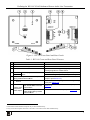
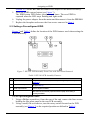
Figure 1 and Table 1 define the front and rear panels and features of the WP-101.
1 Both balanced and unbalanced outputs may be used simultaneously
2 EDID is defined by a standard published by the Video Electronics Standards Association (VESA)
2
KRAMER: SIMPLE CREATIVE TECHNOLOGY
Defining the WP-101 XGA/Unbalanced Stereo Audio Line Transmitter
Figure 1: WP-101 Front Panel and Rear Panels
Table 1: WP-101 Front and Rear Panel Features
#
Feature
Function
1
AUDIO IN 3.5mm Mini Jack
2
PC IN XGA 15-Pin HD (F) Connector
Connect to an XGA video source
3
ON LED
Lights red when receiving power, lights green when
receiving a signal from a video source
4
+12V PIN
GND PIN
5
6
Power Spring-Loaded Terminal
Block
AUDIO OUT 8-pin Audio Line-level Output
Spring-Loaded Terminal Block
8
RGBHV OUT
Component
Video Output 2
Connect to the positive (red/+) of the power adapter
Connect to the negative (black/-) of the power adapter
Connect to balanced and/or unbalanced stereo audio
acceptor1 (see Section 4.3)
Ground connection. Ring-tongue terminal and grounding
screw (see Section 4.2)
Ground
7
Connect to an unbalanced stereo audio source
RGBHV Video Output Cables
with Female BNC Connector
Terminations
Connect to RGBHV component video acceptor (see
Section 4.4)
RGBHV OUT 9-pin RGBHV
Video Output Spring-Loaded
Terminal Block
Connect to RGBHV video acceptor (see Section 4.4)
1 Both balanced and unbalanced outputs may be used simultaneously
2 Only one of these outputs can be active at a time. You cannot connect both simultaneously
3
Defining the WP-101 XGA/Unbalanced Stereo Audio Line Transmitter
4.1 Installing and Connecting the WP-101 XGA Line Transmitter
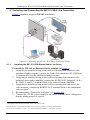
Figure 2 illustrates a typical WP-101 installation.
Figure 2: Connecting the WP-101 XGA/Stereo Audio Line Driver
4.1.1
Installing the WP-101 XGA/Stereo Audio Line Driver
To install the WP-101 as illustrated in the example in Figure 2:
1. Using the pre-installed wiring in the wall box opening that connects to the
unbalanced audio recorder, connect the Audio Out unbalanced (R, GND and
L) terminal block to the unbalanced audio recorder.
2. Using the pre-installed wiring in the wall box opening that connects to the
balanced, stereo audio amplifier, connect the AUDIO OUT balanced 1 (L, R+,
R-, GND, L- and L+) terminal block to the balanced audio amplifier.
3. Using the pre-installed wiring in the wall box opening that connects to the
video acceptor, connect the RGBHV OUT terminal block to the component
video acceptor 2.
4. Recommended—Ground the wall plate (see Section 4.2).
5. Connect the 12V DC power supply to the power terminal block 3 taking care
that the wiring polarity is correct.
1 Both balanced and unbalanced outputs can be used simultaneously
2 Either the BNC or terminal block output can be active, they cannot be connected simultaneously
3 Connect the wire labeled + to the +12V connector and the wire labeled – to the GND connector
4
KRAMER: SIMPLE CREATIVE TECHNOLOGY
Defining the WP-101 XGA/Unbalanced Stereo Audio Line Transmitter
6. Insert the WP-101 into the wall box opening and secure it using the supplied
screws.
4.1.2
Connecting the WP-101 XGA/Stereo Audio Line Driver
To connect the WP-101 as illustrated in the example in Figure 2:
1. Connect the VGA source to the PC IN connector.
2. Connect the unbalanced stereo source to the AUDIO IN connector.
4.2 Grounding the WP-101 XGA/Stereo Audio Line Driver
Grounding the WP-101 is recommended.
The grounding wire is connected to the rear of the chassis of the unit.
Table 2: WP-101 Grounding
Component Descriptions
#
Item
1
M3 x 6 Screw
2
1/8" Toothed lock washers
3
M3 Ring tongue terminal
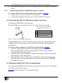
Figure 3: WP-101 Grounding Components
The grounding screw is used to earth the chassis of the unit to the ground of the
building, thus preventing static electricity from interfering with the product’s
performance.
To connect the grounding to the WP-101 as illustrated in Figure 3:
1. Crimp the ring-tongue terminal to the building grounding point wire.
(We recommend that you use a green-yellow 18 AWG wire (0.82mm2)
crimped with a proper hand-tool).
2. Insert the M3x6 screw through the toothed lock washers and the ring-tongue
terminal in the order shown above.
3. Insert the M3x6 screw (with the two toothed lock washers and ring-tongue
terminal in place) into the grounding screw hole on the rear of the WP-101
and tighten the screw.
4.3 Wiring the AUDIO OUT 8-Pin Terminal Block
The 8-pin spring-loaded terminal block is an easy plug-in connector for attaching
the cable to the audio acceptors.
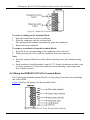
Figure 4 defines the pinouts for the terminal block.
5
Defining the WP-101 XGA/Unbalanced Stereo Audio Line Transmitter
Figure 4: Audio Out Terminal Block Pinouts
To connect cabling to the terminal block:
1. Strip the insulation from each conductor.
2. Press the conductor into the relevant hole.
The spring-loaded contact automatically grips the conductor.
3. Repeat for each conductor.
To remove a conductor from the terminal block:
1. Press the lever corresponding to the conductor to be removed.
2. While pressing the lever, pull the conductor from the connector.
Note:
• Press the spring-loaded lever only when removing wires, not when inserting
them
• Each conductor should protrude 9 mm (0.35") from its insulation so that it can
be easily connected. To prevent conductors from shorting, ensure that each
wire is fully inserted
4.4 Wiring the RGBVHV OUT 9-Pin Terminal Block
The 9-pin spring-loaded terminal block is an easy plug-in connector for attaching
the video cables.
Figure 4 defines the pinouts for the terminal block.
Figure 5: RGBHV OUT Video Terminal Block Pinouts
6
KRAMER: SIMPLE CREATIVE TECHNOLOGY
Assigning an EDID
To insert or remove conductors from the terminal block, follow the instructions in
Section 4.3.
4.5 Wiring the Power Connector
The power supply connections are illustrated in Figure 6.
Figure 6: WP-101 Power Supply Connection
To connect the power supply to the WP-101, as illustrated in Figure 6:
1. Strip about 5mm (0.2”) from the insulation of the power supply wires.
2. Insert the wires fully into the connector block taking care that the polarity is
correct.
3. Using a small, flat screwdriver, tighten the terminal block screws to hold the
wires securely in place.
5
Assigning an EDID
The EDID can either be captured automatically by the WP-101 transmitter (see
Section 5.1), or you can set it manually with one of the preconfigured values (see
Section 5.2).
5.1 Capturing the EDID from a Display Device
To capture the EDID from a display device:
1. Using a Philips screwdriver, remove the four screws holding the faceplate to
the PCB assembly.
2. Using a short cable 1, connect the PC IN 15-pin HD input connector on the
WP-101 to the XGA connector of the display and turn the display on.
3. Ensure that the rotary switch (see Figure 7) is in position 0. If it is not, use a
small screwdriver to turn it to 0.
4. Connect the supplied 12V DC power adapter to the power terminal block (see
1 For example, Kramer model number C-MGM/MGM-1
7
Assigning an EDID
Section 4.5) on the WP-101 and connect the adapter to the mains electricity.
5. Press the EDID capture button (see Figure 7).
The EDID status LED flashes slowly several times. The new EDID is
captured when the LED stops flashing and lights solid.
6. Unplug the power adapter from the mains and disconnect it from the WP-101.
7. Replace the faceplate and secure the four screws removed in Step 1.
5.2 Setting a Preconfigured EDID
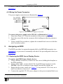
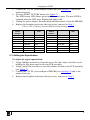
Figure 7 and Table 3 define the location of the PCB features used when setting the
EDID manually.
Figure 7: WP-101 PCB Assembly Front View with Face Plate Removed
Table 3: WP-101 PCB Assembly Features
#
Feature
Function
1
Equalization Trimmer
Using a small, flat screwdriver, turn to adjust the signal equalization (see
Section 5.3)
2
16 Position Rotary Switch
Using a small, flat screwdriver, turn to select the EDID resolution and refresh
rate (see Table 4)
3
EDID Capture Button
Press to capture the EDID
4
EDID Status LED
Flashes green slowly when capturing a valid display EDID; lights solid when
EDID has been successfully captured; flashes rapidly when setting a
preconfigured EDID
To set a preconfigured EDID:
1. Using a Philips screwdriver, from the rear of the unit, remove the four screws
holding the face plate panel to the rear PCB assembly.
2. Using a small, flat screwdriver, turn the rotary switch located on the PCB
assembly (see Figure 7) to the required position as defined in Table 4.
8
KRAMER: SIMPLE CREATIVE TECHNOLOGY
Assigning an EDID
3. Connect the 12V DC power adapter to WP-101 (see Section 4.5) and to the
mains electricity.
4. Press the EDID CAPTURE button (see Figure 7).
The EDID status LED flashes green rapidly several times. The new EDID is
captured when the LED stops flashing and lights solid.
5. Unplug the power adapter from the mains and disconnect it from the WP-101.
6. Replace the faceplate and secure the four screws removed in Step 1.
Table 4: WP-101 Rotary Switch EDID Resolution Settings
Rotary
Switch
Position
Resolution
Refresh
Rate
Rotary
Switch
Position
Resolution
Refresh
Rate
0 (Default)
1024x768
60Hz
8
1440x900
60Hz
1
800x600
60Hz
9
1440x1050
60Hz
2
3
1024x768
1152x864
60Hz
75Hz
A
B
1600x1200
1680x1050
60Hz
60Hz
4
1280x720
60Hz
C
1920x1080
60Hz
5
1280x800
60Hz
D
1920x1200
60Hz
6
1024x1024
60Hz
E
For future use
7
1360x768
60Hz
F
For future use
5.3 Setting the Equalization
To adjust the signal equalization:
1. Using a Philips screwdriver, from the rear of the unit, remove the four screws
holding the face plate panel to the rear PCB assembly.
2. Using a small, flat screwdriver, turn the trimmer located on the PCB assembly
(see Figure 7).
3. Connect the 12V DC power adapter to WP-101 (see Section 4.5) and to the
mains electricity.
4. Replace the faceplate and secure the four screws removed in Step 1.
9
Technical Specifications
6
Technical Specifications
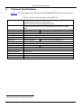
Table 5 lists the technical specifications of the WP-101 XGA/Stereo Audio Line
Driver.
Table 5: Technical Specifications 1 of the WP-101
INPUTS:
OUTPUTS:
MAX. OUTOUT LEVEL:
BANDWIDTH (-3dB):
DIFF. GAIN:
DIFF. PHASE:
1 UXGA on a 15-pin HD (F) connector
1 Unbalanced stereo audio on a 3.5mm mini jack
1 Power 12V DC on 2-pin spring-loaded terminal block
1 Audio balanced and 1 unbalanced on an 8-pin spring-loaded terminal block
1 RGBHV component video on a 9-pin spring-loaded terminal block or on 5 BNC
cables
Video: 1.7Vpp
Audio: 8.5Vpp unbalanced, 16.6Vpp balanced
Video: 380MHz
Audio: >20kHz
0.08%
0.05Deg
K-FACTOR:
0.2%
S/N RATIO:
Video: 68dB @5MHz
Audio: 87dB unbalanced, 85dB balanced
CROSSTALK (all hostile): Audio: -51dB (from video)
CONTROLS:
0 to 10dB equalization @50MHz
COUPLING:
Video: DC
AUDIO THD + NOISE:
0.01%
Audio: Input AC, Output DC
AUDIO 2nd HARMONIC:
Unbalanced 0.003%, balanced 0.001%
POWER SOURCE:
12V DC 80mA
DIMENSIONS:
2 Gang US 114.3mm x 114.3mm (4.5" x 4.5") W, D
WEIGHT:
ACCESSORIES:
0.14kg. (0.31lbs.) approx.
Power adapter
1 Specifications are subject to change without notice
10
KRAMER: SIMPLE CREATIVE TECHNOLOGY
11
For the latest information on our products and a list of Kramer
distributors, visit our Web site www.kramerelectronics.com
where updates to this user manual may be found.
We welcome your questions, comments and feedback.
Safety Warning:
Disconnect the unit from the power supply before
opening/servicing.
Caution
Kramer Electronics, Ltd.
Web site: www.kramerelectronics.com
E-mail: [email protected]
P/N: 2900-000655 REV 2