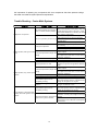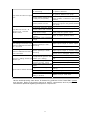
1
Installation and Troubleshooting Manual
Lincoln Automatic Lubrication Systems
One Lincoln Way, St. Louis, MO 63120 (314) 679-4200, Fax (314) 679-4359
Table of Contents
MACHINE SURVEY ..............................................................................................................................3
COMPONENT LOCATION ........................................................................................................................................ 3
PUMPS ................................................................................................................................................................. 3
LUBRICANT METERING DEVICES ............................................................................................................................. 3
SUPPLY AND F EED LINES ...................................................................................................................................... 3
COMBINING OUTPUT OF MULTIPLE METERING DEVICES TO ONE BEARING.......................4
CENTRO-MATIC INJECTORS .................................................................................................................................. 4
Side Adjustment Injectors: ........................................................................................................................... 4
SL-32, SL-33, SL-42 & SL-43...................................................................................................................... 4
Top Adjusting Injector types: ....................................................................................................................... 4
SL-11 Injectors ............................................................................................................................................. 4
Modular Lube UV Divider Valves ................................................................................................................ 5
Quicklub Divider Valves ............................................................................................................................... 5
SUPPLY LINE SELECTION .................................................................................................................6
SUPPLY LINE MATERIALS ...................................................................................................................................... 6
TUBING ................................................................................................................................................................ 6
PIPE .................................................................................................................................................................... 7
HOSE ................................................................................................................................................................... 7
SUPPLY LINE LAYOUT .......................................................................................................................7
GUIDELINES FOR LOW PRESSURE OIL SYSTEMS: .................................................................................................. 7
GUIDELINES FOR HIGH PRESSURE GREASE S YSTEMS: .......................................................................................... 8
SYSTEM START-UP AND TROUBLE SHOOTING ...........................................................................8
INITIAL START-UP – CENTRO-MATIC S YSTEMS ...................................................................................................... 8
Fine Tune Outputs ....................................................................................................................................... 8
INITIAL START-UP – MODULAR LUBE AND QUICKLUB PROGRESSIVE SYSTEMS ........................................................ 9
TROUBLE SHOOTING – CENTRO-MATIC SYSTEMS ..................................................................10
TROUBLE SHOOTING – QUICKLUB PROGRESSIVE SYSTEMS ...............................................12
TROUBLE SHOOTING - MODULAR LUBE SYSTEMS..................................................................13
DESCRIPTION ................................................................................................................................................ 13
DIVIDER V ALVES ................................................................................................................................................ 13
PERFORMANCE INDICATORS .................................................................................................................... 13
Reset Type Performance Indicators.......................................................................................................... 13
Pin Type Indicators .................................................................................................................................... 14
Atmospheric Indicators .............................................................................................................................. 14
LOCATING BLOCKAGE IN A MODULAR LUBE SYSTEM ...........................................................14
PROCEDURE ...................................................................................................................................................... 14
Master Divider Valve Equipped With Performance Indicators:................................................................ 14
Master Divider Valve Without Performance Indicators: ........................................................................... 15
OTHER BLOCKAGE ............................................................................................................................................. 16
Contamination ............................................................................................................................................ 16
LUBRICANT SEPARATION .................................................................................................................................... 16
CENTRO-MATIC SYSTEM SCHEMATIC .........................................................................................17
MODULAR LUBE SYSTEM SCHEMATIC........................................................................................18
QUICKLUB SYSTEM SCHEMATIC ..................................................................................................19
2
Machine Survey
It is recommended that in the process of developing the lube system, a survey of the machine is
made, and a schedule of lubrication points is created. This schedule should include the location
of the bearing or lube point, the bearing size, 8-Hour lube requirement, and the measuring
devices to use at each point. It may also be desirable to add an area for any remarks for each
lube point and note any special considerations, which must be made for that particular point. This
schedule will help in further development of the automatic lubrication system.
During the machine survey, attention should be given to potential mounting locations for the
specific automatic lubrication system components. It is advisable to discuss these locations with
a representative of the customer who is knowledgeable about the operation and function of the
piece of equipment being surveyed. A location the system designer feels is a logical place to
mount a component may turn out to be inappropriate because of certain aspects of the machine’s
operation or maintenance.
Component Location
Components of an automatic lubrication system should be mounted in areas that will allow the
system to operate efficiently, as well as allowing access for routine maintenance, inspection,
troubleshooting and repair.
Pumps
Factors to consider when locating the pump are:
• Accessibility to the power source for the pump. Pumps can be manually activated, or
powered by compressed air, hydraulic fluid, or electrical current.
• Protected from possible damage that could be caused by operation of the equipment, or
extraneous factors resulting from the function of the machine.
• Refilling or replacement of the lubricant reservoir.
• Testing and troubleshooting system operation.
• Routine maintenance
• Repair
Lubricant metering devices
Factors to consider when locating lubricant measuring devices are:
• Grouped in such a way that the largest number of lubrication points can be serviced from
a single location with the minimum length of feed line possible.
• Located to allow maintenance personnel safe, easy observation of cycle indication
devices.
• Located in an area that affords adequate protection from damage that could be caused
as a result of normal operation of the machinery, or extraneous factors resulting from the
function of the machine.
• Located such that maintenance personnel can safely and easily perform maintenance
and repair.
Supply and Feed Lines
Factors to consider when routing lubricant supply and feed lines are:
• Keep lines as short as possible.
Route lines in such a way that they can be easily anchored or secured to the equipment.
•
Ensure lines are protected from damage that could occur as a result of normal operation
of the machine, or extraneous factors resulting from the function of the machine.
3
•
•
When lubricant lines are routed in an area where they could be damaged, adequate
guarding must be installed. Common materials such as angle iron, channel iron, and
heavy wall pipe can all be used to fabricate guards.
Be sure to allow adequate slack in lines to facilitate for movement of parts of the
machine.
Combining Output of Multiple Metering Devices to One Bearing
Centro-Matic Injectors
Many times it may be more economical to combine the output of two or more injectors to feed one
bearing rather than using a larger injector. The examples below indicate how this procedure is
done with each of the Lincoln Centro-Matic injectors.
Side Adjustment Injectors:
SL-32, SL-33, SL-42 & SL-43
A 1/8” tube tee, such as 82665 can be used to
combine the lubricant output from two injectors
into a single feed line to service one bearing
whose lubricant requirement exceeds the capacity
of a single injector. This arrangement is rarely
used as a larger output injector may be used.
Top Adjusting Injector types:
SL-1, SL-41, SL-44, and SL-V
These injectors are designed so that the lubricant output of
two or more injectors can be combined without the use of
tees. The injector body has two outlet ports, one above
the other. Connector tube part number 81646 is used to
couple the injectors together. Lubricant from injector #1 is
directed through the connector tube into the discharge
chamber of injector #2. Lubricant does not go through the
mechanism of injector #2, but simply combines with the
lubricant delivery of injector #2 to yield more output from
the outlet of injector #2. This does not interfere with the
operation of either injector.
SL-11 Injectors
A method of combining outputs similar to that shown above is
used except that the connector tube is fabricated to fit at the
time of installation as shown to the right.
Important Note:
4
Use only one feed line and injector per bearing as shown on the right. Do not combine two feed
lines together for two lube points, as shown on the left. In other words, it is ok to feed one
bearing with 2 or more injectors. It is not acceptable practice to feed two or more bearings with
one injector. If two bearings are supplied by one feed line, as shown in the example on the right,
one or the other bearing will received more lubricant than the other bearing. The flow will flow to
the bearing of least resistance. One bearing will be starved while the other will be over
lubricated.
Modular Lube UV Divider Valves
The output volumes of Modular Lube divider valve segments can be combined in order to
increase the amount of lubricant delivered to a
single point. This is usually only necessary when
the lubricant requirements of a given lubrication
point exceeds the output volume of the largest UV
valve section.
In order to combine the lubricant output of two
adjacent valve sections, a cross-port plate is
utilized. Cross-port plates are available in three
different configurations – cross-port left, cross-port
right, and cross port both.
A cross-port left plate (87945) will divert the
lubricant volume normally dispensed from the left
hand outlet of a valve section, and re-direct it to the left hand lubricant outlet of the divider
valve directly below it.
A cross-port right (87944) plate will function in the same fashion as the cross port left, but
divert the lubricant volume to the right hand side lubricant outlet.
A cross-port both plate (87946) will direct the lubric ant volume from a “T” or twin section to
the valve section directly below it.
Quicklub Divider Valves
5
Outputs from adjacent outlets may be combined by installing a special closure plug (303-174993) in one or more outlets. Lubricant from a plugged outlet is redirected to the next adjacent outlet
in descending numerical order. Outlets 1 and 2 must not be plugged since they have no
cross-port passage to the next adjacent outlet.
Long Plain and Flat Bearings, Large Diameter Bearings
Special consideration should be given to bearings that are extremely long or large in diameter.
Combining injector outputs to feed one lube point was discussed in preceding paragraphs. In
some installations where bearings are very large or are very long, better practice may be to
lubricate the bearing with two or more inlets along the bearing length or around the diameter of a
very large bearing. This practice will result in better distribution of the lubricant and may allow
lubricant to reach areas of the bearing that would not receive lubricant with only one inlet. The
total bearing capacity is calculated in the normal manner, but the number of injectors used to
service the bearing divides the 8-Hour requirement of the bearing up.
Supply Line Selection
After the lubricant has been determined and the injectors have been selected, the size is
determined for the main and branch supply lines. When performing the survey of the machine,
note the locations of all injector banks, where the main supply line and branch lines are to run.
The lengths of these supply lines will have to be determined and recorded on the schedule.
Supply Line Materials
The preferred material to use for supply lines in a lube system is steel tubing or pipe. Hose may
be used but special cautions must be taken when using hose. Hose is not the preferred material
to use.
Safety
The pumps used in Centro-Matic Centralized Lubrication Systems are capable of
generating very high pressures. Serious injury is possible if a system is improperly
designed and installed. It is the responsibility of the system designer to insure that the
pressure ratings of all piping, tubing, hose, and fittings used in the installation of a
Centro-Matic system will meet or exceed the pressures that can be generated by the
pumps used in the system. The maximum operating pressure of a High Pressure
Grease system is 3500 PSI with a typical working pressure of 2500 PSI. Low Pressure
Oil Systems ha ve a maximum operating pressure of 1000 PSI with a typical operating
pressure of 850 PSI. The maximum operating pressures should not be exceeded.
Tubing
Soft annealed DOM; welded, or seamless hydraulic tubing is recommended for use in all lube
systems. The advantage over pipe is that it is devoid of scale and has a smoother bore, which
allows for better flow and has fewer chances of contamination. Tubing may be less costly to
install because it is easily bent; reducing the number of fittings used, and eliminates thread
6
cutting. See the supply line charts for each system type for recommended tube size and wall
thickness to use.
Copper tubing should never be used in lubrication systems, as it is not rated for the
pressure which can be developed in an automatic lubrication system.
Do not confuse Lincoln’s copper-coated steel tubing (62175; 62176) with copper tubing.
The copper coating on the steel tubing is to provide corrosion resistance to the steel
tubing.
Pipe
In some areas it may be more desirable or economical to use pipe. The pipe should be
thoroughly cleaned of scale. Scale can cause injectors to stick and ruin bearings. To assure
absence of scale the pipe should be flushed or pickled, oiled and capped. Pipe meeting ASTM A53 Grade B, ASTM A-106 Grade B or an equivalent grade of seamless steel pipe should be used.
The pipe schedules as specified in the supply line charts for each system type should be used.
Fittings should meet or exceed the pressure requirements of the system they are installed on.
Forged steel fittings are recommended. Cast malleable iron “water or gas” fittings should not be
used.
Hose
Hose may be used in supply lines. In many cases hose must be used as part of the supply line
where it must cross into a moving area of the machine. The hose must be rated to meet or
exceed maximum system pressures that will be used with the system. It must be noted, when
calculating total system requirements, hose expansion can be 40 times or more greater than
pipe or tubing when it is pressurized, depending on the hose. In applications where a single shot
pump is used, or where pumping time is critical the hose expansion should be confirmed before
designing the system.
Supply Line Layout
A lube system should always be laid out to make the most economical use of the supply line.
Excessively long lines increase the cost of the installation, require a larger diameter pipe or tube
for satisfactory venting, and demand more lubricant per lube cycle to allow for expansion. The
layout should be planned with these points in mind and the shortest runs possible from the pump
Experience with many installations has resulted in several useful and practical guidelines, which
cannot be included in a chart, but should be understood and applied when designing and
installing a system.
Guidelines for Low Pressure Oil Systems:
1.
2.
3.
4.
5.
Use the same size pipe or tubing on all parts of the main supply line, including riser,
ceiling run, branch lines, and drop lines.
Where the main supply line has various branch lines, the branch lines can be reduced by
one pipe or tubing size, provided the supply line size is not the maximum length specified
on the Low Pressure Oil Supply Line Chart.
The tube or pipe between injectors on the specific machine should be determined by the
injector inlet thread size. Use corresponding size pipe or tube fitting thread size.
All supply and feed lines are to be supported at regular intervals in accordance with
accepted plumbing practice.
In general, the best system design for a machine is to combine the injectors to the best
advantage to form injector groups, and then run the supply line from the branch line to
each of the injector groups.
7
Guidelines for High Pressure Grease Systems:
1.
2.
3.
4.
5.
6.
Using a manual grease gun, confirm each lubrication point, which will be
connected to the lubrication system, will ac cept lubricant.
Use the same size pipe or tubing on all parts of the main supply line, including riser,
ceiling run, branch lines, and drop lines.
Where the main supply line has various branch lines; the branch lines can be reduced in
size by the use of the Pipe or Tube Equivalency Charts in the Appendix.
The tube or pipe between injectors on the specific machine should be determined by the
injector inlet thread size. Use corresponding size pipe or tube fitting thread size. These
lengths of pipe or tubing should be added to the total run using the Pipe or Tube
Equivalency Charts in the Appendix.
All supply and feed lines are to be supported at regular intervals in accordance with
accepted plumbing practice.
In general, the best system design for a machine is to combine the injectors to the best
advantage to form injector groups, and then run the supply line from the branch line to
each of the injector groups.
System Start-up and Trouble Shooting
Initial Start-up – Centro-Matic Systems
Set output. When installing the Centro-Matic system, all injectors should be set for full (max.)
output. The injectors will be adjusted to the correct output later.
• Flush the system. It is important to keep the Centro-Matic system clean and free of any dirt,
scale, sand, and other debris. If the tubing, pipe, and hoses used in the system installation
have been cleaned and capped prior to installation, and you feel certain that the components
have been kept clean this step can be avoided. On large systems, flush the system to
remove pipe scale, hose debris, and other debris left by the installation process. A mixture of
light oil (about 25%) and mineral spirits (75%) is a good flushing media.
• Fill the system and purge. Fill the system with the correct lubricant and purge out any flush
that may have been used, and air. Start purging at the pump first, then purge air at the
injector farthest from the pump, working your way back to the pump.
• Start lube system operation. Make sure that the injectors that are the greatest distance from
the pump are cycling. If not, increase system pressure until they do, or determine cause of
problem. A pressure gauge installed into the last injector manifold can help with this task and
other trouble shooting procedures later. Insure that all injectors are cycling. Visually check
all indicator pins for operation.
• Lock regulators or pressure reducing valves. Once satisfied that the system is operating
normally, and the pressure is normal. On air systems, lock the air regulators with the
supplied lock nuts or make sure regulator knob is positioned so it is not easily changed. The
lock nut on pressure reducing valves and flow control valves on hydraulic pumps should be
tightened.
• Allow the system to run at full output. At least until satisfied that the system is operating, as it
should. Some machine builders and customers may require operation at full output for a
prescribed break-in period. After this period, adjust each injector down to the required output
for the lube point it serves.
Fine Tune Outputs
•
After the system has been in operation for a while, it may be necessary to make slight
adjustments to the outputs. Some bearings may be receiving too much lubricant and some may
need more.
8
Individual points can be adjusted at the injector. By adjusting the output at the injector the
lubricant output can be adjusted to suite one individual point. If all or the majority of all the
system needs more or less lubricant, the cycle rate can be increased or decreased as required.
In some situations it may be necessary to add injectors to increase the output to one or two
specific lube points. See Section 2 of this manual for combining injector outputs.
Inform The Customer
Instruct the customer in system operation and service. Explain to the customer, system
operation, simple trouble shooting procedures, and how to fine-tune the system controller and
injector outputs if more or less lubricant is required. Reinforce the necessity for keeping the
lubricant clean. Show the customer how to change or refill the lubricant reservoir. Inform the
customer of the system operating pressure and the importance of replacing any components with
new components that have pressure ratings that meet or exceed the system pressure
requirements.
Initial Start-up – Modular Lube and Quicklub Progressive Systems
•
•
•
•
•
Flush the system. It is important to keep the progressive system clean and free of any dirt,
scale, sand, and other debris. If the tubing, pipe, and hoses used in the system installation
have been cleaned and capped prior to installation, and you feel certain that the components
have been kept clean this step can be avoided. On large systems flush the system to
remove pipe scale, hose debris, and other debris left by the installation process. A mixture of
light oil (about 25%) and mineral spirits (75%) is a good flushing media.
Prime the system and purge. Fill all supply lines, feed lines, and measuring valves in the
system with the correct lubricant and purge out any flush that may have been used. Continue
priming of all lines until lubricant flowing from the open line is free of air. Start purging at the
pump first, then purge air at the divider valve farthest from the pump, working your way back
to the pump.
Start lube system operation. Make sure that the measuring valves that are the greatest
distance from the pump are cycling. If not, increase system pressure or pump output until
they do, or determine cause of problem. Insure that all divider valves are cycling. Visually
check all cycle indicator pins for operation.
Lock regulators or pressure reducing valves. Once satisfied that the system is operating
normally, and the pressure is normal. On air systems, lock the air regulators with the
supplied lock nuts or make sure regulator knob is positioned so it is not easily changed. The
lock nut on pressure reducing valves and flow control valves on hydraulic pumps should be
tightened.
Allow the system to run at full output. At least until satisfied that the system is operating, as it
should. Some machine builders and customers may require operation at full output for a
prescribed break-in period.
Inform The Customer
Instruct the customer in system operation and service. Explain to the customer, system
operation, simple trouble shooting procedures, and how to set the system controller, and air
regulator. Reinforce the necessity for keeping the lubricant clean. Show the customer how to
change or refill the lubricant reservoir. Inform the customer of the system operating pressure and
9
the importance of replacing any components with new components that have pressure ratings
that meet or exceed the system pressure requirements.
Trouble Shooting – Centro-Matic Systems
Symptom
Possible Cause
Corrective Action
Turn on power to controller, timer or motor. Most
timers and controllers have power lamp that
No electrical power to controller,
should light when power is present. Check
timer, or motor (electric pumps)
fuses/circuit breakers on circuit(s) for all CentroMatic system components.
Pump does not operate
Make sure air or hydraulic fluid is applied to
pump and pressure to pump is adequate.
No air or hydraulic pressure to pump
Worn or damaged solenoid valve. Replace
solenoid valve
Open solenoid valve coil. Replace coil.
Make sure air or hydraulic pressure to pump is
set correctly.
Low system pressure
Leak in supply line. Repair leak.
Worn or Damaged injector. Repair or replace.
Pump too small for system. Install pump with
Pump operates, but injectors do not
greater output.
cycle
Low system pressure (Single stroke
Hose expansion greater than planned. Remove
pump)
and replace with steel tube or hose with less
volumetric expansion.
Lubricant reservoir is empty
Fill lubricant reservoir
Air in supply line or pump
Purge air from pump and supply line
Increase system pressure as required. Check
System pressure too low
pressure at injectors the greatest distance from
pump.
Pump too small for system. Install pump with
greater output.
Low system pressure (Single stroke
Hose expansion greater than planned. Remove
pump)
and replace with steel tube or hose with less
Pump operates, only some injectors
volumetric expansion.
operate.
Air in supply line or pump
Purge air from pump and supply line
Lubricant reservoir is empty
Fill lubricant reservoir
Check system pressures during pause time and
Centro-Matic system is not
insure that system vents to a pressure low
completely venting.
enough for all injectors to recycle.
Wrong injector types installed in lube
Insure that all injectors are the correct injector for
system
the type of lubricant in use.
Check system pressures during pause time and
Centro-Matic system is not
insure that system vents to a pressure low
completely venting.
enough for all injectors to recycle.
Allow more pause time for venting
In cold weather, pump operates
Change lubricant to a winter grade lubricant with
normally but some injectors fail to
ventmeter viscosity low enough for the system
operate
Lubricant Ventmeter Viscosity tooinstalled
high for the system installed
Increase the size of the supply line to meet the
requirements of the lubricant and temperatures
encountered.
10
Pressure switch incorrectly set or
Set pressure switch to correct system pressure
not functioning
or replace if defective.
Move pressure switch closer to injector that is
Pressure switch too close to pump
the greatest distance from pump.
Pump turns off before all injectors
Use Lincoln pressure switch or insure that
cycle
Pressure switch reacting to surges
proper snubber is installed in other pressure
in supply line (Oil systems)
switches
Increase system pressure as required. Check
System pressure too low
pressure at injectors the greatest distance
from pump.
Pressure switch incorrectly set. Adjust pressure switch to correct pressure.
No electrical connection between
Repair electrical connection to pressure switch
Pump does not turn off. All
pressure switch and controller.
injectors cycle. Controller
Pump output too small for system
Install pump with greater output.
indicates alarm.
(Single Stroke Pumps)
Pressure switch damaged, worn, or
Repair or replace pressure switch
clogged
Lube system is not cycled often
All bearings are under lubricated
Increase lube frequency
enough
All bearings are over lubricated Lube system is cycling too oftenDecrease lube frequency
Most bearings receive the correct
Specific injector(s) is over
amount of lubricant but some are
lubricating
over lubricated.
Adjust injector output to reduce output.
Most bearings receive the correct
Specific injector(s) is under
amount of lubricant but some are
lubricating
under lubricated.
Adjust injector output to increase output.
Injector worn or damaged. Repair or replace.
Injector worn or damaged. Repair or replace.
Replace seal on indicator pin
Top Adjustment Injectors: Seal on
Worn indicator pin. Replace indicator pin and
Lubricant is leaking around injector
indicator pin is leaking
seal.
indicator pin
Side Adjustment Injectors: Seal inReplace seal in measuring chamber
measuring chamber leaking.
Injector body worn. Replace injector.
Injector output adjusted for minimal
Adjust injector output
output
Remove blockage from feedline or check
Plugged feedline or tight bearing.
bearing.
Injector fails to deliver lubricant
Injector spring(s) worn or broken
Replace spring(s)
Injector piston(s) sticking or worn
Replace injector
Injector check valve (side adjust)
Replace O-ring or clean check
leaking or blocked
Use the trouble-shooting chart above, for determining problems in the Centro-Matic system
and injectors. Refer to the owner’s manual of specific components, such as pumps and
controllers for problems regarding those specific components.
11
Trouble Shooting – Quicklub Progressive Systems
Fault: Blockage in the downstream progressive system
Cause:
•
•
Correction:
Bearing, lines, or metering valves clogged.
In the case of SSV 6 through SSV 12 metering valves, outlet
ports 1 and/or 2 are closed.
The fault can be identified by :
a) Grease leaking from the pressure relief valve;
b) The fact that the indicator pin on the primary valve does not
move in and out when the pump runs.
•
Determine which is the cause of the blockage and rectify it in
accordance with the following procedure:
•
Allow pump to run by triggering a manual lube cycle.
•
Loosen all main line connections one after another from the
primary metering valve leading to the secondary metering
devices. If grease emerges under pressure from one of the
primary valve outlets, the blockage is in the lubrication circuit
of the secondary valve connected to that port.
If a downstream blockage is determined;
•
•
•
•
•
Let the pump run.
Disconnect feed lines from the secondary metering valve
which was determined to have the blockage. If grease
emerges under pressure from one of the outlets, the
blockage will be found in the line or bearing connected to
that outlet.
Pump the blocked line or bearing with a manual pump to
clear the blockage.
Insure outlet ports 1 and/or 2 do not have closure plugs
installed.
Replace the metering device or clean it in accordance with the
following procedure:
Metering device blocked
•
•
•
•
•
•
•
•
•
•
Fault: Differing amounts of lubricant at the lubrication points
Cause:
•
Lubricant metering not correct
•
Remove all tube fittings
Unscrew the piston closure plugs (M11 x 1).
If possible, try to eject the piston using a smooth drift (Ø
smaller than 6mm; 0.24 in.).
IMPORTANT: The pistons are precision-fitted into the valve
body. Mark the pistons with regard to their installation
position and direction after they have been removed. They
must not be exchanged.
Thoroughly clean the metering device bodies in clean
solvent, blow them trough with compressed air.
Clean the slant ducts (Ø 1.5 mm; 0.59 in.) at the thread ends
of the piston holes using a pin.
Clean the metering devices again, and blow them through.
Reassemble the metering devices.
Replace the copper washers, if installed.
Before the tube fittings are reassembled, the metering
devices should be pumped with oil several cycles by means
of a manual pump. Check that the pressure in the metering
device does not exceed 25 bar (362.8 psi).
If the pressure is higher, replace the metering device.
Correction:
•
Check the lubricant metering according to lubrication chart.
•
Respective outlet adapter has been assembled without
clamping ring
•
•
Setting of the pause time or operating time incorrect
Check the time setting. Refer to corresponding setting in the
respective operating instructions.
Fault: Over or Under lubrication of the lubrication points
Cause:
•
Setting of pause time or operating time incorrect
12
Remove the outlet adapter and install a clamping ring.
Correction:
•
Check the time setting of the control unit.
Trouble Shooting - Modular Lube Systems
DESCRIPTION
In a Lincoln Modular Lube lubrication system, lubricant from the pump flows through the metering
devices and to the lubrication points serviced by the system. If any component of this system
does not freely accept and discharge its portion of the lubricant, a blockage has occurred.
This blockage will result in higher than normal pressure to be developed by the lubricant pump.
Depending on the application or system design, this blockage can cause a complete loss of
lubricant flow through the entire system, and no lube point will receive lubricant.
A blockage is indicated by higher than normal system pressure developed by the pump as it
attempts to deliver lubricant. The higher pressure resulting from a blockage can be indicated
through the use of performance indicators, or other devices such as pressure switches,
incorporated into the system design.
Divider Valves
A Modular Lube divider valve is a proportioning device consisting of an inlet and end section, and
a minimum of three working divider valve sections. A master divider valve is the first divider valve
downstream from the lubricant pump, and usually proportions lubricant to a series of secondary
divider valves.
Divider valves contain a piston specially fitted to that section, built in outlet check valves, and
various passageways that direct and meter the flow of lubricant.
Divider valves are manufactured with either one (single) or two (twin) lube outlets. Stampings on
the face of each section indicate the series of divider valve (UV, MC, MM), the lubricant volume
3
discharged per piston stroke expressed in thousandths of cubic inches (35 = .035 in ), and the
number of lube outlets required (S = single, one outlet only; T = twin, two lube outlets required).
Caution: Never block a lubricant outlet port that is designed to discharge lubricant.
PERFORMANCE INDICATORS
Lincoln performance indicators are pressure-sensitive devices that pinpoint excessive pressure in
series progressive lubrication systems. These devices, which are installed in the alternate outlet
ports of divider valves, signal a fault either by causing an indicator pin to protrude or by releasing
lubricant to the atmosphere.
It is recommended that some type of performance indicator be used to monitor every working
outlet of a Modular Lube System.
Reset Type Performance Indicators
Reset indicators stop lube system operation when a fault occurs. These devices can be used in
either master or secondary divider valves. When a lube line becomes blocked, the resulting high
pressure extends the indicator pin.
The high pressure prevents the affected divider valve piston from completing its cycle, causing
pressure to backup through the divider valve. The indicator pin remains extended until it is reset
manually. This helps locate the lube line that is blocked.
13
Pin Type Indicators
High pressure from lube line blockage causes a pressure sensitive disc to rupture. The lubricant
then forces an indicator pin to protrude, indicating the location of the blockage. The high
pressure backs up through the system. When the fault is corrected, the disc must be replaced
and the pin reset manually.
Atmospheric Indicators
These indicators give visual indication of excessive system pressure. Rupture discs are available
in a range of burst pressures to suit various operating pressure requirements. The pressure disc
ruptures at a predetermined pressure setting, releasing lubricant to the atmosphere and relieving
the high pressure.
Atmospheric type rupture indicators allow lubricant to continue to be delivered to all lube
points not affected by the blockage.
LOCATING BLOCKAGE IN A MODULAR LUBE SYSTEM
If a blockage occurs in a Lincoln Modular Lube system, it is caused by one of the following
reasons:
•
•
•
•
Crushed or crimped lubricant supply line or feed line.
Blocked bearing in the system.
Improperly drilled fitting in the system.
Blocked divider valve in the system.
All servicing and disassembling should be carried out under the cleanest conditions possible. A
blockage in a Lincoln Modular Lube system will be indicated by a pressure gauge, pressure
switch, controller, or by the atmospheric relief indicator on the pump exhausting lubricant.
Before proceeding as outlined, make a visual inspection of the system and check for crushed or
crimped lines, or improper divider valve installation. Verify that each divider valve outlet required
to discharge lubricant can do so, and that no pipe plugs have been installed in an outlet designed
to dispense lubricant to a bearing or to another divider valve.
Procedure
Step 1
Use a manual pump with a gauge. Fill the pump with clean, filtered lubricant common to the
system. Connect the manual pump to the inlet of the master divider valve and slowly operate
pump. If system will not cycle freely below 1,500 PSI, see Step 2.
Step 2
Master Divider Valve Equipped With Performance Indicators:
With manual pump connected to the master divider valve as outlined in Step 1, raise pressure to
2,000 PSI, the indicators in the alternate outlet ports will signal the location of the blockage. An
indicator in the up position indicates pressure is in that outgoing line and the blockage is in the
area being served from this outlet. If no indicator pins are protruding, the blockage is in the
master divider valve.
14
Master Divider Valve Without Performance Indicators:
With pressure on the master divider valve as outlined in step 2, remove the alternate outlet plugs
one at a time and attempt to operate the manual pump after each plug is removed. Do not
exceed 2,000 PSI. If pressure drops and the master cycles freely after an alternate outlet plug is
removed, then blockage is downstream in the area that is being served from that lubricant outlet.
See Step 3.
If all indicator port plugs are removed and master will not cycle, blockage is in this divider valve.
Caution: When the indicator port plug of a blocked area is removed, a small shot of
trapped lubricant will usually surge out of this outlet as the inlet pressure on the divider
valve drops.
If testing in Step 2 indicates a blockage in the master divider valve, this divider valve must be
disassembled and cleaned.
Step No. 3
Testing accomplished in Step 2 has indicated the blockage is downstream of the master divider
valve. Install the manual pump in the alternate outlet port of the master divider valve that is
common to this blocked area. Proceed to downstream secondary divider valve and remove all
alternate outlet port plugs. Slowly operate manual pump. If lubricant can be discharged freely
through each of the alternate outlet ports of this divider valve, the blockage is not in the supply
line or the divider valve, see Step 4. If lubricant is not freely discharged through the open
alternate outlet ports of the secondary divider valve the blockage is in this divider valve or its
supply line.
Disconnect supply line at the secondary divider valve inlet fitting and slowly operate manual pump
to verify location. If blockage is in divider valve see Step 5.
Step No. 4
Install manual pump into each alternate outlet port of secondary divider valve in turn, and slowly
operate pump. If high pressure exists, the blockage has been located. Look for a crushed or
crimped line, tight bearing, improperly drilled fittings and/or lube inlet port. Correct as
necessary.
Step No. 5
When testing indicates a blockage has occurred in any divider valve, that divider valve must be
disassembled and cleaned.
Note: Dirt and foreign material are the worst enemies of any lubricating equipment. All
servicing and disassembling should be performed under the cleanest possible conditions.
Before disassembling any divider valve, make a sketch and note as to the arrangement of
the divider valve sections. For example: INLET-5T-20S-10T-30S-END.
Remove end plugs only and try to move each piston back and forth without removing the piston
from the valve section.
Caution: Do not insert hard metal objects into piston bore (i.e. punches, screwdrivers, etc.)
Use a brass rod and hand pressure only.
If all pistons are movable and there is no indication of a more serious problem, replace end plugs
using new gaskets. Retest this divider valve using the manual pump. If a piston is jammed, or a
hard wax-like substance or dirt is noted at the end of the piston chamber, proceed with
15
disassembly. With the individual sections on the bench, remove the end plug from both ends of
the section.
Taking one section at a time remove the piston, if it appears to be jammed, try removing it from
the other direction. With badly jammed pistons it may be necessary to use a brass rod and lightly
tap piston out.
Clean sections and pistons in a suitable clean solvent until all lubricant has been removed. Use
compressed air to dry and blow out all ports thoroughly. Ensure all passages are clean and open
by inserting a small wire probe into each passageway. Inspect the cylinder bore and piston
carefully for scratches, score marks or other damage.
Note: If either piston or cylinder bore is damaged, a new section must be installed. All pistons
are selectively fitted to the bore for proper clearance. Care must be taken to install piston only
into the divider valve section from which it was removed.
If divider valve section and piston both appear in good condition, reassemble section making
certain that piston moves smoothly but snugly in cylinder bore. Repeat cleaning and inspection of
each section. After all sections have been cleaned, blown out, inspected and found to be in good
condition, reassemble divider valve as indicated by the notes and sketches.
Caution: Use all new gaskets, and tighten divider valve sections to correct torque values.
Test operation of divider valve using manual pump.
Other Blockage
Contamination
If dirt, foreign material or any other form of contamination is found in a divider valve, cleaning that
divider valve will only temporarily solve contamination blockage problems. If contamination is
an issue, the source of the contamination must be determined and eliminated for
satisfactory lubrication system operation.
Potential sources of contamination can be the reservoir filling method, dirty or missing lubricant
filters, or the lubricant itself. The method of filling the reservoir should be reviewed to eliminate
any chance of foreign material being introduced during the filling operation. Lubricant filters
should be inspected to determine if the filter elements are clogged or missing, and corrective
action taken. Some grease lubricants contain high concentrations of lubricating solids, and are
not suitable for use in an automatic lubrication system.
Lubricant Separation
Some lubricating greases will separate under the operating pressures in an automatic lubrication
system. When separation occurs, a hard wax or soap-like material is found in the divider valve
sections. Separation is a result of oil in the lubricant being squeezed from the thickener of the
grease. The deposits in the divider valve are the thickening component of the lubricant. If
separation is occurring, cleaning the divider valve will usually only temporarily solve the problem,
and an alternative lubricant should be recommended..
Consult your lubricant supplier for recommendations on alternate lubricants and your local Lincoln
Distributor to verify compatibility with progressive lubricating systems.
16
Centro-Matic System Schematic
Centro-Matic System Notes
•
•
•
•
•
•
•
Centro-Matic systems operate with lubricant pressure provided by the pump.
The system must “vent” or reduce the pressure in the lubricant supply line to a pressure
low enough that the injectors will reload with lubricant for the next lubrication cycle. This
is the purpose of the vent valve.
If one injector in the system fails, all other injectors will continue to deliver lubricant
normally.
The output of each injector is adjustable within the output range of the injector.
You can mix injectors of different sizes in the same Centro-Matic system.
Do not mix oil and grease injectors.
Pressure switches should be located at a point farthest from the pump to insure sufficient
lubricant pressure to cycle the injectors is developed throughout the entire system.
17
Modular Lube System Schematic
Modular Lube System Notes
•
•
•
•
•
•
•
•
•
•
•
•
Modular lube divider valves must have a minimum of three working sections.
Modular lube progressive systems operate on lubricant flow, not pressure.
The lubricant pump delivers lubricant to the master, or primary valve.
The master divider valve proportions the lubricant volume delivered to the secondary
divider valves.
Secondary valves deliver the volume of lubricant corresponding to the output of that
3
3
3
particular valve section. (5S = 0.010 in ; 10S = 0.020 in ; 10T = 0.010 in ; 25T = 0.025
3
in ; etc.)
An “S” valve section can only have one lubricant outlet – either left or right side.
A “T” valve section must dispense lubricant from both left and right outlet ports. You
cannot block either outlet of a “T” section, unless it has been cross-ported.
If possible, design the master valve to include a valve section with a cycle indicator pin.
Use performance indicators on all master valve sections to aid in troubleshooting.
It is good practice to use a lubricant filetr in the supply line between the pump and the
master divider valve.
When using a single stroke pump, the lubricant output volume per stroke may not be
sufficient to satisfy the lubricant quantity required to cycle the entire system. The
subsequent lube event will start delivering lubricant at the point where the last lube event
stopped.
It is good practice to use check valves at the lubricant inlet points on oil systems. This
will keep the feed lines from draining between lubrication cycles.
18
Quicklub System Schematic
Quicklub Progressive Lubrication System Notes
•
•
•
•
•
•
•
•
During an ON cycle, the pump supplies lubricant to the Primary (Master) Divider Valve.
The Primary Valve meters the amount of lubricant supplied to the Secondary Valves.
The Secondary valves meter the amount of lubricant delivered to the lubrication points.
The output volume of SSV valves is changed by installing a special closure plug in one of
the outlet ports. The lubricant volume is then doubled at the next adjacent port in
descending numerical order. (Closed ports on the SSV valves are indicated in the
schematic by the black plug on the side of the SSV valves).
During the ON cycle, the cycle indicator pin on the Primary valve must cycle in and out to
indicate lubricant is flowing to the lubrication points.
If grease is leaking from the pressure relief valve on the pump outlet, the system is not
functioning, and no lubrication points are receiving lubricant. This fault indication is an
inherent feature of a progressive lubrication system and indicates a blockage
downstream of the pump.
Lincoln SSV valves have a 1/8” NPTF inlet thread, and a Metric outlet thread (M 10 x 1)
that requires special LINCOLN fittings for proper operation.
Once the pump has run for the set period of ON time, it will turn off until the pre-set OFF
time elapses.
19