1
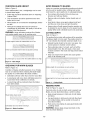
Operator's
Manual
8"JOINTER AND
JOINTER STAND
Model No.
351.21 7030
CAUTION:
Read and follow
all Safety Rules and Operating
Instructions before First Use
of this Product.
Sears, Roebuck and Co., Hoffman
www.sears.com/craftsman
23056.00 Draft (01/21/05)
Estates, IL 60179 U.S.A.
PREPARE
Warranty
....................................
SafetyRules...............................
Unpacking..................................
Assembly.................................
Installation
.................................
KnowYourJointer............................
Operation................................
Maintenance
................................
Troubleshooting
.............................
PartsIllustration
andList ...................
2
2-3
3
3-5
5-6
7
7-11
11
12
14-19
Keep work area clean. Cluttered work areas invite
accidents.
•
Do not use power tools in dangerous environments.
•
Do not use power tools in damp or wet locations. Do
not expose power tools to rain.
•
Work area should be properly lighted.
•
Proper electrical receptacle should be available for
tool. Three prong plug should be plugged directly
into properly grounded, three-prong receptacle.
•
Extension cords should have a grounding prong and
the three wires of the extension cord should be of
the correct gauge.
•
Keep visitors at a safe distance from work area.
•
Keep children out of workplace. Make workshop childproof. Use padlocks, master switches or remove switch
keys to prevent any unintentional use of power tools.
TOOL SHOULD
If this product is used for commercial or rental purposes, this warranty will apply for 90 days from the date of
purchase.
This warranty applies only while this product is used in
the United States.
Always unplug tool prior to inspection.
•
Consult manual for specific maintaining and adjusting procedures.
•
Keep tool lubricated and clean for safest operation.
•
Remove adjusting tools. Form habit of checking to
see that adjusting tools are removed before switching machine on.
•
Keep all parts in working order. Check to determine
that the guard or other parts will operate properly
and perform their intended function.
•
Check for damaged parts. Check for alignment of
moving parts, binding, breakage, mounting and any
other condition that may affect a tool's operation.
•
A guard or other part that is damaged should be
properly repaired or replaced. Do not perform
makeshift repairs. (Use parts list provided to order
replacement parts.)
WARNING:
For your own safety, read all of the rules
and precautions before operating tool.
KNOW HOW TO USE TOOL
CAUTION: Always follow proper operating procedures
as defined in this manual even if you are familiar with
use of this or similar tools. Remember that being careless for even a fraction of a second can result in severe
personal injury.
BE PREPARED
BE MAINTAINED
•
This warranty gives you specific legal rights, and you
may also have other rights which vary from state to state.
Sears, Roebuck and Co., Dept. 817WA, Hoffman
Estates, IL 60179
AREA FOR JOB
•
FULL ONE YEAR WARRANTY
If this product fails due to a defect in material or workmanship within one year from the date of purchase, Sears will
at its option repair or replace it free of charge. Contact
your nearest Sears Service Center (1-800-4-MY-HOME)
to arrange for product repair, or return this product to
place of purchase for replacement.
WORK
•
Use right tool for job. Do not force tool or attachment
to do a job for which it was not designed.
•
Disconnect tool when changing blades.
•
Avoid accidental start-up. Make sure that the switch
is in the OFF position before plugging in.
•
Do not force tool. It will work most efficiently at the
rate for which it was designed.
•
Keep hands away from moving parts and cutting
surfaces.
FOR JOB
•
Wear proper apparel. Do not wear loose clothing,
gloves, neckties, rings, bracelets or other jewelry
which may get caught in moving parts of machine.
•
Wear protective hair covering to contain long hair.
•
Wear safety shoes with non-slip soles.
•
•
Wear safety glasses complying with United States
ANSI Z87.1. Everyday glasses have only impact
resistant lenses. They are NOT safety glasses.
Never leave tool running unattended. Turn the power
off and do not leave tool until it comes to a complete
stop.
•
Do not overreach. Keep proper footing and balance.
•
Wear face mask or dust mask if operation is dusty.
•
•
Be alert and think clearly. Never operate power tools
when tired, intoxicated or when taking medications
that cause drowsiness.
Never stand on tool. Serious injury could occur if tool is
tipped or if blade is unintentionally contacted.
•
Know your tool. Learn the tool's operation, application
and specific limitations.
© Sears, Roebuck and Co.
2
• Userecommended
accessories
(referto page19).
Useofimproperaccessories
maycauseriskof
injuryto persons.
• Handleworkpiececorrectly.
Protecthandsfrompossibleinjury.
• Turnmachineoff if itjams.Bladejamswhenit digs
toodeeplyintoworkpiece.
(Motorforcekeepsit
stuckinthe work.)
CAUTION:Thinksafety!Safetyis a combination
of
operatorcommonsenseandalertnessatalltimes
whentoolis beingused.
G
[
Referto Figure1.
Checkforshippingdamage.If damagehasoccurred,a
claimmustbefiledwithcarrier.Checkforcompleteness.Immediately
reportmissingpartsto dealer.
Thejointeris shippedcompletein onecratealongwith
a cartonforthestand.Additionalpartswhichneedto
befastenedtojointerandjointerstandshouldbelocatedandaccounted
forbeforeassembling.
A. Jointer
B. Stand
C. Fence
D. FenceBracketAssembly
E. FenceLockingHandle
E PushBlock(2)
G. PushBlockHolder
H. BladeGauge
I. BladeGuardAssembly
J. BeltGuard
K. LockingStuds(3)
L. Handwheel
Assembly
(2)
M.DustPort
N. V-Belt(2)
AngleGauge(NotShown)
Hardware
Bag(PartNo.23200.00)
includesFenceGrip
Handle,M10FlatWasher(3),M10LockWasher(3),
M5x 10SocketHeadBolt(4),M5FlatWasher(4),5 x
5 x 25mmKey(2),3,4 and5mmhexwrenches,
8/10mm,12/14mm
and17/19mm
openendwrenches.
IMPORTANT:
Tableis coatedwitha protectant.
To
ensureproperfit andoperation,removecoating.
Coatingis easilyremovedwithmildsolvents,suchas
mineralspirits,anda softcloth.Avoidgettingsolution
onpaintor anyofthe rubberor plasticparts.Solvents
maydeteriorate
thesefinishes.Usesoapandwateron
paint,plasticor rubbercomponents.
Aftercleaning,
coverallexposedsurfaceswitha lightcoatingof oil.
Pastewaxis recommended
fortabletops.
WARNING:Neverusehighlyvolatilesolvents.Nonflammable
solventsarerecommended
toavoidpossible
firehazard.
E /
M
[
:igure 1 - Unpacking
CAUTION: Do not attempt assembly if parts are missing. Use this manual to order replacement parts.
JOINTER
INSTALLATION
Refer to Figure 2.
Before jointer or stand are assembled, a suitable location should be chosen. The jointer and jointer stand
weigh approximately 400 Ibs when completely assembled. They should be assembled on location.
•
Jointer needs to be set on a flat, level surface.
•
Make sure there is ample room on either side of
jointer to accommodate desired workpiece size.
•
Good lighting and correct power supply are also
required for a proper work area.
•
Place stand in its designated spot. Door panel for
access to motor is on back side.
.._e_Blade
Guard Assembly
T-Handle Bolt
\
Key
Handwheel
Screw
Flat Washer
Lock Washer
Locking Stud
=igure 2 - Jointer Assembly
MOUNT
JOINTER
MOUNT
BLADE
GUARD
Refer to Figure 2, page 3.
Refer to Figures 2 and 3, pages 3 and 4.
•
•
Jointer is held to stand by three locking studs, three
lock washers and flat washers.
The blade guard assembly employs a spring loaded
return located between the blade guard and guard
shaft. Blade guard assembly can be attached or
removed without altering spring action.
•
Threaded mounting holes in base of jointer must be
lined up with holes in top of stand. Using a flashlight
will assist in quickly locating the holes.
The infeed table includes a mounting block which is
part of the casting. Insert guard shaft into the mounting block.
•
One location for a stud which fastens the jointer to
stand is reached through the chip chute.
Position blade guard assembly with spring pin facing
toward front of infeed table (see Figure 3).
•
Secure in position with T-handle bolt.
•
Tension will be applied to guard when fence is installed.
Place jointer on stand and attach it.
NOTE: At least two people are required to lift the 300
lb. jointer.
•
•
•
•
Location for other two locking studs are reached
through the doorway of the stand.
INSTALL V-BELTS
Refer to Figure 12.
Jointer uses a two-belt system for more efficient power
transfer. Motor mounting plate pivots at one side to provide for easy mounting and easy belt tensioning.
•
Loosen front bolts (Key No. 11) so that motor
mounting plate (Key No. 9) is loose.
NOTE: The front bolts are located in the slotted end
of the plate.
•
Pull up on motor mounting plate and install V-Belts
onto driven pulley and motor pulley.
•
Apply tension to the belts by pushing down on plate
and tightening bolts.
•
Make sure belts are tensioned properly. Belt is properly tensioned when moderate pressure applied to
the belts (between the pulleys) will deflect the belts
about '/2".
•
Figure 3 - Install Blade Guard
MOUNT
•
Loosen the two socket head bolts (Key No. 41) of the
outfeed table. Do not remove bolts. Loosen just
enough to fit bracket over bolts.
•
Place the fence bracket assembly over the bolts.
Carefully tighten bolts, making sure to keep the top
surfaces of the fence bracket assembly and outfeed
table flush to each other.
HANDWHEELS
Handwheels attach to the leadscrews for table height
adjustment. The leadscrew is coupled to the handwheel with a key.
Loosen and remove screw and flat washer from
leadscrew.
•
•
Place key into keyway on the leadscrew.
Slide handwheel onto leadscrew.
•
Fasten handwheel to leadscrew with screw and flat
washer.
MOUNT
MOUNT
•
Swing blade guard forward, over and past cutterhead.
Secure in position.
•
Loosen hex nuts (Key No. 6) several turns.
•
Position fence in front of the link (Key No. 10). Make
sure blade relief in fence is against the table, over
the cutterhead.
•
Turn the cone point set screws (Key No. 7) equally
until they seat firmly in the pivot connectors
(Key No. 5).
•
Check that fence is parallel to both jointer tables. If
not parallel, loosen set screws, turn pivot connector
as needed, and then tighten set screws into pivot
connectors.
Refer to Figure 13.
Loosen and remove two bolts and washers (Key
Nos. 8 and 44) on the back of the jointer base.
•
Position belt guard (Key No. 15) on back of jointer
and secure in position with bolts and washers.
FENCE TO BRACKET
Refer to Figures 4 and 14, pages 5 and 19.
BELT GUARD
•
ASSEMBLY
•
Refer to Figure 2, page 3.
•
BRACKET
Refer to Figure 13.
If belts do not have the proper tension, the motor
mounting plate can be adjusted by loosening front
bolts. Move plate, tighten bolts and recheck belt
tension.
MOUNT
FENCE
4
•
Secure set screws by tightening hex nuts.
•
Remove hex head packing bolt from top of fence
bracket assembly and discard. Insert fence angle
lock handle and thread into nut. Make sure nut is
aligned in bracket slot.
•
Remove socket head bolt from fence block (Key No.
16). Insert bolt through fence and thread bolt securely into block.
•
Attach fence grip (Key No. 3) to fence.
•
Release blade guard. Blade guard should swing
against fence and completely cover cutterhead.
burnout. Heavy loads require that voltage at motor
terminals be no less than the voltage specified on
nameplate.
GROUNDING
INSTRUCTIONS
WARNING:
Improper connection of equipment
grounding conductor can result in the risk of electrical
shock. Equipment should be grounded while in use to
protect operator from electrical shock.
Check with a qualified electrician if grounding instructions are not understood or if in doubt as to whether the
tool is properly grounded.
This tool is equipped with an approved 3-conductor
cord rated up to 250V and a 3-prong grounding type
plug rated at 250V (See Figure 5) for your protection
against shock hazards.
Do not remove or alter grounding prong in any manner.
In the event of a malfunction or breakdown, grounding
provides a path of least resistance for electrical shock.
WARNING:
Do not permit fingers to touch the terminals of plug when installing or removing from outlet.
Figure 4 - Mounting
MOUNT
gle
Lock Handle
(Packing Bolt
Removed)
Fence to Bracket
DUST COLLECTION
Grounding Pin
PORT
Refer to Figure 2.
:igure 5 - Grounding
•
Jointer stand has a built-in chip chute. The dust
collection port covers the end of the chip chute.
•
Attach port with pan head screws and flat washers.
•
Port has a 4" diameter opening to attach to a standard hose.
Plug must be plugged into a 230V matching outlet (See
Figure 5) that is properly installed and grounded in accordance with all local codes and ordinances. Do not modify
plug provided. If it will not fit in outlet, have proper outlet
installed by a qualified electrician.
•
Port will not inhibit the chip flow. A dust collector
must be used.
Inspect tool cords periodically, and if damaged, have
repaired by an authorized service facility.
ATTACH PUSH BLOCK SHELF
Refer to Figure 12.
•
•
Place shelf (Key No. 29) over bolt and washer (Key
Nos. 17 and 27) located on stand beneath infeed
table.
Tighten bolt to secure shelf in position.
Methods
Green (or green and yellow) conductor in cord is the
grounding wire. If repair or replacement of the electric
cord or plug is necessary, do not connect the green (or
green and yellow) wire to a live terminal.
Where a 2-prong wall
must be replaced with
receptacle installed in
Code and local codes
receptacle is encountered, it
a properly grounded 3-prong
accordance with National Electric
and ordinances.
WARNING: This work should be performed by a
qualified electrician.
POWER
SOURCE
Refer to Figure 5.
WARNING:
Do not connect jointer to the power
source until all assembly steps have been completed.
The motor is designed for operation on the voltage and
frequency specified. Normal loads will be handled
safely on voltages not more than 10% above or below
specified voltage. Running the unit on voltages which
are not within range may cause overheating and motor
EXTENSION
•
•
•
CORDS
The use of any extension cord will cause some drop
in voltage and loss of power.
Wires of the extension cord must be of sufficient size
to carry the current and maintain adequate voltage.
Use the table to determine the minimum wire size
(A.W.G.) extension cord.
•
•
Use only 3-wire extension cords having 3-prong
grounding type plugs and 3-pole receptacles which
accept the tool plug.
-q
If the extension cord is worn, cut, or damaged in any
way, replace it immediately.
EXTENSION CORD LENGTH
Wire Size
A.W.G.
Up to 50 ft ..................................
12
White
NOTE: Using extension cords over 50 ft. long is not
recommended.
_
White
MOTOR
The stand is assembled with motor and wiring installed.
The 230 Volt AC capacitor start motor has the following
specifications:
Horsepower
.................................
Voltage ...................................
Amperes ..................................
Hertz .....................................
Phase ..................................
RPM ....................................
ELECTRICAL
2
230
8.6
60
Black
Single
3450
Figure 6 - Wiring Schematic
CONNECTIONS
OVERLOAD
Refer to Figure 6.
PROTECTION
The magnetic contactor has overload protection that
helps to prevent damage to the motor. The overload
protection will automatically turn off the magnetic contactor when an overload occurs. Be sure to disconnect
jointer from power source when resetting overload protector. The protection is reset by opening the contactor
box and pressing the reset button.
WARNING:
All electrical connections must be performed by a qualified electrician. Make sure unit is off
and disconnected from power source while motor is
mounted, connected, reconnected or anytime wiring is
inspected.
Jointer has an approved 230 volt three-conductor line
cord with a three-prong grounding type plug, and a 230
volt magnetic contactor that is prewired in the factory
(See Figure 6).
•
Black
CHECK
Connect jointer to a supply circuit protected by a 20
AMP circuit breaker or time delay fuse.
6
CONNECTIONS
•
Plug in the line cord to a 230 volt power source.
•
Turn and release the emergency stop button.
•
Depress the start button. The motor must rotate
counterclockwise facing shaft end.
•
Depress the stop button. The motor must stop.
•
Depressing the start button with the emergency stop
button pressed down must not start the motor.
•
If any of the above steps do not work properly, disconnect jointer from power source and recheck the
connections.
lO
\
11
\
12
1 Stand
8 Fence
2
Push Blocks
9 Fence Grip
3
4
5
6
Start/Stop Switch
Emergency Stop Switch
Depth Scale and Limit Stop
Infeed Table Hand Wheel
7
Infeed Table
10 Fence Angle Lock Handle
11 Outfeed Table
12 Outfeed Table Hand Wheel
13 Dust Collection Port
SPECIFICATIONS
Table size ............................
Refer to Figures 7-14, pages 8-10 and 19.
Craftsman 8" Jointer is used to surface the faces and
edges of boards, produce a flat surface on warped
boards and shape rabbets, bevels, chamfers and
tapers. The jointer features heavy cast iron infeed and
outfeed tables with precision ground work surfaces and
leadscrews for precise table height adjustments. Rigid,
center mount guide fence is fully adjustable and is provided with positive stops at 45, 90, and 135 ° positions.
Jointer Stand includes chip chute with 4" adapter for
dust collection and safety electrical control that reduces
the risk of accidental start-up. Includes 2 HE 3450 RPM
motor.
701/2x 91/4
''
Fence size .............................
Blade size (3) ......................
Maximum cut .........................
Overall dimension .................
Dust collection port ...................
Motor ..........................
40 x 5"
81/4x 15/1_
x 1/8"
1/8" Deep
961/4x 25 x 36"
4" Diameter
2HP, 3450 RPM
Jointing: This is a surfacing operation in which a small
amount of wood is removed from the edges and faces
of boards to get smooth, straight and even surfaces,
such that two edges running across the planing blades
would fit together perfectly, forming a seamless joint.
•
Do not perform jointing operations on material shorter than 10", narrower than 3/4",or less than 1/41'
thick.
•
Never make jointing cuts deeper than W'.
•
Always keep cutter head and blade guards in proper
working condition.
• Maintaintheproperrelationships
ofinfeedandoutfeedtablesurfacesandcutterheadbladepath.
• Donotbacktheworktowardtheinfeedtable.
• Supporttheworkpiece
adequately
atall timesduring
operation;
maintaincontroloftheworkpiece.
• Usehold-down/push
blocksforjointingmaterial
narrowerthan3".
• Donotattemptto performanabnormalor littleused
operation
withoutstudyandtheuseofadequate
hold-down/push
blocks,jigs,fixtures,stops,andthe
like.
WARNING:Somedustcreatedbypowersanding,
sawing,grinding,drillingandotherconstruction
activitiescontainschemicals
knowntocausecancer,birth
defectsor otherreproductive
harm.
Someexamples
of thesechemicals
are:
• Leadfromlead-based
paints.
• Crystalline
silicafrombricksandcementandother
masonryproducts.
• Arsenicandchromium
fromchemically-treated
lumber.
Yourriskfromtheseexposures
vary,depending
on how
oftenyoudothistypeofwork.Toreduceyourexposure
tothesechemicals:
workin a wellventilatedareaand
workwithapproved
safetyequipment.
Alwayswear
MSHA/NIOSH
approved,
properlyfittingfacemaskor
respiratorwhenusingsuchtools.
TheCraftsman
jointercanproducea smoothsurfaceon
anylumber.Precision
of cutwillonlybeasaccurateas
thesettings.
OPERATING
Figure 7b - On and OFF Switches
POSITIONING
Refer to Figures 8 (page 9) and 15.
•
Fence is usually set at 90 ° to the table for producing
square lumber.
•
Fence can be positioned anywhere from an inward
45 ° to an outward 45 °.
•
The angle position is locked by fence angle lock
handle (Key No. 19).
•
Fence grip (Key No. 3) is used to change the fence
angle.
•
Collar (Key No. 12) should be adjusted to stop the
fence at the inward 45 ° position.
- Use angle gauge provided to check or set the
inward 45 ° position.
CONTROLS
- Make sure the position of collar is locked with set
screw (Key No. 13).
ON, OFF AND EMERGENCY STOP SWITCHES
•
Refer to Figure 7.
•
•
The Emergency Stop Switch is located to the right of
the ON and OFF switches.
ON switch is green and marked 'T', OFF switch is
red and marked "0".
•
Pressing the Emergency Stop or OFF will turn off
the machine. The Emergency Stop Switch will need
to be twisted and released before the jointer can be
restarted.
The 90 ° position is stopped when socket head bolt
(Key No. 2) contacts stop plate (Key No. 22).
- The stop plate must be in the DOWN position to
make contact with bolt.
Push the switch cover UP to access the ON and
OFF switches.
•
FENCE
- Use angle gauge provided to check or set the
90 ° position.
- Make sure the position of the bolt is locked with
nut (Key No. 9).
•
The outward 45 ° (135 °) position is stopped by the
hex bolt (Key No. 8).
CAUTION:
Make sure the stop plate (Key No. 22) is in
the UP position (vertical) before attempting to set fence
at outward 45 ° (135 °) position.
- Use angle gauge provided square to check or set
the outward 45 ° (135 °) position.
- Make sure position of stop is locked with nut
(Key No. 9).
•
Fence can be positioned to expose desired length of
blade.
- Guide position is fixed by fence slide lock handle
(Key No. 19).
Figure 7a - Emergency Stop and Switch
- When moving fence, lift with the grip (Key No. 3)
while pulling T-bolt handle (Key No. 19) to avoid
dragging the fence on the table.
Cover
8
90° Limit Plate in
Down Position
90° Limit Bolt
and Nut
135° Limit
Bolt and Nut
•
Lower the infeed table as far as it will go.
•
Place the blade gauge so that it rests on the cutter
head and straddles the blade.
•
Loosen the five locking bolts (Key No. 6).
•
Press the blade gauge firmly against the cutter head
and make sure that the blade touches the contact
points.
\
sS
y
45° Limit
Collar
Fence Slide
Lock Handle
•
Tighten the bolts to secure the blade in position.
RABBETING
The jointer blades have a second blade on the outward
radial edge. These edges must also be aligned to perform rabbeting.
•
Make sure blades protrude the same distance from
end of cutter head. The blades should not protrude
more than 1/8".
•
Use the blade gauge when repositioning blades to
keep them adjusted as described in "Adjusting Blade
Height".
•
By repositioning the infeed table and fence, a wide
range of rabbet joints can be cut.
TABLE MOTION
Refer to Figure 14.
Both the infeed and outfeed table use a leadscrew,
guided by adjustable wear plates.
•
Release the position locking by loosening the
T-handle bolt (Key No. 43).
•
Raise and lower the table by turning handwheel (Key
No. 31 ).
•
Make sure that action is constant for entire length of
travel. There should be a slight drag.
•
To adjust drag loosen set screws and nuts (Key Nos.
27 and 42). Adjust set screws until a slight drag on
table action is felt. Then hold set screw in position
and tighten nut.
•
If blade does not touch contact points or gauge does
not touch cutter head, use the jack screws (Key No. 4)
to adjust blade accordingly.
Fence Angle
Hock Handle
Figure 8 - Fence Positioning and Stops
ADJUSTING
•
After drag is adjusted and table is in desired position, secure table in position by tightening T-handle
bolt.
POSITIONING
INFEED TABLE
Refer to Figure 14.
WARNING:
Rabbeting requires removal of blade guard.
Blade guard must be replaced correctly when rabbeting
is completed. (See Assembly, "Mount Blade Guard")
ADJUSTING
•
Positive stop prevents the table from being lowered
more than '/8" (Key No. 16).
•
Table can be lowered past the stop (for rabbeting
operation, etc.) by simultaneously pulling knob outward and turning table handwheel.
ADJUSTING
BLADE
HEIGHT
Refer to Figure 14.
To produce an even surface on a workpiece, the blade
edges must be the same distance from axis of cutter
head. A blade gauge (Key No. 60) has been provided to
make blade height adjustment easy.
TABLE
The outfeed table supports the wood after it has been
cut. Outfeed table will be set about .003" below the
level of blade edge. The wood is compressed at the cut
and the outfeed table must be adjusted to compensate
for it.
•
Raise outfeed table above height of blade.
•
Position one blade edge point to the highest point on
its path.
•
Rest a straightedge on the table.
•
Lower outfeed table until blade and straightedge
contact.
•
Gently rotate cutter head and allow it to move the
straightedge. Blade should pull the straight edge with
out visibly lifting it from the table.
•
Make sure all blades move the straightedge the
same amount. Also check both sides of blade. If all
blades do not line up, blade height should be readjusted.
•
Lock outfeed table position with the T-handle bolt
(Figure 14, Key No. 43). Position should not need to
be changed.
•
Proper adjustment of outfeed table can also be
determined by examining the cut (See Figure 9,
page 10).
The position of infeed table determines depth of cut.
Infeed table also needs to be lowered to make certain
adjustments.
OUTFEED
CHECKING
BLADE
HEIGHT
AVOID DAMAGE
Refer to Figure 9.
Once outfeed table is set, a straightedge
to check blade height.
TO BLADES
Jointer is a precision woodworking machine and should
only be used on quality lumber. Jointing bad lumber
could result in a poor quality cut on subsequent pieces.
can be used
•
Follow the procedure described above in "Adjusting
Outfeed Table".
•
Do not plane dirty boards. Dirt and stones are
abrasive and will wear blades.
•
This examination should be performed each time
before unit is used.
•
Remove nails and staples. Jointer should only cut
wood.
•
When blades do not contact the straightedge, blades
are dull.
•
Avoid knots. Heavy cross-grain makes knots hard
and they can come loose and jam the jointer.
•
Although the outfeed table may be lowered to
compensate for dull blades, the quality of cut will be
reduced (See Maintenance).
•
Assess value of badly warped boards; operator can
be tempted to use too deep of cut to square boards
quickly. When work is finished board is not useful size.
WARNING:
Using dull blades reduces life of blades
and creates greater wear on all machine parts.
CUTTING
DEPTH
Refer to Figure 11.
The surface that a jointer will produce will be smoother
if shallower depth of cut is used. The positive stop for a
1/8" cut indicates the intended maximum depth of cut.
snipe happens when the outfeed table is too low.
• Warped boards should not be cut in one pass. Use
several passes to maintain a level surface.
•
Plane alternate sides of a board, each at half the
desired depth of cut; this will create a more even
moisture content in the wood and help prevent future
warpage.
•
Deep cuts require more power and cause greater
wear on all machine parts.
level cut indicates that the table is adjusted correctly.
L
curved taper cut occurs when the outfeed table is too high.
igure 9 -Table Height
CHECKING
FOR WORN
BLADES
Shallow depth of cut produces an even surface.
Refer to Figure 10.
Condition of blades will affect precision of cut. If blade
wear is not observed when checking the blade height,
the quality of cut will indicate the blade condition.
• Dull blades will tear rather than sever the wood fiber.
•
A raised grain will occur when dull blades pound on
wood where there is difference in density.
_arger depth of cut uses more power and reduces quality of
sut.
•
A raised ridge will be produced where the blades
have been nicked.
Figure 11 - Cutting Depth
FEEDING
WORK
Refer to Figure 12, page 11
Feed rate refers to rate at which wood is passed over
blades. An even feed will produce a uniform surface.
3harp blades shave wood.
Dull blades tear wood while removing it.
•
Keep enough pressure to hold work to both tables
and fence.
•
Use push blocks to hold wood onto both the infeed
and outfeed tables and be careful not to push on
wood above blades.
•
Push work across blades by using push blocks with
a walking motion.
WARNING: Always keep at least one block on the
wood to prevent kickback.
=igure 10 - Blade Condition
10
•
•
Support work on both infeed and outfeed tables.
Over half the board must rest on tables before and
after cut to keep wood from tilting off table. Use roller
extension or stand when long boards are jointed
(See Recommended Accessories, page 19).
•
- Partially cover the stone with paper to protect the
table top.
- Position infeed table so stone will contact blade
along its beveled surface.
- Stroke the stone across blade from one side to
Feed wood in grain direction (See Figure 11). Wood
fed against grain will result in chipped and splintered
edges. Sometimes grain will switch direction in the
middle of a length of board. If possible, cut board
before jointing.
other while stone is also moved slightly in the
direction of feed.
- Make sure to do the same number of strokes on
each blade.
•
Grain
Blades can be kept sharp by whetting them with a
fine sharpening stone.
Grain
Blades that are noticeably nicked or worn must be
resurfaced to a new beveled edge. Remove blades
(one at a time).
- Lower infeed table.
- Hold blades with blade gauge.
- Loosen bolts (Figure 14, Key No. 6).
- Remove blade.
NOTE: Many shops do not have capability to resurface
blades. Yellow Pages should list Sharpening Services or
Tool Grinding.
•
Grain
Grain
Sometimes replacing blades is less expensive than
resurfacing them. Keeping a spare set of blades on
hand is recommended. Blades should always be
sharpened or replaced in sets of three.
LUBRICATION
--igure 12 - Direction of Grain
Jointer will operate best if it is kept in good operating
condition. Keep unit adjusted as described in
"Operation." Also, blades must be kept clean and sharp
to ensure quality of cut and efficiency of operation.
WARNING:
Make certain that unit is disconnected
BLADE CARE
•
Motor and cutter head bearings are sealed and need
no lubrication.
•
Fence guide and table leadscrews should be
cleaned of debris and greased as needed.
•
Occasionally apply a few drops of light machine oil
to gibs to keep tables sliding free in relation to base.
MACHINED
from power source before servicing.
•
•
Gum and pitch will collect on blades and cause
excess friction when working.
Blades will overheat and wear at an accelerated
rate. Use a gum and pitch remover to keep blades
clean.
11
SURFACES
•
Surface of tables and fence should be kept smooth
and clean for easy work feed.
•
Apply a paste wax to surfaces to keep them slick
and to prevent corrosion.
SYMPTOM
POSSIBLE
Snipe gouging at ends of
board)
1. Dull Blades
1. Replace or sharpen blades;
See "Blade Care", page 11
2. inadequate support of long boards
3. Uneven feed
2. Support long boards
3. See "Feeding Work", page 10
4. Outfeed table is not aligned
5. Extension rollers misaligned
4. Check outfeed table position
5. Adjust extension rollers
Fuzzy grain
1. Planing wood with a high moisture
1. Remove high moisture content from
wood by drying
Torn grain
1. Too heavy a cut
2. Blades cutting against grain
3. Dull blades
1. See "Cutting Depth", page 10
2. See "Feeding Work", page 10
1. Dull blades
2. Too heavy a cut
1. Replace or sharpen blades;
See "Blade Care", page 11
2. Review "Cutting Depth", page 10
3. Moisture content too high
3. Dry wood or use dry wood
Uneven depth of cut,
side to side
1. Blade height not uniform
2. Fence not perpendicular to
jointer bed
1. See "Adjusting Blade Height", page 9
Table elevation adjusts
with difficulty
1. Wear plate not adjusted
1. Adjust wear plates
2. Leadscrew dirty
3. Leadscrew worn
2. Clean and lubricate leadscrews
Rough raised grain
Depth of cut does not
match scale
Will not start/reset
CAUSE(S)
ACTION
3. Replace or sharpen blades
See "Blade Care", page 11
2. See "Positioning Fence, page 8
4. Friction between base and tables
3. Replace leadscrew
4. Clean, lubricate
1. Indicator not set correctly
1. Adjust indicator, securely tighten
2. Blade projection incorrect
2. Set blade projection correctly;
See "Adjusting Blade Height', page 9
1. Not plugged in
2. Circuit breaker/fuse
1. Check power source
2. Check power source, replace fuse
3. Have motor checked by qualified electrician
3. Motor failure
4. Loose wire
5. Contactor overload tripped
Motor stoppage. Fuses are
blown or circuit breakers are
CORRECTIVE
4. Having wiring checked by a
qualified electrician
5. Have qualified electrician replace
6. Contactor overload tripped
6. Reset contactor overload by pressing
reset button on contactor
1. Unit overload
1. Reduce load
2. Fuses or circuit breakers do not
have sufficient capacity
2. Connect unit to circuit with
adequate amp rating or install
proper size fuses or breakers
3. Reduce the load. Do not use other
tripped repeatedly
3. Circuit overload
appliances or motor on same circuit
when using jointer
90 ° and 45 ° cuts inaccurate
1. Fence stops not adjusted properly
1. Adjust fence stops. See "Positioning Fence",
page 8.
2. Fence bottom not even with
outfeed table due to wood chips
under fence
2. Clean wood chips from underside of fence.
12
NOTES
13
Model 351.217030
Figure
13 - Replacement
Parts Illustration
for Stand
12
\
23
18
.
/
27
28 27
22
/
21
19
/
i
29
[
25
6
26
/
t
l
33
I
[
t
34
31
11
_"_32
14
13
9
KEY
NO.
PART NO.
DESCRIPTION
QTY.
1
N/A
Stand
1
2
23202.00
Door
1
3
23203.00
Knob
2
4
23204.00
Latch
2
5
STD840812
8-1.25mm Hex Nut*
6
STD851008
8mm Flat Washer*
7
STD851010
10ram Flat Washer*
3
8
23205.00
Locking Stud
3
9
23206.00
Motor Mounting Plate
1
10
23207.00
16311.00
Motor (Includes Key No. 15)
12-1.75 x 25mm Socket Head Bolt
1
11
12
23278.00
V-Belt
2
13
STD851012
12mm Flat Washer*
4
14
STD870840
8-1.25 x 40ram Socket Head Bolt*
4
15
23277.00
Capacitor 200MFD
1
16
STD852008
8mm Lock Washer*
4
17
STD863508
5-0.8 x 8mm Pan Head Screw*
6
18
01516.00
5-0.8 x 8mm Set Screw
1
6
16
4
19
23208.00
Motor Pulley
1
20
23209.00
1
21
23210.00
8 x 7 x 32mm Key
Cover
22
23211.00
Cover
1
23
23212.00
Push Block
2
24
23213.00
Line Cord
1
25
23214.00
STD863520
3.5 x 9.5mm Threadforming Screw
5-0.8 x 20mm Pan Head Screw*
3
26
27
STD851005
5mm Flat Washer*
4
28
STD840508
5-0.8ram Hex Nut*
2
29
23215.00
1
30
23216.00
Storage Shelf
Strain Relief
31
STD863416
4-0.7 x 16mm Pan Head Screw*
2
32
23217.00
Dust Collection Port
1
33
23218.00
1
34
23219.00
Emergency Stop Switch
On/Off Switch
A
23056.00
Operator's Manual
1
*
N/A
A
1
2
1
1
Standard hardware item available locally
Not available as replacement part
Not shown
15
Model 351.217030
Figure
14 - Replacement
Parts Illustration
for Jointer
6
/
32
12
24
13
41
9
22
23
1
9
35
\
_53
43
18
I
26
30
3_
25
38
33
9
41
31
16
KEY
NO. PART NO.
DESCRIPTION
QTY.
KEY
NO. PART NO.
DESCRIPTION
QTY.
1
23240.00
Bearing Housing
2
28
08634.00
4 x 12mm Spring Pin
1
2
STD315241
STD870616
6-1.0 x 16mm Socket Head Bolt*
2
23241.00
2
1
29
3
6204ZZ Ball Bearing*
Cutter Head
3O
STD851006
6ram Flat Washer*
2
4
23242.00
Jack Screw
6
31
23257.00
Handwheel Assembly
2
5
23243.00
Blade Lock Bar
3
32
23275.00
6
23244.00
Blade Lock Bolt
12
33
23259.00
Blade Gauge Assembly
Collar
1
2
7
23245.00
06983.00
6-1.0 x 8ram Set Screw
4
02661.00
1
2
34
8
Blade (Set of 3)
8-1.25 x 14ram Socket Head Bolt
35
23276.00
Shoulder Bracket
2
9
STD852010
10mm Lock Washer*
10
36
STD851010
10mm Flat Washer*
8
10
STD841010
10-1.5mm Hex Nut*
2
37
07186.00
10-1.5 x 30ram Socket Head Bolt
4
11
23246.00
Threaded Stud
2
38
23260.00
Table Arm
1
12
00975.00
5 x 5 x 25ram Key
1
39
23261.00
Leadscrew
2
13
23247.00
1
1
23262.00
Leadscrew Bracket
2
01516.00
Driven Pulley
5-0.8 x 8mm Set Screw
4O
14
41
05367.00
10-1.5 x 40ram Socket Head Bolt
4
15
23248.00
Belt Guard
1
42
23263.00
8-1.25 x 40ram Set Screw
4
16
23255.00
1
3
23264.00
T-Handle Bolt
3
STD870816
Depth Stop Assembly
8-1.25 x 16ram Socket Head Bolt*
43
17
44
STD851008
8ram Flat Washer*
2
18
23249.00
Infeed Table
1
45
23265.00
Wear Plate
2
19
N/A
Base
1
46
STD863506
5-0.8 x 6ram Pan Head Screw*
1
20
23266.00
Scale
1
47
23268.00
Blade Guard with Label
1
21
23267.00
Pointer
1
48
00519.00
3AM1-12 Retaining Ring
1
22
23272.00
Outfeed Table
1
49
23269.00
Spring
1
23
23273.00
Fence Guide Table
1
50
07825.00
6 x 35mm Spring Pin
1
24
23274.00
Guide Bar
1
51
02752.00
25
23256.00
5 x 5 x 32ram Key
1
52
23270.00
6 x 40mm Spring Pin
Guard Shaft
1
1
26
01900.00
4
4
23271.00
Blade Guard Assembly
STD840812
3AMI-25 Retaining Ring
8-1.25mm Hex Nut*
53
27
*
N/A
Standard hardware item available locally
Not available as replacement part
(incl. Key Nos. 47-52)
17
1
Model 351.217030
Figure
15 - Replacement
Parts Illustration
for Fence
8
29
8
27
/
8
6
10
15
\
\
\
17
\
\
18
26
14
\
11
20
\
\
24
18
21
19
\
x
\
4
/
25
18
\
KEY
NO.
PART NO.
DESCRIPTION
QTY.
1
23221.00
Fence
1
2
STD870840
8-1.25 x 40mm Socket Head Bolt*
2
3
23223.00
1
4
23239.00
Fence Grip
Shoulder Bolt
5
23224.00
Pivot Connector
2
6
STD841010
10-1.5mm Hex Nut*
4
7
23403.00
10-1.5 x 40ram Cone Point Set Screw
4
8
STD870820
8-1.25 x 20mm Socket Head Bolt*
3
9
STD840812
8-1.25mm Hex Nut*
2
10
23225.00
Link
1
11
STD841217
12-1.75mm Hex Nut*
2
12
23226.00
Collar
1
13
06983.00
6-1.0 x 8mm Set Screw
1
14
23227.00
Plate
1
15
23228.00
Adjustment
16
23229.00
Fence Block
1
17
23230.00
1
18
STD851012
Clamp
12ram Flat Washer*
1
1
Bar
3
19
23231.00
T-handle Bolt
2
2O
23232.00
Fence Guide Box
1
21
08634.00
4 x 12ram Spring Pin
3
22
23233.00
23234.00
Stop Plate
Bolt
1
23
24
23235.00
1
25
23236.00
Connecting Block
Nut
26
23237.00
Sleeve
1
27
STD851010
10mm Flat Washer*
4
28
STD851008
8mm Flat Washer*
2
29
23284.00
Guard
1
A
23238.00
Angle Gauge
1
*
A
1
1
Standard hardware item available locally
Not shown
Recommended
Accessories
A
Roller Table
9-22242
A
Support Stand
9-21417
A
Push Block Set
9-23000
19
® Registered
Trademark
/
TM
Trademark
/
Sh4
Service
Mark of Sears,
Roebuck
and Co.
® Marca Registrada / TM Marca de F_brica / SM Marea de Servicio de Sears, Roebuck
MC Marque de commerce / MD Marque d_pos_e de Sears, Roebuck and Co.
and Co.
© Sears,
Roebuck
and Co.