1
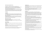
vmp series
valve microphone preamplifiers
Thankyou for purchasing a Sebatron unit. We are sure
it will give you many years of solid use and take your music
to another sonic dimension. We produce original, innovative
audio equipment that is serious value for money. To get the best
performance, we recommend you switch on the unit and let the
valves warm up while you read this manual.
Table of Contents
Page
1.
INTRODUCTION
Introduction to the vmp Series
2.
1
FEATURES
Front Panel
Ventilation - Like all other Class A equipment, this unit will
produce heat during normal operation . Please consider this when
mounting, do not block the ventilation holes, do not place directly
above or below hot equipment (e.g. amplifiers, power supplies,
heaters - preamplifiers are also best kept away from this kind of
equipment due to electrical noise)
Power Source - Your unit is factory preset to your local voltage on
shipping and this voltage is marked on the rear of the unit.
Please check this carefully before powering up the unit!
We are not responsible for any damage caused by
incorrect voltage settings.
Servicing - Please do not open the case unless instructed to do
so by Sebatron. There are no user serviceable parts inside, apart
from the valves. If your unit is not performing as expected please
contact your dealer to find the nearest authorised service agent.
Preamplifier
Meter
Rear Panel
3.
3
5
7
USING THE
VMP SERIES
Setup and Use
Recommended Settings
9
11
vmp Series
Introduction
vmp-1000e
vmp-1000eVU
The VMP Series of valve microphone preamplifiers are based on a new
and unique design. It was inspired by the classic designs of the past, by new
technology and by musical instruments, their tuning and the human ear. The circuit
is discrete Class A throughout, ensuring the signal is kept intact and pure from the
input transformer via the valve to the solid state output buffer.
vmp-2000e
vmp-2000eVU
vmp-4000e
1
2
vmp Series
Front Panel
The front panel contains all of the channel controls and the unbalanced
D.I. Input.
The pad switch changes the amount of gain available from the valve,
which means more second order harmonics and soft clipping compression (‘valve
warmth’) when driven hard. Depending on input signal levels, it is often possible
to choose any of the Pad settings while keeping the output signal neither too high
nor too low for your recorder through the use of the output level. Using the Pad at
-30dB will give you a clean, transparent signal and a stronger bright/air EQ effect,
while increasing to -15dB and then 0dB pad will make your sound warmer and
possibly even distorted, with gradually less high EQ effect.
The bright/air High Shelf EQ consists of two musically useful curves at
the extreme high end of the audio spectrum, with bright starting at around 2-4kHz
and air higher again. The frequencies effected are often above hearing ranges,
but affect spatial location. The High Shelf EQ comes before any active gain stage,
which means less noise. Remember that bright/air is interactive with the pad
control, more pad equals more High EQ.
The deep/lo cut Low Shelf EQ can boost or cut the lower extremes of
the audio range, either cleaning up unnecessary low end noise and rumble or
boosting them for fat, solid sounds. These ultra low frequencies can be difficult to
control, with slow rise and fall times and a lot of power contained within the signal.
Careful attention has been paid to these frequencies, with plenty of headroom
allowed, which means fatter bass for you!
The phantom off/on switch provides +48V phantom power to the XLR
input when required.
Phase reverse can be used to allow for phase differences between
microphones when using multi mic techniques. If the combination of microphones
(e.g. top and bottom of snare) is sounding thin or weak, try reversing the phase.
The output level controls the signal level from the valve to the discrete
Class A output buffer stage.
3
4
vmp Series
Metering
Those units that feature VU meters allow you to gain an extra insight into
the signal being amplified. All Sebatron meters are driven by a discrete buffer
stage, so that no load is placed on the audio signal being monitored.
The meter level control gives you the choice of 3 possible ranges to allow
for a much greater dynamic range than the traditional VU. The medium range is
calibrated to 0dBu at the XLR balanced output.
Always remember that the VU specification was developed with tape in
mind, and as a result only represents a fraction of the dynamic range possible
with todays digital recordings. All Sebatron products are designed with this wide
dynamic range in mind and the limitations of the meter in no way represent the
limitations of the unit. Because we use no integrated circuits, there is no hard
clip point, only a gradual increase in valve warmth and then distortion that can
be musically useful. What this means is that if the meter is slamming against the
stops but the sound is just what you want, switch the meter to a lower level and
follow your ears. The input meters of your recording device show the only truly
important levels.
5
6
vmp Series
Rear Panel
Transformer
Balanced XLR
Microphone
Input
change the units input mains
voltage from 110-120V to 220240V
Voltage Selector Switch
120v
240v
4
3
2
1
The rear panel of the vmp Series preamps contains the balanced inputs
and outputs and the IEC mains connector. The input voltage range is switchable
between 110-120V and 220-240V. Make sure it is set correctly before you
switch the unit on! Sebatron units are built tough and usually survive abuse.
The XLR and TRS outputs are fully balanced by discrete Class A driver
circuits. The XLR’s all follow the industry standard Pin 2 Hot pinout. The XLR
output operates at a nominal +4dBu and is the main recording output. TheTRS
balanced/unbalanced output is at a lower level and is intended for direct (zero
latency) monitoring or unbalanced connections.
1.25A
Fuse
Mains Input
XLR and TRS
Outputs
7
8
vmp Series
Using the
Follow this guide for initial SETUP
Firstly, turn all of the Output Levels fully counter clockwise to 0, then plug
in the mains power to your unit. Switch it on and leave the valves to warm up for at
least 10 minutes before use. All valve equipment produces considerable amounts of
heat and all preamplifiers are, by design, very sensitive, so the unit should be kept
away from sources of electrical noise such as power amplifiers, heaters, computer
monitors etc and plenty of airflow should be allowed for cooling.
Next, connect the XLR output to your recording device. A balanced cable
will give the best signal to noise ratio but make sure that you are connecting to a
line level input, not a microphone input. Many modern computer recording interfaces
have 2 or more XLR microphone inputs and several TRS line inputs. In this case,
use a balanced XLR to TRS cable or if unavailable, use a balanced TRS to TRS
cable from the vmp’s secondary output.
DON’T connect a balanced line level output directly to an XLR Mic input,
the signal levels will not be matched, resulting in increased noise and possible
distortion, and there is a chance of damage ocurring to the line level unit if phantom
power is switched on.
If you require a separate monitoring signal, you should connect a balanced
or unbalanced cable from the TRS output to your mixer.
Connect a microphone to the rear XLR input. Apply phantom power if
required. Alternatively, a line level signal or instrument can be used via the DI input.
Start with the EQ set to flat and the pad set to -30dB, unless the signal is very
weak. You can now carefully increase the channels output level and you should get
a signal through to your recording and monitoring systems. Adjust the output level
according to your recording systems input level meters.
If all is well, listen to the effect that the pad has on the ‘colour’. Drop
the output level back to 0, switch to -15dB pad and increase the level again. The
signal will be much louder, but also ‘warmer’. Now try the 0dB pad position. If you
have a hot signal such as a modern condenser microphone or an active bass, it may
be distorted on this setting, but that is not always a bad thing.
9
Next, try out the EQ switches. Don’t make any assumptions here, sometimes deep is not good for bass, maybe bright is better. The EQ consists of high
and low shelves, and can also be thought of inversely as a broad mid-range
bandpass filter. For example, a high and low boost is the same as a mid cut. Allow
yourself time to know the E.Q settings and how the air is factored by the pad
control. Remember that it is better to boost the high frequencies at the start and
then cut them later than to try and boost them later and also bring up all the noise
that has been added along the way. This is especially relevant if you are recording
to tape or if you only have mediocre EQ available during mixdown. Most software
EQ’s and lesser hardware EQ’s have an ugly top end boost, it is better to use
them for cutting. Also, it is better to cut unnecessary low end at recording time, as
excessive low end will lower the headroom available.
If more gain or more ‘valve’ is required, it is possible to daisy chain
channels together. Use an unbalanced patch lead from the TRS output of one
channel into the DI Input of another. The output level of the first channel now
controls the amount of signal driving the second channel and the individual pad
and EQ controls expand the possibilities. Be subtle or be extreme, chain more
than 2 channels together... This can be useful for low output microphones such as
ribbons or as a heavily coloured signal chain for guitar, bass or keys.
The DI Inputs are able to take up to a +20dBu line signal and the unit can
be very useful for further processing during mixing and mastering. Try running
stem mixes through a vmp for added punch and clarity.
10
Fat Bass
Recommended Settings
We have included some basic settings to get you on track. All of the settings are
very dependent on the signal source, including the transient and harmonic content.
Basically, you should always listen carefully, don’t assume the obvious and be open
to the unexpected. This applies to any audio control device. We have also included
some blank sheets for you to photocopy and document your own settings.
Control
Pad
Low EQ
Control
Pad
Output
Level
Setting
0dB
low
for a rich and warm sound
Notes
drive the valve hard
make sure you don’t clip your recorders
inputs!
Ultra Clean
Control
Pad
High EQ
Setting
-30dB
bright/air
for a transparent sound
Notes
clean and linear valve amplification
these settings can really open up the top
end, but will also boost hiss and other
noise coming from the source
Low EQ
High EQ
Setting
-15dB 30dB
lo cut
bright/air
Notes
leave headroom for transients
cut off some boominess
add to taste
Kick Drum
Control
Pad
Low EQ
High EQ
Setting
-15dB 30dB
deep
bright
Notes
leave headroom for transients
as required
for more ‘click’
Snare Drum
Control
Pad
Low EQ
High EQ
11
Notes
lots of gain and valve compression
back off if it’s too much
Acoustic Guitar
Control
Pad
Driven
Setting
0dB
deep
Setting
-15dB 30dB
deep/lo cut
bright/air
Notes
leave headroom for transients
depends on mic techniques
add to taste
12
~Sebatron~
Date
Notes
Source
Channel #
Control
Input
Pad
Phase
Low EQ
High EQ
Output Level
Source
Channel #
Control
Input
Pad
Phase
Low EQ
High EQ
Output Level
Setting
Mic / DI
0 / -15 / -30
in / out
deep / lo cut
bright / air
Setting
Mic / DI
0 / -15 / -30
in / out
deep / lo cut
bright / air
Track #
Track #
vmp Series
Notes
Notes
VMP Series preamplifier
direct
injection
+300 V high tension supply
tra in
ns pu
fo t
rm
er
12AT7
valve
+60V supply
preamp
outputs
bright/
air
pad
deep/
lo cut
output
level
output
buffers
VU
Driver
600 ohm