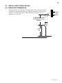
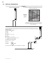
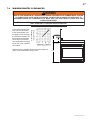
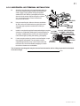
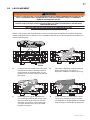
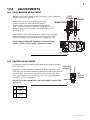
1
INSTALLER: LEAVE THIS MANUAL WITH THE APPLIANCE. CONSUMER: RETAIN THIS MANUAL FOR FUTURE REFERENCE. NEVER LEAVE CHILDREN OR OTHER AT RISK INDIVIDUALS ALONE WITH THE APPLIANCE. 1 INSTALLATION AND OPERATING INSTRUCTIONS CERTIFIED UNDER CANADIAN AND AMERICAN NATIONAL STANDARDS: CSA 2.33, ANSI Z21.88 FOR VENTED GAS FIREPLACES HEATERS. BCDV40-N NATURAL GAS CERTIFIED FOR CANADA AND UNITED STATES USING ANSI/CSA METHODS. SAFETY INFORMATION ! WARNING BCDV40-P If the information in these instructions are not followed exactly, a fire or explosion may result causing property damage, personal injury or loss of life. PROPANE - Do not store or use gasoline or other flammable vapors and liquids in the vicinity of this or any other appliance. - WHAT TO DO IF YOU SMELL GAS: • Do not try to light any appliance. • Do not touch any electrical switch; do not use any phone in your building. • Immediately call your gas supplier from a neighbour’s phone. Follow the gas supplier’s instructions. • If you cannot reach your gas supplier, call the fire department. - Installation and service must be performed by a qualified installer, service agency or the supplier. This appliance may be installed in an aftermarket, permanently located, manufactured home (USA only) or mobile home, where not prohibited by local codes. This appliance is only for use with the type of gas indicated on the rating plate. This appliance is not convertible for use with other gases, unless a certified kit is used. ! WARNING HOT GLASS WILL CAUSE BURNS. DO NOT TOUCH GLASS UNTIL COOLED. NEVER ALLOW CHILDREN TO TOUCH GLASS. Wolf Steel Ltd., 24 Napoleon Rd., Barrie, ON, L4M 0G8 Canada / 103 Miller Drive, Crittenden, Kentucky, USA, 41030 Phone (705)721-1212 • Fax (705)722-6031 • www.continentalfireplaces.com • [email protected] $10.00 1.24B W415-0812 / D / 08.16.12 2 TABLE OF CONTENTS 1.0 2.0 3.0 INSTALLATION OVERVIEW INTRODUCTION 3 4 2.1 2.1.1 2.1.2 2.1.3 2.2 2.3 2.4 5 5 5 5 6 7 7 VENTING 3.1 3.2 3.3 3.3.1 3.4 3.5 3.6 3.7 3.8 3.9 4.0 5.0 6.0 7.0 8.0 9.0 10.0 11.0 12.0 13.0 VENTING LENGTHS AND COMPONENTS TYPICAL VENT INSTALLATIONS SPECIAL VENT INSTALLATIONS PERISCOPE TERMINATION VENT TERMINAL CLEARANCES VENT APPLICATION FLOW CHART DEFINITIONS ELBOW VENT LENGTH VALUES HORIZONTAL TERMINATION VERTICAL TERMINATION 8 8 10 11 11 12 13 13 13 14 16 PENINSULA INSTALLATION 18 4.1 4.2 4.3 4.4 4.5 4.6 18 18 19 20 20 20 VENTING FRAMING COUNTER TOP / BAR INSTALLATION BRICK PANEL INSTALLATION FACING FINISHING OPEN-END INSTALLATION 21 5.1 5.2 5.3 5.4 5.5 21 21 22 22 22 VENTING FRAMING BRICK PANEL INSTALLATION FACING FINISHING SEE-THRU INSTALLATION 23 6.1 6.2 6.3 6.4 6.5 23 23 24 24 24 VENTING FRAMING BRICK PANEL INSTALLATION FACING FINISHING FRAMING 25 7.1 7.2 7.3 7.4 25 25 26 27 MINIMUM CLEARANCE TO COMBUSTIBLES MINIMUM CLEARANCE TO COMBUSTIBLE ENCLOSURES ALCOVE INSTALLATION MINIMUM MANTEL CLEARANCES INSTALLATION 28 8.1 8.1.1 8.1.2 8.2 8.2.1 8.2.2 8.2.3 8.3 8.4 28 29 30 30 31 32 33 33 34 WALL AND CEILING PROTECTION HORIZONTAL INSTALLATION VERTICAL INSTALLATION USING FLEXIBLE VENT COMPONENTS HORIZONTAL AIR TERMINAL INSTALLATION VERTICAL AIR TERMINAL INSTALLATION APPLIANCE VENT CONNECTION GAS INSTALLATION OPTIONAL WALL SWITCH INSTALLATION FINISHING 35 9.1 9.2 9.3 9.4 9.5 9.6 9.7 35 35 36 36 37 38 38 DOOR INSTALLATION END DOOR INSTALLATION HEAT SHIELD STAND-OFF REMOVAL (SEE-THRU INSTALLATION ONLY) LOUVRE INSTALLATION LOG PLACEMENT CHARCOAL EMBERS LOGO PLACEMENT OPTIONAL BLOWER INSTALLATION OPERATION ADJUSTMENTS 39 40 41 12.1 12.2 12.3 12.4 41 41 42 42 PILOT BURNER ADJUSTMENT VENTURI ADJUSTMENT FLAME CHARACTERISTICS RESTRICTING VERTICAL VENTS MAINTENANCE 13.1 14.0 15.0 16.0 17.0 DIMENSIONS PENINSULA OPEN-END SEE-THRU GENERAL INSTRUCTIONS GENERAL INFORMATION RATING PLATE INFORMATION CARE OF GLASS REPLACEMENTS TROUBLESHOOTING WARRANTY SERVICE HISTORY NOTE: Changes, other than editorial, are denoted by a vertical line in the margin. W415-0812 / D / 08.16.12 43 43 44 48 50 51 3 1.0 INSTALLATION OVERVIEW Top, see “COUNTER TOP / BAR INSTALLATION” section. Venting, see “VENTING” section. Bricks, see “BRICK PANEL INSTALLATION” section. . Louvre, see “LOUVRE INSTALLATION” section. Rating plate, see “RATING PLATE INFORMATION” section. Door, see ”DOOR INSTALLATION” section. Door, see ”END DOOR INSTALLATION” section. W415-0812 / D / 08.16.12 4 2.0 INTRODUCTION ! • • • • • • • • • • • • • • • • • • • • • • • • • • • • • • WARNING THIS APPLIANCE IS HOT WHEN OPERATED AND CAN CAUSE SEVERE BURNS IF CONTACTED. ANY CHANGES TO THIS APPLIANCE OR IT’S CONTROLS CAN BE DANGEROUS AND IS PROHIBITED. Do not operate appliance before reading and understanding operating instructions. Failure to operate appliance according to operating instructions could cause fire or injury. Risk of fire or asphyxiation do not operate appliance with fixed glass removed. Do not connect 110 volts to the control valve. Risk of burns. The appliance should be turned off and cooled before servicing. Do not install damaged, incomplete or substitute components. Risk of cuts and abrasions. Wear protective gloves and safety glasses during installation. Sheet metal edges may be sharp. Do not burn wood or other materials in this appliance. Children and adults should be alerted to the hazards of high surface temperature and should stay away to avoid burns or clothing ignition. Young children should be carefully supervised when they are in the same room as the appliance. Toddlers, young children and others may be susceptible to accidental contact burns. A physical barrier is recommended if there are at risk individuals in the house. To restrict access to an appliance or stove, install an adjustable safety gate to keep toddlers, young children and other at risk individuals out of the room and away from hot surfaces. Clothing or other flammable material should not be placed on or near the appliance. Due to high temperatures, the appliance should be located out of traffic and away from furniture and draperies. Ensure you have incorporated adequate safety measure to protect infants/toddlers from touching hot surfaces. Even after the appliance is out, the glass and/or screen will remain hot for an extended period of time. Check with your local hearth specialty dealer for safety screens and hearth guards to protect children from hot surfaces. These screens and guards must be fastened to the floor. Any safety screen or guard removed for servicing must be replaced prior to operating the appliance. The appliance is a vented gas-fired appliance. Do not burn wood or other materials in the appliance. It is imperative that the control compartments, burners and circulating blower and its passageway in the appliance and venting system are kept clean. The appliance and its venting system should be inspected before use and at least annually by a qualified service person. More frequent cleaning may be required due to excessive lint from carpeting, bedding material, etc. The appliance area must be kept clear and free from combustible materials, gasoline and other flammable vapors and liquids. Under no circumstances should this appliance be modified. This appliance must not be connected to a chimney flue pipe serving a separate solid fuel burning appliance. Do not use this appliance if any part has been under water. Immediately call a qualified service technician to inspect the appliance and to replace any part of the control system and any gas control which has been under water. Do not operate the appliance with the glass door removed, cracked or broken. Replacement of the glass should be done by a licensed or qualified service person. Do not strike or slam shut the appliance glass door. When equipped with pressure relief doors, they must be kept closed while the appliance is operating to prevent exhaust fumes containing carbon monoxide, from entering into the home. Temperatures of the exhaust escaping through these openings can also cause the surrounding combustible materials to overheat and catch fire.Only doors / optional fronts certified with the unit are to be installed on the appliance. Only doors / optional fronts certified with the unit are to be installed on the appliance. Keep the packaging material out of reach of children and dispose of the material in a safe manner. As with all plastic bags, these are not toys and should be kept away from children and infants. As with any combustion appliance, we recommend having your appliance regularly inspected and serviced as well as having a Carbon Monoxide Detector installed in the same area to defend you and your family against Carbon Monoxide. Ensure clearances to combustibles are maintained when building a mantel or shelves above the appliance. Elevated temperatures on the wall or in the air above the appliance can cause melting, discolouration or damage to decorations, a T.V. or other electronic components. This appliance uses and requires a fast acting thermocouple. Replace only with a fast acting thermocouple supplied by Wolf Steel Ltd. 3.1C W415-0812 / D / 08.16.12 5 2.1 DIMENSIONS 2.1.1 PENINSULA 22 1/8" 5" DIA. 8" DIA. 38" 32 1/2" GAS INLET 6 /2" 4 1/4" 1 36" 37 5/8" 38 5/8" 2 1/2" 22 1/8" ELECTRICAL INLET 2.1.2 OPEN-END 22 1/8" 5" DIA. 8" DIA. 38" 32 1/2" 6 /2" 4 1/4" 1 36" 37 5/8" 38 5/8" GAS INLET 2 1/2" ELECTRICAL INLET 22 1/8" 25 1/8" 2.1.3 SEE-THRU 22 1/8" 5" DIA. 8" DIA. 38" 32 1/2" 6 /" 4 /" 12 14 36" 40 5/8" GAS INLET 22 1/8" 2 1/2" ELECTRICAL INLET W415-0812 / D / 08.16.12 6 2.2 GENERAL INSTRUCTIONS ! WARNING ALWAYS LIGHT THE PILOT WHETHER FOR THE FIRST TIME OR IF THE GAS SUPPLY HAS RUN OUT, WITH THE GLASS DOOR OPENED OR REMOVED. PROVIDE ADEQUATE CLEARANCE FOR SERVICING AND OPERATING THE APPLIANCE. PROVIDE ADEQUATE VENTILATION. NEVER OBSTRUCT THE FRONT OPENING OF THE APPLIANCE. OBJECTS PLACED IN FRONT OF THE APPLIANCE MUST BE KEPT A MINIMUM OF 48” FROM THE FRONT FACE OF THE APPLIANCE. SURFACES AROUND AND ESPECIALLY ABOVE THE APPLIANCE CAN BECOME HOT. AVOID CONTACT WHEN THE APPLIANCE IS OPERATING. FIRE RISK. EXPLOSION HAZARD. HIGH PRESSURE WILL DAMAGE VALVE. DISCONNECT GAS SUPPLY PIPING BEFORE PRESSURE TESTING GAS LINE AT TEST PRESSURES ABOVE 1/2 PSIG. CLOSE THE MANUAL SHUT-OFF VALVE BEFORE PRESSURE TESTING GAS LINE AT TEST PRESSURES EQUAL TO OR LESS THAN 1/2 PSIG. USE ONLY WOLF STEEL APPROVED OPTIONAL ACCESSORIES AND REPLACEMENT PARTS WITH THIS APPLIANCE. USING NON-LISTED ACCESSORIES (BLOWERS, DOORS, LOUVRES, TRIMS, GAS COMPONENTS, VENTING COMPONENTS, ETC.) COULD RESULT IN A SAFETY HAZARD AND WILL VOID THE WARRANTY AND CERTIFICATION. THIS GAS APPLIANCE SHOULD BE INSTALLED AND SERVICED BY A QUALIFIED INSTALLER to conform with local codes. Installation practices vary from region to region and it is important to know the specifics that apply to your area, for example in Massachusetts State: • This product must be installed by a licensed plumber or gas fitter when installed within the commonwealth of Massachusetts. • The appliance damper must be removed or welded in the open position prior to installation of an appliance insert or gas log. • The appliance off valve must be a “T” handle gas cock. • The flexible connector must not be longer than 36 inches. • A Carbon Monoxide detector is required in all rooms containing gas fired appliances. • The appliance is not approved for installation in a bedroom or bathroom unless the unit is a direct vent sealed combustion product. The installation must conform with local codes or, in absence of local codes, the National Gas and Propane Installation Code CSA B149.1 in Canada, or the National Fuel Gas Code, ANSI Z223.1 / NFPA 54 in the United States. Suitable for mobile home installation if installed in accordance with the current standard CAN/CSA Z240MH Series, for gas equipped mobile homes, in Canada or ANSI Z223.1 and NFPA 54 in the United States. We suggest that our gas hearth products be installed and serviced by professionals who are certified in the U.S. by the National Fireplace Institute® (NFI) as NFI Gas Specialists As long as the required clearance to combustibles is maintained, the most desirable and beneficial location www.nficertified.org for an appliance is in the center of a building, thereby allowing the most efficient use of the heat created. The location of windows, doors and the traffic flow in the room where the appliance is to be located should be considered. If possible, you should choose a location where the vent will pass through the house without cutting a floor or roof joist. If the appliance is installed directly on carpeting, vinyl tile or other combustible material other than wood flooring, the appliance shall be installed on a metal or wood panel extending the full width and depth. Some appliances have optional fans or blowers. If an optional fan or blower is installed, the junction box must be electrically connected and grounded in accordance with local codes, use the current CSA C22.1 Canadian Electrical Code in Canada or the ANSI/NFPA 70 National Electrical code in the United States. 4.1A W415-0812 / D / 08.16.12 7 2.3 GENERAL INFORMATION FOR YOUR SATISFACTION, THIS APPLIANCE HAS BEEN TEST-FIRED TO ASSURE ITS OPERATION AND QUALITY! NG LP Altitude (FT) 0-4,500 0-4500 Max. Input (BTU/HR) 30,000 30,000 Max. Output Steady State (BTU/HR) 20,400 20,400 Min. Inlet Gas Supply Pressure 4.5" Water Column 11" Water Column Max. Inlet Gas Supply Pressure 7" Water Column 13" Water Column 3.5" Water Column 10" Water Column Manifold Pressure (Under Flow Conditions) When the appliance is installed at elevations above 4,500ft, and in the absence of specific recommendations from the local authority having jurisdiction, the certified high altitude input rating shall be reduced at the rate of 4% for each additional 1,000ft. This appliance is approved for bathroom, bedroom and bed-sitting room installations and is suitable for mobile home installation. 66.8% No external electricity (110 volts or 24 volts) is required for the gas system operation. Expansion / contraction noises during heating up and cooling down cycles are normal and are to be expected. BCDV40 If utilizing one of Wolf Steel's trim or surround kits, follow the framing instructions and the finishing instructions, for removal of the top extension. NOTE: The protective wrap on plated parts is best removed when the assembly is at room temperature but this can be improved if the assembly is warmed, using a hair dryer or similar heat source. RATING PLATE INFORMATION CERTIFIED UNDER / HOMOLOGUE SELON LES NORMES: ANSI Z21.50b-2009 CSA 2.22b-2009 VENTED GAS FIREPLACE CE / FOYER AU GAZ AVEC EVACUATION DIRECT VENT GAS FIREPLACE. APPROVED FOR BEDROOM, BATHROOM AND BED-SITTING ROOM INSTALLATION. SUITABLE FOR MOBILE HOME INSTALLATION IF INSTALLED IN ACCORDANCE WITH THE CURRENT STANDARD CAN/CSA Z240MH SERIES GAS EQUIPPED MOBILE HOMES, IN CANADA OR IN THE UNITED STATES THE MANUFACTURED HOME CONSTRUCTION AND SAFETY STANDARD, TITLE 24 CFR, PART 3280. WHEN THIS US STANDARD IS NOT APPLICABLE USE THE STANDARD FOR FIRE SAFETY CRITERIA FOR MANUFACTURED HOME INSTALLATIONS, SITES AND COMMUNITIES, ANSI / NFPA501A. 9700539 (WSL) 4001658 (NAC) BGD40N FOYER A GAZ VENTILE DIRECT. T. HOMO HOMOL HOMOLOGUE POUR INSTALLATION DANS UNE CHAMBRE A COUCHER, USE SALLE LE DE BA BAIN ET UN STUDIO. APPROPRIE POUR INSTALLATION DANS UNE MAISON INSTALLATION CONFROME AUX EXIGENCES DE LA N MOBILE SI SON IN INS NORME CAN/CSA MOBILES EQUIPEES AU GAZ, EN SA A Z240MH SERIE DE MAISONS M VIGUEUR AU CANADA OU AUX ETATS-UNIS DE LA NORME DE SECURITE ET DE ETATS-UN CONSTRUCTION TITRE 24 CFR, SECTION 3280. CTION ON DE MAISONS MANUFACTUREES, MANUFACTU DANS LE D’ETATS-UNIS NE PEUT ETRE APPLIQUEE, SE E CAS OU CETTE NORME D’ETATSREFERER CRITERE DE MESURES DE SECURITE CONTRE RER A LA NORME RME RELATIVE AU CRITE L’INCENDIE LES MAISONS MANUFACTURES, LES CENDIE POUR LES S INSTALLATION DANS D SITES ET LES COMMUNAUTES, ANSI/NFPA 501A. S 4001657 400 (NGZ) 4001659 400165 (WUSA) P L BGD40GN BCDV400N MODEL EL 0-4500FT (0-1370m) 30,000 BTU/h 20,000 BTU/hREDUCED ALTITUDE / ELEVATION INPUT / ALIMENTATION INPUT / ALIMENTATION IMENTATION MENTATION REDUITE MANIFOLD PRESSURE: 3.5" WATER COLUMN LUMN UMN PRESSION AU COLLECTEUR: 3.5" D'UNE COLONNE E D'EAU MINIMUM SUPPLY PRESSURE: 4.5" WATER R COLUMN PRESSION D'ALIMENTATION MINIMALE: 4.5" D'UNE COLONNE ONNE D'EAU MAXIMUM SUPPLY PRESSURE: 7.0" WATER ATER COLUMN COLU PRESSION D'ALIMENTATION MAXIMALE: 7.0" D'UNE E COLONNE D'EA D'EAU NOT FOR USE WITH SOLID FUEL. FOR USE SE E WITH COVERS AND GLASS DOOR CERTIFIED WITH THIS UNIT ONLY. WARNING: DO NOT ADD ANY MATERIAL TO THE APPLIANCE, PPLIANCE, WHICH WILL COME IN CONTACT WITH THE FLAMES, OTHER THAN THAT SUPPLIED PPLIED BY THE MANUFACTURER WIT WITH THE APPLIANCE. MINIMUM CLEARANCE TO COMBUSTIBLE MATERIALS ALS / DEGAGEMENTS MINIMAUX DES MATERIAUX COMBUSTIBLES: OMBUSTIBLES: BUSTIBLES: TOP, FLOOR, SIDES & BACK 0” DESSUS, PLANCHER, COTES ET ARRIERE RECESSED DEPTH (CORNER INSTALLATION 25 1/4” ATION ONLY) PROFONDEUR D’ENCASTRE (INSTALLATION LLATION LATION DU COIN SEULEMENT) VENT / EVENT 1” MANTEL HEIGHT / HAUTEUR DU MANTEAU 5”* *MAXIMUM HORIZONTAL EXTENSION/L’EXTENSION MAXIMALE: 3”. SEE ENSION/L’EXTENSION NSION/L’EXTENSION HORIZONTALE M INSTRUCTION MANUAL FOR R GREATER REATER EXTENSIONS. REFERER AU MANUEL D’INSTRUCTION POUR DES S EXTENSIONS XTENSIONS PLUS GRANDE GRANDES. MINIMUM AND MAXIMUM HORIZONTAL RIZONTAL ZONTAL VENT LENGTHS A ARE 10 INCHES AND 20 FEET RESPECTIVELY. LES LONGUEURS MINIMALE ET MAXIMALE SONT 10 RS S HORIZONTALES MINI MINIM POUCES ET 20 PIEDS RESPECTIVEMENT. EMENT. T. S 2.4 BGD40P D40P BCDV400P BGD40GP 0-4500FT (0(0-1 (0-1370m) BTU/h 30,000 BT BTU BTU/h 20,000 B MANIFOLD NIFOLD PRESSURE: 10 10" WATER COLUMN COLLECTEUR: 10" D'UNE COLONNE D'EAU PRESSION RESSION AU COLLECT COLLEC PRESSURE: 11" WATER COLUMN MINIMUM SUPPLY PR MINIMU D'ALIMENTATION MINIMALE: 11" D'UNE COLONNE D'EAU PRESSION D'ALIME PRES MAXIMUM MAXIMU SUPPLY SUPP PRESSURE: 13" WATER COLUMN PRESSION D'ALIMENTATION MAXIMALE: 13" D'UNE COLONNE D'EAU D'A UN CO COMBUSTIBLE SOLIDE NE DOIT PAS ETRE UTILISE AVE AVEC CET APPAREIL. UTILISER AVEC LES COUVERTURES ET LES PORTES VITREES C HOMOLOGUEES SEULEMENT AVEC CETTE UNITE. AVERTISSEMENT: N’AJOUTEZ PAS A CET APPAREIL AUCUN MATERIAU DEVANT ENTRER EN CONTACT AVEC LES FLAMMES AUTRE QUE CELUI QUI EST FOURNI AVEC CET APPAREIL PAR LE FABRICANT. THE APPLIANCE MUST BE VENTED USING THE APPROPRIATE WOLF STEEL VENT KITS. SEE OWNERS INSTALLATION MANUAL FOR VENTING SPECIFICS. PROPER REINSTALLATION AND RESEALING IS NECESSARY AFTER SERVICING THE VENT-AIR INTAKE SYSTEM. L’APPAREIL DOIT EVACUER SES GAZ EN UTILISANT L’ENSEMBLE D’EVACUATION PROPRE A WOLF STEEL. REFERER AU MANUEL D’INSTALLATION DE PROPRIETAIRE POUR L’EVACUATION PRECISE. IL EST IMPORTANT DE BIEN REINSTALLER L’EVENT APRES AVOIR ASSURE LE MAINTIEN DU SYSTME DE PRISE D’AIR. ELECTRICAL RATING / CLASSIFICATION: 115V, 0.82 AMP, 60HZ OPTIONAL FAN KIT / ENSEMBLE DE VENTILATEUR FACULTATIF: GZ-550KT WOLF STEEL LTD. 24 NAPOLEON ROAD, BARRIE, ON, L4M 0G8 G8 8 CANA CANAD CANADA SERIAL NUMBER/ BGD40 NO. DE SERIE: W385-0656 For rating plate location, see “INSTALLATION OVERVIEW” section. This illustration is for reference only. Refer to the rating plate on the appliance for accurate information. NOTE: The rating plate must remain with the appliance at all times. It must not be removed. W415-0812 / D / 08.16.12 8 3.0 VENTING ! WARNING RISK OF FIRE, MAINTAIN SPECIFIED AIR SPACE CLEARANCES TO VENT PIPE AND APPLIANCE. IF VENTING IS INCLUDED WITH SPACERS THE VENT SYSTEM MUST BE SUPPORTED EVERY 3 FEET FOR BOTH VERTICAL AND HORIZONTAL RUNS. USE SUPPORTS OR EQUIVALENT NON-COMBUSTIBLE STRAPPING TO MAINTAIN THE REQUIRED CLEARANCE FROM COMBUSTIBLES. USE WOLF STEEL LTD. SUPPORT RING ASSEMBLY W010-0370 OR EQUIVALENT NON-COMBUSTIBLE STRAPPING TO MAINTAIN THE MINIMUM CLEARANCE TO COMBUSTIBLES FOR BOTH VERTICAL AND HORIZONTAL RUNS. SPACERS ARE ATTACHED TO THE INNER PIPE AT PREDETERMINED INTERVALS TO MAINTAIN AN EVEN AIR GAP TO THE OUTER PIPE. THIS GAP IS REQUIRED FOR SAFE OPERATION. A SPACER IS REQUIRED AT THE START, MIDDLE AND END OF EACH ELBOW TO ENSURE THIS GAP IS MAINTAINED. THESE SPACERS MUST NOT BE REMOVED. THIS APPLIANCE USES A 5” EXHAUST / 8” AIR INTAKE VENT PIPE SYSTEM. Refer to the section applicable to your installation. For safe and proper operation of the appliance follow the venting instruction exactly. Deviation from the minimum vertical vent length can create difficulty in burner start-up and/or carboning. Under extreme vent configurations, allow several minutes (5-15) for the flame to stabilize after ignition. Provide a means for visually checking the vent connection to the appliance after the appliance is installed. Use a firestop, vent pipe shield or attic insulation shield when penetrating interior walls, floor or ceiling. NOTE: If for any reason the vent air intake system is disassembled; reinstall per the instructions provided for the initial installation. NOTE: This appliance must be installed with a continuous connection of exhaust and air intake vent pipes. Utilizing alternate constructions such as a chimney as part of the vent system is not permitted. 7.2B W415-0812 / D / 08.16.12 9 3.1 VENTING LENGTHS AND COMPONENTS Use only Wolf Steel, Simpson Dura-Vent, Selkirk Direct Temp, American Metal Amerivent or Metal-Fab venting components. Minimum and maximum vent lengths, for both horizontal and vertical installations, and air terminal locations for either system are set out in this manual and must be adhered to. For Simpson DuraVent, Selkirk Direct Temp, American Metal Amerivent and Metal-Fab follow the installation procedure provided with the venting components. A starter adaptor must be used with the following vent systems and may be purchased from the corresponding supplier: PART 5”/8” SUPPLIER WEBSITE Duravent W175-0170 Wolf Steel www.duravent.com Amerivent 5DSC-N2 American Metal www.americanmetalproducts.com Direct Temp 5DT-AA Selkirk www.selkirkcorp.com SuperSeal 5DDA Metal-Fab www.mtlfab.com For Simpson Dura-Vent, Selkirk Direct Temp, American Metal Amerivent and Metal-Fab follow the installation procedure found on the website for your venting supplier. For vent systems that provide seals on the inner exhaust flue, only the outer air intake joints must be sealed using a red high temperature silicone (RTV). This same sealant may be used on both the inner exhaust and outer intake vent pipe joints of all other approved vent systems except for the exhaust vent pipe connection to the appliance flue collar which must be sealed using the black high temperature sealant Mill Pac. When using Wolf Steel venting components, use only approved Wolf Steel rigid / flexible components with the following termination kits: wall terminal kit GD422-1, GD422R-1, or 1/12 to 7/12 pitch roof terminal kit GD410, 8/12 to 12/12 roof terminal kit GD411, flat roof terminal kit GD412 or periscope kit GD401 (for wall penetration below grade). With flexible venting, in conjunction with the various terminations, use either the 5 foot vent kit GD420 or the 10 foot vent kit GD430. For optimum flame appearance and appliance performance, keep the vent length and number of elbows to a minimum. The air terminal must remain unobstructed at all times. Examine the air terminal at least once a year to verify that it is unobstructed and undamaged. Rigid and flexible venting systems must not be combined. Different venting manufacturer components must not be combined. These vent kits allow for either horizontal or vertical venting of the appliance. The maximum allowable horizontal run is 20 feet. The maximum allowable vertical vent length is 40 feet. The maximum number of vent connections is two horizontally or three vertically (excluding the appliance and the air terminal connections) when using flexible venting. Horizontal runs may have a 0” rise per foot however for optimum performance it is recommended that all horizontal runs have a minimum 1/4” rise per foot using flexible venting. For safe and proper operation of the appliance, follow the venting instructions exactly. A terminal shall not terminate directly above a sidewalk or paved driveway which is located between two single family dwellings and serves both dwellings. Local codes or regulations may require different clearances. Do not allow the inside liner to bunch up on horizontal or vertical runs and elbows. Keep it pulled tight. A 1¼” air gap all around between the inner liner and outer liner is required for safe operation. 8.3 W415-0812 / D / 08.16.12 10 3.2 TYPICAL VENT INSTALLATIONS 16" MIN 40 FT MAX 34" MIN 24" MAX 38" MIN PLUS RISE* When venting, the horizontal run must be kept to a maximum of 20 feet. If a 20 foot horizontal run is required, the appliance must have a minimum vertical rise immediately off the appliance of 57". 37 3/4" When terminating vertically, the vertical rise is a minimum 34" and a maximum 40 feet above the appliance. When installing with no vertical rise, ensure that the vent pipe does not slope downward. * See "VENTING" section. W415-0812 / D / 08.16.12 11 3.3 SPECIAL VENT INSTALLATIONS 3.3.1 PERISCOPE TERMINATION Use the periscope kit to locate the air termination above grade. The periscope must be installed so that when final grading is completed, the bottom air slot is located a minimum of 12” above grade. The maximum allowable vent length is 10’ for a fireplace and 8’ for a stove. 12" MIN TO GRADE 24" MIN REGARDLESS OF HORIZONTAL VENT LENGTH 37 3/4" MIN 9.5A W415-0812 / D / 08.16.12 12 3.4 VENT TERMINAL CLEARANCES COVERED BALCONY APPLICATIONS ††* Q R INSTALLATIONS CANADA U.S.A. S G Q MIN = 3 feet R MAX = 2 x Q ACTUAL R MAX feet P A 12” 12” Clearance above grade, veranda porch, deck or balcony. B 12” Δ 9” Δ Clearance to windows or doors that open. C 12” * 12” * Clearance to permanently closed windows. D 18” ** 18” ** Vertical clearance to ventilated soffits located above the terminal within a horizontal distance of 2’ from the center line of the terminal. E 12” ** 12” ** Clearance to unventilated soffit. 0” 0” 0” *** 0” *** Clearance to an inside non-combustible corner wall or protruding non-combustible obstructions (chimney, etc.). 2” *** 2” *** Clearance to an inside combustible corner wall or protruding combustible obstructions (vent chase, etc.). H 3’ 3’ **** Clearance to each side of the center line extended above the meter / regulator assembly to a maximum vertical distance of 15’. I 3’ 3’ **** Clearance to a service regulator vent outlet. J 12” 9” K 6’ 3’ † F G Clearance to an outside corner wall. Clearance to a non-mechanical air supply inlet to the building or a combustion air inlet to any other appliance. Clearance to a mechanical air supply inlet. L 7’ ‡ 7’ **** M 12” †† 12” **** N 16” 16” Clearance above the roof. O 2’ †* 2’ †* Clearance from an adjacent wall including neighbouring buildings. P 8’ 8’ Roof must be non-combustible without openings. Q 3’ 3’ See chart for wider wall dimensions. R 6’ 6’ See chart for deeper wall dimensions. The terminal shall not be installed on any wall that has an opening between the terminal and the open side of the structure. 12” 12” S Δ Clearance above a paved sidewalk or paved driveway located on public property. Clearance under a veranda, porch or deck. Clearance under a covered balcony The terminal shall not be located less than 6 feet under a window that opens on a horizontal plane in a structure with three walls and a roof. * Recommended to prevent condensation on windows and thermal breakage ** It is recommended to use a heat shield and to maximize the distance to vinyl clad soffits. *** The periscope requires a minimum 18 inches clearance from an inside corner. **** This is a recommended distance. For additional requirements check local codes. † 3 feet above if within 10 feet horizontally. ‡ A vent shall not terminate where it may cause hazardous frost or ice accumulations on adjacent property surfaces. †† Permitted only if the veranda, porch, or deck is fully open on a minimum of two sides beneath the floor. †* Recommended to prevent recirculation of exhaust products. For additional requirements check local codes. ††* Permitted only if the balcony is fully open on a minimum of one side. NOTE: Clearances are in accordance with local installation codes and the requirements of the gas supplier. 12.1C W415-0812 / D / 08.16.12 13 3.5 VENT APPLICATION FLOW CHART TOP EXIT Horizontal Termination Vertical Termination Vertical rise is equal to or greater than the horizontal run Vertical rise is less than horizontal run Vertical rise is equal to or greater than the horizontal run Vertical rise is less than horizontal run Horizontal run + vertical rise to maximum of 40 feet Horizontal run + vertical rise to maximum of 24.75 feet Horizontal run + vertical rise to maximum of 40 feet Horizontal run + vertical rise to maximum of 40 feet 4.2 times the vertical rise equal to or greater than the horizontal run 3 times the vertical rise equal to or greater than the horizontal run 13.1 3.6 DEFINITIONS For the following symbols used in the venting calculations and examples are: > - greater than > - equal to or greater than < - less than < - equal to or less than HT - total of both horizontal vent lengths (Hr) and offsets (Ho) in feet HR - combined horizontal vent lengths in feet HO - offset factor: .03 (total degrees of offset - 135°*) in feet VT - combined vertical vent lengths in feet 14.2 3.7 ELBOW VENT LENGTH VALUES 1° 15° 30° 45°* 90°* FEET 0.03 0.45 0.9 1.35 2.7 INCHES 0.5 6.0 11.0 16.0 32.0 * The first 45° and 90°offset has a zero value and is shown in the formula as -45° and - 90° respectively or -135° when combined. 15.2 W415-0812 / D / 08.16.12 14 3.8 HORIZONTAL TERMINATION (HT) < (VT) See graph to determine the required vertical rise VT for the required horizontal run HT. Simple venting configuration (only one 45° and 90° elbow) 39 REQUIRED VERTICAL RISE IN FEET VT 40 30 20 10 0 2.5 5 7.5 10 12.5 15 17.5 20 HORIZONTAL VENT RUN PLUS OFFSET IN FEET HT The shaded area within the lines represents acceptable values for HT and VT For vent configurations requiring more than one 45° elbow and 90° elbow, the following formulas apply: Formula 1: HT < VT Formula 2: HT + VT < 40 feet Example: V1 = 8 FT VT = V1 = 8 FT H1 = 2.5 FT H2 = 2 FT HR = H1 + H2 = 2.5 + 2 = 4.5 FT HO = .03 (one 45° elbow + two 90° elbows - 135°) = .03 (225 - 135°) = 2.7 FT HT = HR + HO = 4.5 + 2.7 = 7.2 FT 45° H1 HT + VT = 7.2 + 8 = 15.2 FT 90° V1 90° Formula 1: HT < VT 7.2 < 8 Formula 2: HT + VT < 40 FT 15.2 < 40 Since both formulas are met, this vent configuration is acceptable. 16.5 W415-0812 / D / 08.16.12 H2 15 (HT) > (VT) Simple venting configuration (only one 45° and 90° elbow) See graph to determine the required vertical rise VT for the required horizontal run HT. 147” REQUIRED VERTICAL RISE IN INCHES VT 150 100 57” 50 0 5 15 10 20 12.5’ HORIZONTAL VENT RUN PLUS OFFSET IN FEET HT The shaded area within the lines represents acceptable values for HT and VT For vent configurations requiring more than one 45° elbow and 90° elbow, the following formulas apply: Formula 1: HT < 4.2 VT Formula 2: HT + VT < 24.75 feet Example: V1 = 4 FT V2 = 1.5 FT VT = V1 + V2= 4 FT + 1.5 FT = 5.5 FT H1 = 2 FT 90° H2 = 1 FT H1 H3 = 1 FT H4 = 1.5 FT V1 HR = H1 + H2 + H3 + H4 = 2 + 1 + 1 + 1.5 = 5.5 FT HO = .03 (one 45° elbow + four 90° elbows - 135°) = .03 (405 - 135°) = 8.1 FT HT = HR + HO = 5.5 + 8.1 = 13.6 FT 45° HT + VT = 13.6 + 5.5 = 19.1 FT 90° 90° H3 V2 H2 H4 90° Formula 1: HT < 4.2 VT 4.2 VT = 4.2 x 5.5 FT = 23.1 FT 13.6 < 23.1 Formula 2: HT + VT < 24.75 FT 19.1 < 24.75 Since both formulas are met, this vent configuration is acceptable. 16.5_2 W415-0812 / D / 08.16.12 16 3.9 VERTICAL TERMINATION (HT) < (VT) Simple venting configurations. See graph to determine the required vertical rise VT for the required horizontal run HT. 40 30 REQUIRED VERTICAL RISE IN FEET VT 20 10 3 0 5 10 15 20 HORIZONTAL VENT RUN PLUS OFFSET IN FEET HT The shaded area within the lines represents acceptable values for HT and VT For vent configurations requiring more than one 45° and one 90° elbow, the following formulas apply: Formula 1: HT < VT Formula 2: HT + VT < 40 feet Example: V1 = 5 FT V2 = 10 FT VT = V1 + V2 = 5 + 10 = 15 FT H1 = 3 FT H2 = 2.5 FT HR = H1 + H2 = 3 + 2.5 = 5.5 FT HO = .03 (one 45° + three 90° elbows - 135°) = .03 (45 + 270 - 135°) = 5.4 FT HT = HR + HO = 5.5 + 5.4 = 10.9 FT HT + VT = 10.9 + 15 = 25.9 FT HT < VT 10.9 < 15 Formula 2: HT + VT < 40 FT 25.9 < 40 Since both formulas are met, this vent configuration is acceptable. Formula 1: V2 90° H2 V1 45° H1 90° 18.3 W415-0812 / D / 08.16.12 90° 17 (HT) > (VT) Simple venting configurations. See graph to determine the required vertical rise VT for the required horizontal run HT. 19 REQUIRED VERTICAL RISE IN FEET VT 20 10 3 0 5 10 15 25 20 30 HORIZONTAL VENT RUN PLUS OFFSET IN FEET HT The shaded area within the lines represents acceptable values for HT and VT For vent configurations requiring more than one 45° and one 90° elbow, the following formulas apply: Formula 1: HT < 3VT Formula 2: HT + VT < 40 feet 45° Example: V1 = 1 FT V2 = 1.5 FT VT = V1 + V2 = 1 + 1.5 = 2.5 FT H1 = 6 FT H2 = 2 FT HR = H1 + H2 = 6 + 2 = 8 FT HO = .03 (one 45° + three 90° elbows - 135°) = .03 (45 + 270 - 135°) = 5.4 FT HT = HR + HO = 8 + 5.4 = 13.4 FT HT + VT = 13.4 + 2.5 = 15.9 FT V2 90° H1 V1 H2 90° 90° Formula 1: HT < 3VT 3VT = 3 x 2.5 = 7.5 FT 13.4 > 7.5 Since this formula is not met, this vent configuration is unacceptable. Formula 2: HT + VT < 40 FT 15.9 < 40 Since only formula 2 is met, this vent configuration in unacceptable and a new fireplace location or vent configuration will need to be established to satisfy both formulas. Example: V1 = 1.5 FT V2 = 8 FT VT = V1 + V2 = 1.5 + 8 = 9.5 FT H1 = 1 FT H2 = 1 FT H3 = 10.75 FT HR = H1 + H2 + H3 = 1 + 1 + 10.75 = 12.75 FT HO = .03 (three 90° elbows + two 45° elbows - 135°) = .03 (270 + 90 - 135°) = 6.75 FT HT = HR + HO = 12.75 + 6.75 = 19.5 FT HT + VT = 19.5 + 9.5 = 29 FT V2 90° H2 45° H1 V1 H3 90° 45° 90° Formula 1: HT < 3VT 3VT = 3 x 9.5 = 28.5 FT 19.5 < 28.5 Formula 2: HT + VT < 40 FT 29 < 40 Since both formulas are met, this vent configuration is acceptable. 18.3_2A W415-0812 / D / 08.16.12 18 4.0 PENINSULA INSTALLATION 4.1 VENTING Refer to "VENTING" section. All venting must have a minimum clearance of 2" to combustible material on the top and 1" to the sides and bottom. 4.2 FRAMING ! WARNING RISK OF FIRE! IN ORDER TO AVOID THE POSSIBILITY OF EXPOSED INSULATION OR VAPOUR BARRIER COMING IN CONTACT WITH THE APPLIANCE BODY, IT IS RECOMMENDED THAT THE WALLS OF THE APPLIANCE ENCLOSURE BE “FINISHED” (IE: DRYWALL / SHEETROCK), AS YOU WOULD FINISH ANY OTHER OUTSIDE WALL OF A HOME. THIS WILL ENSURE THAT CLEARANCE TO COMBUSTIBLES IS MAINTAINED WITHIN THE CAVITY. DO NOT NOTCH THE FRAMING AROUND THE APPLIANCE STAND-OFFS. FAILURE TO MAINTAIN AIR SPACE CLEARANCE MAY CAUSE OVER HEATING AND FIRE. PREVENT CONTACT WITH SAGGING OR LOOSE INSULATION OR FRAMING AND OTHER COMBUSTIBLE MATERIALS. BLOCK OPENING INTO THE CHASE TO PREVENT ENTRY OF BLOWN-IN INSULATION. MAKE SURE INSULATION AND OTHER MATERIALS ARE SECURED. WHEN CONSTRUCTING THE ENCLOSURE ALLOW FOR FINISHING MATERIAL THICKNESS TO MAINTAIN CLEARANCES. FRAMING OR FINISHING MATERIAL CLOSER THAN THE MINIMUMS LISTED MUST BE CONSTRUCTED ENTIRELY OF NON-COMBUSTIBLE MATERIALS. MATERIALS CONSISTING ENTIRELY OF STEEL, IRON, BRICK, TILE, CONCRETE, SLATE, GLASS OR PLASTERS, OR ANY COMBINATION THEREOF ARE SUITABLE. MATERIALS THAT ARE REPORTED AS PASSING ASTM E 136, STANDARD TEST METHOD FOR BEHAVIOUR OF MATERIALS IN A VERTICAL TUBE FURNACE AT 750°C AND UL763 SHALL BE CONSIDERED NON-COMBUSTIBLE MATERIALS. MINIMUM CLEARANCE TO COMBUSTIBLES MUST BE MAINTAINED OR A SERIOUS FIRE HAZARD COULD RESULT. THE APPLIANCE REQUIRES A MINIMUM ENCLOSURE HEIGHT. MEASURE FROM THE APPLIANCE BASE. IF STEEL STUD FRAMING KITS WITH CEMENT BOARD ARE PROVIDED, THEY MUST BE INSTALLED. 71.1 It is best to frame your appliance after it is positioned and the vent system is installed. Use 2x4s and frame to local building codes. A To install the appliance face flush with the finished wall, position the framework to accommodate the thickness of the finished wall. A = 22 1/8" minus finishing material thickness each side. 38 1/4” THE UNIT IS NOT LOAD BEARING 2 1/2” 6 1/8” 38 5/8” NOTE: If installing an alcove see "FRAMING" section. W415-0812 / D / 08.16.12 22 1/8” 19 Care should be taken to maintain sufficient clearance for the vent installation. A horizontal vent installation requires a minimum height of 45" using flexible vent pipe, to the underside of the enclosure top including the 2" clearance to combustibles 2" CLEARANCE TO COMBUSTIBLES 20" MINIMUM INSIDE DIMENSION 7" 7" 45" MINIMUM 4.3 COUNTER TOP / BAR INSTALLATION When finishing the appliance, combustible material may rest directly on the top extension. NOTE: Maximum weight tolerance is 400 lbs, provided that it is evenly distributed across the top extensions of the appliance. In order to achieve a counter top or bar type appearance with the minimum height allowed, framing must be non-combustible and may be done with metal studding attached to the top extension sides or the upper frame of the appliance. * The top extension may be removed if non-combustible framing is faced with a non-combustible material placed flush with the front face of the appliance and extending from the top of the appliance. (Example: cement board - not supplied). Combustible counter / bar tops must maintain a minimum of 38" from the base of the appliance to the underside of the top. NOTE: Wolf Steel trim and/or surround kits will not totally cover the top extension of the appliance. In order to obtain a smooth transition from the trim / surround to the wall, it is recommended that the top extension be removed and the appliance be installed following the above procedure. W415-0812 / D / 08.16.12 20 4.4 BRICK PANEL INSTALLATION Install the base panels as illustrated. The side panel sits under the bracket tab. Holding the side panel in position, bend down the tab to secure. STEP 1 STEP 2 STEP 3 STEP 4 RETAINER STEP 5 DETAIL 5 4.5 FACING Combustible materials may be installed flush with the front of the appliance but must not cover any of the black face-areas of the appliance. Non-combustible material (brick, stone or ceramic tile) may protrude in these areas. DRYWALL DRYWALL It is not necessary to install a hearth extension with this appliance. When roughing in the appliance, raise the appliance to accommodate for the thickness of the finished floor materials, (tile, carpeting, hard wood) which if not planned for will interfere with the opening of the lower access door and the installation of many decorative flashing accessories. Objects placed in front of the appliance should be kept a minimum of 48" away from the glass front face. 4.6 5" MIN FINISHING Refer to "FINISHING" section for complete instructions regarding mantel requirements and installations, log placement, glass door and upper and lower louvre attachments. W415-0812 / D / 08.16.12 21 5.0 OPEN-END INSTALLATION 5.1 VENTING Refer to "VENTING" section. All venting must have a minimum clearance of 2" to combustible material on the top and 1" to the sides and bottom. 5.2 FRAMING ! WARNING RISK OF FIRE! IN ORDER TO AVOID THE POSSIBILITY OF EXPOSED INSULATION OR VAPOUR BARRIER COMING IN CONTACT WITH THE APPLIANCE BODY, IT IS RECOMMENDED THAT THE WALLS OF THE APPLIANCE ENCLOSURE BE “FINISHED” (IE: DRYWALL / SHEETROCK), AS YOU WOULD FINISH ANY OTHER OUTSIDE WALL OF A HOME. THIS WILL ENSURE THAT CLEARANCE TO COMBUSTIBLES IS MAINTAINED WITHIN THE CAVITY. DO NOT NOTCH THE FRAMING AROUND THE APPLIANCE STAND-OFFS. FAILURE TO MAINTAIN AIR SPACE CLEARANCE MAY CAUSE OVER HEATING AND FIRE. PREVENT CONTACT WITH SAGGING OR LOOSE INSULATION OR FRAMING AND OTHER COMBUSTIBLE MATERIALS. BLOCK OPENING INTO THE CHASE TO PREVENT ENTRY OF BLOWN-IN INSULATION. MAKE SURE INSULATION AND OTHER MATERIALS ARE SECURED. WHEN CONSTRUCTING THE ENCLOSURE ALLOW FOR FINISHING MATERIAL THICKNESS TO MAINTAIN CLEARANCES. FRAMING OR FINISHING MATERIAL CLOSER THAN THE MINIMUMS LISTED MUST BE CONSTRUCTED ENTIRELY OF NON-COMBUSTIBLE MATERIALS. MATERIALS CONSISTING ENTIRELY OF STEEL, IRON, BRICK, TILE, CONCRETE, SLATE, GLASS OR PLASTERS, OR ANY COMBINATION THEREOF ARE SUITABLE. MATERIALS THAT ARE REPORTED AS PASSING ASTM E 136, STANDARD TEST METHOD FOR BEHAVIOUR OF MATERIALS IN A VERTICAL TUBE FURNACE AT 750°C AND UL763 SHALL BE CONSIDERED NON-COMBUSTIBLE MATERIALS. MINIMUM CLEARANCE TO COMBUSTIBLES MUST BE MAINTAINED OR A SERIOUS FIRE HAZARD COULD RESULT. THE APPLIANCE REQUIRES A MINIMUM ENCLOSURE HEIGHT. MEASURE FROM THE APPLIANCE BASE. IF STEEL STUD FRAMING KITS WITH CEMENT BOARD ARE PROVIDED, THEY MUST BE INSTALLED. 71.1 It is best to frame your appliance after it is positioned and the vent system is installed. Use 2x4s and frame to local building codes. NOTE: The one side stud must be steel. LEFT CORNER Appliance ILLUSTRATED To install the appliance face flush with the finished wall, position the framework to accommodate the thickness of the finished wall. 38 1/4” STEEL STUD 2 1/2” 6 1/2” A 38 5/8” THE UNIT IS NOT LOAD BEARING A = 25 1/8" minus finishing material thickness each side. NOTE: If installing an alcove see "FRAMING" section. W415-0812 / D / 08.16.12 22 5.3 BRICK PANEL INSTALLATION Install the base panels as illustrated in steps 1-4, see "PENINSULA INSTALLATION PROCEDURE" section. The side panel sits under the bracket tab. Holding the side panel in position, bend down the tab to secure. DETAIL 6. STEP 5 RETAINER DETAIL 6 5.4 STEP 6 FACING Combustible materials may be installed flush with the front of the appliance but must not cover any of the black face-areas of the appliance. Non-combustible material (brick, stone or ceramic tile) may protrude in these areas. It is not necessary to install a hearth extension with this appliance. When roughing in the appliance, raise the appliance to accommodate for the thickness of the finished floor materials, i.e. tile, carpeting, hard wood, which if not planned for will interfere with the opening of the lower access door and the installation of many decorative flashing accessories. Objects placed in front of the appliance should be kept a minimum of 48" away from the glass front faces. 5.5 FINISHING ! WARNING FINISHING MUST BE DONE USING A NON-COMBUSTIBLE MATERIAL PLACED FLUSH WITH THE FRONT FACE OF THE APPLIANCE AND EXTENDING FROM THE TOP OF THE APPLIANCE SUCH AS CEMENT BOARD, CERAMIC TILE, MARBLE, ETC. WHEN FINISHING TO THE APPLIANCE. DO NOT USE WOOD OR DRYWALL. ANY FIRE RATED DRYWALL IS NOT ACCEPTABLE. Refer to "FINISHING" section for complete instructions regarding mantel requirements and installations, log placement, glass door and upper and lower louvre attachments. A minimum of 3" of cement board or non-combustible equivalent must be installed against the side edge of the appliance. DRYWALL DRYWALL NONCOMBUSTIBLE 3" W415-0812 / D / 08.16.12 5" MIN 23 6.0 SEE-THRU INSTALLATION 6.1 VENTING Refer to "VENTING" section. All venting must have a minimum clearance of 2" to combustible material on the top and 1" to the sides and bottom. 6.2 FRAMING ! WARNING RISK OF FIRE! IN ORDER TO AVOID THE POSSIBILITY OF EXPOSED INSULATION OR VAPOUR BARRIER COMING IN CONTACT WITH THE APPLIANCE BODY, IT IS RECOMMENDED THAT THE WALLS OF THE APPLIANCE ENCLOSURE BE “FINISHED” (IE: DRYWALL / SHEETROCK), AS YOU WOULD FINISH ANY OTHER OUTSIDE WALL OF A HOME. THIS WILL ENSURE THAT CLEARANCE TO COMBUSTIBLES IS MAINTAINED WITHIN THE CAVITY. DO NOT NOTCH THE FRAMING AROUND THE APPLIANCE STAND-OFFS. FAILURE TO MAINTAIN AIR SPACE CLEARANCE MAY CAUSE OVER HEATING AND FIRE. PREVENT CONTACT WITH SAGGING OR LOOSE INSULATION OR FRAMING AND OTHER COMBUSTIBLE MATERIALS. BLOCK OPENING INTO THE CHASE TO PREVENT ENTRY OF BLOWN-IN INSULATION. MAKE SURE INSULATION AND OTHER MATERIALS ARE SECURED. WHEN CONSTRUCTING THE ENCLOSURE ALLOW FOR FINISHING MATERIAL THICKNESS TO MAINTAIN CLEARANCES. FRAMING OR FINISHING MATERIAL CLOSER THAN THE MINIMUMS LISTED MUST BE CONSTRUCTED ENTIRELY OF NON-COMBUSTIBLE MATERIALS. MATERIALS CONSISTING ENTIRELY OF STEEL, IRON, BRICK, TILE, CONCRETE, SLATE, GLASS OR PLASTERS, OR ANY COMBINATION THEREOF ARE SUITABLE. MATERIALS THAT ARE REPORTED AS PASSING ASTM E 136, STANDARD TEST METHOD FOR BEHAVIOUR OF MATERIALS IN A VERTICAL TUBE FURNACE AT 750°C AND UL763 SHALL BE CONSIDERED NON-COMBUSTIBLE MATERIALS. MINIMUM CLEARANCE TO COMBUSTIBLES MUST BE MAINTAINED OR A SERIOUS FIRE HAZARD COULD RESULT. THE APPLIANCE REQUIRES A MINIMUM ENCLOSURE HEIGHT. MEASURE FROM THE APPLIANCE BASE. IF STEEL STUD FRAMING KITS WITH CEMENT BOARD ARE PROVIDED, THEY MUST BE INSTALLED. 71.1 It is best to frame your appliance after it is positioned and the vent system is installed. Use 2x4s and frame to local building codes. See "BAR TYPE / COUNTER TOP INSTALLATION" section. 38 1/4” A 2 1/2” 6 1/2” 41 1/8” A = 22 1/8" minus finishing material thickness, each side. NOTE: If installing an alcove see "FRAMING" section. W415-0812 / D / 08.16.12 24 6.3 BRICK PANEL INSTALLATION Install the base panels as illustrated in steps 1-4, see "PENINSULA INSTALLATION PROCEDURE" section. Both side panels sit under the bracket tab. Holding the side panel in position, bend down the tab to secure. DETAIL 6. RETAINER STEP 5 DETAIL 5 & 6 RETAINER STEP 6 6.4 FACING Combustible materials may be installed flush with the front of the appliance but must not cover any of the black face-areas of the appliance. Non-combustible material (brick, stone or ceramic tile) may protrude in these areas. It is not necessary to install a hearth extension with this appliance. When roughing in the appliance, raise the appliance to accommodate for the thickness of the finished floor materials, i.e. tile, carpeting, hard wood, which if not planned for will interfere with the opening of the lower access door and the installation of many decorative flashing accessories. Objects placed in front of the appliance should be kept a minimum of 48" away from the glass front faces. 6.5 FINISHING Refer to "FINISHING" section for complete instructions regarding mantel requirements and installations, log placement, glass door and upper and lower louvre attachments. DRYWALL DRYWALL 5" MIN W415-0812 / D / 08.16.12 25 7.0 FRAMING 7.1 MINIMUM CLEARANCE TO COMBUSTIBLES Minimum clearance to combustible construction from appliance and vent surfaces: Sides, back, bottom, and top 0" Vent pipe side, bottom and top* 2" Recessed depth (corner installation) 25¼" Ceiling 54" from bottom of appliance. Enclosure 38" from bottom of appliance. * HORIZONTAL VENT SECTIONS: A minimum clearance of 1" at the bottom and sides and 2" at the top of the vent pipe on all horizontal runs to combustibles is required. Use firestop spacer W010-2116 (supplied). * VERTICAL VENT SECTIONS: A minimum clearance of 1" all around the vent pipe on all vertical runs to combustibles is required except for clearances in appliance enclosures. Use firestop spacer W500-0367 (not supplied). Horizontal Vent Off Appliance Vertical Vent Off Appliance A = 43" using flexible vent components. B = 45" using flexible vent components. 7.2 MINIMUM CLEARANCE TO COMBUSTIBLE ENCLOSURES W415-0812 / D / 08.16.12 26 7.3 ALCOVE INSTALLATION RECESS OR ALCOVE AREA ENCLOSURE AREA APPLIANCE NOTE: Recesses or alcoves above the appliance can be made as deep as desired provided the minimum clearances to combustibles are maintained. Non-combustible material can be used, provided the minimum clearances to combustible materials are applied. The minimum enclosure volume must be increased by no less than the volume of the recess. This adjustment can be made by increasing any or all of the height, width and depth of the enclosure. 71.2 W415-0812 / D / 08.16.12 27 7.4 MINIMUM MANTEL CLEARANCES ! WARNING RISK OF FIRE, MAINTAIN ALL SPECIFIED AIR SPACE CLEARANCES TO COMBUSTIBLES. FAILURE TO COMPLY WITH THESE INSTRUCTIONS MAY CAUSE A FIRE OR CAUSE THE APPLIANCE TO OVERHEAT. ENSURE ALL CLEARANCES (I.E. BACK, SIDE, TOP, VENT, MANTEL, FRONT, ETC.) ARE CLEARLY MAINTAINED. WHEN USING PAINT OR LACQUER TO FINISH THE MANTEL, THE PAINT OR LACQUER MUST BE HEAT RESISTANT TO PREVENT DISCOLOURATION. 73.1 Combustible mantel clearance can vary according to the mantel depth. Use the graph to help evaluate the clearance needed. The three-sided top extension piece may be removed if non-combustible framing is faced with a non-combustible material. Dashed lines are suitable mantel sizes and clearances when a non-combustible facing is used. 11” MANTEL 7” MANTEL 11” 7” TOP OF APPLIANCE 32 1/2” W415-0812 / D / 08.16.12 28 8.0 INSTALLATION ! WARNING FOR SAFE AND PROPER OPERATION OF THE APPLIANCE, FOLLOW THE VENTING INSTRUCTIONS EXACTLY. ALL INNER EXHAUST AND OUTER INTAKE VENT PIPE JOINTS MAY BE SEALED USING EITHER RED RTV HIGH TEMP SILICONE SEALANT W573-0002 (NOT SUPPLIED) OR BLACK HIGH TEMP MILL PAC W573-0007 (NOT SUPPLIED) WITH THE EXCEPTION OF THE APPLIANCE EXHAUST FLUE COLLAR WHICH MUST BE SEALED USING MILL PAC. IF USING PIPE CLAMPS TO CONNECT VENT COMPONENTS, 3 SCREWS MUST ALSO BE USED TO ENSURE THE CONNECTION CANNOT SLIP OFF. DO NOT CLAMP THE FLEXIBLE VENT PIPE. RISK OF FIRE, EXPLOSION OR ASPHYXIATION. IMPROPER SUPPORT OF THE ENTIRE VENTING SYSTEM MAY ALLOW VENT TO SAG AND SEPARATE. USE VENT RUN SUPPORTS AND CONNECT VENT SECTIONS PER INSTALLATION INSTRUCTIONS. RISK OF FIRE, DO NOT ALLOW LOOSE MATERIALS OR INSULATION TO TOUCH THE VENT PIPE. REMOVE INSULATION TO ALLOW FOR THE INSTALLATION OF THE ATTIC SHIELD AND TO MAINTAIN CLEARANCES TO COMBUSTIBLES. 68.2A 8.1 WALL AND CEILING PROTECTION ! WARNING DO NOT FILL THE SPACE BETWEEN THE VENT PIPE AND ENCLOSURE WITH ANY TYPE OF MATERIAL. DO NOT PACK INSULATION OR COMBUSTIBLES BETWEEN CEILING FIRESTOPS. ALWAYS MAINTAIN SPECIFIED CLEARANCES AROUND VENTING AND FIRESTOP SYSTEMS. INSTALL WALL SHIELDS AND FIRESTOPS AS SPECIFIED. FAILURE TO KEEP INSULATION OR OTHER MATERIALS AWAY FROM VENT PIPE MAY CAUSE FIRE. 70.1 For clearance to combustible materials from the vent pipe, see "MINIMUM CLEARANCE TO COMBUSTIBLES" section. W415-0812 / D / 08.16.12 29 8.1.1 HORIZONTAL INSTALLATION ! WARNING THE FIRESTOP ASSEMBLY MUST BE INSTALLED WITH THE VENT SHIELD TO THE TOP. TERMINALS MUST NOT BE RECESSED INTO A WALL OR SIDING MORE THAN THE DEPTH OF THE RETURN FLANGE OF THE MOUNTING PLATE. This application occurs when venting through an exterior wall. Having determined the correct height for the air terminal location, cut and frame a hole in the exterior wall as illustrated to accommodate the firestop assembly. The length of the vent shield may be cut shorter for combustible walls that are less than 8 1/2” thick but the vent shield must extend the full depth of the combustible wall. CAULKING FIRESTOP SPACER A. Apply a bead of caulking (not supplied) all around and place the firestop top, so that the vent shield covers the top of the vent within the opening. DETERMINE THE CORRECT HEIGHT CAULKING FINISHING MATERIAL B. Place the firestop bottom against the firestop top and secure the two together. Adjust the assembly to ensure it is tight to the vent. Secure firestop to wall. This restricts cold air from being drawn into the room or around the appliance. Ensure that both spacer and shield maintain the required clearance to combustibles. VENT Once the vent pipe is installed in its final position, SHIELD apply sealant W573-0002 (not supplied) between the vent pipe and the firestop spacer as illustrated. FIRESTOP TOP FIRESTOP BOTTOM 20.3 W415-0812 / D / 08.16.12 30 8.1.2 VERTICAL INSTALLATION This application occurs when venting through a roof. Installation kits for various roof pitches are available from your authorized dealer / distributor. See accessories to order specific kits required. A. Determine the air terminal location, cut and frame a square opening as illustrated in the ceiling and the roof to provide the minimum 1“ clearance between the vent pipe and any combustible material. Try to center the vent pipe location midway between two joists to prevent having to cut them. Use a plumb bob to line up the center of the openings. A vent pipe shield will prevent any materials such as insulation, from filling up the 1” air space around the pipe. Nail headers between the joist for extra support. 10 1/2" 10 1/2" FIRESTOP UNDERSIDE OF JOIST B. Apply a bead of caulking (not supplied) to the framework or to the Wolf Steel vent pipe shield plate or equivalent (in the case of a finished ceiling), and secure over the opening in the ceiling. A firestop must be placed on the bottom of each framed opening in a roof or ceiling that the venting system passes through. Apply a bead of caulking all around and place a firestop spacer over the vent shield to restrict cold air from being drawn into the room or around the fireplace. Ensure that both spacer and shield maintain the required clearance to combustibles. Once the vent pipe is installed in its final position, apply sealant between the pipe and the firestop assembly. VENT PIPE SHIELD C. In the attic, slide the vent pipe collar down to cover up the open end of the shield and tighten. This will prevent any materials, such as insulation, from filling up the 1” air space around the pipe. CAULKING VENT PIPE COLLAR VENT PIPE SHIELD 21.1 8.2 USING FLEXIBLE VENT COMPONENTS ! WARNING DO NOT ALLOW THE INNER FLEX PIPE TO BUNCH UP ON HORIZONTAL OR VERTICAL RUNS AND ELBOWS. KEEP IT PULLED TIGHT. SPACERS ARE ATTACHED TO THE INNER FLEX PIPE AT PREDETERMINED INTERVALS TO MAINTAIN AN EVEN AIR GAP TO THE OUTER FLEX PIPE. THIS GAP IS REQUIRED FOR SAFE OPERATION. A SPACER IS REQUIRED AT THE START, MIDDLE AND END OF EACH ELBOW TO ENSURE THIS GAP IS MAINTAINED. THESE SPACERS MUST NOT BE REMOVED. ELBOW SPACERS For safe and proper operation of the appliance, follow the venting instructions exactly. All inner flex pipe and outer flex pipe joints may be sealed using high temperature sealant W573-0002 (not supplied) or the high temperature sealant W573-0007 Mill Pac (not supplied). However, the high temperature sealant W573-0007 Mill Pac (not supplied) must be used on the joint connecting the inner flex pipe and the exhaust flue collar. Use only approved flexible vent pipe kits marked: “Wolf Steel Approved Venting” as identified by the stamp only on the outer flex pipe. 22.1 W415-0812 / D / 08.16.12 31 8.2.1 HORIZONTAL AIR TERMINAL INSTALLATION A. B. Stretch the inner flex pipe to the required length taking into account the additional length needed for the finished wall surface. Apply a heavy bead of the high temperature sealant W573-0007 Mill Pac (not supplied) to the inner sleeve of the air terminal. Slip the vent pipe a minimum of 2” over the inner sleeve of the air terminal and secure with 3 #8 screws. Using the outer flex pipe, slide over the outer combustion air sleeve of the air terminal and secure with 3 #8 screws. Seal using high temperature sealant W573-0002 (not supplied). CAULKING EX ER FL INNP IPE 2" OVERLAP #10x2" SCREWS C. Insert the vent pipes through the firestop maintaining the required HI-TEMP clearance to combustibles. Holding the air terminal (lettering in SEALANT an upright, readable position), secure to the exterior wall and make weather tight by sealing with caulking (not supplied). D. If more vent pipe needs to be used to reach the fireplace, couple them together as illustrated. The vent system must be OUTER supported approximately every 3 feet for both vertical and FLEX PIPE horizontal runs. Use noncombustible strapping to maintain the minimum clearance to combustibles. OUTER FLEX PIPE HIGH TEMPERATURE SEALANT #8 X 1/2” SELF DRILLING SCREWS & WASHERS INNER COUPLER OUTER COUPLER OUTER FLEX PIPE INNER FLEX PIPE The air terminal mounting plate may be recessed into the exterior wall or siding no greater than the depth of its return flange. 23.1A W415-0812 / D / 08.16.12 32 8.2.2 VERTICAL AIR TERMINAL INSTALLATION ! WARNING MAINTAIN A MINIMUM 2” SPACE BETWEEN THE AIR INLET BASE AND THE STORM COLLAR. A. Fasten the roof support to the roof using the screws provided. The roof support is optional. In this case the venting is to be adequately supported using either an alternate method suitable to the authority having jurisdiction or the optional roof support. B. Stretch the inner flex pipe to the required length. Slip the inner flex pipe a minimum of 2” over the inner pipe of the air terminal connector and secure with 3 #8 screws. Seal using a heavy bead of high temperature sealant W573-0007 (not supplied). C. Repeat using the outer flex pipe, using a heavy bead of high temperature sealant W573-0002 (not supplied). D. Thread the air terminal connector / vent pipe assembly down through the roof. The air terminal must be positioned vertically and plumb. Attach the air terminal connector to the roof support, ensuring that the top of the air terminal is 16” above the highest point that it penetrates the roof. E. ROOF SUPPORT INNER PIPE AIR TERMINAL Remove nails from the shingles, above and to the sides of the air CONNECTOR terminal connector. Place the flashing over the air terminal connector HIGH leaving a min. 3/4” of the air terminal connector showing above the TEMPERATURE top of the flashing. Slide the flashing underneath the sides and upper SEALANT edge of the shingles. Ensure that the air terminal connector is properly INNER FLEX PIPE centred within the flashing, giving a 3/4” margin all around. Fasten to the roof. Do not nail through the lower portion of the flashing. Make weather-tight by sealing with caulking. Where possible, cover the sides and top edges of the flashing with roofing material. F. G. H. Aligning the seams of the terminal and air terminal connector, place the terminal over the air terminal connector making sure the vent pipe goes into the hole in the terminal. Secure with the three screws provided. OUTER FLEX PIPE AIR INLET BASE 2” Apply a heavy bead of weatherproof caulking 2” above the flashing. Install the storm collar around the air terminal and slide down to the caulking. Tighten to ensure that a weather-tight seal between the air terminal and the collar is achieved. CAULKING STORM COLLAR WEATHER SEALANT If more vent pipe needs to be used to reach the appliance see “HORIZONTAL AIR TERMINAL INSTALLATION” section. FLASHING 24.1 W415-0812 / D / 08.16.12 33 8.2.3 APPLIANCE VENT CONNECTION A. Install the inner flex pipe to the appliance. Secure with 3 screws and flat washers. Seal the joint and screw holes using the high temperature sealant W573-0007 (not supplied). B. Install the outer flex pipe to the appliance. Attach and seal the joints using the high temperature sealant W573-0002 (not supplied). #8 X 1/2” SELF DRILLING SCREWS 2” OVERLAP HIGH TEMPERATURE SEALANT 28.2 8.3 GAS INSTALLATION ! WARNING RISK OF FIRE, EXPLOSION OR ASPHYXIATION. ENSURE THERE ARE NO IGNITION SOURCES SUCH AS SPARKS OR OPEN FLAMES. SUPPORT GAS CONTROL WHEN ATTACHING GAS SUPPLY PIPE TO PREVENT DAMAGING GAS LINE. ALWAYS LIGHT THE PILOT WHETHER FOR THE FIRST TIME OR IF THE GAS SUPPLY HAS RUN OUT WITH THE GLASS DOOR OPENED OR REMOVED. PURGING OF THE GAS SUPPLY LINE SHOULD BE PERFORMED BY A QUALIFIED SERVICE TECHNICIAN. ASSURE THAT A CONTINUOUS GAS FLOW IS AT THE BURNER BEFORE CLOSING THE DOOR. ENSURE ADEQUATE VENTILATION. FOR GAS AND ELECTRICAL LOCATIONS, SEE “DIMENSION” SECTION. ALL GAS CONNECTIONS MUST BE CONTAINED WITHIN THE APPLIANCE WHEN COMPLETE. HIGH PRESSURE WILL DAMAGE VALVE. DISCONNECT GAS SUPPLY PIPING BEFORE TESTING GAS LINE AT TEST PRESSURES ABOVE 1/2 PSIG. VALVE SETTINGS HAVE BEEN FACTORY SET, DO NOT CHANGE. Installation and servicing to be done by a qualified installer. A. Move the appliance into position and secure. B. If equipped with a flex connector the appliance is designed to accept a 1/2” gas supply. Without the connector it is designed to accept a 3/8” gas supply. The appliance is equipped with a manual shut off valve to turn off the gas supply to the appliance. C. Connect the gas supply in accordance to local codes. In the absence of local codes, install to the current CAN/CSA-B149.1 Installation Code in Canada or to the current National Fuel Gas Code, ANSI Z223.1 / NFPA 54 in the United States. D. When flexing any gas line, support the gas valve so that the lines are not bent or kinked. E. The gas line flex-connector should be installed to provide sufficient movement for shifting the burner assembly on it’s side to aid with servicing components. F. Check for gas leaks by brushing on a soap and water solution. Do not use open flame. 30.1A W415-0812 / D / 08.16.12 34 8.4 OPTIONAL WALL SWITCH INSTALLATION ! WARNING DO NOT CONNECT EITHER THE WALL SWITCH, THERMOSTAT OR GAS VALVE DIRECTLY TO 110 VOLT ELECTRICITY. For ease of accessibility, an optional remote wall switch or millivolt thermostat may be installed in a convenient location. Route a 2 strand, solid core millivolt wire from the valve to the wall switch or millivolt thermostat. The recommended maximum lead length depends on wire size: WIRE SIZE MAX. LENGTH 3 14 gauge 100 feet 16 gauge 60 feet 2 18 gauge 40 feet 1 Disconnect the existing wires from terminals 1 and 3 (from the ON/OFF switch) and replace with the leads from the wall switch / millivolt thermostat. 50.1 W415-0812 / D / 08.16.12 35 9.0 FINISHING ! WARNING RISK OF FIRE! NEVER OBSTRUCT THE FRONT OPENING OF THE APPLIANCE. THE FRONT OF THE APPLIANCE MUST BE FINISHED WITH ANY NON-COMBUSTIBLE MATERIALS SUCH AS BRICK, MARBLE, GRANITE, ETC., PROVIDED THAT THESE MATERIALS DO NOT GO BELOW THE SPECIFIED DIMENSION AS ILLUSTRATED. DO NOT STRIKE, SLAM OR SCRATCH GLASS. DO NOT OPERATE APPLIANCE WITH GLASS REMOVED, CRACKED, BROKEN OR SCRATCHED. FACING AND/OR FINISHING MATERIAL MUST NEVER OVERHANG INTO THE APPLIANCE OPENING. 72.1A 9.1 DOOR INSTALLATION ! WARNING GLASS MAY BE HOT, DO NOT TOUCH GLASS UNTIL COOLED. THE DOOR LATCHES ARE PART OF A SAFETY SYSTEM AND MUST BE PROPERLY ENGAGED. DO NOT OPERATE THE APPLIANCE WITH LATCHES DISENGAGED. FACING AND/OR FINISHING MATERIALS MUST NOT INTERFERE WITH AIR FLOW THROUGH AIR OPENINGS, LOUVRES OPENINGS, OPERATION OF LOUVRES OR DOORS OR ACCESS FOR SERVICE. OBSERVE ALL CLEARANCES WHEN APPLYING COMBUSTIBLE MATERIALS. BEFORE DOOR IS REMOVED TURN THE APPLIANCE OFF AND WAIT UNTIL APPLIANCE IS COOL TO THE TOUCH. DOORS ARE HEAVY AND FRAGILE SO HANDLE WITH CARE. 75.1 DOOR OPENING AND CLOSING: The upper louvres must be removed to allow the door to be opened or closed. To access the lower door latch, open the valve control door. Release the top and bottom door latches, located at the right side of the door. 9.2 END DOOR INSTALLATION Ensure that the door is properly clipped onto the steel lip to prevent overheating, glass breakage and / or discoloration of the upper trim. To install the door(s), hook it over the steel lip located above the door opening. Secure with screws along the bottom of the door. Tighten screws snugly. Do not over-tighten. STEEL LIP DOOR W415-0812 / D / 08.16.12 36 9.3 HEAT SHIELD STAND-OFF REMOVAL (SEE-THRU INSTALLATION ONLY) When using a non-combustible finishing material, the stand-offs may be removed, by removing the set screw in the centre and sliding the stand-offs out of the mounting clips. * The top extension may be removed if non-combustible framing is faced with a non-combustible material placed flush with the front face of the appliance and extending from the top of the appliance. Example: Cement board (not supplied). Combustible counter / bar tops must maintain a minimum of 38" from the base of the appliance to the underside of the top. END HEAT SHIELD SHOWN NOTE: Wolf Steel trim and/or surround kits will not totally cover the top extension of the appliance. In order to obtain a smooth transition from the trim / surround to the wall, it is recommended that the top extension be removed and the appliance be installed following the above procedure. 9.4 LOUVRE INSTALLATION A CLIPS SLOT B CENTRE SLOT C HINGE CLIP SLOT TAB A HOOD Attach the hood by pressing the top flange into the clips along the top of the louvre opening. Secure using a screw through the centre slot. B UPPER LOUVRES Insert the louvre tabs into the slots located at the top left and right corners of the unit. C LOWER LOUVRES Insert the hinge clips into the slots located at the bottom left and right corners of the unit. To remove the louvres, pull the back tabs of the clips forward, while pushing the louvre assembly back. Lift the clip. 57.2 W415-0812 / D / 08.16.12 37 9.5 LOG PLACEMENT ! WARNING FAILURE TO POSITION THE LOGS IN ACCORDANCE WITH THESE DIAGRAMS OR FAILURE TO USE ONLY LOGS SPECIFICALLY APPROVED WITH THIS APPLIANCE MAY RESULT IN PROPERTY DAMAGE OR PERSONAL INJURY. LOGS MUST BE PLACED IN THEIR EXACT LOCATION IN THE APPLIANCE. DO NOT MODIFY THE PROPER LOG POSITIONS, SINCE APPLIANCE MAY NOT FUNCTION PROPERLY AND DELAYED IGNITION MAY OCCUR. THE LOGS ARE FRAGILE AND SHOULD BE HANDLED WITH CARE. 76.1A PhazerTM logs, glowing and charcoal embers, exclusive to Wolf Steel Ltd. appliances, provide a unique and realistic glowing effect that is different in every installation. Take the time to carefully position the embers for a maximum glowing effect. LOCATING SCREWS LOCATING STUDS A. Looking at the unit from the valve side, place the fibre burner onto the locating screws on the pan burner as illustrated above. It is important not to cover any burner ports with the fibre burner. B. Place log #1 diagonally across the textured burner onto the pins. The texture is designed to cradle the underside of the log. C. Depending on the type of installation, the view of the log positioning will reverse. Here the lower end of log #2 rests near the back left corner of the firebox on the locating pin. The upper end sits on top of log #1, inside the groove on log #2. D. Log # 3 is made up of two pieces, a and b. Piece #3a is the base of log #3. The base sits diagonally in the designated area located between logs #1 and fits tight up against #2. W415-0812 / D / 08.16.12 38 E. When pieces #3a and #3b are attached to create log #3, the upper end of log #3 should rest in the groove, on top of log # 2. The slot in the underside of piece #3b fits over #3a. Place the end of piece #3b onto the pin. F. As with log # 1, log #4 is also cradled by the texture of the burner and the pin in the base. Position log #4 so that the lower end fits onto the pin. The upper end rests against the moulded locator on the top of log # 1. G. Like log #3, log #5 also comes in two pieces. The base (#5a) slopes outwards between logs #2 and #4. As with pieces #3a & b, piece #5b fits over piece #5a. Place the end of piece #5b onto the pin. H. The upper end of log #5 rests in the groove, on top of log #4 and creates the final appearance of the log set. Log colours may vary. During the initial use of the appliance, the colours will become more uniform as colour pigments burn in during the heat activated curing process. Positioning the logs improperly will cause flame impingement and carboning. Blocked burner ports can cause an incorrect flame pattern, carbon deposits and delayed ignition. PhazerTM logs glow when exposed to direct flame. Use only certified PhazerTM logs available from your authorized dealer / distributor. 9.6 CHARCOAL EMBERS Randomly place the charcoal embers along the front and sides of the log support tray in a realistic manner. Fine dust found in the bottom of the bag should not be used. NOTE: Charcoal embers are not to be placed on the burner. 9.7 LOGO PLACEMENT Remove the backing of the logo supplied and place on the glass viewing door, as indicated. 32.1 ½" LOGO ½" 97.1 W415-0812 / D / 08.16.12 39 10.0 OPTIONAL BLOWER INSTALLATION ! WARNING RISK OF FIRE AND ELECTRICAL SHOCK. TURN OFF THE GAS AND ELECTRICAL POWER BEFORE SERVICING THIS APPLIANCE. USE ONLY WOLF STEEL APPROVED OPTIONAL ACCESSORIES AND REPLACEMENT PARTS WITH THIS APPLIANCE. USING NON-LISTED ACCESSORIES (BLOWERS, DOORS, LOUVRES, TRIMS, GAS COMPONENTS, VENTING COMPONENTS, ETC.) COULD RESULT IN A SAFETY HAZARD AND WILL VOID THE WARRANTY AND CERTIFICATION. ENSURE THAT THE FAN’S POWER CORD IS NOT IN CONTACT WITH ANY SURFACE OF THE APPLIANCE TO PREVENT ELECTRICAL SHOCK OR FIRE DAMAGE. DO NOT RUN THE POWER CORD BENEATH THE APPLIANCE. THE WIRE HARNESS PROVIDED IN THE BLOWER KIT IS A UNIVERSAL HARNESS. WHEN INSTALLED, ENSURE THAT ANY EXCESS WIRE IS CONTAINED, PREVENTING IT FROM MAKING CONTACT WITH MOVING OR HOT OBJECTS. 51.5 red ck Remove the blower from its mounting bracket and attach to the bracket supplied with the appliance. This bracket is found secured on the mounting stud located at the bottom of the vent side wall. The blower bracket contains two holes that allow the blower to be positioned away from the intended gas supply hole. BLOWER bla INSTALLATION TO BE DONE BY A QUALIFIED INSTALLER and must be electrically connected and grounded in accordance with local codes. In the absence of local codes, use the current CSA C22.1 CANADIAN ELECTRICAL CODE in Canada or the ANSI/NFPA 70 NATIONAL ELECTRICAL CODE in the United States. white THERMAL SWITCH VARIABLE SPEED SWITCH Position the vibration reducing pad, centred, onto the threaded stud, piercing a hole into the pad. The blower must be able to be positioned entirely onto the pad. Tilt the blower onto its side and slide it past the controls. Position the blower under the clip and onto the stud. Secure with a wing nut. Remove the "Z" shaped mounting bracket secured to the burner, by the pilot. Remove the thermal switch from the bracket supplied in the blower kit and attach to the mounting bracket. Attach the connectors from the black and white wires to the thermal switch. Replace bracket and switch in the location it was removed from. Do not overtighten thermal switch or distort housing. Attach the connectors from the black and red wires to the blower. Attach and secure the variable speed switch using the nut provided. Plug the harness cord into the receptacle. The wire harness provided in this kit is a universal harness. When installed, ensure that any excess wire is contained, preventing it from making contact with moving or hot objects. Drywall dust will penetrate into the blower bearings, causing irreparable damage. Care must be taken to prevent drywall dust from coming into contact with the blower or its compartment. Any damage resulting from this condition is not covered by the warranty policy. MOUNTING BRACKET Because the blower is thermally activated, when turned on, it will automatically start approximately 10 minutes after lighting the appliance and will run for approximately 30 - 45 minutes after the appliance has been turned off. Use of the fan increases the output of heat. 51.4A W415-0812 / D / 08.16.12 40 11.0 OPERATION ! WARNING IF YOU DO NOT FOLLOW THESE INSTRUCTIONS EXACTLY, A FIRE OR EXPLOSION MAY RESULT CAUSING PROPERTY DAMAGE, PERSONAL INJURY OR LOSS OF LIFE. ALWAYS LIGHT THE PILOT WHETHER FOR THE FIRST TIME OR IF THE GAS SUPPLY HAS RUN OUT WITH THE GLASS DOOR OPENED OR REMOVED. Ensure that a continuous gas flow is at the burner before installing the door. When lit for the first time, the appliance will emit an odor for a few hours. This is a normal temporary condition caused by the "burn-in" of paints and lubricants used in the manufacturing process and will not occur again. After extended periods of non-operation such as following a vacation or a warm weather season, the appliance may emit a slight odor for a few hours. This is caused by dust particles in the heat exchanger burning off. In both cases, open a window to sufficiently ventilate the room. FOR YOUR SAFETY READ BEFORE LIGHTING: A. This appliance is equipped with a pilot which must be lit by hand while following these instructions exactly. B. Before operating smell all around the appliance area for gas and next to the floor because some gas is heavier than air and will settle on the floor. C. Use only your hand to turn the gas control knob. Never use tools. If the knob will not turn by hand, do not try to repair it. Call a qualified service technician. Force or attempted repair may result in a fire or explosion. D. Do not use this appliance if any part has been under water. Immediately call a qualified service technician to inspect the appliance and replace any part of the control system and any gas control which has been under water. WHAT TO DO IF YOU SMELL GAS: Turn off all gas to the appliance. Open windows. Do not try to light any appliance. Do not touch any electric switch; do not use any phone in your building. Immediately call your gas supplier from a neighbor's phone. Follow the gas supplier's instructions. If you cannot reach your gas supplier, GAS KNOB call the fire department. LIGHTING INSTRUCTIONS: WARNING: The gas valve has an interlock device which will not allow the pilot burner to be lit until the thermocouple has cooled. Allow approximately 60 seconds for the thermocouple to cool. When lighting and re-lighting, the gas knob cannot be turned from pilot to off unless the knob is depressed slightly. 1. Stop! Read the above safety information on this label. 2. Turn off all electric power to the appliance. 3. Turn the gas knob clockwise to off. 4. Wait five (5) minutes to clear out any gas. If you smell gas including near the floor. Stop! Follow "B" in the above safety information on this label. If you don't smell gas go the next step. 5. Turn gas knob counter-clockwise to pilot. 6. Depress slightly and hold gas knob while lighting the pilot with the push button igniter. Keep knob depressed for one minute, then release. If pilot does not continue to burn, repeat steps 3 through 5. 7. With pilot lit, depress and turn gas knob counter-clockwise to on. 8. If equipped with remote on-off switch / thermostat, main burner may not come on when you turn valve to on. Remote switch must be in the on position to ignite burner. 9. Turn on all electric power to the appliance. TO TURN OFF GAS 1. Turn off all electric power to the appliance if service is to be performed. 2. Push in gas control knob slightly and turn clockwise to off. Do not force. TURN THE CONTROL VALVE TO THE OFF POSITION WHEN HEATER IS NOT IN USE. 47.2 W415-0812 / D / 08.16.12 41 12.0 ADJUSTMENTS 12.1 PILOT BURNER ADJUSTMENT Adjust the pilot screw to provide properly sized flame. Turn in a clockwise direction to reduce the gas flow. PILOT BURNER THERMOPILE Inlet pressure can be checked by turning screw (A) THERMOCOUPLE counter-clockwise until loosened and then placing pressure gauge tubing over the test point. Gauge should read 7” (minimum 4.5”) water column for natural gas or 13” (11” minimum) water column for propane. Check that main burner is operating on “HI”. Outlet pressure can be checked the same as above using screw (B). Gauge should read 3.5” water column for natural gas or 10” water column for propane. Check that main burner is operating on “HI”. A B AFTER TAKING PRESSURE READINGS, TIGHTEN SCREWS FIRMLY TO SEAL. DO NOT OVER TORQUE. LEAK TEST. O PL T ON LO FF IH O I PILOT PILOT SCREW 39.3 12.2 VENTURI ADJUSTMENT This appliance has an air shutter that has been factory set open according to the chart below: Regardless of venturi orientation, closing the air shutter will cause a more yellow flame, but can lead to carboning. Opening the air shutter will cause a more blue flame, but can cause flame lifting from the burner ports. The flame may not appear yellow immediately; allow 15 to 30 minutes for the final flame colour to be established. VENTURI BURNER AIR SHUTTER OPENING ORIFICE AIR SHUTTER ADJUSTMENT MUST ONLY BE DONE BY A QUALIFIED INSTALLER! 49.1 BCDV40 NG 1/4" LP 7/16" W415-0812 / D / 08.16.12 42 12.3 FLAME CHARACTERISTICS It’s important to periodically perform a visual check of the pilot and burner flames. Compare them to the illustration provided. If any flames appear abnormal call a service person. PILOT BURNER ELECTRODE FLAME SENSOR FLAME MUST ENVELOP UPPER 3/8” TO 1/2” OF FLAME SENSOR 54.1A 12.4 RESTRICTING VERTICAL VENTS Vertical installations may display a very active flame. If this appearance is not desirable, the vent exit must be restricted using a restrictor vent kit. Refer to “ACCESORIES” in the “REPLACEMENTS” section for the appropriate kit. This will reduce the velocity of the exhaust gases, slowing down the flame pattern and creating a more traditional gentle flame appearance. Specific instructions are included with the kit. 77.3 W415-0812 / D / 08.16.12 43 13.0 MAINTENANCE MAINTENANCE ! WARNING MAINTENANCE TURN OFF THE GAS AND ELECTRICAL POWER BEFORE SERVICING THE APPLIANCE. APPLIANCE MAY BE HOT, DO NOT SERVICE UNTIL APPLIANCE HAS COOLED. DO NOT USE ABRASIVE CLEANERS. CAUTION: Label all wires prior to disconnection when servicing controls. Wiring errors can cause improper and dangerous operation. Verify proper operation after servicing. This appliance and its venting system should be inspected before use and at least annually by a qualified service person. The appliance area must be kept clear and free of combustible materials, gasoline or other flammable vapors and liquids. The flow of combustion and ventilation air must not be obstructed. A. In order to properly clean the burner and pilot assembly, remove the logs, rocks and/or glass to expose both assemblies. B. Keep the control compartment, media, burner, air shutter opening and the area surrounding the logs clean by vacuuming or brushing, at least once a year. C. Check to see that all burner ports are burning. Clean out any of the ports which may not be burning or are not burning properly. D. Check to see that the pilot flame is large enough to engulf the flame sensor and/or thermocouple / thermopile as well as reaches the burner. E. Replace the cleaned logs, rocks or glass. Failure to properly position the media may cause carboning which can be distributed in the surrounding living area. F. Check to see that the main burner ignites completely on all openings when turned on. A 5 to 10 second total light-up period is satisfactory. If ignition takes longer, consult your local authorized dealer / distributor. G. Check that the gasketing on the sides, top and bottom of the door is not broken or missing. Replace if necessary. H. If for any reason the vent air intake system is disassembled, re-install and re-seal per the instructions provided for the initial installation. 40.1 13.1 CARE OF GLASS DO NOT CLEAN GLASS WHEN HOT! DO NOT USE ABRASIVE CLEANERS TO CLEAN GLASS. ! WARNING HOT GLASS WILL CAUSE BURNS. Buff lightly with a clean dry soft cloth. Clean both sides of the glass after the first 10 hours of operation with a recommended fireplace glass cleaner. Thereafter clean as required. If the glass is not kept clean permanent discoloration and / or blemishes may result. DO NOT TOUCH GLASS UNTIL COOLED. NEVER ALLOW CHILDREN TO TOUCH GLASS. 5.1 W415-0812 / D / 08.16.12 44 14.0 REPLACEMENTS ! WARNING FAILURE TO POSITION THE PARTS IN ACCORDANCE WITH THIS MANUAL OR FAILURE TO USE ONLY PARTS SPECIFICALLY APPROVED WITH THIS APPLIANCE MAY RESULT IN PROPERTY DAMAGE OR PERSONAL INJURY. ** THIS IS A FAST ACTING THERMOCOUPLE. IT IS AN INTEGRAL SAFETY COMPONENT. REPLACE ONLY WITH A FAST ACTING THERMOCOUPLE SUPPLIED BY WOLF STEEL LTD. Contact your dealer or the factory for questions concerning prices and policies on replacement parts. Normally all parts can be ordered through your Authorized dealer / distributor. FOR WARRANTY REPLACEMENT PARTS, A PHOTOCOPY OF THE ORIGINAL INVOICE WILL BE REQUIRED TO HONOUR THE CLAIM. When ordering replacement parts always give the following information: • Model & Serial Number of appliance • Installation date of appliance • Part number • Description of part • Finish * IDENTIFIES ITEMS WHICH ARE NOT ILLUSTRATED. FOR FURTHER INFORMATION, CONTACT YOUR AUTHORIZED DEALER. 41.2 COMMON COMPONENTS REF NO. PART NO. DESCRIPTION 1* W550-0001 CHARCOAL EMBERS 2* W562-0009 DOOR GASKET (100") 3 W010-0454 GLASS W/ GASKET 4 W010-1778 FIRESTOP 5* W385-0430 CONTINENTAL® LOGO 6 GL-657 BCDV40 LOGSET 7 W135-0284 LOG #1 8 W135-0285 LOG #2 9 W135-0286 LOG #3 - PIECE A 10 W135-0287 LOG #3 - PIECE B 11 W135-0288 LOG #4 12 W135-0289 LOG #5 - PIECE A 13 W135-0290 LOG #5 - PIECE B 14 W475-0516 END FIBRE BRICK PANEL - FOR WALL 15 W475-0511 BRICK PANEL #2 - SANDSTONE 16 W475-0512 BRICK PANEL #1 - SANDSTONE 17 W475-0513 BRICK PANEL #4 - SANDSTONE 18 W475-0515 BRICK PANEL #3 - SANDSTONE 19 W475-0514 SIDE BRICK PANEL - SANDSTONE 20 W500-0192 BRICK PANEL RETAINER 21* W500-0195 RESTRICTOR PLATE 22a L36K LOUVRE KIT - UPPER & LOWER - BLACK 22b ELB40K END LOUVRE KIT - BLACK REF NO. PART NO. DESCRIPTION 23 W200-0114 SIDE DOOR COVER 24 N010-0327 SIDE DOOR HEAT SHIELD 25 W300-0057 END DOOR TEMPERED GLASS ONLY 26 W010-0873 END DOOR TEMPERED GLASS C/W GASKET 27 W475-0517 SIDE BRICK PANEL - FOR WALL 28 W500-0192 END BRICK PANEL RETAINER OPEN-END COMPONENTS W415-0812 / D / 08.16.12 45 SEE-THRU COMPONENTS REF NO. PART NO. DESCRIPTION 3* W562-0009 DOOR GASKET (100") 16* W475-0516 END FIBRE BRICK PANEL - FOR WALL 29 N010-0323 END DOOR HEAT SHIELD 30 W200-0117 END DOOR COVER PENINSULA COMPONENTS REF NO. PART NO. DESCRIPTION 28 W500-0192 END BRICK PANEL RETAINER 31 W010-0516 BLACK SIDE DOOR C/W GLASS 26 W010-0873 END DOOR TEMPERED GLASS C/W GASKET REF NO. PART NO. DESCRIPTION 32 W010-2146 PAN BURNER 33 W475-0624 FIBRE BURNER 34 W010-0801 NATURAL GAS PILOT ASSEMBLY 34 W010-0800 PROPANE GAS PILOT ASSEMBLY 35 W455-0069 NATURAL GAS PILOT INJECTOR 35 W455-0067 PROPANE GAS PILOT INJECTOR 36* W660-0005 BURNER ON/OFF SWITCH 37 W680-0004 THERMOPILE 38 W680-0005 THERMOCOUPLE** 39 W240-0006 ELECTRODE W/ WIRE 40 W357-0001 PIEZO IGNITER 41 W456-0053 #53 MAIN BURNER ORIFICE - PROPANE 41 W456-0038 #38 MAIN BURNER ORIFICE - NATURAL GAS 42 W725-0026 PROPANE GAS VALVE 42 W725-0025 NATURAL GAS VALVE REF NO. PART NO. DESCRIPTION BURNER COMPONENTS VENT KITS GD420 (5 FOOT) 43* W010-0772 5" FLEXIBLE ALUMINIUM LINER - (5 FT.) C/W SPACERS 44* W730-0012 8" FLEXIBLE ALUMINIUM LINER - (5FT.) GD430 (10 FOOT) 45* W730-0013 8" FLEXIBLE ALUMINIUM LINER -(10FT.) 46* W010-0773 5" FLEXIBLE ALUMINIUM LINER -(10 FT.) C/W SPACERS 47* W010-0810 WALL SUPPORT ASSEMBLY ROOF TERMINAL KITS REF NO. PART NO. DESCRIPTION 48* GD410 1/12 TO 7/12 PITCH 49* GD411 8/12 TO 12/12 PITCH 50* GD412 FLAT ROOF 51* W120-0036 VERTICAL CAP 52* W170-0063 STORM COLLAR 53* W010-0453 ROOF SUPPORT 54* W263-0054 ROOF FLASHING W263-0055 W263-0056 TERMINAL KITS REF NO. PART NO. DESCRIPTION 55* GD401 PERISCOPE 56* GD422-1 WALL TERMINAL KIT W415-0812 / D / 08.16.12 46 20 28 25 26 30 29 23 31 14 24 3 41 27 33 37 39 40 38** 42 35 34 32 6 15 4 18 17 16 8 7 13 22a 9 12 22b 10 11 W415-0812 / D / 08.16.12 47 ACCESSORIES REF NO. PART NO. DESCRIPTION 1 W690-0001 MILLIVOLT THERMOSTAT 2 GD-501 HEAT GUARD 3* W573-0007 HI-TEMP SEALANT 4* W010-0370 WALL SUPPORT ASSEMBLY 5 GZ550-1KT BLOWER KIT 6* W175-0170 DURA-VENT ZERO CLEARANCE ADAPTOR 7* W500-0033 VARIABLE SPEED SWITCH WALL MOUNTING PLATE 8* W660-0010 REMOTE CONTROL - ADVANTAGE 8* W660-0011 REMOTE CONTROL - ADVANTAGE PLUS 9* W660-0013 MODULATING REMOTE - CONTROLS FLAME & BLOWER 10* W175-0166 5" COUPLER 10* W175-0002 8" COUPLER 11 L36AB LOUVRE KIT - UPPER & LOWER - ANTIQUE BRASS 11 L36PB LOUVRE KIT - UPPER & LOWER - POLISHED BRASS 11 L36SS LOUVRE KIT - UPPER & LOWER - BRUSHED STAINLESS STEEL 12 ELB40PB END LOUVRE KIT - POLISHED BRASS 12 ELB40AB END LOUVRE KIT - ANTIQUE BRASS 12 ELB40SS END LOUVRE KIT - STAINLESS STEEL 13 COIK CONTINENTAL ORNAMENTAL INSETS - BLACK 13 COISS CONTINENTAL ORNAMENTAL INSETS - SATIN CHROME 14 ECOIK END CONTINENTAL ORNAMENTAL INSETS - BLACK 14 ECOISS END CONTINENTAL ORNAMENTAL INSETS - SATIN CHROME 15 GD825N VALVE REGULATOR FOR W660-0013 - NATURAL GAS 15 GD825P VALVE REGULATOR FOR W660-0013 - PROPANE 16* RP40-KT RESTRICTOR VENT KIT 17* W175-0205 CONVERSION KIT - NG - LP 17* W175-0206 CONVERSION KIT - LP - NG 18* W573-0007 10.3OZ TUBE HIGH TEMP SEALANT 19* RP5 RESTRICTOR PLATE 12 11 13 W415-0812 / D / 08.16.12 48 15.0 TROUBLESHOOTING ! WARNING ALWAYS LIGHT THE PILOT WHETHER FOR THE FIRST TIME OR IF THE GAS SUPPLY HAS RAN OUT, WITH THE GLASS DOOR OPEN OR REMOVED. TURN OFF THE GAS AND ELECTRICAL POWER BEFORE SERVICING THE APPLIANCE. APPLIANCE MAY BE HOT, DO NOT SERVICE UNTIL APPLIANCE HAS COOLED. DO NOT USE ABRASIVE CLEANERS. SYMPTOM Main burner goes out; pilot stays on. Main burner goes out; pilot goes out. Pilot goes out when the gas knob is released. The gas valve has an interlock device which will not allow the pilot burner to be lit until the thermocouple has cooled. Allow approximately 60 seconds for the thermocouple to cool. Pilot burning; no gas to main burner; gas knob is on ‘HI’; wall switch / thermostat is on. Pilot goes out while standing; Main burner is in ‘OFF’ position. PROBLEM TEST SOLUTION Pilot flame is not large enough or not engulfing the thermopile. - Turn up the pilot flame. Replace pilot assembly. Thermopile shorting. - Clean thermopile connection to the valve. Reconnect. Replace thermopile / valve. Remote wall switch wire is too long; too much resistance in the system. - Shorten wire to correct length or wire gauge. Faulty thermostat or switch. - Replace. Refer to “MAIN BURNER GOES OUT; PILOT STAYS ON” Vent is blocked - Check for vent blockage. Vent is re-circulating - Check joint seals and installation Flexible vent has become disconnected from appliance. - Re-attach to appliance. Cap was not replaced. System is not correctly purged - Purge the gas line. Out of propane gas. - Fill the tank. Pilot flame is not large enough. - Turn up the pilot flame. Pilot flame is not engulfing the thermocouple - Gently twist the pilot head to improve the flame pattern around the thermocouple. Thermocouple shorting / faulty. - Loosen and tighten thermocouple. Clean thermocouple and valve connection. Replace thermocouple. Replace valve. Faulty valve. - Replace. Thermostat or switch is defective - Connect a jumper wire across the wall switch terminals; if main burner lights, replace switch / thermostat. Wall switch wiring is defective. - Disconnect the switch wires & connect a jumper wire across terminals 1 & 3; if the main burner lights, check the wires for defects and/or replace wires. Main burner orifice is plugged. - Remove stoppage in orifice. Faulty valve. - Replace. Gas piping is undersized. - Turn on all gas appliances and see if pilot flame flutters, diminishes or extinguishes, especially when main burner ignites. Monitor appliance supply working pressure. Check if supply piping size is to code. Correct all undersized piping. Main burner flame is a blue, lazy, transparent flame. Blockage in vent. - Remove blockage. In really cold conditions, ice buildup may occur on the terminal and should be removed as required. To minimize this from happening again, it is recommended that the vent lengths that pass through unheated spaces (attics, garages, crawl spaces) be wrapped with an insulated mylar sleeve. Prevent sleeve from sagging. Contact your local authorized dealer for more information. 42.3B W415-0812 / D / 08.16.12 49 SYMPTOM PROBLEM Pilot will not light. No spark at pilot burner. TEST SOLUTION - Check if pilot can be lit by a match. Check that the wire is connected to the push button igniter. Check if the push button igniter needs tightening. Replace the wire if the wire insulation is broken or frayed. Replace the electrode if the ceramic insulator is cracked or broken. Replace the push button ignitor Out of propane gas. - Fill the tank. Spark gap is incorrect. - Spark gap should be 0.150” to 0.175” (5/32” to 11/64” approx.) from the electrode tip and the pilot burner. To ensure proper electrode location, tighten securing nut (finger tight plus 1/4 turn). No gas at the pilot burner. - Check that the manual valve is turned on. Check the pilot orifice for blockage. Replace the valve. Call the gas distributor. Unit is over-fired or underfired. - Check pressure readings: Inlet pressure can be checked by turning screw (A) counter-clockwise 2 or 3 turns and then placing pressure gauge tubing over the test point. Gauge should read 7” (minimum 4.5”) water column for natural gas or 13” (minimum 11”) water column for propane. Check with main burner is operating on ‘HI’. Outlet pressure can be checked the same as above using screw (B). Gauge should read 3.5” water column for natural gas or 10” water column for propane. Check that main burner is operating on ‘HI’. AFTER TAKING PRESSURE READINGS, BE SURE TO TURN SCREWS CLOCKWISE FIRMLY TO RESEAL. DO NOT OVER TORQUE. Leak test with a soap and water solution. PILOT BURNER THERMOPILE - THERMOCOUPLE Flames are consistently too large or too small. Carboning occurs. B A O PL T ON LO FF IH O I - PILOT Flames are very aggressive. Carbon is being deposited on glass, logs or combustion chamber surfaces. Door is ajar. - Ensure the mechanical means of securing the door is providing a tight seal. Venting action is too great. - Check to ensure venting is properly sealed. If a restrictor plate is not included with the unit, restrict vent exit with the restrictor plate kit listed in the “ACCESSORIES” section. Air shutter has become blocked. - Ensure air shutter opening is free of lint or other obstructions. Flame is impinging on the logs or combustion chamber. - Check that the logs are correctly positioned. Open air shutter to increase the primary air. Check the input rate: check the manifold pressure and orifice size as specified by the rating plate values. Check that the door gasketing is not broken or missing and that the seal is tight. Check that both vent liners are free of holes and well sealed at all joints. Check that minimum rise per foot has been adhered to for any horizontal venting. - 42.3_2C SYMPTOM White / grey film forms. PROBLEM TEST SOLUTION Sulphur from fuel is being deposited on glass, logs or combustion chamber surfaces. - Exhaust fumes smelled in room, headaches. Appliance is spilling. - Ensure exhaust bracket gasket seal. Check door seal and relief flap seal. Check for chimney blockage. Check that chimney is installed to building code. Room is in negative pressure; increase fresh air supply. Check cap gasket on the flue pipe assembly. Remote wall switch is in ’OFF’ position; main burner comes on when gas knob is turned to ‘ON’ position. Wall switch is mounted upside down. - Reverse. Remote wall switch is grounding. - Replace. Remote wall switch wire is grounding. - Check for ground (short); repair ground or replace wire. Faulty valve. - Replace. - Clean the glass with a recommended gas appliance glass cleaner. DO NOT CLEAN GLASS WHEN HOT. If deposits are not cleaned off regularly, the glass may become permanently marked. 42.3_3 W415-0812 / D / 08.16.12 50 16.0 WARRANTY CONTINENTAL® products are manufactured under the strict Standard of the world recognized ISO 9001 : 2008 Quality Assurance Certificate. CONTINENTAL® products are designed with superior components and materials assembled by trained craftsmen who take great pride in their work. The burner and valve assembly are leak and test-fired at a quality test station. The complete appliance is again thoroughly inspected by a qualified technician before packaging to ensure that you, the customer, receives the quality product that you expect from CONTINENTAL®. CONTINENTAL® GAS APPLIANCE PRESIDENT’S LIFETIME LIMITED WARRANTY The following materials and workmanship in your new CONTINENTAL® gas appliance are warranted against defects for as long as you own the appliance. This covers: combustion chamber, heat exchanger, stainless steel burner, phazer™ logs and embers, rocks, ceramic glass (thermal breakage only), gold plated parts against tarnishing, porcelainized enameled components and aluminum extrusion trims.* Electrical (110V and millivolt) components and wearable parts such as blowers, gas valves, thermal switch, switches, wiring, remote controls, ignitor, gasketing, and pilot assembly are covered and CONTINENTAL® will provide replacement parts free of charge during the first year of the limited warranty.* Any labour related to warranty repair is not covered. * Construction of models vary. Warranty applies only to components included with your specific appliance. CONDITIONS AND LIMITATIONS CONTINENTAL® warrants its products against manufacturing defects to the original purchaser only. Registering your warranty is not necessary. Simply provide your proof of purchase along with the model and serial number to make a warranty claim. CONTINENTAL® reserves the right to have its representative inspect any product or part thereof prior to honouring any warranty claim. Provided that the purchase was made through an authorized CONTINENTAL® dealer your appliance is subject to the following conditions and limitations: Warranty coverage begins on the date of original installation. This factory warranty is non-transferable and may not be extended whatsoever by any of our representatives. The gas appliance must be installed by a licensed, authorized service technician or contractor. Installation must be done in accordance with the installation instructions included with the product and all local and national building and fire codes. This limited warranty does not cover damages caused by misuse, lack of maintenance, accident, alterations, abuse or neglect and parts installed from other manufacturers will nullify this warranty. This limited warranty further does not cover any scratches, dents, corrosion or discoloring caused by excessive heat, abrasive and chemical cleaners nor chipping on porcelain enamel parts, mechanical breakage of PHAZER™ logs and embers. CONTINENTAL® warrants its stainless steel burners against defects in workmanship and material for life, subject to the following conditions: During the first 10 years CONTINENTAL® will replace or repair the defective parts at our option free of charge. From 10 years to life, CONTINENTAL® will provide replacement burners at 50% of the current retail price. In the first year only, this warranty extends to the repair or replacement of warranted parts which are defective in material or workmanship provided that the product has been operated in accordance with the operation instructions and under normal conditions. After the first year, with respect to this President’s Lifetime Limited Warranty, CONTINENTAL® may, at its discretion, fully discharge all obligations with respect to this warranty by refunding to the original warranted purchaser the wholesale price of any warranted but defective part(s). CONTINENTAL® will not be responsible for installation, labour or any other expenses related to the reinstallation of a warranted part and such expenses are not covered by this warranty. Notwithstanding any provisions contained in the President’s Lifetime Limited Warranty, CONTINENTAL’S responsibility under this warranty is defined as above and it shall not in any event extend to any incidental, consequential or indirect damages. This warranty defines the obligations and liability of CONTINENTAL® with respect to the CONTINENTAL® gas appliance and any other warranties expressed or implied with respect to this product, its components or accessories are excluded. CONTINENTAL® neither assumes, nor authorizes any third party to assume, on its behalf, any other liabilities with respect to the sale of this product. CONTINENTAL® will not be responsible for: over-firing, downdrafts, spillage caused by environmental conditions such as rooftops, buildings, nearby trees, hills, mountains, inadequate vents or ventilation, excessive venting configurations, insufficient makeup air, or negative air pressures which may or may not be caused by mechanical systems such as exhaust fans, furnaces, clothes dryers, etc. Any damages to appliance, combustion chamber, heat exchanger, brass trim or other components due to water, weather damage, long periods of dampness, condensation, damaging chemicals or cleaners will not be the responsibility of CONTINENTAL®. All parts replaced under the President’s Limited Lifetime Warranty Policy are subject to a single claim. During the first 10 years CONTINENTAL® will replace or repair the defective parts covered by the lifetime warranty at our discretion free of charge. From 10 years to life, CONTINENTAL® will provide replacement parts at 50% of the current retail price. All parts replaced under the warranty will be covered for a period of 90 days from the date of their installation. The manufacturer may require that defective parts or products be returned or that digital pictures be provided to support the claim. Returned products are to be shipped prepaid to the manufacturer for investigation. If a product is found to be defective, the manufacturer will repair or replace such defect. Before shipping your appliance or defective components, your dealer must obtain an authorization number. Any merchandise shipped without authorization will be refused and returned to sender. Shipping costs are not covered under this warranty. Additional service fees may apply if you are seeking warranty service from a dealer. Labour, travel, diagnostic tests, shipping and other related charges are not covered by this warranty. ALL SPECIFICATIONS AND DESIGNS ARE SUBJECT TO CHANGE WITHOUT PRIOR NOTICE DUT TO ON-GOING PRODUCT IMPROVEMENTS. CONTINENTAL® IS A REGISTERED TRADEMARK OF WOLF STEEL LTD. 2.8B W415-0812 / D / 08.16.12 51 17.0 SERVICE HISTORY 43.1 W415-0812 / D / 08.16.12 52 W415-0812 / D / 08.16.12