1
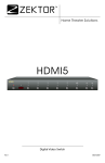
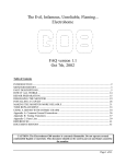
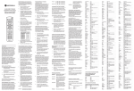
Clarity Elite 8x8
Component Video / Audio Matrix Switch
2
Clarity Elite 8x8 User Guide, Version 1.5b, 3/25/10
What’s Inside. . . . . . . . . . . . . . . . . . . . . . . . . . . . . . . . . . . . . . . . . . . . . . . . . . . . . . . .5
Thank you for your purchase! . . . . . . . . . . . . . . . . . . . . . . . . . . . . . . . . . . . . . . . . . . . . . . . . . . . . . . . . 5
Features. . . . . . . . . . . . . . . . . . . . . . . . . . . . . . . . . . . . . . . . . . . . . . . . . . . . . . . . . . . . . . . . . . . . . . . . . 5
Overview . . . . . . . . . . . . . . . . . . . . . . . . . . . . . . . . . . . . . . . . . . . . . . . . . . . . . . . . . . .6
Front Panel Controls . . . . . . . . . . . . . . . . . . . . . . . . . . . . . . . . . . . . . . . . . . . . . . . . . . . . . . . . . . . . . . . 6
Rear Panel Connections . . . . . . . . . . . . . . . . . . . . . . . . . . . . . . . . . . . . . . . . . . . . . . . . . . . . . . . . . . . . 7
Front Panel Commands . . . . . . . . . . . . . . . . . . . . . . . . . . . . . . . . . . . . . . . . . . . . . . .8
Turning the Clarity Elite 8x8 on or off. . . . . . . . . . . . . . . . . . . . . . . . . . . . . . . . . . . . . . . . . . . . . . . . . . . 8
Mapping an input to an output zone. . . . . . . . . . . . . . . . . . . . . . . . . . . . . . . . . . . . . . . . . . . . . . . . . . . . 8
Using the Audio/Video Breakaway. . . . . . . . . . . . . . . . . . . . . . . . . . . . . . . . . . . . . . . . . . . . . . . . . . . . . 9
Volume, Balance, Tone Controls and Gains . . . . . . . . . . . . . . . . . . . . . . . . . . . . . . . . . . . . . . . . . . . . 10
Input Gain Adjustments . . . . . . . . . . . . . . . . . . . . . . . . . . . . . . . . . . . . . . . . . . . . . . . . . . . . . . . . . . . . 11
Composite Converter Controls. . . . . . . . . . . . . . . . . . . . . . . . . . . . . . . . . . . . . . . . . . . . . . . . . . . . . . . 12
Using Presets - Setup Mode . . . . . . . . . . . . . . . . . . . . . . . . . . . . . . . . . . . . . . . . . . . . . . . . . . . . . . . . 13
Using Presets - Selecting a Preset, and Toggling “Client Mode” . . . . . . . . . . . . . . . . . . . . . . . . . . . . . 14
IP Address and Baudrate Selection . . . . . . . . . . . . . . . . . . . . . . . . . . . . . . . . . . . . . . . . . . . . . . . . . . . 15
Rear Panel Connections . . . . . . . . . . . . . . . . . . . . . . . . . . . . . . . . . . . . . . . . . . . . .16
Video Connections. . . . . . . . . . . . . . . . . . . . . . . . . . . . . . . . . . . . . . . . . . . . . . . . . . . . . . . . . . . . . . . . 16
Audio Connections. . . . . . . . . . . . . . . . . . . . . . . . . . . . . . . . . . . . . . . . . . . . . . . . . . . . . . . . . . . . . . . . 17
Audio Conversions. . . . . . . . . . . . . . . . . . . . . . . . . . . . . . . . . . . . . . . . . . . . . . . . . . . . . . . . . . . . . . . . . . . . . .
Dolby 5.1 Digital, and DTS Audio Handling . . . . . . . . . . . . . . . . . . . . . . . . . . . . . . . . . . . . . . . . . . . . . . . . . .
Using Volume and Tone Controls . . . . . . . . . . . . . . . . . . . . . . . . . . . . . . . . . . . . . . . . . . . . . . . . . . . . . . . . . .
Using Input Gain Settings . . . . . . . . . . . . . . . . . . . . . . . . . . . . . . . . . . . . . . . . . . . . . . . . . . . . . . . . . . . . . . . .
Using Output Gain Settings. . . . . . . . . . . . . . . . . . . . . . . . . . . . . . . . . . . . . . . . . . . . . . . . . . . . . . . . . . . . . . .
17
18
18
18
18
Specifications . . . . . . . . . . . . . . . . . . . . . . . . . . . . . . . . . . . . . . . . . . . . . . . . . . . . . .19
Clarity Elite 8x8 Serial Protocol, Version 1.5b, 3/25/10
3
4
Clarity Elite 8x8 Serial Protocol, Version 1.5b, 3/25/10
What’s Inside
What’s Inside
Thank you for your purchase!
Thank you for your purchase of the Clarity Elite 8x8 Audio/Video Matrix switch.
Every care has been taken to assure you of a successful installation and the subsequent operation of
your new Clarity Elite 8x8 video switch, however should something go wrong, and warranty repair
work is needed, we request that you hold on to the original packaging materials.
Please take this time to verify the contents of the Clarity Elite 8x8 box.
The following should be included:
•
Clarity Elite 8x8 Audio/Video Matrix Switch
•
Power Cord
•
USB Drive
•
Quick Start User Guide
If anything is missing please get in touch with us as soon as possible so that we can correct the situation.
Features
•
8x8 active matrix switch, with 3 additional composite inputs.
•
Ultrawide, DC coupled, video bandwidth: 0-450MHz.
•
Switches component video, analog audio, coax and optical digital audio.
•
All audio types supported (analog, coax and optical digital).
•
Auto converts between all formats of audio.
•
480i through 1440p60 resolution, including 1080p24 and 1080p60.
•
High current outputs for driving 300+ feet of cable.
•
Serial, IR, TCP/IP control.
•
Hardwired IR jack, any polarity, modulated or unmodulated, opto-isolated.
•
All discrete codes available including on, off, and codes for mapping any input to any output.
•
100 presets with easy to use Client Mode, that changes front panel operation to “presets only”.
•
Made in U.S.A.
•
Five year warranty.
Clarity Elite 8x8 User Guide, Version 1.5b, 3/25/10
5
Overview
Overview
Front Panel Controls
H
I
J
K
AUDIO VIDEO MATRIX SWITCH
MEM
1
2
3
4
VID
AUD
CLR
A
B
C
5
6
7
8
D
ENT
E
1
F
2
3
4
5
6
7
8
G
A Power toggle / Extended functions button.
B Window for IR sensor.
C Clear button and memory buttons.
D Input selection buttons 1-8.
E Enter button.
F Audio / video breakaway selection button.
G Zone selection buttons 1-8.
H Power indicator / IR received.
I Select composite inputs by pressing and holding buttons 1 - 3 for one second.
J Audio / video breakaway LEDs.
K Current input mappings for each zone.
6
Clarity Elite 8x8 User Guide, Version 1.5b, 3/25/10
Overview
Rear Panel Connections
A
C
B
1
2
3
6
7
8
1
2
VIDEO OUTPUTS
4
5
6
3
7
WWW.ZEKTOR.COM SAN DIEGO, CA USA
8
1
100-240V 0.35A MAX
50-60 Hz
2
3
OPTICAL INPUTS
4
5
6
7
8
B/Pb
COMPOSITE / S-VIDEO INPUTS
A
G/Y
1
ANALOG AUDIO INPUTS
ANALOG AUDIO OUTPUTS
1
3
5
7
1
3
5
7
2
4
6
8
2
4
6
8
G
L
R
L
R
L
R
L
R
L
R
H
L
R
I
L
C
2
1
E
2
S/PDIF INPUTS
RS232 / RS422
R
F
VIDEO INPUTS
4
5
E
R/Pr
I/R INPUT
TCP/IP
INPUT
D
R
L
1
2
S/PDIF OUTPUTS
1
3
5
7
1
3
5
7
2
4
6
8
2
4
6
8
J
K
L
A Power receptacle.
B Hardwired IR jack. Optical isolated, polarity insensitive, 3V to 15V levels.
C Component video inputs.
D Component video outputs.
E Optical digital audio inputs.
F TCP/IP connection.
G RS-232 / RS-422 connection.
H Analog audio inputs.
I Analog audio outputs
J Coax digital audio inputs.
K Coax digital audio outputs.
L Composite to component transcoders’ inputs.
Clarity Elite 8x8 User Guide, Version 1.5b, 3/25/10
7
Front Panel Commands
Front Panel Commands
Turning the Clarity Elite 8x8 on or off
A To power on the Clarity Elite 8x8 press the POWER toggle button.
To power off the Clarity Elite 8x8, press and hold the POWER button, for about 2 seconds, until the
Clarity Elite 8x8 powers off.
Mapping an input to an output zone
D
AUDIO VIDEO MATRIX SWITCH
MEM
1
2
3
4
VID
AUD
CLR
A
5
6
7
8
B
ENT
1
2
3
4
5
6
7
8
C
To map any input to any zone (output):
1
Select the zone or zones to be mapped by pressing one or more of the zone buttons C . When
a zone is selected the zone’s LED D will flash (allowing the selection to be seen easily from
across the room) and its decimal point will light up. By pressing a flashing zone’s button
again, you can unselect the zone.
2
Once a zone (or zones) have been selected, pressing an input button B , maps the chosen
input to the selected zone(s). By pressing and holding buttons 1 - 3, the composite to component converters A, C and E can be selected.
3
The zone LED(s) will stop flashing, but will remain selected, (the decimal point will remain
lit). To remap the currently selected zone(s) to a different input, simply press another input
button.
Since there are only 8 audio inputs and 11 video inputs, when switching to the three composite to component converters, the video break away feature is automatically enabled, and only the video will
switch to the converters. The audio will remain at it’s current setting.
Audio and video inputs will only change when the proper VID and AUD LEDs are lit, see the next section
on audio / video break away for more information.
8
Clarity Elite 8x8 User Guide, Version 1.5b, 3/25/10
Front Panel Commands
Using the Audio/Video Breakaway
AUDIO VIDEO MATRIX SWITCH
MEM
1
2
3
4
VID
AUD
CLR
5
6
7
8
ENT
1
2
3
4
5
6
7
8
A
The Clarity Elite 8x8 has an audio / video breakaway feature that allows the audio and video signals to
be switched independent of each other.
To switch only the audio channels of a zone (audio breakaway):
1
Press the audio / video breakaway selection button A until only the AUD LED is lit.
2
Following the instructions for “Mapping an input to an output zone”. When only the AUD LED
is lit, only the audio channels will change when mapping an input to an output zone.
To switch only the video channels of a zone (video breakaway):
1
Press the audio / video breakaway selection button A until only the VID LED.
2
Following the instructions for “Mapping an input to an output zone”. When only the VID LED
is lit, only the video channels will change when mapping an input to an output zone.
To switch both the audio and video channels of a zone (normal operation):
1
Press the audio / video breakaway selection button A until the AUD and the VID LEDs are lit.
2
Following the instructions for “Mapping an input to an output zone”. When both the AUD and
the BLUE LEDs are lit, both the Audio and Video channels will change when mapping an input
to an output zone.
Clarity Elite 8x8 User Guide, Version 1.5b, 3/25/10
9
Front Panel Commands
Volume, Balance, Tone Controls and Gains
F
C
G
AUDIO VIDEO MATRIX SWITCH
MEM
1
2
3
4
VID
AUD
CLR
A
B
5
6
C
7
8
D
ENT
1
2
3
C
4
5
6
7
8
E
The Volume, Balance, Bass, Treble, 5 Band Graphic Equalizers, Master Volume, and Zone Gain can
all be adjusted through the front panel, using the extended setup modes of the Clarity Elite 8x8. To
make the adjustments:
1
Enter the setup mode to by pressing and releasing the power toggle button A , the display will
fill with ‘-’ characters, indicating you are now in the extended setup mode.
To exit the setup mode, at any time, press the power toggle button A . The Clarity Elite 8x8
will return to normal operation.
10
2
Enter the Volume Update mode by pressing the in select ‘1’ button F . The display will now
show the selected zone, and the current volume level of that zone.
3
To increase the volume, use the input select button ‘4’ G .
4
To decrease the volume, use the input select button ‘8’ D .
5
By using the buttons labeled C , you can choose between the different settings. The buttons
are mapped as:
•
•
•
•
•
•
•
•
•
•
•
Press the ‘1’ button to control Volume, (0dB to -100dB range).
Press and hold the ‘1’ button to control the Master Volume, (+24dB to -100dB range).
Press and hold the ‘2’ button to control the zone’s output gain (+/-24dB range).
Press the ‘2’ button to control Bass, (+/-20dB range).
Press the ‘3’ button to control Treble, (+/-20dB range).
Press the ‘5’ button to control the Eq1 band 100Hz, (+/-20dB range).
Press the ‘6’ button to control the Eq2 band 330Hz, (+/-20dB range).
Press the ‘7’ button to control the Eq3 band 1,000Hz, (+/-20dB range).
Press the ‘ENT’ button to control the Eq4 band 3,300Hz, (+/-20dB range).
Press the AUD/VID button to control the Eq5 band 10,000Hz, (+/-20dB range).
Press the ‘MEM’ button to control Balance, (-200=max left, +200=max right).
•
Press and hold the AUD/VID button to adjust input gains (more on next page)
6
Pressing the ‘CLR ’ button B , will reset tone, equalizer, balance and gain controls to 0dB.
7
Select between zones by pressing the zone select buttons E
Clarity Elite 8x8 User Guide, Version 1.5b, 3/25/10
Front Panel Commands
Input Gain Adjustments
C
E
AUDIO VIDEO MATRIX SWITCH
MEM
1
2
3
4
VID
AUD
CLR
A
B
5
6
7
8
ENT
F
1
G
2
3
4
5
6
7
8
H
To adjust input gains, start by entering the volume control mode, select a listening zone, and then listening to that zone, adjust each of the input gains:
1
Enter the setup mode to by pressing and releasing the power toggle button A , the display will
fill with ‘-’ characters, indicating you are now in the extended setup mode.
To exit the setup mode, at any time, press the power toggle button A . The Clarity Elite 8x8
will return to normal operation.
2
Enter the Volume Update mode by pressing the in select ‘1’ button C . The display will now
show the selected zone, and the current volume level of that zone.
3
Use the zone buttons H to pick a zone. This will be the zone you will use to judge the input
gain levels.
4
Press and hold the AUD/VID button G to enter the input gain adjustment mode.
5
The zone buttons H are now used to switch between inputs, not zones!
6
There are separate gain settings for the digital inputs (coax and optical), and the analog inputs.
Digital input gains are indicated by a ‘di’ displayed in the zone 3 & 4 LEDs, analog input
gains are indicated by a ‘An’ in the 3 & 4 LEDs. Initially the selected input type (digital or
analog) will be depend upon which of the two has active audio (digital has priority over analog, if both have active audio on the inputs). You can toggle between the digital and analog
gain settings by pressing the VID/AUD G button. This allows you to adjust the dB levels of
the other setting - even though you cannot hear it. (To hear the analog audio you must disconnect the digital input, since digital audio has priority over analog audio.)
7
To increase the gain, use the input select button ‘4’ E . To decrease the gain, use the input
select button ‘8’ F . Pressing the ‘CLR ’ button B , will reset the input gain to 0dB.
8
You can jump back to the volume mode by pressing the ‘1’ button C
Clarity Elite 8x8 User Guide, Version 1.5b, 3/25/10
11
Front Panel Commands
Composite Converter Controls
C
G
AUDIO VIDEO MATRIX SWITCH
MEM
1
2
3
4
VID
AUD
A
CLR
5
6
B
F
C
7
8
D
ENT
1
C
2
3
4
5
6
7
8
E
The default input or input type, contrast, brightness, color saturation, and color hue can all be adjusted
through the front panel, using the extended setup modes of the Clarity Elite 8x8. To make the adjustments:
1
Enter the setup mode to by pressing and releasing the POWER button A , the display will fill
with ‘-’ characters, indicating you are now in the extended setup mode.
To exit the setup mode, at any time, press the POWER button A . The Clarity Elite 8x8 will
return to normal operation.
2
Enter the Composite Update mode by pressing the in select ‘6’ button F . The display will
now show the contrast of composite converter ‘A’.
3
To increase the contrast, use the input select button ‘4’ G .
4
To decrease the contrast, use the input select button ‘8’ D .
5
By using the buttons labeled C , you can choose between default input or input type, contrast,
brightness, saturation, and hue adjustments. The buttons are mapped as:
•
•
•
•
•
6
Select between inputs by pressing the zone select buttons E
•
•
•
12
Press the ‘1’ button to select input, (1=Input-1, 2=Input-2, S-video).
Press the ‘2’ button to control contrast.
Press the ‘3’ button to control brightness.
Press the ‘5’ button to control color saturation.
Press the ‘6’ button to control color hue.
Press the ‘1’ zone button to select the ‘A’ converter.
Press the ‘2’ zone button to select the ‘C’ converter.
Press the ‘3’ zone button to select the ‘E’ converter.
Clarity Elite 8x8 User Guide, Version 1.5b, 3/25/10
Front Panel Commands
Using Presets - Setup Mode
G
AUDIO VIDEO MATRIX SWITCH
MEM
1
2
3
4
VID
AUD
CLR
A
B
5
6
7
8
ENT
C
D
1
2
E
3
4
5
6
7
8
F
The Clarity Elite 8x8 is capable of memorizing 100 presets.
A preset is a configuration of inputs to zone mappings. Each preset can affect a single zone, or multiple
zones, and supports full audio/video breakaway. To configure a preset, do the following steps:
1
Start by mapping the inputs to the zones in any manner you like, this includes any audio/video
breakaway settings. Only the zones that you want the preset to affect, need to be setup.
2
Once the desired zones have been mapped, press and hold the MEM button G , the ENT LED
will start to flash, indicating you are now in the MEM setup mode.
To exit the preset setup mode at any time, press the POWER button A .
3
Zone LEDs now indicate the sources that will be mapped when the setup key is pressed. You
can turn off zones that you don’t want affected by the preset, by pressing a zone button F .
Each zone’s video and audio setting are turned on/off individually. The VID / AUD LEDs
indicate whether you are viewing the video mappings, or the audio mappings. When a zone
LED has its decimal point lit, this indicates the audio and video settings do not match (one of
the audio or video settings is turned off, while the other is turned on). Toggle the VID / AUD
LEDs using the VID/AUD button E to choose between the video/audio settings.
To completely turn off a zone’s video and audio (so that the preset will have no affect on the
zone), you must turn off the zone while the VID LED is lit, toggle the VID/AUD LED, and
then turn off the zone while the AUD LED is lit. The decimal point will also turn off, indicating both the VID and AUD selections match.
4
Once all zones you want to change are lit up, (and likewise all zones you don’t want affected
by the preset are turned off), press the ENT D button. The display will now prompt you to
choose which preset you want to program.
Use the source buttons C to enter the number of the preset you want to program. Use the
CLR button B to enter a ‘0’. Use the VID/AUD toggle button E to enter a ‘9’.
The presets 01-20 are available on the front panel, the next section shows you how the preset
numbers of each front panel button, are mapped.
5
Once the desired preset is being displayed, press the ENT button D to save the new configuration into the displayed preset.
Clarity Elite 8x8 User Guide, Version 1.5b, 3/25/10
13
Front Panel Commands
Using Presets - Selecting a Preset, and Toggling “Client Mode”
G
AUDIO VIDEO MATRIX SWITCH
MEM
1
2
3
4
VID
AUD
CLR
A
B
5
6
7
C
8
ENT
D
1
2
3
E
4
5
6
7
8
F
Once presets have been setup, using the preset is a simple manner of prefixing any button with the
MEM button. To select a new preset:
1
Press the MEM button G . The VID / AUD LEDs will start blinking, indicating the Clarity
Elite 8x8 is waiting for a preset.
2
Now pressing any button on the front panel, except power, will recall the configuration memorize by that preset. Pressing the power button A will cancel the preset mode and nothing will
be changed.
3
The front panel buttons are mapped to the presets as follows:
•
Input buttons 1-8 C are mapped as presets 01-08.
•
Zone buttons 1-8 F are mapped as presets 11-18.
•
The ENT button D is preset 09.
•
The VID/AUD button E is preset 10.
•
The MEM button G is preset 19.
•
The CLR button B is preset 20.
Another way of using the front panel buttons as presets is to enter the Client Mode. The Client Mode
locks the front panel into a mode where every button is a preset. No other functionality is available
(except power off, and the ability to leave Client Mode). To toggle the Client Mode:
14
1
Press and hold the ENT button D . While continuing to hold the ENT button, press the MEM
button G . The ENT LED will light, this indicates you are in the Client Mode.
2
Repeating step 1 will toggle you out of the Client Mode and return you to normal functionality.
Clarity Elite 8x8 User Guide, Version 1.5b, 3/25/10
Front Panel Commands
IP Address and Baudrate Selection
H
I
AUDIO VIDEO MATRIX SWITCH
MEM
1
2
3
4
VID
AUD
CLR
A
5
6
B
7
8
ENT
1
2
3
C
D
E
F
G
4
5
6
7
8
To adjust the IP address:
1
Enter the setup mode to by pressing and releasing the power toggle button A , the display will
fill with ‘-’ characters, indicating you are now in the extended setup mode.
To exit the setup mode, at any time, press the power toggle button A . Any changes made will
be lost! The Clarity Elite 8x8 will return to normal operation.
2
Enter the communication setup mode by pressing the in select ‘5’ button B . The display will
now show the upper two octets of the IP address.
3
The IP address is made up of four “octets”, the default IP address of the Clarity Elite 8x8 is:
192.168.001.200. Each octet is a number between 0 and 255.
To switch between displaying the upper two octets and the lower two octets, use the ‘4’ I
and ‘8’ C buttons. Use the zone buttons under each octet to adjust the value:
•
Any zone button under an octet in the 1’s position G will increment the value by 1.
•
Any zone button under an octet in the 10’s position F will increment the value by 10.
•
Any zone button under an octet in the 100’s position E will decrement the value by 1.
Values will wrap around. Incrementing past 255 will cause a value to wrap to 0. Decrementing
below 0 will cause the number to wrap around to 255.
4
Once set, you must press the ENT button D to save the IP address in non-volatile memory.
To change the serial port’s baudrate:
1
Perform above steps 1 and 2. The zone LEDs should now be displaying the upper two octets of
the IP address.
2
Press the source ‘1’ H button, the zone LEDs will now display the current baudrate setting.
There are two selectable baudrates, 19200 and 9600. The default baudrate is 19200.
3
To switch between the two baudrates, use the ‘4’ I and ‘8’ C buttons.
4
Once set, you must press the ENT button D to save the new baudrate in non-volatile memory.
Clarity Elite 8x8 User Guide, Version 1.5b, 3/25/10
15
Rear Panel Connections
Rear Panel Connections
Video Connections
A
100-240V 0.35A MAX
50-60 Hz
1
2
3
VIDEO INPUTS
4
5
6
7
8
1
2
C
VIDEO OUTPUTS
4
5
6
3
7
WWW.ZEKTOR.COM SAN DIEGO, CA USA
8
1
R/Pr
2
B/Pb
3
OPTICAL INPUTS
4
5
6
7
8
COMPOSITE / S-VIDEO INPUTS
A
G/Y
1
ANALOG AUDIO INPUTS
I/R INPUT
TCP/IP
INPUT
B
ANALOG AUDIO OUTPUTS
1
3
5
7
1
3
5
7
2
4
6
8
2
4
6
8
L
R
L
R
L
R
L
R
L
R
L
R
L
1
E
2
S/PDIF INPUTS
RS232 / RS422
R
C
2
R
L
1
2
S/PDIF OUTPUTS
1
3
5
7
1
3
5
7
2
4
6
8
2
4
6
8
The Clarity Elite 8x8 can switch 8 component inputs A , 3 composite to component converters C to
8 component outputs B , effectively making it an 11x8 video matrix switch.
Each component path is rated at 450MHz, and is DC coupled on the inputs and outputs.
The composite inputs are fed to composite to component converters that transcode composite (or svideo) to 480i component video. Each composite converter can be set to accept composite video on its
input 1, or input 2. Alternatively a composite to component converter can accept s-video by using a svideo to RCA splitter cable. The ‘Y’ cable of the splitter is connected to the ‘1’ input of a converter,
and the ‘C’ cable of the splitter is connected to the ‘2’ input.
16
Clarity Elite 8x8 User Guide, Version 1.5b, 3/25/10
Rear Panel Connections
Audio Connections
E
100-240V 0.35A MAX
50-60 Hz
1
2
3
6
7
8
1
2
VIDEO OUTPUTS
4
5
6
3
7
WWW.ZEKTOR.COM SAN DIEGO, CA USA
8
1
2
B/Pb
3
OPTICAL INPUTS
4
5
6
7
8
COMPOSITE / S-VIDEO INPUTS
A
G/Y
1
ANALOG AUDIO INPUTS
I/R INPUT
TCP/IP
INPUT
VIDEO INPUTS
4
5
R/Pr
ANALOG AUDIO OUTPUTS
1
3
5
7
1
3
5
7
2
4
6
8
2
4
6
8
L
R
L
R
L
R
L
R
A
L
R
L
R
L
1
E
2
S/PDIF INPUTS
RS232 / RS422
R
C
2
R
L
B
1
2
S/PDIF OUTPUTS
1
3
5
7
1
3
5
7
2
4
6
8
2
4
6
8
C
D
The Clarity Elite 8x8 accepts 8 channels of analog audio A , or 8 channels of coax digital audio C ,
or 8 channels of optical digital audio E as it’s inputs.
Available outputs are analog audio B , and coax digital audio D .
Audio Conversions
By default, the Clarity Elite 8x8 converts all analog audio to digital audio, and all digital audio to analog audio. It also converts all optical audio to coax audio.
The order of priority, starting from the lowest priority, are:
ANALOG AUDIO
If no other audio signal is present, then the analog inputs will be used. Analog audio is converted to digital audio and will be available as digital audio on the coax outputs, and as analog
audio on the analog outputs.
Volume and tone controls will affect both digital and analog audio outputs.
OPTICAL DIGITAL AUDIO
The optical inputs override the analog audio inputs. When present, the optical digital audio
will be converted to coax digital audio, and analog audio. The audio will be available as digital
audio on the coax outputs, and as analog audio outputs.
Volume and tone controls will affect both digital and analog audio outputs.
COAX DIGITAL AUDIO
The coax inputs override the optical inputs, and the analog audio inputs. When present, the
coax digital audio will be converted analog audio. The audio will be available as digital audio
on the coax outputs, and as analog audio outputs.
Volume and tone controls will affect both digital and analog audio outputs.
Clarity Elite 8x8 User Guide, Version 1.5b, 3/25/10
17
Rear Panel Connections
Dolby 5.1 Digital, and DTS Audio Handling
The Clarity Elite 8x8 does not decode compressed digital audio streams. When any digital audio that is
not standard PCM audio is detected, the Clarity Elite 8x8 switches to a digital pass through mode with
the following features:
•
Digital data is passed through unchanged by the Clarity Elite 8x8.
•
The analog audio inputs become active, and analog audio is passed through to the analog outputs.
•
Volume and tone controls will affect only the analog audio outputs.
Using Volume and Tone Controls
The factory default settings for master volume and individual zone volumes is 0dB. The factory
defaults for input gain settings is 0dB. The factory defaults for all tone and equalizer settings is 0dB.
By setting all gains and tone controls to 0dB the factory default for audio is pass through. Audio is
unchanged from inputs to outputs.
This leads to a caveat when using the tone and equalizer controls of the Clarity Elite 8x8. When adjusting the tone or equalizer controls it’s easily possible to exceed the 0dB threshold.
The S/PDIF standard’s maximum level is 0dB. Depending upon the level of signals coming into the
Clarity Elite 8x8, it’s quite possible, with gain and tone controls to exceed this, causing the signal to
clip, in turn causing a very unpleasant crackling and popping type of distortion.
If you choose to use the tone and equalizer settings of the Clarity Elite 8x8, it is highly recommend that
you lower the Master Volume at least -12dB, and possibly lower if you plan on using the full +20dB
range of the tone and equalizer settings. This will prevent the S/PDIF digital audio (and analog outputs) from clipping.
Using Input Gain Settings
The same warning given above for Volume and Tone controls also apply to the input gain settings.
The input gain settings can be used to amplify an input a full +24dB, well beyond the S/PDIF standard
of 0dB.
The input gain settings should be used to bring a weak signals up to the 0dB point, but should not be
used to increase the levels beyond that.
Using Output Gain Settings
Output gains settings allow adjusting the overall gain of each individual zone.
Different amplifiers require different audio levels to drive them to their full power ratings. Using the
output gain settings you can adjust each zone’s output level to match the sensitivity of your power
amplifier.
This also balance the volume of each room so that the same volume level, sounds the same in each
room.
The range of the output gain is +/-24dB, this value is added to any input gain, allowing for a full
+48dB of gain through the Clarity Elite 8x8, and this doesn’t take into account the tone controls, which
are added to this value. This is way beyond the gain needed for any power amp, so use care when
adjusting gains; +48dB of gain will cause nearly any input signal to be driven to distortion.
18
Clarity Elite 8x8 User Guide, Version 1.5b, 3/25/10
Specifications
Specifications
Video
Bandwidth. . . . . . . . . . . . . . . . . . . . . . . . . . . . . . . . . . . . . 0Hz-450MHz @ +0/-3dB, driving 75 ohms
Differential Gain Error (dG) . . . . . . . . . . . . . . . . . . . . . . . . . . . . . . . . . . . . . . . . . . . . . . . . . . 0.008%
Differential Phase Error (dP) . . . . . . . . . . . . . . . . . . . . . . . . . . . . . . . . . . . . . . . . . . . . . . . . . . 0.01%
Input coupling. . . . . . . . . . . . . . . . . . . . . . . . . . . . . . . . . D.C. (maximum allowable D.C. offset: 1.5V)
Output coupling . . . . . . . . . . . . . . . . . . . . . . . . . . . . . . . . . . . . . . . D.C. (D.C. offset less than 40mV)
Resolution . . . . . . . . . . . . . . . . . . . 480i - 1440p60, all HDTV modes, includes 1080p24 & 1080p60
Input impedance. . . . . . . . . . . . . . . . . . . . . . . . . . . . . . . . . . . . . . . . . . . . . . . . . . . . . . . . . . .75 ohms
Output impedance @ 0dB gain . . . . . . . . . . . . . . . . . . . . . . . . . . . . . . . . . . . . . . . . . . . . . . .75 ohms
Analog Audio
Analog inputs . . . . . . . . . . . . . . . . . . . . . . . . . . . . . . . . . . . . . . . . 8 Left / Right RCA connector pairs
Analog outputs . . . . . . . . . . . . . . . . . . . . . . . . . . . . . . . . . . . . . . . 8 Left / Right RCA connector pairs
Bandwidth. . . . . . . . . . . . . . . . . . . . . . . . . . . . . . . . . . . . . . . . . . . . . . . . . . . . 5Hz-20KHz @ +/-0.1dB
Signal to noise ratio . . . . . . . . . . . . . . . . . . . . . . . . > 85dB, 5Hz-20KHz unweighted, full analog path
Input impedance. . . . . . . . . . . . . . . . . . . . . . . . . . . . . . . . . . . . . . . . . . . . . . . . . . . . . . . . . 10K Ohms
0dB Output Voltage Level. . . . . . . . . . . . . . . . . . . . . . . . . . . . . . . . . . . . . . . . . . . . . . . . . . . . . 2V rms
Digital Audio
S/PDIF inputs . . . . . . . . . . . . . . . . . . . . . . . . . . . . . . . . . . . . . . . . . . . . . . . . . . . . . . 8 Coax, 8 Optical
S/PDIF outputs. . . . . . . . . . . . . . . . . . . . . . . . . . . . . . . . . . . . . . . . . . . . . . . . . . . . . . . . . . . . . 8 Coax
Signal to noise ratio . . . . . . . . . . . . . . . . . . . . . . . .> 110dB, 5Hz-20KHz unweighted, full digital path
Digital audio modes . . . . . . . . . . . . . . . . PCM in conversion mode. All others in pass through mode
Coax input levels . . . . . . . . . . . . . . . . . . . . . . . . . . . . . . . 200mV - 7.0V (PC soundcard compatible)
Coax output level . . . . . . . . . . . . . . . . . . . . . . . . . . . . . . . . . . . . . . . . . . 500mV nominal @ 75 Ohms
Audio Control
Volume range . . . . . . . . . . . . . . . . . . . . . . . . . . . . . . . . . . . . . . . . . . . .0dB to -99.5dB in 0.5dB steps
Master volume range . . . . . . . . . . . . . . . . . . . . . . . . . . . . . . . . . . . .+24dB to -99.5dB in 0.5dB steps
Full mute. . . . . . . . . . . . . . . . . . . . . . . . . . . . . . . . . . . . . . . . . . . . . . . . . . . . . . . . . . . . . . . . . . -115dB
Input gain range . . . . . . . . . . . . . . . . . . . . . . . . . . . . . . . . . . . . . . . . . +24dB to -24dB in 0.5db steps
Output gain range. . . . . . . . . . . . . . . . . . . . . . . . . . . . . . . . . . . . . . . . +24dB to -24dB in 0.5dB steps
Maximum possible gain through audio path (excluding tone controls). . . . . . . . . . . . . . . . . . . +48dB
Balance range . . . . . . . . . .Each left or right channel adjustable from 0dB to -99.5dB in 0.5dB steps
Bass, Treble and Equalizer ranges . . . . . . . . . . . . . . . . . . . . . . . . . . -20dB to +20dB in 0.5db steps
Control
Serial port. . . . . . . . . . . . . . . . . . . . . . . 19200 8N1, USB serial cable compatible, K.I.S.S™ protocol
TCP/IP . . . . . . . . . . . . . . . . . . . . . . . . 10Mbps, Full Duplex, Raw TCP/IP Socket, K.I.S.S™ protocol
Front panel IR sensor. . . . . . . . . . . . . . . . . . . . . . . . . . . . . . . Modulation Frequency: 34KHz-42KHz
IR jack . . . . . . . . . . . . . . . . . . . . . 3V to 15V, any polarity, modulated or unmodulated, opto-isolated
Firmware . . . . . . . . . . . . . . . . . . . . . . . . . . . . . . . . . . . . . . . . . . . . . . Upgradable through serial port
Power and Dimensions
Mains voltage . . . . . . . . . . . . . . . . . . . . . . . . . . . . . . . . . . . . . . .90V-264V, 47Hz-63Hz, auto-sensing
Power requirements . . . . . . . . . . . . . . . . . . . . . . . . . . . . . . . . . . . . . . . . . . . . . . . . . . . . . . . . . . . 32W
Dimensions. . . . . . . . . . . . . . . . . . . . . . . Rack Mountable: 17"W x 9.75"D x 3.375"H (feet add 0.25")
Clarity Elite 8x8 User Guide, Version 1.5b, 3/25/10
19
Specifications
20
Clarity Elite 8x8 User Guide, Version 1.5b, 3/25/10