1
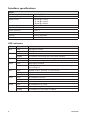
Interface specifications
Power
Rated voltage
Operating voltage
Rated current
Rated frequency
Power consumption
Inrush current l2t
Startup current
Polarity
Connection
12 to 48 VDC
10 to 60 VDC
130 mA @ 12 VDC
63 mA @ 24 VDC
40 mA @ 48 VDC
DC
2W
6 mA2 S
0.22 Apeak
Polarity dependent
32-pin Europe connector
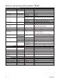
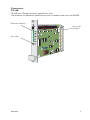
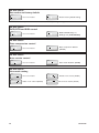
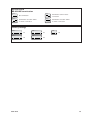
LED indicators
LED
RTS
RD
TD
DCD
REL
LINE
PWR
8
Status
OFF
ON
OFF
FLASH
OFF
FLASH
OFF
ON
OFF
ON
FLASH
OFF
ON
FLASH
OFF
ON
FLASH
Indication of
RTS signal is inactive
RTS signal is active
No data
The modem transmitting data on the DTE interface
No data
The modem receiving data on the DTE interface
DCD signal is inactive
DCD signal is active, modem has detected a carrier or the signal is
set to always on
Reliable mode is off, direct or normal mode
Reliable mode is on
Reliable mode with error correction and compression
The modem is on-hook
The modem is off-hook with a established connection
Line backup interface in use
The modem has no power
The modem is up and running
The modem is in the power-on selftest
6614-2210