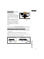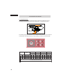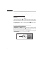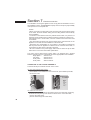
1
The Rosières Bocuse cooker
Operating instructions
44000571
BOCUSE
RBC 127 AUS
1-
Contents
Section 1
An introduction to your Rosières
Bocuse cooker
• key features at a glance
Section 2
Some words of caution
Section 3
How to use your
Rosières Bocuse cooker
• gas burners
• hob plate and griddle
• the left oven
• rotisserie
• the right oven
• oven accessories
• cooking hints
Section 4
Cleaning
• cast-iron hot plate
• stainless steel parts
• enamelled cast-iron
• gas burners
• stainless steel parts
• oven doors
• the oven light
• pyrolytic left oven
• catalytic right oven
-2
Section 5
Technical data and maintenance
Section 6
Installation
We recommend that your cooker
is installed by professional fitters
• connection to gas supply
This must be carried out by
a qualified gas fitter
• setting hob jets
• adjusting gas flame
• with option splash-back :
installation conditions
Section 7
Electrical connection
This must be carried out by
a qualified electrician
The cooker must be earthed
Welcome
…to the Rosières world of ‘cuisine complet’
The purpose of this user-guide is to introduce you to the many features
and benefits of your Rosières Bocuse cooker – and to welcome you to
our world of ‘cuisine complet’.
As someone who loves to cook, you now have before you, at your
fingertips, a cooker with the level of specification and performance which
satisfies the requirements of the most demanding professionals.
Originally designed for the internationally renowned chef Paul Bocuse,
it has been adapted for the domestic market.
Rosières have been manufacturing appliances which have won their
place at the heart of French cuisine since 1869 and
the Rosières Bocuse may be described as the only complete
cooker. It combines craftsmanship and innovation, putting the
technology of today at the service of the finest traditions of
the chef’s art.
So much more is put into the Rosières Bocuse – so you can get
so much more out of it.
Let your creative cooking have free rein and enjoy experiencing
the world of cuisine complet with your Rosières Bocuse.
Bon appetit!
3-
COOKER : RBC 127
-4
TOP LEFT
Ultra-rapid 4 kW safety gas burner,
with electronic ignition
The hot plate can be replaced
with the meat griddle
TOP RIGHT
4 safety gas burners with electronic
ignition
front left, ultra-rapid 3.5 kW
back left, semi-rapid 1.40 kW
front right, semi-rapid 1.40 kW
back right, rapid Mijorose simmer
safe burner 2.20 kW
LEFT OVEN
Electric
Multi-function, 7 cooking functions
Pyrolytic cleaning
Equipped with clock programmer
for controlling the cooking and
pyrolytic functions
Thermostat control indicator light
and pyrolytic cycle indicator
RIGHT OVEN
Electric
Conventional cooking with 4 cooking
functions
Oven, either catalytic or superenamel
Equipped with end of cooking timer
Thermostat control indicator light
Section 1 An introduction to your Rosières Bocuse cooker
Eager though you will be to start using your new Rosières Bocuse cooker, we
advise that you take time to get acquainted: after all, this is going to be a long
and creative relationship.
Using the key features illustration as your guide, familiarise yourself with each
part and function of the cooker which you will come to find offers you easy
access, flexibility, safety, economy, efficiency, with precise control of timing
and temperature.
As you will see from this initial inspection, the Rosières Bocuse gives you:
• Two full-sized electric ovens: Pyrolytic multi-function oven with diagonal
rotisserie left oven - catalytic conventional oven (right oven)
• Analogue clock programmer for multifunction oven
• End of cooking timer for conventional oven
• Flame failure device
• 4 gas burners with cast iron pan supports including Mijorose simmersafe
burner
• 4 kW Super gas burner with cast-iron pan and Wok support
• Cast-iron hotplate with griddle option
• Height adjustment feature to a maximum 90 cm
• Optional matching stainless steel splash-back
• Two convenient storage drawers for kitchen utensils and cooker accessories
As you begin using your Rosières Bocuse cooker you will find that its unrivalled
array of features, together in this one appliance, puts you in total control –
with all the advantages that brings.
Whether it involves baking or blanching, simmering or grilling, no recipe will
prove impossible. You will have your own favourites to try, of course. And to
extend your range, you will find Paul Bocuse cookery books available at good
bookshops.
5-
Section 2 Some words of caution
We want you to get maximum pleasure and benefit from your Rosières Bocuse
cooker. But before we guide you through its many features, permit us to offer.
a few important words of caution for your well-being and that of
your cooker.
We recommend that your cooker is:
• professionally installed
• it must be connected to the fuel supply by a qualified electrician
and gas fitter
• earthed
- For safety reasons under no circumstances should any modifications be
carried out to this appliance.
- All the accessible parts are hot when the cooker is in operation. Keep
young children away from the cooker when in use.
- Both the ovens are fitted with a multi-layered glass door to prevent the
possible risk of burns during operation (cooking modes). Nevertheless, we
recommend you keep young children well away from the ovens
especially during the left oven’s pyrolytic cleaning phase.
- Prior to pyrolytic cleaning, wipe off any large food spillages. Indeed,
excessive amounts of grease may catch fire under the intense pyrolytic
heat.
- Never use a steam or high-pressure spray to clean the ovens.
- If your oven shows even the smallest defect, do not connect it. Disconnect
it from the power supply and immediately contact an approved ROSIERES
service agent.
- Do not store flammable products in the cooker as they can catch fire if the
cooker is inadvertantly switched on.
- Do not lean on the oven doors or allow children to do so.
- Use oven gloves, when placing or removing a dish from the oven.
- After each use we recommend that some cleaning of the cooker, is
undertaken. This prevents the accumulation of dirt and grease which gets
re-cooked and burns, generating unpleasant smells and smoke.
- Do not line the oven walls with aluminium foil or single-use oven
protectors available from some stores. Aluminium foil or any other
protection, in direct contact with the hot enamel, risks melting the enamel or
causing deterioration to the inside.
- When cooking with fats or oils, always take care to watch the cooking
process as heated fats and oils can catch fire rapidly.
-6
Cast-iron hot plate: essential pre-treatment before first use
Caution: before using the hot plate for the first time, the following steps
must be taken:
• wash the plate with soapy water
• sprinkle salt over the plate and then buff in the salt with black and white
printed newspaper (not coloured)
• heat the salted plate, allow to cool, wipe off the salt
• using kitchen roll, wipe a thin layer of vegetable cooking oil over the top of
the hot plate
• turn on the burner to heat the hot plate for a few minutes
• this will produce some smoke, so switch on the extractor hood
• once the oil has disappeared, turn off the burner and let the hot plate cool
• give the plate a light wipe with vegetable oil
• leave to cool, the hot plate centre will turn light grey and the edges will
remain dark grey
• the hot plate is ready for use
Caution: Please read this guide thoroughly before first using your cooker.
Section 2
7-
Section 3 How to use your Rosières Bocuse cooker
We now come to the detailed practical guide to your cooker. We
describe each feature, its function, and how it can benefit you in your
cooking.
RECOMMENDATIONS...
- Do not use pans with a concave or convex bases. You can use a “Wok” as
long as you install the Wok support griddle supplied with the cooker.
- Avoid boiling food too quickly. A “high boil” doesn’t cook food any quicker,
and as the food is violently agitated this can cause it to loose its taste.
- Flames should not lick out from the pan base, this just means you are
wasting gas. Only the base of the pan should be heated. Do not allow
flames to project beyond this point. This means gas is being wasted.
- Do not place an empty pan on a lit gas burner.
Caution: when the burners are not in use, the main supply control
should be closed.
1
2
4
5
3
1-5 • SEMI-RAPID BURNER: use the smallest burner for small pans.
2 • RAPID BURNER: use this burner for stewing and sauces. With medium
rate, the flame is only in contact with the burner cap. Ideal for stewing, the
heat is distributed evenly under the pan. Food does not stick and there is no
crown effect in the bottom of the pan.
3 • MULTI PURPOSE HOT PLATE/SUPER BURNER: this burner provides
various uses. A handling tool supplied with the cooker lets you remove the
hot plate for adapting various components.
4 • ULTRA-RAPID BURNER: use this burner for bringing to the boil, sealing
meat, and generally for all foods that need to be cooked quickly.
For optimum burner utilisation, we recommend you use pans with diameters
not less than those detailed below:
Ultra-rapid
Semi-rapid
-8
ø 18 cm
ø 12 cm
Rapid
Open hob
ø 18 cm
ø 24 cm
USE
Each burner has electronic ignition and a thermocouple safety device that
automatically stops the gas if the flame goes out accidentally.
• Open the gas tap.
• A symbol near each knob lets you see which burner is in use.
• Press in and turn the gas tap to the
mark. Holding the knob in
creates the ignition spark. Continue pressing the knob in for two
seconds to set the safety device.
• Adjust the flame according to your cooking needs.
High
Low
• To stop the burner, set the knob to position"•".
Note:
If there is no electricity, the burner can be lit with a match.
If the flame goes out accidentally, reignite the burner.
MULTI PURPOSE BURNER
Caution: the cast iron hot plate and the griddle cook at high temperatures.
Please take extreme care and always keep children away. It is advisable
to allow the cast iron parts to cool before moving them. Always use the
lifting tool ensuring that the top of the tool is over the hot plate centre.
HOT PLATE: ideal for simultaneous cooking, for sauces,
lengthy stewing, or keeping foods warm. According to the
dish, you can adjust the setting either by the control knob
or by moving the pan over the cast iron plate. The
temperature at the plate centre reaches 400°C, towards
the outer edge the temperature decreases to 100°C for
traditional slow simmering.
GRIDDLE: for a brisk heat, etc.
WOK SUPPORT: for WOK, use or when using a convex
bottomed pan. It can be fitted to various burners.
Section 3
OPEN HOB: accommodates large quantities of food and
large pans. Remember to position the spacer and its core
for optimal operation.
9-
COOKING METHODS :
All cooking should be carried out with the door closed.
Defrost: The cooking fan runs circulating air inside the oven. Ideal
for defrosting before cooking.
Conventional cooking: Top and bottom heating elements are used
together. Preheat the oven for about ten minutes. This method is
ideal for all traditional roasting and baking. For sealing red meats,
roast beef, leg of lamb, game, bread, foil-wrapped food (papillotes),
flaky pastry. Mid shelf position recommended.
Fan cooking: Both top and bottom heating elements are used and
the fan circulates the air inside the oven. Recommended for poultry,
pastries, fish and vegetables. Heat penetrates the food better and
both the cooking and preheating times are reduced. Different foods
can be cooked at the same time in one or more positions. This
function provides even heat distribution and does not mix the smells.
Allow about ten minutes extra when cooking foods at the same time.
Lower element: Using the lower element. Ideal for cooking all pastry
based dishes. This allows you to cook dry tart pastry without over
cooking the fruit filling. Use this for flans, quiches, tarts, pâté and any
cooking that needs more heat and radiation from below.
Fan & Lower element: The bottom heating element is used in
conjunction with the fan which circulates the air inside the oven. This
method is ideal for moist fruit flans, tarts and pâté. It prevents food
from drying out and encourages rising cakes, bread dough and other
foods. Bottom cooking. Put the shelf at a lower shelf level
recommended.
Grill: Using the top level element. Success is guaranteed for mixed
grills, kebabs and au gratin dishes.
Five minutes preheating is required to get the element hot. Use the
grill when the door is closed. The right oven has two grill positions:
grill = 2140 W, grill with extra = 3000 W.
Fan assisted grilling: The top heating element is used in
conjunction with the fan circulating the air inside the oven. Ideal for
cooking thicker food stuffs, whole pieces of meat such as roast pork,
poultry, etc. Preheating is necessary for red meats but not for white
meats. Place the food to be grilled directly on the shelf centrally, at
the middle level. Slide the drip tray under the shelf to collect the
juices. Make sure that the food is not too close to the grill. Turn the
food over halfway through cooking.
Rotisserie: The top heating element is used in conjunction with the
rotisserie providing the real flavour of a traditional roast.
-10
LEFT OVEN
Clock programmer
Pyrolytic
cleaning
indicator
Thermostat
control indicator
Function selector
Thermostat knob
SETTING THE PROGRAMMER
The clock must be set before using the oven for the first time.
To set the time, press in and turn the button clockwise.
Move the clock’s hour and minute hands to the correct time.
USING THE LEFT OVEN
> Turn the function selector to the cooking position you want.
> Set the thermostat knob to the required temperature based on the
information below.
Defrost
Thermostat knob to stop position
Conventional cooking
from 60°C to 280°C
Fan cooking
from 60°C to 230°C
Fan + Lower element
from 60°C to 230°C
Grill
from 220°C to 275°C
Turbo grill
from 180°C to 230°C
Rotisserie
from 220°C to 275°C
> In order to operate the oven either set to manual ( symbol in window)
or automatic (cooking duration time displayed in window).
Before programming, the “C” pointer must be positioned under the hour hand, if
not: pull out and turn the button clockwise.
Pointer “C”
Hand position
Immediate programming
with a cooking duration
Section 3
In the hand position, or with a cooking duration displayed, the oven starts immediately, to set Manual symbol or time in window turn the button clockwise
without pulling it and release it.
11-
In hand position, the oven must be stopped manually by returning the function selector
and thermostat knobs to the stop position.
For programming with immediate start and cooking duration, the oven stops
automatically once the time has elapsed and an audible alarm sounds. To stop the
alarm, turn the button to display
in the little window.
Return the function selector and thermostat knobs to the stop position.
> The cooking start time can be delayed...
To set the start time: pull out and turn the button to the right to put the ‘C’ pointer to
the required starting time, and release it.
To set the cooking duration: turn the button clockwise, without pulling, to display
the time required to cook the food.
The oven starts at the programmed time and stops operating automatically once
the time has elapsed. The end of cooking time is signalled by an alarm that rings
for several minutes. To stop the alarm, turn the button to display
and return
the function selector and thermostat knobs to the stop position.
ROTISSERIE
This consists of one skewer, two forks and a spit holder.
. Take all the accessories out of the oven.
. Place the deep tray at the bottom.
. Put the food onto the skewer, and centre between the two forks.
. Put the skewer onto the holder.
. Slide the holder and skewer into the second shelf position from the bottom.
. The end of the turnspit should be opposite the opening of the drive device.
. Engage the turnspit in the drive device.
Fitting the turnspit diagonally:
-12
Œ
•
Ž
• Drive device
No preheating is required for Rotisserie cooking.
Rotisserie cooking is carried out with the door closed.
RIGHT OVEN
End of cooking
timer with
hand position
Thermostat
control indicator
Function selector
Thermostat knob
USING THE RIGHT OVEN
> Turn the function selector knob to the cooking position you require.
> Set the thermostat knob to the required temperature based on the
information below.
Conventional cooking
from 60°C to 280°C
Lower element
from 60°C to 230°C
Grill
from 220°C to 275°C
> Set the timer knob to the hand position or to a duration.
Note: to indicate a duration on the timer, turn the knob clockwise up to 120
minutes then return it to the required duration.
Hand position
Duration : 1-120 minutes
Whatever programming method is selected, the oven starts immediately.
In hand position, the oven must be stopped manually by returning the
function selector and thermostat knobs to the stop position.
When programming a duration, the oven stops automatically once the time
has elapsed.
The regulation indicator shows the use and operation of the thermostat. It comes on and goes off regularly throughout the cooking duration
time.
The pyrolytic cleaning indicator comes on as soon as the control
knob is on the P position and goes off when the oven temperature
rises to 300°C.
Section 3
INDICATORS
13-
COOKING HINTS
Temperatures and cooking times are given as guidance for oven use.
Personal experience should then let you adapt these settings to your own
taste.
Remember that cooking at higher temperatures causes more spattering,
and the oven becomes dirty causing smoke. It is better to slightly reduce the
cooking temperature, even if it means increasing the cooking time.
4
3
2
1
Oven walls are equipped with
different shelf positions numbered
from the bottom.
SHELF POSITION
FISH
Recipe
-14
Cooking
Quantity
Method
Cooking °C
Cooking
time
Shelf position
from bottom of
the oven
Trout or
Bream
Conventional
cooking
1 kg whole
220°C
30 min
1
Monk fish or
Salmon
Conventional
cooking
1 kg poached
220°C
30 min
1
Salmon steak
Fan cooking
6 pieces
140-160°C
10-15 min
1
Fillet of sole
Fan cooking
6 pieces
160°C
15-20 min
1
Grilled fish
Grill
6 fillets
275°C
2 X 5 min
4
MEAT
It is better not to salt meat until after cooking as salt encourages the meat
to spatter fat. This will dirty the oven and generate a lot of smoke.
Joints of white meat, pork, veal, lamb and fish can be put into a cold oven.
The cooking time is longer than for a preheated oven, but it cooks through
to the middle of the food as the heat has more time to penetrate.
Correct preheating is the basis of successful red meat cookery.
FOR GRILLING
Preparing for a mixed grill:
Remove the meat from the refrigerator a few hours before grilling. Lay it on
several layers of kitchen roll: this improves sealing, making it tastier and
ensures that it cooks right through to the centre.
Add pepper and spices to the meat before grilling, but add any salt after
cooking. This way it will seal and stay moist. Baste all the food to be cooked
with a little oil. This is best done with a wide flat basting brush. Then
sprinkle with more pepper and herbs.
Put the grill dish into the oven.
During cooking:
Never pierce the food during cooking, or when you turn it over: juice
runs out and the meat becomes dry.
Section 3
15-
MEAT
Recipe
Cooking
Method
Quantity
Cooking °C
Cooking
time
Beef with
carrots
Conventional
cooking
for 6
200-220°C
about 4 hr
Duck
Conv. cooking
1.5 kg
200-220°C
1½ hr
Turkey
Conv. cooking
5-6 kg
160-180°C
2½-3 hr
Goose
Conv. cooking
3-4 kg
160-180°C
2-2½ hr
Leg of lamb
Conv. cooking
200-220°C
15 min/pound
Roast chicken
Conv. cooking
220°C
about 1 hr
Roast beef
Conv. cooking
240°C
15 min/pound
Roast rabbit
Fan cooking
800 g – 1 kg 200-220°C
Roast white
meat
Fan cooking
200-220°C
40-50 min/kg
Boeuf
bourguignon
Lower element*
for 6
200°C
1½ hr
Cast-iron casserole
with lid
Chicken
casserole
Lower element*
1.5 kg
210°C
1½ hr
Cast-iron casserole
with lid
Veal/poultry
Rotisserie
1.2 kg
275°C
60-70 min/kg
No preheat required
Veal/poultry
Rotisserie
1 kg
275°C
45-50 min
No preheat required
Beef
Rotisserie
1 kg
275°C
15-20 min
No preheat required
Lamb/Mutton
Rotisserie
1 kg
275°C
20-25 min
No preheat required
Pork
Rotisserie
1 kg
275°C
45-50 min
No preheat required
Kebabs
Grill
6 pieces
275°C
2 x 8 min
Turn over half way
through cooking
Pork chop
Grill
6 pieces
275°C
2 x 8 min
Turn over half way
through cooking
1-1.5 kg
Hints
50-60 min
* for the fan and lower element cooking method, we recommend preheating with fan cooking.
All cooking was done at shelf position “1”.
-16
VEGETABLES – OTHERS
Recipe
Braised
cabbage
Cooking
Method
Quantity
Cooking °C
Cooking
time
Conv. cooking
for 6
200-220°C
1 hour
200-220°C
1 hour/kg
Pâté en croûte Conv. cooking
Hints
Chicory
with gruyere
Fan cooking
for 6
180-200°C
25-30 min
Jacket
potatoes
Fan cooking
for 6
200-220°C
about 1 hour
Soufflé, savoury
/sweet
Fan cooking
for 6
180-200°C
50-60 min
Stuffed
tomatoes
Fan cooking
6-8 pieces
200-220°C
40-45 min
Pilau rice
Lower element
300 g
200°C
25 min
Leek flan
Fan +
Lower element
for 6
220°C
35-40 min
Quiche
Lorraine
Fan
for 6
+ Lower element
220°C
45-50 min
Toast with
cheese*
Turbo grill
6 pieces
210°C
3 min to toast
one side +
4 min/cheese
Dauphiné
(cheese-topped Turbo grill
dish)*
6 portions
200°C
45 min
Oval dish
Sausages*
4 pieces
210°C
2 X 10 min
Turn over Half
way through
cooking
Flat pan
Turbo grill
mould Ø 22
Flat pan
All the cooking was done at shelf position “1” except cooking marked “*”, which requires cooking
at a middle shelf position.
17-
BAKING
Avoid using shiny tins as they reflect heat and can spoil your cakes. If your cakes brown too quickly,
cover them with grease-proof paper or aluminium foil. Caution: the correct way to use foil is with the
shiny side in towards the cake. If not the heat is reflected by the shiny surface and does not penetrate
the food.
Avoid opening the door during the first 20 to 25 minutes of cooking: soufflés, brioche, sponge cakes
will tend to fall.
You can check if cakes are done by pricking the centre with a knife blade or skewer. If the blade
comes out nice and dry, your cake is ready and you can stop cooking. If the blade comes out moist or
with bits of cake attached, continue baking but slightly lower the thermostat so that it is finished off
without burning.
Recipe
Cooking
Quantity
Method
Cooking °C
Cooking
time
Shelf level
Cake
Conv. cooking
1.5 kg
180-200°C
50-60 min
1
Fruit tart
in batter
Conv. Cooking
for 6
200-220°C
40-50 min
1
Pound cake
Conv. cooking
1.5 kg
200-220°C
45-50 min
1
Filled pie
Conv. cooking
for 6
200-220°C
40-45 min
1
Brioche
Fan cooking
800 g
200°C
40-45 min
1
Sponge cake
Fan cooking
180-200°C
35-40 min
1
Genoese cake Fan cooking
180-200°C
30-35 min
Hints
Ø 27
Ø 27
Ø 27
Ø 27
Choux pastry
Fan cooking
40 pieces
190°C
35 min
1 and 3
2 trays
Pastry base
Fan cooking
for 6
180-200°C
20-30 min
1
Ø 27
Puff pastry
e.g. bouchée
Fan cooking
6 pieces
200°C
15-20 min
1
Meringues
Fan
1 tray
+ Lower element*
80-85°C
4½ hours
1
Fruit tart
Fan
for 6
+ Lower element*
220°C
35-40 min
1
* with fan and lower element cooking method, we recommend at first a preheating with fan cooking to
save time.
-18
COOKER EQUIPMENT
THE MULTI PURPOSE HOT PLATE/SUPER BURNER AND ACCESSORIES
Hot plate
Hook
Griddle
Wok support
. 1 Hot plate for cooking food using large pans, for stews, sauces, etc.
. 1 Hook for removing the hot plate.
. 1 Griddle for brisk grilling.
. 1 Burner spacer with cast iron pan support for use when the burner is uncovered.
. 1 Wok support grill.
. 1 cast-iron pan support for open burner cooking.
OVENS
Flat shelf
Pastry tray
Tray holder shelf
Drip-tray
. 2 Flat shelves for supporting various dishes and moulds.
. 3 Pastry trays with 1 stainless steel tray that slide directly into the oven shelf
positions. They are for cooking small pastries, like choux, biscuits, meringues,
etc.
. 2 Tray holder shelves for supporting dishes or moulds. They can be combined
with drip-trays on slides.
. 2 Drip-trays to collect meat and grilling juices during roasting or grilling. They
can be put on the shelves, or slid under them. Unless used with the grill, the
drip-tray must not be stored in the oven while in use.
All unused accessories must be removed from the oven when it is in use.
Section 3
. 1 Flat shelf can be combined with the drip-tray for all
types of grilling. A handle is supplied for removing
grill pan from the oven without the risk of burning
yourself. Never leave the handle inside the oven.
19-
Section 4 Cleaning
Cleaning your Rosières Bocuse cooker
This section explains how to keep each part of your cooker clean and in peak
operating condition.
Before carrying out any cleaning, you must:
. disconnect the appliance from the electrical supply.
. wait for all the hot parts to cool.
Never use abrasive cleaners, wire wool or sharp objects to clean the top.
TOP LEFT
- Polished cast-iron plate: protective finish is applied to the cast-iron plate
when it leaves the factory. The finish can easily be removed using a strong liquid
detergent (ammonia based).
To clean it, rub the plate with fine emery paper to clear any rust spots. Wipe with a
slightly oily cloth to prevent rust forming. When in use, daily cleaning is required
to keep the top of the cast-iron plate looking good. General stores stock various
products for cleaning the polished top. For additional protection, we recommend
you clean the cast-iron top regularly with a slightly oily cloth.
- Enamelled cast-iron frame: when the cooker is cold, just clean using a nonabrasive liquid detergent, rinse and wipe off with a clean dry cloth. Cleaning hot
enamel risks tarnishing it.
TOP RIGHT
- Burner caps and pan supports in enamelled cast-iron: clean as described
above for the enamelled cast-iron frame.
- Gas burners: for normal cleaning, it is recommended to clean off all grease or
burnt-on deposits using ammonia or commercial, non-abrasive cleaners.
Do not put the burner caps straight into cold water after use in order to prevent
heat shock from rupturing the enamel. To conserve the original appearance of the
burner bodies, use a non-abrasive detergent, rinse and dry carefully. If the holes
are clogged, brush them with soapy water, rinse and dry.
When refitting these parts, make sure that each of them is wiped dry. Check that
each part is correctly positioned before using the cooker hob again.
- Caution: do not let water get inside the gas burners.
STAINLESS STEEL PARTS – clean with soft cloth and a special stainless
steel cleaner available from most department stores.
ENAMEL CAST-IRON PARTS - when the cooker is cold, clean using a nonabrasive liquid detergent, rinse and wipe off with a clean dry cloth.
-20
OVENS
. Whatever the cleaning method, do not let fatty residues accumulate inside the
oven. Clean it regularly.
. Never line the oven sides with aluminium foil or single-use commercial
protection; this concentrates the heat causing the enamel to deteriorate.
- Oven doors: the door can be cleaned in situe or can be removed.
. Remove as follows:
. fully open the door; the hinge appears as in photo 1;
. lift the hinge pins (photo 2) and pull the door upwards partially closing it until
released.
For installation, make sure you reposition the hinges carefully; a notch located
below them (photo 3) lets you fit the hinges correctly.
After the door is put back on its supports, fit the hinge pins in their initial position
as in photo 4.
1: initial position
with pin to bottom
2: lift the pin
3: hinge notch
<------------ Removal --------------------> <----------------- Installation -------------->
- Oven door glass: after each use of the oven, wipe using absorbent kitchen
roll. If there is a lot of spattering, clean the glass with a sponge and detergent.
Rinse and dry.
- Oven lighting:
Disconnect all power supplies from the oven before cleaning or replacing the
bulb. The bulb and its cover are made of material resistant to high temperatures.
Section 4
Bulb characteristics:
230 V AC - 25 W – Base E 14 - Temperature 300°C.
To change a defective bulb, just:
. unscrew and remove the glass cover,
. unscrew the bulb;
. replace it with the same type: see characteristics
above;
. after replacing the defective bulb, screw back the
protective glass cover.
21-
LEFT PYROLYTIC OVEN
Pyrolytic cleaning uses high temperatures to destroy soiling. The resulting
smoke is cleaned by passing through a catalyst. Because of the high
temperatures involved, the oven door has a safety lock that prevents it being
opened during pyrolytic cleaning.
When the pyrolytic cycle is running, you may notice a slight odours; its intensity
will depend on the amount of ventilation in the room.
IMPORTANT:
. It is important to clean off accumulated grease. Indeed, any grease deposits
may catch fire under the intense heat involved in pyrolytic cleaning.
. You are strongly advised not to use detergents or any other proprietary product
for cleaning ovens.
. Do not use the left-hand gas plate during pyrolytic cleaning.
• Before commencing pyrolytic cleaning:
. Remove all the accessories from the oven; they are likely to be damaged by
the heat generated during the pyrolytic cleaning process.
. Remove large spills of food or waste that would take too long to be carbonized.
. Close the door.
• Starting pyrolytic cleaning:
Turn the function selector to the P position.
Leave the thermostat knob on the ‘stop’ position.
• Display a cleaning duration on the programmer:
Before programming, check on the programmer that the pointer ‘C’ should be
positioned under the hour hand, if not: pull out and turn the button clockwise.
To set the cleaning duration,
turn the button clockwise
and then release it.
Pointer “C”
Immediate start and
pyrolytic cleaning time
Minor soiling: 90 min., medium soiling: 105 min., very soiled: 120 min.
With immediate start and duration programming, the oven stops automatically
once the time has elapsed and an audible alarm sounds to warn you. To stop the
alarm, turn the button to display
in the little window. Turn the function selector
knob to the stop position.
-22
• The pyrolytic cleaning cycle can be delayed...
Setting a programming start time: pull out and turn the button clockwise to
put the ‘C’ pointer to the starting time, and release it.
Displaying a duration: turn the button clockwise, without pulling it, to display
the time required for the pyrolytic cleaning cycle.
The oven starts at the programmed time and stops operating automatically
once the time has elapsed. The end of the time is signalled by a bell that
rings for several minutes. To stop the alarm, turn the button to display .
Return the function selector knob to the stop position.
Pyroysis leaves a white residue on the oven walls. Wait for the oven to cool
completely then clean the inside of the oven with a damp sponge to wipe off
the residue.
RIGHT CATALYTIC OVEN
OVEN WITH CATALYTIC WALLS – catalytic cleaning takes place while the oven
is in use. The oven walls are coated with a special enamel, micropores
encourage the combustion of grease. Each drop is eliminated by the combined
action of the catalytic enamel and heat.
• Regular cleaning: the accumulation of fine residual dust resulting from the
combustion of grease may eventually reduce the enamel’s efficiency.
To keep this enamel in peak condition, you should rinse the walls with very hot
water after every 10-15 roasts. This quick job is made all the easier as the side
walls can be fully removed to be washed in the sink. They are fixed by a central
screw (unscrewed by hand) on the top of the wall, and held by two tabs at the
bottom; release them by lifting.
After rinsing and installing the sides in the cooker, dry the enamel by operating
the oven at maximum position for ¼ hour.
Note: if after normal use, you notice slightly darker marks on the oven walls
don’t worry, this effect is quite normal, they are just grease marks in the
process of being eliminated.
ENAMEL OVEN – The oven has an enamelled surface when the catalytic side
walls are removed. Clean inside the oven with a sponge soaked in washing up
liquid and very hot water to remove hard grease marks. For heavy spattering use
commercially available oven cleaners.
Section 4
• If spills are large, the enamel should be cleaned to let it recover its
efficiency. Follow these steps:
. Wipe any big spills or deposits with a sponge soaked in very hot water, using
ammonia liquid detergent.
. Use a nylon brush on any marks that cannot be wiped away.
. Then heat the oven for an hour set at the maximum thermostat position.
. It may be necessary to repeat these operations several times, if the spillages
are heavy.
23-
Section 5 Technical data and maintenance
This section details the dimensions of the appliance, the hob power rating,
and the dimensions, power rating and power consumption of the two ovens.
RBC 127 AUS
Cooker dimensions
HOBS
Width 116,5 cm X Depth 61,5 cm
98 cm with back plate
TOP LEFT
front right
TOP RIGHT
semi-rapid 1,4 kW
front left
ultra-rapid 3,5 kW
back right
rapid simmer 2,2 kW
back left
semi-rapid 1,4 kW
Hot plate / super burner
burner 4 kW
OVENS
LEFT OVEN
RIGHT OVEN
48 litres
50 litres
43 X 37,5 X 30 cm
42,5 X 39,5 X 30 cm
Oven volume
Width X Depth X Height
Oven power under 230 V
Multi-funtion
Conventional cooking
40 W
-
Conventional cooking
2420 W
2420 W
Fan cooking
2450 W
-
-
1560 W
Fan + Lower element
1590 W
-
Gril
2140 W
2140 W
-
3000 W
Fan assisted grill
2170 W
-
Defrost
Lower element
Gril with extra
Rotisserie
2140 W
-
Pyrolytic cleaning
2410 W
-
Maximum power
2450 W
3000 W
Oven consumption
Rise to 200°C
0,50 kWh
0,45 kWh
Holding for 1 h at 200°C
0,60 kWh
0,65 kWh
3 kWh
-
Pyrolytic cleaning (80 minutes)
All data is given for information only. In order to improve the quality of its
products, ROSIERES may modify its appliances with technological
developments which adhere to the conditions set out in the Consumer Code.
Appliance compliant with Directives 89/336/EEC, 73/23/EEC,
89/109/EEC & 90/396/EEC.
-24
Section 6 Installation
The installation of household appliances is a delicate operation that, «if
not done correctly», can have serious consequences for consumer safety.
Therefore, this work must be entrusted to a professional who can carry
it out in compliance with the technical standards in force.
Rosières will not accept any responsibility in case of technical failure of
the product whether or not it causes damage to goods and/or persons if
the installation has not been carried out by a qualified engineer/gas
fitter.
• Before installation, the technician should:
. Check the compatibility between the cooker and the gas installation.
The cooker is factory set for use with the gas type as stated on the
packaging and repeated on the label affixed to the cooker.
. If necessary change the gas
To adapt the cooker fit suitable jets that provide the nominal flow rate and by
adjusting the air rings according to the information given on pages 26 to 28.
• For installation, the technician should:
. Install the cooker leaving a space of 1.5 cm on each side. The cooker is
Class 1; furniture adjacent to the unit must not be higher than the top of the
cooker. The cooker has five adjustable feet for perfect levelling on the floor.
. Do not remove the cooker spacers at the back. Do not block the air outlet
between the back plate and the wall. These alterations can cause abnormal
heating of the cooker.
. Comply with the installation conditions stated on page 31 when fitting the
splash-back, optional accessory.
. Make the gas connection to the installation according to the gas supply,
page 29 to 30 , by connecting the gas supply pipe without forgetting to fit the
seal.
. Connect the cooker electrically in compliance with the information given on
page 32/33.
ANY MODIFICATION MADE TO THE GAS SETTING SHOULD BE NOTED ON
THE LABEL AFFIXED TO THE COOKER.
Section 6
. If the gas type has been changed, adjust the minimum flow of each gas
burner as described on page 30.
25-
GAS INSTALLATION
AUSTRALY
G20
G31
Gas
connector
10 mbar
27,5 mbar
tapered
ISO 7-1
¤
X
¤
AUS
¤ = Original setting: G20-10 mbar
X = Gas setting possible
CHANGING THE GAS: the calorific capacity and pressure of the gas vary
according to the type of gas.
When changing the gas, you should successively:
* change the jets, see table page 28 for jet selection,
* correct the flame appearance by adjusting the air ring, see table page
28,
* and set the minimum flow of the gas burner tap.
CHANGING JETS
Each jet is identified with a mark.
Burner jets
To access the jets of the top burners,
remove the top grills, caps and heads
of all the burners.
Use the key supplied with the cooker
to unscrew the jets.
According to the information given in
table page 28, install jets suitable for
the burner type and gas type supplied.
Screw them right down.
For reinstallation, fit the heads, burner
caps and grills.
-26
TOP JET
Example above: ultra-rapid
burner (x 2 jets)
Hot plate burner jet
The cast-iron top has to be removed
after taking off the hot plate using the
hook (see page 19).
The cast-iron plate is held:
. At the back by two screws located
under the back plate (unscrew
them), and at the front by two pins
located under the control panel.
Open the oven door and unscrew
them.
To access the jet, loosen the air ring
and push it backwards. Loosen the
jet with a 7 mm spanner holding the
jet holder with a 16 mm spanner. Fit
the jet suited to the burner type and
the gas supply. Do not forget to
replace the air ring in its initial
position.
Air ring
Jet located under the
air ring.
ADJUSTING THE AIR RING
Adjusting the air ring of the top burners and the hob burner.
This lets you obtain correct combustion and maximum burner efficiency. The
table on page 28 gives the dimension “X” in mm; it may be necessary to adjust
this setting in a range +/- 1 mm to improve the flame’s appearance and quality.
1 – Top burners:
To access the burner air rings, remove the burner grills and caps.
The air ring is located in the extension of the burner body, and fixed with a
screw.
Unscrew the air ring. Adjust the air ring according to the dimensions given in the
table. Lock the fixing screw. Install the various parts again.
Semi-rapid or rapid burner
Cote
«x»
Ultra-rapid burner
C o te
«x»
"X"
Section 6
27-
ADJUSTING THE AIR RING
2 - Hot plate burner:
The air ring is located in the extension of the burner body. Adjust the air ring
according to the dimension given in the table below. Lock the fixing screw.
Air ring
Dimension
"X"
To reinstall, replace the cast-iron top, fix it with the two pins at the front under the
control panel, and replace the two screws holding it under the rear back plate.
Hob
burner
Semirapid
Rapid
Ultrarapid
Semirapid
semi-rapid
rapid
semi-rapid
ultra-rapid***
back left
back right
front right
front left
Hob
Gas
1 G 20
mbar Jet
10
175
G 31 27,5 110
BA
kW Je t
3
4
1,5
4
BA
kW
Je t
BA
kW
Inj.
BA
kW
Inj.
B A kW
105
6
1,4
130
10
2,2
105
6
1,4
122
14
3,5
65
7
1,4
80
9
2,2
65
7
1,4
70
14
3,4
BA = Air ring in mm - kW = burner power
*** The ultra-rapid burner needs two jets
1 Original setting: G 20-10 mbar
-28
GAS CONNECTION
This must be done in compliance with the regulations in force in the installation
country. In all cases, on the gas feed pipe provide a stop cock, a regulator or
regulator release device for propane gas. Only use valves, regulators, ends and
flexible tubes, regulators with the official mark of the installation country.
GAS CONNECTION ACCORDING TO INSTALLATION:
Natural Rigid, Flexible hose with mechanical fittings (1)
Butane Rigid, Flexible hose with mechanical fittings (1)
Propane Rigid, Flexible hose with mechanical fittings (1)
1 – Provided the flexible hose can be inspected for its entire length – Flexible
hoses with mechanical fittings must be arranged to be away from any flames,
and not deteriorated by the combustion gases, hot cooker parts or by any spills
of hot food.
TWO CONNECTION OPTIONS:
- RIGID PIPE CONNECTION
Connect directly to the manifold fittings.
- CONNECTION BY FLEXIBLE HOSE WITH MECHANICAL FITTINGS
Screw the hose nuts directly onto the manifold fitting on the one hand and onto
the stop cock of the piping on the other hand.
Section 6
29-
MINIMUM FLOW ADJUSTMENT
If the gas type has been altered, the stability of the flame in the minimum
flow must be checked and set by adjusting the bypass screw.
To access the top burner bypass screw, remove the control panel knobs.
a) natural gas
. unscrew the bypass screw one turn
. replace the knob, light the burner and set to low.
. remove the knob, screw
the bypass screw until a reduced flame is
obtained, staying stable when going from high to low position. Replace the knob.
b) butane-propane: the setting is done by screwing
right in (without
forcing) the bypass screw whose calibrated hole provides the minimum flow.
To access the hob burner’s bypass screw, remove its knob.
a) natural gas: screw
the bypass screw right in then unscrew it by two
turns, replace the knob and light the burner, set it to low (to the stop), remove
the knob, and screw the bypass screw
to obtain a low flame that stays
stable when going from high to low position. Replace the knob.
b) butane-propane: the setting is done by screwing
screw whose calibrated hole provides the minimum flow.
burner
bypass screw
-30
to the stop the bypass
INSTALLATION CONDITIONS WITH SPLASH-BACK OPTION
For the cooker to operate properly, make sure not to block the ventilation flow
outlet, especially when the optional Splash-back is installed, when a minimum
distance of 20 mm must be allowed (see diagram).
Not complying with this condition can damage internal components by
overheating, which may have serious consequences for consumer safety.
Section 6
31-
Section 7 Electrical connection
The installation receiving the appliance must comply with the standards in force in
the installation country. The ROSIERES company does not accept any responsibility
if this provision is not complied with.
Caution:
• Before connecting, the technician must check the power supply voltage shown
on the meter, the circuit breaker setting, the fuse rating and the earth continuity
of the installation.
• Connection to the network must be by earthed socket outlet, or by means of a
multi-pole circuit-breaker having a distance between contacts of at least 3 mm.
If the appliance has a socket outlet, it must be installed so that the socket outlet
is accessible.
• The green/yellow protection wire must be linked to the earth terminals, of the
appliance on one side, and the installation on the other side.
• We decline any responsibility for any incident or its possible consequences
that may arise when an appliance is used that is not connected to the earth, or
connected to an earth whose continuity is defective.
• All work in relation to the power supply cable must be carried out by the after
sales service or someone with similar qualifications.
The cooker comes without power supply cable. It is equipped with a terminal
board for selecting the type of electrical connection appropriate to the installation.
Single phase
220-240 V AC
Two phase
220-240 V2 AC
Three phase
220-240 V3 AC
Three phase
380-415 V3N AC
CONNECTING TO THE COOKER TERMINALS:
The terminal strip is located at the back of the cooker.
To open the terminal strip cover:
. find the two tabs located on the sides,
. put the blade of a screwdriver in front of each tab, push in Œ and press •,
. remove the cover.
Terminal strip
x 3 shunts
Œ
•
To make the connection:
. strip the end of each conductor and attach them to the terminals, respecting
the marks and the placing of the shunts as shown in the connection table,
. unscrew the cable clamp,
. pass the lead through the cable clamp.
-32
Example of single phase connection.
1 – Shunt installation
2 – Wire installation
3 - The cable goes
through the cable
clamp.
L1
N
T
Caution: incorrect tightening can cause dangerous heating
risks for the power supply cable.
When the connection operation to the appliance terminals is finished,
tighten the cable clamp and close the cover.
SINGLE PHASE
220-240 V~
TWO PHASES
220-240 V2~
THREE PHASES
220-240 V3~
THREE PHASES
380-415 V3N~
25 A
25 A
25 A
16 A
cross-section
3 G 2,5 mm²
3 G 2,5 mm²
4 G 2,5 mm²
5 G 1,5 mm²
Type
H05VV-F or
H05RR-F
H05VV-F or
H05RR-F
H05VV-F or
H05RR-F
H05VV-F or
H05RR-F
Fuse
CABLE
Connection to
terminal block
1
2
L1
3
3
4
L1
1
1
2
L1
L1
L2
2
3
1
2
L2
L3
3
N
5
4
4
4
N
5
Shunt: make a
bridge using a
shunt
L1 : Phase
Shunt 1-2 and
Shunt 2-3
N : Neutral
Shunt 4-5
T : Earth
5
T
L1 : Phase
Shunt 1-2 and
Shunt 2-3
L2 : Phase
Shunt 4-5
T : Earth
L3
5
T
L1 : Phase
Shunt
1-2
L2 : Phase
Shunt
3-4
L3 : Phase 5
T : Earth
T
L1 : Phase 1
L2 : Phase 2
L3 : Phase 3
N : Neutral
Shunt 4-5
T : Earth
Section 7
T
L2
33-
-34
35-
USINES DE ROSIERES
RCS Bourges B 324 479 302
30, rue Y. LACELLE - Rosières - 18400 LUNERY
Tél. 02.48.55.78.00 - Fax : 02.48.68.01.75
-36