1
R
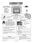
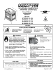
CASTILE PELLET STOVE
Owner’s Manual
Tested and
Listed by
C
Installation and Operation
Portland
Oregon USA
O-T L
US
OMNI-Test Laboratories, Inc.
Model:
CASTILE-MBK1
CASTILE-PMH1
CASTILE-CSB
CASTILE-CWL
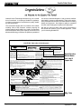
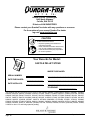
CAUTION
DO NOT DISCARD THIS MANUAL
• Important operating and • Read, understand and
follow these instrucmaintenance instructions for safe installations included.
tion and operation.
WARNING
• Leave this manual with
party responsible for use
and operation.
DO
DI
N
SC OT
AR
D
WARNING
Please read this entire manual
before installation and use of this
pellet fuel-burning room heater.
Failure to follow these instructions
could result in property damage,
bodily injury or even death.
HOT! DO NOT TOUCH.
SEVERE BURNS MAY RESULT.
CLOTHING IGNITION MAY RESULT.
Glass and other surfaces are hot
during operation and cool down.
• Keep children away.
• Do not store or use gasoline or other flammable vapors and liquids in the vicinity of this
or any other appliance.
• Do not overfire - If any external part starts to
glow, you are overfiring. Reduce feed rate.
Overfiring will void your warranty.
• Comply with all minimum clearances to combustibles as specified. Failure to comply may
cause house fire.
• CAREFULLY SUPERVISE children in same room as
appliance.
• Alert children and adults to hazards of high
temperatures.
• Do NOT operate with protective barriers open or
removed.
• Keep clothing, furniture, draperies and other
combustibles away.
CAUTION
CAUTION
Tested and approved for wood pellets and shelled
field corn fuel only. Burning of any other type of fuel
voids your warranty.
www.quadrafire.com
Check building codes prior to installation.
• Installation MUST comply with local, regional, state
and national codes and regulations.
• Consult local building, fire officials or authorities having
jurisdiction about restrictions, installation inspection,
and permits.
250-6422E
September 1, 2008
R
Castile Pellet Stove
our stoves, inserts and fireplaces. And yet we are old-fashioned when it comes to craftsmanship. Each unit is meticulously fabricated and surfaces are hand-finished for lasting
beauty and enjoyment. Our pledge to quality is completed
as each model undergoes a quality control inspection.
Hearth & Home Technologies welcomes you to our tradition of excellence! In choosing a Quadra-Fire appliance,
you have our assurance of commitment to quality, durability, and performance.
This commitment begins with our research of the market,
including ‘Voice of the Customer’ contacts, ensuring we
make products that will satisfy your needs. Our Research
and Development facility then employs the world’s most
advanced technology to achieve the optimum operation of
We wish you and your family many years of enjoyment in
the warmth and comfort of your hearth appliance. Thank
you for choosing Quadra-Fire.
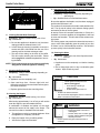
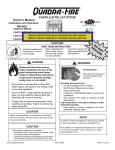
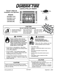
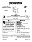
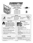
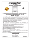
SAMPLE OF CLEARANCE TO COMBUSTIBLES LABEL
LOCATION: Back side of left side panel.
Portland
Oregon USA
O-T L
SERIAL NO. / NUMÉRO DU
R
Report / Rapport
061-S-33-2
US
C
OMNI-Test Laboratories, Inc.
Castile Pellet Stove
Listed Solid Fuel Room Heater/Pellet Type Insert. Also suitable for Mobile Home Installation. This appliance has
been tested and listed for use in Manufactured Homes in accordance with OAR 814-23-9000 through 814-23-909.
Appareil de chauffage inséré de combustible solide/de type de boulettes. Accepté dans l'installation dans les maisons mobiles. Cet
appareil a été testé et enregistré pour l'usage dans les Maisons Mobiles en accord avec OAR 814-23-9000 jusqu'à 814-23-909.
Tested to: ASTM E1509-95, ULC S627-00, ULC/ORD-C-1482-M1990 Room Heating Pellet Burning Type,
(UM) 84-HUD FOR USE ONLY WITH PELLETIZED WOOD OR SHELLED FIELD CORN FUEL.
Input Rating: 30,000 Btu's/hr
Electrical Rating: 115 VAC, 60 Hz, Start 4.1 Amps, Run 1.1 AMPS.
Route power cord away from unit. Do not route cord under or in front of appliance.
DANGER: Risk of electrical shock. Disconnect power supply before servicing. Replace glass only with 5mm
ceramic available from your dealer. To start, set thermostat above room temperature, the stove will light
automatically. To shutdown, set thermostat to below room temperature. For further instruction refer to owner's
manual.Keep viewing and ash removal doors tightly closed during operation.
DO NOT CONNECT THIS UNIT TO A CHIMNEY SERVING ANOTHER APPLIANCE.
Use a 3" or 4" diameter type "L" or "PL" venting system.
PRÉVENTION DES FEUX DE MAISON
Installez et utilisez en accord avec les instructions d'installation et d'opération du fabricant. Contactez le bureau de la
construction ou le bureau des incendies au sujet des restrictions et des inspections d'installation dans votre voisinage. Ne
pas obstruez l'espace en dessous de l'appareil.
AVIS - Pour Les Maisons Mobiles: Ne pas installer dans une chambre à coucher. Un tuyau extérieur de combustion d'air
doit être installé et ne doit pas être obstrué lorsque l'appareil est en usage. La structure intégrale du plancher, du plafond et
des murs de la maison mobile doit être maintenue intacte.
Référez vous aux instructions du fabricant et des codes locaux pour les précautions requises pour passer une cheminée à
travers un mur ou un plafond combustibles, et les compensations maximums.
Inspectez et nettoyez la cheminée fréquemment. Ne pas connecter cet appareil à une cheminée servant un autre appareil.
Utilisez systèm de ventilation "L" ou "P" diamètre 76mm ou 102mm.
PL
PREVENT HOUSE FIRES
Install and use only in accordance with manufacturer's installation and operating instructions. Contact local
building or fire officials about restrictions and inspection in our area.
WARNING - FOR MOBILE HOMES: Do not install appliance in a sleeping room. An outside combustion air
inlet must be provided. The structural integrity of the mobile home floor, ceiling and walls must be maintained.
Refer to manufacturer's instructions and local codes for precautions required for passing chimney through a
combustible wall or ceiling. Inspect and clean vent system frequently in accordance with manufacturer's
instructions.
Testé à: ASTM #1509-95, ULC S627-00 ULC/ORD-C 1482-M1990 Room Heating. Pellet Burning Type, (UM) 84-HUD
POUR USAGE AVEC LES BOULETTES DE BOIS OU DE COMBUSTIBLE DE MAIS ÉCOSSÉ DES CHAMPS.
Puissance de Rendement: 30,000 Btu's/hr
Puissance Électrique: 115 VAC, 60 Hz, Début 4.1 Amps, Courir 1.1 Amps,
Éloignez le fil électrique de l'appareil. Ne pas faire passer le fil électrique au dessus ou en dessous de l'appareil.
DANGER: Il y a risque de décharge électrique. Déconnectez le fil électrique de la prise de contact avant le service.
Remplacez la vitre seulement avec une vitre céramique de 5 mm disponible chez votre fournisseur.
Pour allumer, monter la température du thermostat au dessus de la température de la pièce, le poêle s'allumera
automatiquement. Pour éteindre, descendre la température du thermostat en dessous de la température de la pièce. Pour des
instructions supplémentaires, référez vous au manuel du propriétaire. Gardez la porte d'ouverture et la porte des cendres
fermées hermétiquement durant l'opération.
Serial Number
Model Name
Test Lab &
Report No.
E
Tested and
Listed by
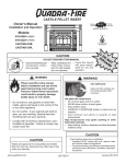
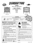
MINIMUM CLEARANCES TO COMBUSTIBLE MATERIALS / ESPACES LIBRES MINIMUM DES MATÉRIAUX COMBUSTIBLES:
A
D
C
F
B
E
C
F
"E" is to Cast Top
("E" du haut)
M
"B" is to Cast Top
("B" du haut)
A
B
Note 1: In residential installations, when using Parts 811-0890, (3" - 3" Top Vent Adapter) and 812-3570 (3" - 6" Offset
Adapter), 24 gauge 6" single wall flue connector may be used.
SA
Note 1: Dans les installations résidentielles, lorsque les pièces 811-0890, (dessus de l'adapteur de ventilation 3" - 3") et
812-3570 (le ressaut de l'adapteur 3" - 6"), un tuyau connecteur de 6" pour mur simple de calibre 24 peut être utilisé.
Note 2: In manufactured home installation, when using Part 811-0890, (3" - 3" Top Vent Adapter) and 812-3570 (3' - 6"
Offset Adapter), use listed double wall flue connector. An Outside Air Kit (Part 811-0872), must be used with manufactured
home installation.
Note 2: Pour l'installation dans les maisons préfabriquées, lorsque les pièces 811-0860, (dessus de l'adapteur de
Back Wall to stove / Mur Arrière du poêle
Side Wall to Cast Top / Mur De Côté du haut
2"/51mm
6"/152mm
CORNER INSTALLATION / NSTALLATION DU COIN :
C
Side Wall / Mur De Côté
2"/51mm
VERTICAL 3" - 6" ADAPTER KIT (PART 812-3570) INSTALLATION:
UN ASSEMBLAGE POUR ADAPTEUR 3" - 6" (PIÈCE 812-3570) POUR INSTALLATION VERTICALE:
D
Back Wall to Flue Pipe / Mur Arrière tuyau rigide
3"/76mm
E
Side Wall to Cast Top / Mur De Côté du haut
6"/152mm
CORNER INSTALLATION WITH VERTICAL ADAPTER KIT:
INSTALLATION DU COIN AVEC UN ASSEMBLAGE D'ADAPTEUR VERTICAL:
F
Side Wall / Mur De Côté
2"/51mm
ALCOVE INSTALLATION / INSTALLATION DE L' ALCÔVE:
Min. Alcove Height: / Une hauteur minimum de l'alcôve
Min. Alcove Side Wall: / Une hauteur minimum mur de côté de l'alcôve
Max. Alcove Depth: / La profondeur maximum de l'alcôve
43"/1092mm
6"/152mm
36"/914mm
ventilation 3" - 3") et 812-3570 (le ressaut de l'adapteur 3" - 6"), utilisez un tuyau connecteur enregistré pour mur double.
Un assemblage d'air extérieur (pièce 811-0872), doit être utilisé pour l'installation dans les maisons préfabriquées.
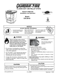
FLOOR PROTECTION / PROTECTION DU SOL
H*
G
G
I
G = 2"/51mm
H* = 2"/51mm
I = 6"/152mm
*Non-combustible floor protection must extend beneath the flue pipe when installed with
horizontal venting or under the Top Vent Adapter with vertical installation.
RECOMMENDED IN USA; REQUIRED IN CANADA
Floor protector must be noncombustible material, extending beneath heater and to the
front/sides/rear as indicated. Measure front distance (I) from the surface of the glass
door.
Mfg by:Fabriqué par:
U.S. ENVIRONMENTAL PROTECTION AGENCY This model is exempt from EPA certification under 40 CFR 60.531 by definition [Wood Heater (A) "Air-to-Fuel Ratio"].
2008 2009 2010 Jan.
1445 Highway North
Colville, WA 99114
Page 2
*Un protecteur incombustible de plancher doit s'étendre sous le conduit de cheminée
pour une installation de ventilation horizontale ou sous un adapteur de ventilation de
dessus pour une installation verticale. ÉTATS-UNIS - RECOMMANDÉ; CANADA REQUIRENT
Le poêle doit être placé sur une assise non combustible s’étendant tout autour de lui, comme les
schémas l’indiquent. Mesurez la distance du devant (I) de la surface de la porte vitrée.
Feb.
Mar. Apr.
May June
DO NOT REMOVE THIS LABEL / NE PAS ENLEVER L'ÉTIQUETTE
July Aug. Sept.
Oct. Nov.
Made in U.S.A./Fait Aux États-Unis
250-6422E
Dec.
250-6411
Mfg. Date
September 1, 2008
R
Castile Pellet Stove
TABLE OF CONTENTS
Section 1: Listing and Code Approvals
A.
B.
C.
D.
E.
Appliance Certifications ......................4
Mobile Home Approved ......................4
Glass Specifications ............................4
Electrical Rating ..................................4
BTU & Efficiency Specifications ..........4
Section 9: Troubleshooting ............................24-26
Section 10: Maintaining & Servicing Appliance
A. Proper Shutdown Procedures ...............27
B. General Maintenance & Cleaning .......27-29
C. High Ash Fuel Content Maintenance ..30
D. Blower Replacement ...........................31
E. Igniter Replacement ............................32
F. Baffle Removal ....................................32
G. Glass Replacement .............................33
Section 2: Getting Started
A. Design, Installation & Location
Considerations ....................................5
B. Fire Safety ..........................................5
C. Tools & Supplies Needed ...................6
D. Inspect Appliance & Components.......6
Section 12: Reference Material
A.
B.
C.
D.
E.
F.
G.
H.
Section 3: Dimensions & Clearances
A. Appliance Dimensions ........................7
B. Clearances to Combustibles ...............8
C. Hearth Requirements..........................9
Section 4: Vent Information
A.
B.
C.
D.
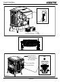
Component Functions.........................34-35
Component Locations .........................36
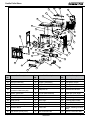
Exploded Drawings .............................37-38
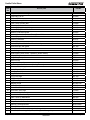
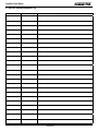
Service Parts & Accessories ...............40-42
Service & Maintenance Log ................43-44
Homeowner’s Notes ............................45
Warranty Policy ...................................46-47
Contact Information .............................48
Chimney & Exhaust Connection .........10
Venting Termination Requirements ....10
Equivalent Feet of Pipe .......................11
Pipe Selection Chart ............................11
Section 5: Venting Systems
A.
B.
C.
D.
E.
F.
Alcove .................................................12
Through the Wall .................................13
Vertical ................................................14
Through the Wall & Vertical ................14
Masonry ..............................................15
Alternate Masonry ...............................15
Section 6: Mobile Home ..................................16
Section 7: Appliance Set-Up
A.
B.
C.
D.
E.
F.
Outside Air Kit .....................................17
Leg Leveling System ...........................18
Top Vent Adapter ................................18
Rear Vent Adapter ..............................18
Log Set Placement ..............................19
Thermostat Installation ........................20
Section 8: Operating Instructions
A.
B.
C.
D.
E.
F.
G.
H.
Fuel Size & Material ............................21
General Operation Information ...........21
Before Your First Fire .........................22
Starting Your First Fire........................22
Fire Characteristics .............................22
Feed Rate Adjustment Instructions.....22
Ignition Cycles ....................................23
Frequently Asked Questions...............22
September 1, 2008
250-6422E
Page 3
R
Castile Pellet Stove
1
Listing and Code Approvals
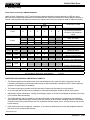
E. BTU & Efficiency Specifications
A. Appliance Certification
Model:
Castile Pellet Stove
Laboratory:
OMNI Test Laboratories, Inc.
Particulate Emissions Rating:
.7 grams/hr
Report No.
061-S-33-2
*BTU Output:
8,000 - 30,000 / hr
Type:
Solid Fuel Room Heater/Pellet Fuel Burning Type
Heating Capacity:
up to 1,500 sq. ft. depending
on climate zone
Standard:
ASTM E1509-95, ULC S627-00 and ULC/
ORD-C1482-M1990 Room Heater Pellet
Fuel Burning type and (UM) 84-HUD,
Mobile Home Approved.
Hopper Capacity:
40 lbs
Fuel:
Wood Pellets or Shelled Corn
Shipping Weight:
258 lbs
State Listing:
*BTU output will vary, depending on the brand of fuel you
use in your stove. Consult your Quadra-Fire dealer for
best results.
State of Colorado
B. Mobile Home Approved
This appliance is approved for mobile home installations
when not installed in a sleeping room and when an outside
combustion air inlet is provided. The structural integrity of
the mobile home floor, ceiling, and walls must be maintained.
The appliance must be properly grounded to the frame of
the mobile home and use only listed pellet vent Class “L” or
“PL” connector pipe. A Quadra-Fire Outside Air Kit must be
installed in a mobile home installation.
NOTE: Hearth & Home Technologies, manufacturer of
this appliance, reserves the right to alter its products,
their specifications and/or price without notice.
C. Glass Specifications
This appliance is equipped with 5mm ceramic glass. Replace
glass only with 5mm ceramic glass. Please contact your
dealer for replacement glass.
NOTE: This installation must conform with local codes.
In the absence of local codes you must comply with the
ASTM E1509-95, ULC S627-00 ULC/ORD-C-1482M1990 (UM) 84-HUD
D. Electrical Rating
115 VAC, 60 Hz, Start 4.1 Amps, Run 1.1 Amps
Page 4
250-6422E
September 1, 2008
R
Castile Pellet Stove
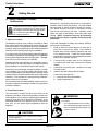
2
Getting Started
A. Design, Installation & Location
Considerations
B. Fire Safety
Maintain the designated clearances to combustibles.
Insulation must not touch the chimney. You must maintain
the designated air space clearance around the chimney.
This space around a chimney is necessary to allow
natural heat removal from the area. Insulation in this
space will cause a heat buildup, which may ignite wood
framing. NOTE: Clearances may only be reduced by
means approved by the regulatory authority having
jurisdiction.
Installation and service of this appliance should be
performed by qualified personnel. Hearth & Home
Technologies recommends NFI certified professionals, or technicians supervised by an
NFI certified professional.
1. Appliance Location
Consideration must be given to safety, convenience, traffic
flow, and the fact that the appliance will need a chimney and
chimney connector. It is a good idea to plan your installation
on paper, using exact measurements for clearances and floor
protection, before actually beginning the installation.
If you are not using an existing chimney, place the appliance
in a location to maintain a clear passage for the installation
of any listed and approved pellet venting system. This appliance may be vented vertically or horizontally.
Maintain specified vent clearance to comubstible requirements listed by the pellet manufactures venting instructions
and all clearance to combustivles listed in this manual.
Check with your local building code agency before you begin
your installation. Be sure local building codes do not supersede UL specifications and always obtain a building permit
so that insurance protection benefits cannot be unexpectedly
cancelled. If any assistance is required during installation,
please contact your local dealer.
To provide reasonable fire safety, the following should be
given serious consideration:
1.
Install at least one smoke detector on each floor of
your home to ensure your safety. They should be
located away from the heating appliance and close
to the sleeping areas. Follow the smoke detector
manufacturer’s placement and installation instructions,
and be sure to maintain regularly.
2.
A conveniently located Class A fire extinguisher
to contend with small fires resulting from burning
embers.
3.
A practiced evacuation plan, consisting of at least
2 escape routes.
4.
A plan to deal with a hopper fire as follows:
In the event of a hopper fire:
a.
b.
Evacuate the house immediately.
Notify fire department.
We recommend that a qualified building inspector and your
insurance company representative review your plans before
and after installation.
2. Thermostat Location
The thermostat’s location will have some effect on the
appliance’s operation. When the thermostat is located close
to the appliance, it may require a slightly higher temperature
setting to keep the rest of the house comfortable. If the
thermostat location is in an adjacent room or on a different
floor level, you will notice higher temperatures near the
appliance.
WARNING
Fire Hazard.
•
Do not operate appliance before reading
and understanding operating instructions.
•
Failure to operate appliance properly may
cause a house fire.
CAUTION
• Do NOT connect this unit to a chimney flue servicing
another appliance.
• Do NOT connect to any air distributon duct or system.
September 1, 2008
250-6422E
Page 5
R
Castile Pellet Stove
D. Inspect Appliance & Components and
Pre-Use Check List
C. Tools And Supplies Needed
Tools and building supplies normally required
for installation, unless installing into an existing
masonry fireplace:
Reciprocating Saw
Safety Glasses
Channel Locks
Framing Square
Hammer
Electric Drill & Bits (1/4”)
Phillips Screwdriver
1/4” Self-Tapping Screws
Tape Meausre
Plumb Line
May also need:
Level
Vent Support Straps
Framing Material
Venting Paint
Hi-temp Caulking Material
Gloves
1.
Place the appliance in a location near the
final installation area and follow the procedures below:
2.
Open the appliance and remove all the parts
and articles packed inside the Component
Pack. Inspect all the parts and glass for shipping damage. Contact your dealer if any irregularities are noticed.
3.
All safety warnings have been read and followed.
4.
This Owner’s Manual has been read.
5.
Floor protection requirements have been met.
6.
Venting is properly installed.
7.
The proper clearances from the appliance and
chimney to combustible materials have been
met.
8.
The masonry chimney is inspected by a professional and is clean, or the factory built metal
chimney is installed according to the manufacturer’s instructions and clearances.
9.
The chimney meets the required minimum
height.
10.
All labels have been removed from the glass
door.
11.
Plated surfaces have been wiped clean, if
applicable.
12.
Thermostat or remote has been installed.
13.
A power outlet is available nearby.
WARNING
Inspect appliance and components for
damage. Damaged parts may impair safe
operation.
• Do NOT install damaged components.
• Do NOT install incomplete components.
• Do NOT install substitute components.
Report damaged parts to dealer.
WARNING
Fire Risk.
Hearth & Home Technologies disclaims any
responsibility for, and the warranty will be
voided by, the following actions:
• Installation and use of any damaged appliance.
• Modification of the appliance.
• Installation other than as instructed by Hearth & Home
Technologies.
• Installation and/or use of any component part not approved
by Hearth & Home Technologies.
• Operating appliance without fully assembling all
components.
• Operating appliance without legs attached (if supplied with
unit).
• Do NOT Overfire
Or any such action that may cause a fire hazard.
Page 6
250-6422E
September 1, 2008
R
Castile Pellet Stove
3
Dimensions and Clearances
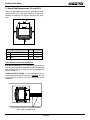
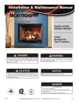
A. Appliance Dimensions
23-5/8 in.
(651mm)
11-13/16 in.
(300mm)
28-7/16 in.
(722mm)
24-3/4 in.
(629mm)
23-1/4 in.
(591mm)
Figure 7.2- Front View
Figure 7.1 - Top View
30-5/16 in. (770mm)
27-15/16 in. (710mm)
22-15/16 in.
(583mm)
4-1/4 in.
(107mm)
3 in. (76mm)
CL
28-5/16 in.
(718mm)
CL
16-1/16 in.
(408mm)
15-13/16 in.
(402mm)
Figure 7.3 -Side View
September 1, 2008
16-5/16 in.
(414mm)
Figure 7.4 - Side View with Top Vent Adapter
250-6422E
Page 7
R
Castile Pellet Stove
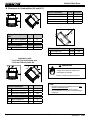
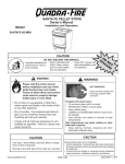
B. Clearances to Combustibles (UL and ULC)
Inches
Millimeters
Minimum Alcove Height
43
1092
Minimum Alcove Side Wall
6
152
Minimum Alcove Width
38
965
Maximum Alcove Depth
36
914
Alcove Installation
A
C
B
C
I
J
Straight Back Against
Wall
A Back Wall to Appliance
B Side Wall to Appliance
Inches
Millimeters
2
51
6
152
Corner Installation
C Walls to Appliance
Inches
Millimeters
2
51
CL
Dimension to Corner
I Flue Center Line
J Back of Top Vent Adapter
Inches
Millimeters
10-3/8
264
9-1/8
232
Installations with:
3 to 3 inch Top Vent Adapter and
3 to 6 inch Offset Adapter Kit
F
D
WARNING
H
G
Fire Risk.
Comply with all minimum clearances to
combustibles as specified.
H
E
Failure to comply may cause house fire.
G
Vertical Installation
D Back Wall to Flue Pipe
Side Wall to Cast Top
E
Back Wall to Appliance
F
Inches
Millimeters
3
76
6
152
8
203
Corner Installation
G Walls to Appliance
H Side Wall to Flue Pipe
Inches
Millimeters
2
51
3
76
Page 8
NOTE:
• Illustrations reflect typical installations and are FOR
DESIGN PURPOSES ONLY.
• Illustrations/diagrams are not drawn to scale.
• Actual installation may vary due to individual design
preference.
250-6422E
September 1, 2008
R
Castile Pellet Stove
C. Hearth Pad Requirements (UL and ULC)
Use a non-combustible floor protector, extending beneath
appliance and to the front, sides and rear as indicated.
Measure front distance “M” from the surface of the glass
door.
L*
K
K
M
Hearth Pad Requirements
K Sides
L* Back
M Front
Inches
Millimeters
2
51
2
51
6
152
*L Exception for Horizontal Installations:
USA INSTALLATIONS: A non-combustible floor protection is
recommended extending beneath the flue pipe when installed
with horizontal venting or under the Top Vent Adapter with
vertical installation.
CANADA INSTALLATIONS: A non-combustible floor protection extending beneath the flue pipe is required with horizontal venting or under the Top Vent Adapter with vertical
installation.
Must extend 2 inches (51mm) beyond each
side of pipe (shaded area)
September 1, 2008
250-6422E
Page 9
R
Castile Pellet Stove
4
Vent Information
B. Venting Termination Requirements
A. Chimney and Exhaust Connection
1. Chimney & Connector: Use 3 or 4 inch (76-102mm)
diameter type "L" or "PL" venting system. It can be
vented vertically or horizontally.
2. Mobile Home: Approved for all listed pellet vent. If
using the 3 inch (76mm) vertical Top Vent Adapter Kit
or the 3 to 6 inch (76-152mm) Top Vent Offset Adapter,
use listed double wall flue connector. A Quadra-Fire
Outside Air Kit must be used with manufactured home
installations.
CAUTION
Do not terminate vent in any enclosed or semi-enclosed
area such as a carport, garage, attic, crawl space, under a
sun deck or porch, narrow walkway or closely fenced area,
or any location that can build up a concentration of fumes
such as a stairwell, covered breezeway, etc.
1. Termination must exhaust above air inlet elevation. It is
recommended that at least 60 inches (1524mm) of vertical pipe be installed when appliance is vented directly
through a wall. This will create a natural draft, which will
help prevent the possibility of smoke or odor venting into
the home during a power outage. It will also keep exhaust
from causing a nuisance or hazard by exposing people or
shrubs to high temperatures. The safest and preferred
venting method is to extend the vent vertically through the
roof.
3. Residential: The 3 inch (76mm) vertical Top Vent
Adapter Kit and the 3 to 6 inch (76-152mm) Top Vent
Offset Adapter are tested to use 24 gauge single wall
flue connector or listed double wall flue connector to
Class A listed metal chimneys, or masonry chimneys
meeting ICBO standards for solid fuel appliances.
4. INSTALL VENT AT CLEARANCES SPECIFIED BY THE
VENT MANUFACTURER.
5. Secure exhaust venting system to the appliance with at
least 3 screws. Also secure all connector pipe joints with
at least 3 screws through each joint.
NOTE: All pipe must be welded seam pipe whenever
possible. Seal pipe joints with high temperature silicone
(500°F [260°C] minimum rated only).
NOTE: If burning shelled field corn, you must use
approved venting specifically designed for corn. Follow
the instructions from the venting manufacturer.
a. Not less than 48 inches (1219mm) below;
b. Not less than 48 inches (1219mm) horizontally from;
c. Not less than 12 inches (305mm) above.
3. Distance from permanently closed windows:
a. Not less than 12 inches (305mm) below, horizontally
from or above.
4. Distance between bottom of termination and grade should
be 12 inches (305mm) minimum. This is conditional upon
plants in the area, and nature of grade surface. The grade
surface must be a noncombustible material (i.e., rock, dirt).
The grade surface must not be lawn. Distance between
bottom of termination and public walkway should be 84
inches (2134mm) minimum.
5
WARNING
Fire Hazard.
• Only LISTED venting components may be
used.
Distance to combustible materials must be 24 inches
(610mm) minimum. This includes adjacent buildings,
fences, protruding parts of the structure, roof overhang,
plants and shrubs, etc.
6. Termination Cap Location (Home Electrical Service)
• NO OTHER vent components may be used.
Substitute or damaged vent components may
impair safe operation.
WARNING
Vent surfaces get HOT, can cause burns if
touched. Noncombustible shielding or guards
may be required
Page 10
2. Distance from doors and opening windows, or gravity or
ventilation air inlets into building:
•
Side-to-side clearance is to be the same as minimum
clearance to vinyl inside corners.
•
Clearance of a termination cap below electrical service
shall be the same as minimum clearance to vinyl soffits.
•
Clearance of a termination cap above electrical service
will be 12 inches minimum.
•
Location of the vent termination must not obstruct or
interfere with access to the electrical service.
250-6422E
September 1, 2008
R
Castile Pellet Stove
WARNING
C. Equivalent Feet of Pipe
The table below can help you calculate the equivalent feet
of pipe which is a method used to determine pellet vent size.
See Figure 11.1
Improper installation, adjustment, alteration, service or
maintenance can cause injury or property damage. Refer
to the owner’s information manual provided with this appliance. For assistance or additional information consult a
qualified installer, service agency or your dealer.
Example of 3 Elbow-Rear Vent Termination Calculaton
2 ft.
Pellet Venting
Component
# of
Elbows
90o Elbow or Tee
3
Feet of
Pipe
Multipled
By
Equivalent
Feet
Equivalent Feet
X
5
15
X
3
45o Elbow
3 ft.
Horizontal Pipe
7
X
1
Vertical Pipe
2
X
0.5
Components
7
1
Total Equivalent Feet
23
2 ft.
Note: This is a generic example and is not
intended to represent any specific fuel type.
2 ft.
Figure 11.1
D. Pipe Selection Chart
The chart will help you in determing proper venting size according to the equivalent feet of pipe
calcuated above and the altitude above sea level
of this installation. See Figure 11.2.
Locate the calculated equivalent feet of pipe on
the vertical left side of the chart. Move to the
right horizontally on the chart until you reach
your altitude above sea level.
30
September 1, 2008
) Dia eter Pipe Only
Example 1
20
E ui alent Pipe
Lengt In Feet
Example 2
If you fall below the diagonal line, 3 or 4 inch (76
to 102mm) pipe may be used. If it is anywhere
above the diagonal line, a 4 inch (102mm) diameter pipe is required.
The chart reveals that a 90° elbow is 5 times as
restrictive to the flow of exhaust gases under
positive pressure as 1 foot of horizontal pipe, and
a foot of horizontal pipe is twice as restrictive as
a foot of vertical pipe.
4 in. (102
10
3 in. or 4 in. (76
0
1
2
3
or 102
4
5
) Dia eter Pipe
6
7
8
10
ALTITUDE IN THOUSANDS OF FEET
Figure 11.2
250-6422E
Page 11
R
Castile Pellet Stove
5
Venting Systems
A. Alcove
A
C
D
B
Figure 12.1
Minimum
Inches
A
B
C
D
Maximum
Millimeters Inches Millimeters
Height
43
1092
n/a
n/a
Width
38
965
n/a
n/a
Depth
n/a
n/a
36
914
6
152
n/a
n/a
To Side Wall
All minimums listed are to a combustible surface.
NOTE:
• Illustrations reflect typical installations and are FOR
DESIGN PURPOSES ONLY.
• Illustrations/diagrams are not drawn to scale.
• Actual installation may vary due to individual design
preference.
Page 12
250-6422E
September 1, 2008
R
Castile Pellet Stove
B. Through The Wall
NOTE:
In Canada, where passage through a wall or partition of
combustible construction is desired, the installation shall
conform to CAN/CSA-B365
Horizontal termination cap must be a minimum of 12 inches.
(305mm) from the wall. Approved for mobile home installations. Must use 3 or 4 inch (76-102mm) “L” or “PL” listed
pellet venting or listed double wall pipe and a Quadra-Fire
Outside Air Kit in mobile homes.
2 in.
(51mm)
Minimum
Straight Out
6 in.
(152mm)
Minimum
From Glass
Wall
Thimble
Horizontal
Termination
Cap
12 in.
(305mm)
Minimum
Noncombustible Hearth Pad
Figure 13.1
45 Degree
Illustration shows venting going in both directions.
Choose which one is best for your installation.
12 in. (305mm)
Minimum
Wall
Thimble
2 in. (51mm)
Minimum
12 in.
(305mm)
Minimum
2 in.
(51mm)
Minimum
Figure 13.2
September 1, 2008
250-6422E
Page 13
R
Castile Pellet Stove
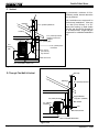
C. Vertical
We recommend a minimum of 60 in.
(1524mm) vertical, however above the
eave is preferred.
Rain Cap
Flashing
24 in. (610mm) Minimum
Firestop
Ceiling Support
6 in.
(152mm)
Min.
6 in. (152mm) Class A
Chimney Connector
Adapter
3 in. (76mm) Min.
Both installations are approved for
mobile home installations. Must use
3 or 4 inch (76 to 102mm) “L” or “PL”
listed pellet venting or listed double
wall pipe and Quadra-Fire Outside Air
Kit in mobile homes. Single wall pipe
is approved for residential installations
only.
6 in. (152mm) Flue
Connector
3 in. to 6 in.
(76-152mm)
Top Vent Kit
Clean-out Cover
Non-combustible Hearth Pad
Figure 14.1
D. Through The Wall & Vertical
Rain Cap
Flashing
24 in. (610mm) minimum
2 in. (51mm) minimum
6 in. (152mm)
minimum
Support Bracket
every 60 in. (1524mm)
Wall Thimble
Tee
Cleanout Cover
Non-combustible Hearth Pad
Figure 14.2
Page 14
250-6422E
September 1, 2008
R
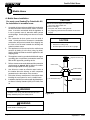
Castile Pellet Stove
WARNING
Fire Hazard
Inspection of Chimney:
• Masonry chimney must be in good condition.
• Meets minimum standard of NFPA 211
• Factory-built chimney must be 6 in. (152mm) UL103 HT.
E. Masonry
Fireclay flue
liner with airspace
Concrete Cap
Flashing
1 in. (25mm) clearance
with firestop
1 in. (25mm)
clearance
3 in. (76mm)
minimum
6 in. (152mm)
minimum
Sheathing
Cleanout cover
Airtight
Cleanout Door
Non-combustible Hearth Pad
Figure 15.1
F. Alternate Masonry
Concrete Cap
Fireclay Flue Liner
with airspace
Flashing
1 in. (25mm) clearance
with firestop
1 in. (25mm) clearance
2 in. (51mm) minimum
6 in. (152mm)
minimum
Sheathing
Airtight cleanout door
Noncombustible Hearth Pad
Figure 15.2
September 1, 2008
250-6422E
Page 15
R
Castile Pellet Stove
6
Mobile Home
A. Mobile Home Installation
You must use a Quadra-Fire Outside Air Kit
for installation in a mobile home.
1.
An outside air inlet must be provided for the combustion
air and must remain clear of leaves, debris, ice and/or
snow. It must be unrestricted while the appliance is
in use to prevent room air starvation which causes
smoke spillage. Smoke spillage can also set off smoke
alarms.
2.
The combustion air duct system must be made of
metal. It must permit zero clearance to combustible
construction and prevent material from dropping into
the inlet or into the area beneath the dwelling and
contain a rodent screen.
3.
The appliance must be secured to the mobile home
structure by bolting it to the floor (using lag bolts).
Use the same holes that secured the appliance to the
shipping pallet.
4.
The appliance must be grounded with #8 solid copper
grounding wire or equivalent, terminated at each end
with an NEC approved grounding device.
5.
Refer to clearances to combustibles and floor protection
requirements on pages 8 & 9 for listings to combustibles and appropriate chimney systems.
6.
Use silicone to create an effective vapor barrier at
the location where the chimney or other component
penetrates to the the exterior of the structure.
7.
Follow the chimney manufacturer’s instructions when
installing the vent system for use in a mobile home.
8.
Installation shall be in accordance with the Manufacturers Home & Safety Standard (HUD) CFR 3280, Part
24.
CAUTION
Maintain structural integrity of mobile home:
• Floor, wall, ceiling and/or roof.
Do NOT cut through:
• Floor joist, wall, studs or ceiling trusses.
• Any supporting material that would affect the structural
integrity.
CAUTION
Never draw outside combustion air from:
• Wall, floor or ceiling cavity
• Enclosed space such as an attic or garage
Spark Arrestor Cap
Storm Collar
Roof Flashing
Joist Shield/Firestop
Approved Class “L”
or “PL” Pellet Pipe
WARNING
Installation must comply with Manufactured Home and
Safety Standard (HUD), CFR 3280, Part 24.
Figure 16.1
WARNING
Never install in a sleeping room.
Page 16
250-6422E
September 1, 2008
R
Castile Pellet Stove
7
Appliance Set-Up
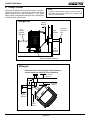
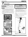
A. Outside Air Kit Instructions
CAUTION
Parts Included in Kit: 1 piece of 2 inch x 3 foot flex hose,
2 hose clamps, 1 collar assembly,1 termination cap assembly, 1 trim ring, 12 screws.
Tools Needed: Phillips headscrewdriver; wire cutters; hole
saw or jig saw.
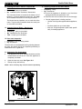
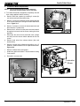
1. Figure 17.1 shows bottom of convection blower mount
and pre-cut air vent opening for reference only. Air channel should be mounted with stove in upright position.
2. Align hooks in air channel with slots in convection blower
mount and ash box, Figure 17.2. Push up and slide forward.
3. Secure air channel to appliance with 2 screws and secure
the collar assembly to the air channel with 2 screws.
Figure 17.3.
Never draw outside combustion air from:
• Wall, floor or ceiling cavity
• Enclosed space such as an attic or garage
1. Measure distance from floor to air vent opening in
appliance and mark location on wall.
Use saw to cut opening in wall. Cut a 2-1/2 to 3 inch
(64-76mm) opening on inside wall and a 3 to 3-1/2
inch (76-89mm) opening on outside of house.
2. Use hose clamp to secure flex pipe to collar assembly.
3. Slide trim ring over flex pipe and run pipe through
wall.
4. Attach hose to outside termination cap with second
hose clamp.
5. Secure termination cap to outside surface.
Mounting Slots
6. Secure trim ring to interior wall.
Termination
Cap Assembly
Pre-cut Hole
Figure 17.1
Hose Clamp
Trim Ring
Align hooks with slots, push up
and slide forward
Flex Hose
Figure 17.2
Attach air channel to stove with 2 screws
Air Intake
Channel
Hose Clamp
Collar Assembly
Attach collar to air channel with 2 screws
Figure 17.4
Figure 17.3
September 1, 2008
250-6422E
Page 17
R
Castile Pellet Stove
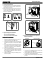
B. Leg Leveling System
Offset Collar
3 to 6 inch
1. Thread Allen bolts through nuts until flush. Figure 18.1.
The Allen bolts and nuts are included in the component
pack inside the stove firebox.
Rear Exhaust Outlet
2. Slide assembled nuts and bolts into slots on legs with
the nuts on the bottom. Figure 18.2. Use a 5/32 in.
(3.96mm) Allen wrench to adjust legs up and down to
desired level. Figure 18.3
Top Vent Adapter
3 to 3 inch
Use hole on each side
as drilling guide
Figure 18.4
Figure 18.1
Figure 18.2
Figure 18.3 - Bolt fully extended
Mount with
4 screws
C. Top Vent Adapter Installation
Clean-Out Cover
Figure 18.5
3 to 3 inch Top Vent Adapter
3 to 6 inch Top Vent Offset Adapter
D. Rear Vent and Rear Vent to Top Vent
Adapter Installation
Installing the Top Vent Adapter
1.
Put a layer of high temperature silicone on the 3 inch
(76mm) rearexhaust outlet. Figure 18.4
2.
Slide the top vent adapter onto the rear exhaust outlet
and adjust the assembly to a vertical position. Figure
18.4
3.
Rear Vent
Rear to Top Vent
Clean-Out Cover
Drill 4 holes with #26 drill bit (provided) into the back
of the appliance using the outer shield as a pattern
(make sure the assembly is vertical). Figure 18.4
Clean-Out Cover
4.
Install the 4 mounting screws.
Figure 18.6
5.
Drill 2 holes with #26 drill bit through the rear exhaust
outlet using the 2 holes already in the short horizontal
pipe in the top vent adapter as a guide. Install the 4
screws. Figure 18.5.
1.
Put a layer of high temperature silicone on the 3 inch
(76mm) exhaust outlet. Figure 18.4
2.
Slide the adapter onto the rear exhaust outlet and adjust
the assembly to the appropriate position.
3.
Install the vent pipe into the adapter (be sure to silicone
all joints)
6.
Install the vent pipe into the top vent adapter (be sure
to silicone all joints).
Page 18
250-6422E
Figure 18.7
September 1, 2008
R
Castile Pellet Stove
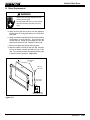
E. Optional Log Set Placement Instructions
CAUTION
Logs are FRAGILE. Use extreme care when handling or
cleaning logs.
4 PIECE LOG SET INSTALLATION
1. Open the hinged cast face and open the glass door
assembly.
2. To position the logs, place the right rear log as shown in
Figure 19.1. There is a notch in the bottom of the log for
clearance for the thermocouple and thermocouple cover
(ceramic protection tube).
Figure 19.3
3. Continue placing the last 3 logs around the firepot as
show in Figures 19.2, 19.3 and 19.4. Be careful not to
block the drop tube in the back of the firebox where pellets feed into the firepot.
Notch
Figure 19.4
Thermocouple
Cover
OPTIONAL TOP LOG
Place the log over the firepot. The
charred area on the back of the log is
turned toward the back, not the front.
Figure 19.1
The log will be about 2-1/2 inches
above the firepot when in place. It
must rest on the 3 logs in a stable
position to prevent it from falling into
the firepot.
Drop Tube
Figure 19.2
NOTE:
Due to the abrasive nature of a pellet appliance fire, the
logs are not covered under warranty. Any placement variation other than shown here can cause excessive heat and
shall void the appliance warranty.
September 1, 2008
250-6422E
Figure 19.5
Page 19
R
Castile Pellet Stove
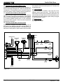
F. Thermostat Installation
1.
2.
A 12 volt AC thermostat is required to operate this pellet
appliance. You may use the included wall mount thermostat or purchase an optional programmable thermostat
or remote control. It is equipped with an adjustable
heat anticipator. The current rating is .05 amps. The
anticipator needs to be adjusted to the lowest setting
available.
When mounting a thermostat on a wall, be sure to follow
your thermostat installation instructions carefully.
CAUTION
Shock hazard.
• Do NOT remove grounding prong from plug.
• Plug directly into properly grounded 3 prong
receptacle.
• Route cord away from appliance.
• Do NOT route cord under or in front of appliance.
NOTE: Thermostat must be mounted level for
accurate readings. The thermostat should be
mounted on an inside wall and not in direct line
with the appliance convection air.
NOTE: If the thermostat is located too close to the
appliance, you may need to set the temperature
setting slightly higher to maintain the desired
temperature in your home.
3.
There is a 4 screw terminal block located on the back
lower right corner of the stove directly above the power
cord inlet. The center 2 screws are for the thermostat
wires.
FUSE
Fuse
TERMINAL BLOCK
CENTER 2 SCREWS FOR
THERMOSTAT WIRES
POWER OUTLET
Figure 20.1
Page 20
250-6422E
September 1, 2008
R
Castile Pellet Stove
8
Operating Instructions
B. General Operating Information
A. Fuel Size And Material
1. Wood Pellets
1. Thermostat Calls For Heat
Fuel pellets are made from sawdust or wood by-products. If the
source material is hardwood, they can have a higher mineral
content, creating more ash. Fuels containing bark will also have
higher ash content. Minerals and other noncombustible materials
such as sand will turn into a hard, glass-like substance called
a clinker when heated to the extreme temperatures our firepot
reaches. This is what forms clinkers in the bottom of the firepot.
Trees from different areas will vary in mineral content. That is
why some fuels produce more clinkers than others. Pellets are
manufactured in either 1/4 inch or 5/16 inch (6-8mm) diameter and
should be no more than 1-1/2 inches (38mm) in length. Pellet
lengths may even vary by lot from the same manufacturer which
is why the feed rate may need to be adjusted occasionally. If you
burn pellets longer than 1-1/2 inches (38mm) you may have
an inconsistent fuel feed rate and/or missed ignitions.
The appliance is like most modern furnaces; when the
thermostat calls for heat, your appliance will automatically
light and deliver heat. When the room is up to temperature
and the thermostat is satisfied, the red call light will go off
and the appliance will shut down.
Pellet fuel quality can greatly fluctuate. We recommend using
premium grade fuel with ash content less than 1%. Even in some
fuel labeled “premium” ash content can vary from bag to bag and
possibly exceed 1%. High ash fuel, or lack of maintenance, can
cause the firepot to fill up and thus create a potential for smoking,
sooting and possible hopper fires.
2. Heat Output Controls
This appliance is equipped with a heat output control
switch that has three settings or burn rates; low, medium
and high. The appliance will turn on and off as the
thermostat demands. When the thermostat calls for heat,
the appliance will start up at the burn rate for which it is
set. If the appliance is set at one of the lower settings, it
will run quieter but take longer to heat up an area than if it
were set at a higher burn rate. Regardless of the burn rate,
when the area is warm enough to satisfy the thermostat,
the appliance will shut off.
Heat Output Switch
Always burn dry fuel. Burning fuel with high moisture content takes
heat from the fuel and tends to cool the appliance, robbing heat
from your home. Damp pellet fuel can clog the feed system.
High
Med
Low
We recommend that you buy fuel in multi-ton lots whenever
possible. Buying large quantities of fuel at once will greatly
reduce the number of times the feed adjustments will need to be
made. However, we do recommend trying various brands before
purchasing multi-ton lots to ensure your satisfaction.
Reset
Button
WARNING
Reset Button
Fire and Smoke Risk.
•
•
Figure 21.1
High ash fuels or lack of maintenance
can cause firepot to overfill. Follow
proper shutdown procedure if ash buildup
exceeds haf way point in firepot.
WARNING
Failure to do so could result in smoking,
sooting and possible hopper fires.
2. Shelled Field Corn
Extensive factory and field testing has demonstrated shelled
field corn to be an efficient and very economical fuel. We
recommend the use of a 50-50 blend of corn and wood pellets.
The only change in operation is that the feed rate may require
a slight adjustment. The BTU output of the appliance varies
slightly compared to pellets, depending on the quality of the
corn used. In cases where it is acceptable for the appliance to
run full time, 100% corn will work after the fire has been started
using wood pellets.
September 1, 2008
•
•
•
•
250-6422E
Fire Hazard.
Keep combustible materials, gasoline
and other flammable vapors and liquids
clear of appliance.
Do NOT store flammable materials in the appliance’s
vicinity.
Do NOT use gasoline, lantern fuel, kerosene, charcoal
lighter fluid or similar liquids to start or “freshen up” a
fire in this heater.
Keep all such liquids well away from the heater while
it is in use.
Combustible materials may ignite.
Page 21
R
Castile Pellet Stove
C. Before Your First Fire
E. Fire Characteristics
1. First, make sure your appliance has been properly
installed and that all safety requirements have been met.
Pay particular attention to the fire protection, venting and
thermostat installation instructions.
A properly adjusted fire with the heat output control switch
set on “high” has a short active flame pattern that extends
out of the firepot approximately 4 inches (102mm). If the fire
has tall flames with black tails and seems somewhat lazy,
the feed rate will need to be reduced. This is done by sliding
the fuel adjustment control rod down, which will reduce the
feed. If the fire is not 4 inches (102mm) tall, slide the fuel
adjustment control rod up to increase the feed. A medium
and low setting will give a shorter flame. The flame will rise
and fall somewhat. This is normal.
2. Double check that the ash pan and firebox are empty!
3. Check the position of the thermocouple, located above
the firepot, and make sure that it protrudes approximately
3/4 inch (19mm) into the firepot. IMPORTANT DETAIL:
The tip of the thermocouple must be in contact with
the inside end of the thermocouple cover.
4. Close the front door.
F. Feed Rate Adjustment Instructions
D. Starting Your First Fire
The feed adjustment control rod is factory set, and should
be adequate for most fuels. However, if the flame height is
too high or too low, you will need to adjust the feed rate. Wait
until the appliance has been burning for 15 minutes before
making your adjustments and allow 15 minutes for feed
adjustment to take effect.
1. A thermostat is required for proper operation of this
appliance, except for corn. At this time, fill the hopper
with pellets, set the thermostat to its lowest setting. Plug
the power cord into nearby outlet.
2. The exhaust blower will stay on for approximately 18
minutes even though the thermostat is not calling for
heat. This is normal.
3. Locate the heat output control switch mounted on the back
of the appliance in the upper right corner. See Figure 21.1
on page 21. Turn it to the “high” setting by pushing the top
of the control switch in and then adjust the thermostat to
its highest setting. Open the right side panel and the red
call light located behind the control box will be on. See
Figure 22.1. This indicates the thermostat is calling for
heat.
1. Loosen the set screw 1/4 to 1/2 turn during set-up
of appliance. This will allow movement of the feed
adjustment control rod. Do not re-tighten set screw.
Figure 22.2.
2. Loosen the wing nut. Figure 22.3.
3. Adjust the feed adjustment control rod upward towards the
"+" symbol to increase the feed rate and flame height or
down towards the "-" symbol, to decrease the feed rate
and flame height. Figure 22.3.
4. Re-tighten the wing nut.
4. The fuel feed system and the igniter should now be on.
5. For your first fire it will be necessary to press the reset
button once approximately 2 minutes after start up and
again in 5 minutes. This will fill the feed system and allow
the appliance to begin dropping pellets. The appliance
will continue to run as long as the thermostat is calling
for heat.
Set Screw
6. Once the appliance has ignited, let it burn for approximately
15 minutes, then set the thermostat to the desired room
temperature. Adjust the heat output control switch to the
desired setting.
De
Fuel Adjustment
Control Rod
cr
ea
se
In
Red Call Light is
located on top of
Junction Box behind
the Control Box.
cr
ea
se
Figure 22.2
Wing Nut
Control
Box
Figure 22.3
Figure 22.1
Page 22
250-6422E
September 1, 2008
R
Castile Pellet Stove
G Iginition Cycles
WARNING
1. During each ignition cycle, it is normal to see some
smoke in the firebox. The smoke will stop once the
fire starts.
Fire Risk
Do NOT operate appliance:
• With appliance door open.
• Firepot floor open.
• Cleaning slide plates open.
Do NOT store fuel:
• Closer than required clearances to combustibles to appliance
• Within space required for loading or ash
removal.
2. The convection blower will automatically turn on after
your appliance has reached the set temperature on
the “high” setting. This blower transfers heat from your
appliance into the room, and will continue to run after
the thermostat has stopped calling for heat until the
appliance has cooled down.
3. Occasionally the appliance may run out of fuel and shut
itself down. When this happens, the red call light will
be on. (See Figure 22.1, page 22). To restart it, fill
the hopper and press the reset button. (See Figure
21.1, page 21). When you press the reset button the
red call light will go out. Release the button and the
light will come back on. You should see a fire shortly.
If not, follow the instructions on page 22, of “Starting
Your First Fire”.
CAUTION
Back side of Firepot
Odors and vapors released during initial operation.
• Curing of high temperature paint.
• Open windows for air circulation.
Odors may be irritating to sensitive individuals.
Firepot floor left open
Figure 23.1 - DO NOT LEAVE FIREPOT FLOOR OPEN
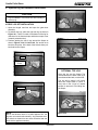
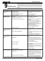
H. Frequently Asked Questions
ISSUES
SOLUTIONS
1. Metallic noise.
1. Noise is caused by metal expanding and contracting as
it heats up and cools down, similar to the sound produced by a furnace or heating duct. This noise does not
affect the operation or longevity of your appliance.
2.
Ash buildup on glass.
2. This is normal. Clean the glass.
3.
Glass has turned dirty.
3. Excessive build up of ash. The lower burn settings will
produce more ash, the higher burn settings produce
less. The more it burns on low the more frequent cleaning of the glass is required.
4.
Fire has tall flames with black tails and is lazy.
4. The feed rate needs to be reduced or the firepot needs
cleaning. Heat exchanger or exhaust blower needs
cleaning.
5.
Smokey start-up or puffs of smoke from the airwash. 5. Either the firepot is dirty or there is too much fuel at
start-up and not enough air. Close down feed rate 1/4
inch at a time until this no longer happens.
6.
Large flame at start-up.
September 1, 2008
6. This is normal. Flame will settle down once the fire is
established.
250-6422E
Page 23
R
Castile Pellet Stove
9
With proper installation, operation, and maintenance your appliance will provide years
of trouble-free service. If you do experience a problem, this troubleshooting guide
will assist a qualified service person in the diagnosis of a problem and the corrective
action to be taken. This troubleshooting guide can only be used by a qualified service
technician.
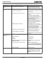
Troubleshooting
Possible Cause
Symption
Plug in appliance - No
response.
Call light on. No fire.
No fuel in firepot.
Call light on. No fire.
Partially burned fuel in
firepot.
Corrective Action
No current to outlet.
Check circuit breaker at service panel.
.7 amp fuse defective.
Replace fuse.
#3 snap disc tripped or defective.
Reset or replace snap disc.
Control box defective.
Replace control box.
Out of fuel.
Check hopper. Fill with fuel.
#2 snap disc may be defective.
Replace snap disc.
Vacuum switch not closing, no vacuum.
Check exhaust blower is plugged in and
operating.
Check vacuum switch is plugged in.
Check vacuum hose is in good condition,
clear and connected at both ends.
Check thermocouple is in good condition
and plugged in properly.
Make sure venting system is clean.
Make sure front door is closed.
Control box defective.
Replace control box.
Firepot clean-out plate not closed.
Check that firepot clean-out plate is fully
closed.
Firepot is dirty (missed ignition).
Clean firepot. Make sure there is no clinker
in the firepot.
Clinkers may have to be broken up with
firepot scraper tool or other means.
Call light on. No fire.
Unburned pellets in
firepot.
Firepot clean-out plate not closed.
Check that firepot clean-out plate is fully
closed.
Firepot is dirty.
Clean firepot. Make sure there is not a
clinker in the firepot. Clinkers may have to
be pushed out of firepot with firepot scraper
tool or other means.
Ignition hole blocked.
Scrape with solid piece of wire.
Remove ash pan to see if igniter is glowing
red on start-up.
Check igniter wires for good connection.
Replace igniter using 1/4 inch male /female
spade connectors.
Igniter not working.
Slow or smoky start-up.
Page 24
Control box defective.
Replace control box.
Firepot clean-out plate not closed.
Check that firepot clean-out is fully closed.
Firepot is dirty.
Clean firepot. Make sure there is not a
clinker in the firepot. Clinkers may have to
pushed out of firepot with firepot scraper
tool or other means.
Excessive amount of fuel at start-up.
Reduce feed rate using feed rate adjustment control rod located inside hopper.
250-6422E
September 1, 2008
R
Castile Pellet Stove
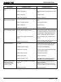
Symptom
Possible Cause
Corrective Action
Slow or smoky start-up
(Cont’d)
Dirty exhaust and/or venting system.
Check for ash build up in unit, including behind rear panels, firebox, heat
exchanger, exhaust blower and venting.
Feed system fails to
start.
Out of fuel.
Check hopper, fill with fuel.
#2 snap disc may be defective.
Replace snap disc. Firebox door must be
closed securely.
Vacuum switch not closing. No vacuum.
Check exhaust blower is plugged in and
operating.
Check vacuum switch is plugged in.
Check vacuum hose is in good condition,
clear and connected at both ends.
Check thermocouple is in good condition
and plugged in properly.
Make sure venting system is clean.
NOTE: High winds blowing into the venting system can pressurize the firebox
causing loss of vacuum.
Feed system jammed or blocked.
Empty hopper of fuel. Use a wet/dry
vacuum cleaner to remove remaining fuel,
from hopper, including feed tube.
Check feed chute for obstructions.
Loosen 2 feed assembly mounting screws
and lightly shake feed assembly.
Feed spring not turning with feed motor.
Feed motor defective or not plugged in.
Check that set screw is tight on feed
spring shaft at end of feed motor.
Check connections on feed motor, replace
if defective.
No call light. Unit
does not begin start
sequence.
Thermostat not set to a high enough temperature.
Adjust thermostat above room temperature.
Snap Disc #3 tripped.
Reset snap disc.
No power.
Connect to power.
Fuse blown.
Replace fuse.
Connections at thermostat and/or appliance not Check connections at thermostat and
making proper contact.
appliance.
Unit fails to shut off.
September 1, 2008
Defective thermostat or thermostat wiring.
Replace thermostat or wiring.
NOTE: To test thermostat and wiring, use
a jumper wire at the thermostat block on
the unit to by-pass thermostat and wiring.
Control box defective.
Replace control box.
Call light on.
Turn thermostat off.
If call light does not go out, disconnect
thermostat wires from unit. If call light
does go out, thermostat or wires are
defective.
250-6422E
Page 25
R
Castile Pellet Stove
Symptoms
Convection blower fails to
start.
Exhaust blower fails to
start or does not shut off.
Large, lazy flame, orange
color. Black ash on glass.
Nuisance shutdowns.
Appliance calls for heat.
Call light illuminates.
Exhaust blower starts.
No feed or igniter.
Page 26
Possible Cause
Corrective Action
#1 snap disc defective.
Replace snap disc.
Blower not plugged in.
Check that blower is plugged into wire harness.
Blower is defective.
Replace blower.
Control box is defective.
Replace control box.
Blower not plugged in.
Check that blower is plugged into wire harness.
Blower is clogged with ash.
Clean exhaust system.
Blower is defective.
Replace blower.
Control box is defective.
Replace control box.
Dirty appliance.
Poor fuel quality, high ash content.
Clean unit, including firepot, heat exchangers and venting system. Remove stainless
steel baffle from firebox to clean ash from
on top of baffle. Clean behind rear brick
panels. Change fuel brand to premium.
Firepot clean-out plate not completely
closed.
Check that firepot clean-out plate is fully
closed.
Excessive amount of fuel.
Reduce feed rate using feed rate adjustment
control rod located inside hopper.
Low flame.
Increase feed by opening feed rate adjustment control rod located inside hopper.
Sawdust buildup in hopper.
Clean hopper, see page 29.
Feed motor is reversing.
Check for good connections between feed
motor and wire harness.
Defective thermocouple.
Replace thermocouple.
Defective control box.
Replace control box.
Firepot more than 1/2 full.
See page 30 for detailed instructions for
“High Ash Fuel Content Management”
Thermocouple is defective or not properly
plugged in.
Check connections on thermocouple or
replace if defective.
A flashing yellow light on the control box
indicates a problem with the thermocouple.
Defective control box.
Replace control box.
250-6422E
September 1, 2008
R
Castile Pellet Stove
10
Maintaining & Servicing Your Appliance
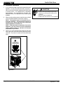
C. General Maintenance
1. Types of Fuel
A. Proper Shutdown Procedure
Depending on the type of fuel you are burning will dictate
how often you have to clean your firepot.
CAUTION
If the fuel you are burning has a high dirt or ash content
or you are burning shelled field corn, it may be necessary
to clean the firepot more than once a day.
Shock and Smoke Hazard
• Turn down thermostat, let appliance completely
cool and exhaust blower must be off. Now you
can unplug appliance before servicing.
• Smoke spillage into room can occur if appliance
is not cool before unplugging.
• Risk of shock if appliance not unplugged before
servicing appliance.
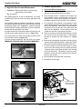
Dirty fuel will cause clinkers to form in the firepot. A clinker
is formed when dirt, ash or a non-burnable substance is
heated to 2000°F (1093°C) and becomes glass-like. See
“C” page 31 in this section for more details on fuels with
high ash content.
.
Clinker
Figure 27.1 - Clinker
B. Quick Reference Maintenance Chart
Cleaning or Inspection
Frequency
Daily Weekly Monthly
Yearly
Ash Pan
Every 5 bags of fuel
OR
X
Ash Removal from Firebox
More frequently depending on
the fuel type or ash build-up
OR
X
Beneath Heat Exchanger
Every 1 ton of fuel
OR
Blower, Combustion (Exhaust)
More frequently depending on
the fuel type
OR
X
Blower, Convection
More frequently depending on
the fuel type
OR
X
Door Latch Inspection
Prior to heating season
OR
Exhaust Path
More frequently depending on
ash build-up
OR
X
Firebox - Prepare for Non-Burn Season
At end of heating season
OR
X
Firepot - Burning pellets
Every 3 bags
OR
X
Firepot - Burning Corn
Every 1 bag
OR
X
Glass
When clear view of firepot
becomes obscure
OR
Heat Exchanger & Drop Tube
Every 1 ton of fuel
OR
X
Hopper
Every 1 ton of fuel or when
changing fuel types
OR
X
Top Vent Adapter
More frequently depending on
the fuel type or ash build-up
OR
X
Venting System
More frequently depending on
the fuel type
OR
X
September 1, 2008
250-6422E
X
X
X
Page 27
R
Castile Pellet Stove
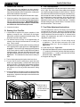
4. Cleaning Ash Pan
2. Cleaning Firepot with Cleaning Rod & Firepot
Scraper
•
•
•
•
Frequency: Daily or more often as needed
By: Homeowner
Frequency: Weekly or every 5 bags of fuel
By: Homeowner
Locate the ash pan underneath the firepot. Open the
bottom ash door and slide the ash pan straight out.
Empty into a non-combustible container and re-install
ash pan. See Disposal of Ashes.
a. The appliance must be in complete shutdown and cool
and the exhaust blower off. If you are just cleaning the
firepot, there is no need to unplug the appliance.
b. Pull firepot cleaning rod OUT a couple of times to help
shake debris loose. See Figure 37.2 on page 37. If rod
is hard to pull, it may be necessary to use your firepot
clean-out tool to chip away material that has built up
on the bottom plate of the firepot and to push out any
clinkers. Larger clinkers may have to be removed from
the top of the firepot. Corn clinkers can be especially
difficult to break up.
5. Disposal of Ashes
•
•
Frequency: As needed
By: Homeowner
Ashes should be placed in a metal container with a
tight-fitting lid. The closed container of ashes should
be placed on a non-combustible floor or on the ground,
well away from all combustible materials, pending final
disposal.
c. The firepot floor plate must be fully closed when
finished. See Figure 23.1 on page 23.
If the ashes are disposed of by burial in soil or otherwise
locally dispersed, they should be retained in the
closed container until all cinders have been thoroughly
cooled.
WARNING
7. Cleaning Heat Exchanger Chambers & Drop Tube
Fire Risk
•
•
• NEVER pull firepot cleaning rod or cleaning
slide plates out when appliance is operating.
• The cleaning slide plates must be fully
CLOSED when appliance is operating.
•. Hot pellets may fall into ashpan and start a fire
or mis-starts due to lack of vacuum.
Frequency: Monthly or every 1 ton of fuel
By: Homeowner
WARNING
3. Ash Removal from Firebox
•
•
Heat exchanger cleaning rods may be warm
to the touch. For safety purposes wear
gloves.
Frequency: Weekly or more frequently depending on
ash build-up.
By: Homeowner
Do not pull heat exchanger cleaning rods
while appliance is operating.
a. Allow the appliance to completely cool down. There
must not be any hot ashes in the firebox during
cleaning. Turn the thermostat on and then immediately
off to start the exhaust blower on its cycle time. It will
pull fly ash out the exhaust instead of into the room.
b. Frequent cleaning of the ash in the firebox will help
slow down the build-up of ash in the exhaust blower
and vent system.
c. Open cast hinged face. Remove ash with an ash
vacuum or whisk broom and small dust pan.
d. This ash is deposited in the same ash pan as the
firepot debris. The ash pan should be emptied every
time you clean the firebox. Remember to place the ash
and debris into a metal or non-combustible container.
See Disposal of Ashes.
WARNING
Disposal of Ashes
• Ashes should be placed in metal container
with tight fitting lid.
• Ashes should be retained in closed container
until all cinders have thoroughly cooled.
Page 28
Push cleaning rods IN when done, DO NOT
leave cleaning rods OUT. Injury can occur.
The amount of ash buildup in the firepot will be a good
guide to determine how often you should clean the heat
exchangers.
a. Allow the appliance to completely cool down before
pulling the cleaning rods. Turn the thermostat on and
then immediately off to start the exhaust blower on its
cycle time. It will pull fly ash out the exhaust instead
of into the room. Open the cast hinged face to access
the 2 cleaning rods. See Figure 29.1 on page 29.
b. Locate the 2 rods directly underneath the heat
exchanger tubes. Rods are bent at a 90° angle for
easy handling.
c. To clean, pull the rods straight out until it stops,
approximately 5-1/2 inches (140mm). Slide the rods
OUT and IN a couple of times.
250-6422E
September 1, 2008
R
Castile Pellet Stove
11. Soot and Fly Ash: Formation & Need for Removal
in Exhaust Venting System.
Heat Exchanger Tubes
•
•
Be sure the appliance is allowed to cool, has been unplugged
and the exhaust blower is off.
Cleaning Rods
The products of combustion will contain small particles of fly
ash. The fly ash will collect in the exhaust venting system
and restrict the flow of the flue gases.
Figure 29.1
At start-up if there is incomplete combustion, or if there is a
shutdown or incorrect operation of the appliance it will lead
to some soot formation. This will collect in the exhaust venting system.
8. Cleaning Beneath Heat Exchanger
•
•
Frequency: Monthly or after burning 1 ton of fuel
By: Homeowner
a. Be sure the appliance is allowed to cool, has been
unplugged and the exhaust blower is off
b. A more thorough cleaning is needed to remove the
excess ash that is left behind from the use of the
cleaning rods for the heat exchanger tubes.
c. The ash will be resting on the back of the baffle.
This will require removing the cast baffle. Please
refer to page 33 for a detailed explanation of removing the baffle.
NOTE: There are heavy duty vacuum cleaners specifically
designed for solid fuel appliance cleaning.
•
The venting system may need to be cleaned at least once a
year or more often depending upon the quality of your fuel
or if there is a lot of horizontal pipe sections. Ash will build
up more quickly in the horizontal sections.
12. Cleaning the Glass
•
•
Frequency: When clear view of the firepot becomes
obscure
By: Homeowner
a. Appliance must be completely cool before cleaning
glass.
b. Use a damp paper towel or any non-abrasive glass
cleaner. Wipe off with dry towel.
9. Cleaning the Exhaust Path
•
Frequency: Yearly or more frequently depending on
ash build-up.
By: Qualified Service Technician/Homeowner
Frequency: Yearly or more frequently depending on
ash build-up.
By: Homeowner
CAUTION
a. Appliance must be completely cool.
b. Open cast hinge face. Remove right brick and
thoroughly vacuum the area and continue throughout
the rest of the firebox.
c. Replace right brick and close cast hinge face.
When cleaning glass:
• Avoid striking, scratching or
slamming glass.
• Do NOT clean glass when hot.
• Do NOT use abrasive cleaners.
• Use a hard water deposit glass cleaner on white film.
• Refer to maintenance instructions.
10. Cleaning the Hopper
•
•
Handle glass assembly with care.
Frequency: Monthly or after burning 1 ton of fuel
By: Homeowner
After burning approximately 1 ton of fuel you will need to
clean the hopper to prevent sawdust build-up.
A combination of sawdust and pellets on the auger
reduces the amount of fuel supply to the firepot. This
can result in nuisance shutdowns and mis-starts.
a. The appliance must be in complete shutdown. Allow
the appliance to completely cool down.
b. Empty the hopper of any remaining pellets.
c.
Vacuum the hopper and feed tube.
September 1, 2008
250-6422E
WARNING
Handle glass with care.
• Inspect the gasket to ensure it is
undamaged.
• Do NOT strike, slam or scratch glass.
• Do NOT operate appliance with glass
assembly removed.
• Do NOT operate with glass cracked, broken or
scratched.
Page 29
R
Castile Pellet Stove
13. Cleaning Convection Blower - Requires No
Lubrication
•
•
17. Preparing Firebox for Non-Burn Season
•
•
Frequency: Yearly or as needed
By: Qualified Service Technician / Homeowner
The convection blower is located at the bottom rear of
the stove. It is house inside the screen box. See page
31 for detailed instructions on removing the blower.
The blower has two impellers, one on each side of the
motor. They should be cleaned at least once each year
or more often as needed.
Frequency: Yearly
By: Homeowner
a. Be sure the appliance is allowed to cool, has been
unplugged and the exhaust blower is off.
b. Remove all ash from the firebox and vacuum thoroughly.
c. Paint all exposed steel, including cast-iron.
14. Cleaning Exhaust Blower - Requires No
Lubrication
•
•
•
•
Use the Touch-Up paint supplied with the appliance;
or;
•
Purchase paint from your local dealer.
•
Must use a high-temperature paint made specificially for heating appliances.
Frequency: Yearly or as needed
By: Qualified Service Technician
Task: Contact your local dealer.
15. Door Latch Inspection
•
•
Frequency: Prior to heating season
By: Homeowner
The door latch is non-adjustable but the gasketing between
the glass and firebox should be inspected periodically to
make sure there is a good seal.
16. Cleaning the Top Vent Adapter
a.
The appliance must be in complete shutdown and the
exhaust blower should be off. Allow the appliance to
completely cool down.
b.
Open the clean out cover. See Figure 30.1.
c.
Sweep out any ash build-up.
NOTE: There are heavy duty vacuum cleaners specifiically
Clean-Out Cover
Figure 29.1
Page 30
250-6422E
September 1, 2008
R
Castile Pellet Stove
D. Blower Replacement
C. High Ash Fuel Content Maintenance
•
•
1. Convection Blower Replacement
Frequency: When the ash build-up exceeds more
than half way up the firepot.
By: Homeowner
a. Turn down thermostat, let appliance completely cool
and then unplug appliance before servicing.
Poor quality pellet fuel, or lack of maintenance, can create
conditions that make the firepot fill quickly with ashes and
clinkers.
This condition makes the appliance susceptible to overfilling
the firepot with pellets which may result in smoking, sooting
and possible hopper fires. Figure 31.1 shows an example
where the firepot overfills, pellets back up into the feed tube
and ash has accumulated in the firebox.
An inefficient and non-economical method of burning of fuel
caused by poor quality pellet fuel is shown in Figure 31.2.
The correct flame size when good quality, premium pellet
fuel is burned is shown in Figure 31.3.
If the ash buildup exceeds the half way point in the firepot
IMMEDIATE ATTENTION AND CLEANING IS REQUIRED.
b. The convection blower is located at the bottom rear
of the appliance and is housed inside a screen box.
Remove the 2 screws facing forward in the center of
the blower chamber at the very back of the appliance.
c. If an outside air kit is installed on the appliance, these
screws attach the intake air channel piece of the outside
air kit to the appliance. Remove the 2 screws and pull
backwards on the channel and it will slide down and
away from the appliance. The air channel, collar and
outside air hose will be removed as one piece.
d. There are 2 screws on each side of the housing. Loosen
all 4 screws, but do not remove them. Lift the blower
housing up slightly and slide towards you. Figure
31.4.
e. Remove the left side panel by loosening 2 screws (do not
remove) and pull side panel away. Unplug the 2 black
blower wires by disconnecting the spade connectors.
f.
To remove blower from the housing, remove 2 screws
in the front of the housing and very carefully bend the
2 housing sides out and bend the back of the housing
away from the blower. This allows for room to access
the back 2 screws and nuts (4 total) that is securing the
blower to the housing.
g. Remove blower and replace with new blower.
Figure 31.1
e. Re-install in reverse order.
Incorrect
Tall, Lazy Flame, Orange in Color
Figure 31.2
Remove left side
panel and disconnect blower wires
Correct
Figure 31.1
Correct Flame Size, Yellow/White in Color
Figure 31.3
September 1, 2008
Loosen (do not remove) 2
screws on each side and lift
off blower housing
Convection Blower
& Housing
Figure 31.4
250-6422E
Page 31
R
Castile Pellet Stove
2. Combustion Blower Replacement
NOTE: The convection blower must be removed
before the exhaust blower can be removed.
a. Turn down thermostat, let appliance completely cool and
then unplug appliance before servicing.
b
Remove both side curtains by loosening 2 screws (do
not remove) and pull side panels away.
c.
Remove 7 screws from the back screen and pivot the top
of the screen toward you leaving the bottom attached to
stove. Figure 32.1.
d. Remove 2 screws to remove the thermostat block and
disconnect the 2 yellow wires.
Remove 6 screws
e. Remove the 2 screws from the power inlet and rotate it
through the hole and out of the screen, leaving the wires
attached.
f.
Figure 31.2
Disconnect the vacuum hose and both wires (orange
and red) from the vacuum switch attached to the rear
screen.
g. Remove both wires from exhaust blower (blue and
double white).
h. Remove 6 screws using a flathead screwdriver or a 1/4"
nutdriver. Retain screws for use on replacement blower.
Figure 32.2.
i.
Remove exhaust blower and gasket.
j.
Install new gasket and blower. Discard blower housing
if not needed.
k.
Re-install in reverse order.
Combustion
Blower
Remove 7 screws and bend top back
leaving it attached at the bottom.
Figure 32.3
Figure 32.1
Page 32
250-6422E
September 1, 2008
R
Castile Pellet Stove
Fa
ce
of
St
o
ve
E. Igniter Replacement
gniter
Push Up Latch
h
tc
La
gniter
ra ket
Slide Top Baffle
Forward and Down
h m S re
Figure 33.1
Top Baffle
a. Turn down thermostat, let the appliance completely
cool and then unplug appliance before servicing.
Figure 33.2
b. Open the ash door and remove the ash pan. Remove
the left side panel by loosening 2 screws (do not
remove) and pull side panel away.
c. The wire leads to the igniter are connected to the
wire harness (black wires) with 1/4 inch male / female
spade connectors. Disconnect the spade connections.
Loosen the thumb screw and slide igniter out.
Latch
c. Install new igniter into the chamber and tighten the
thumb screw.
d. Re-connect the wires to the 2 leads with the spade
connectors. Double check that the igniter wires are
clear of any movement, i.e. ash pan, firepot cleaning
rod, cleaning slide plates, etc.
Hook on
Second Notch
f. Re-install the ash pan, close the ash removal door.
Figure 33.3
F. Baffle Removal
NOTE: There is a latch on the appliance to keep the
top baffle from coming out during shipment or when
the heat exchanger scraper rods are pulled.
a. Allow appliance to cool completely.
b. Open doors and locate the latch. It is located between
the front edge of the top baffle and the inside of the firebox centered from side to side. The latch pivots up and
down.
c. Push the latch up with your finger while sliding the top
baffle forward and down. Figure 33.2.
d. To re-install the top baffle, align the hooks on the baffle
with the slots in the baffle hangers, push up and slide
back. Figure 33.3.
e. Make sure the latch drops back into position, bypassing the first notch and catching the front edge of the top
baffle with the second small notch.
September 1, 2008
250-6422E
Page 33
R
Castile Pellet Stove
G. Glass Replacement
WARNING
• Glass is 5mm thick high temperature heatresistant ceramic glass.
• DO NOT REPLACE with any other material.
• Alternate material may shatter and cause
injury
a. Open the face and remove door from the appliance
by lifting door off of hinge pin and lay on a flat surface
face down.
b. Using a screwdriver, tap the bottom of the rope retainer
rod to push it up out of the hole. The top end of the
rod will slide up. Swing the rod toward you from the
bottom and remove the rod. Repeat for other side.
c. Remove old glass and replace with new glass.
d. Slide the retainer rod into the top hole first, and then
line up the bottom crimped end with the hole in the
door. The crimped end must be parallel with the glass
in order to insert it into place. Figure 34.1.
Rope Retainer
Rods
Glass
Slide top
end in first
Crimped end
at the bottom
Crimped end must be
parallel with the glass
Figure 34.1
Page 34
250-6422E
September 1, 2008
R
Castile Pellet Stove
11
Reference Materials
A. Component Function
1. Control Box
a. The control box is located on upper right side of
appliance, behind the right side panel and above the
vacuum switch.
b. There is a light located inside of the control box. The
internal light will turn green when the appliance has
reached a temperature of 175οF (79°C) in the firepot.
and will turn red when it reaches 600oF (315°C).
c. There is also an internal blue light located in the upper
left corner of the control box. When you plug in the
appliance the blue light will automatically start blinking
4 times in a row for 60 seconds and then will stop.
When describing the location of a component,
it is always AS YOU FACE THE FRONT OF
THE APPLIANCE.
7. Heat Exchangers
The heat exchangers transfer hot air from the exhaust system
into convecton air. Remove the stainless steel top baffle to
access the heat exchangers. There are 2 clean out rods
located under the heat exchangers.
8. Heat Output Switch
The heat output switch is located on the upper right rear
corner. The funtion of the heat ouput switch is to regulate
the burn rates; low, medium and high settings.
9.
NOTE:
Igniter
The igniter is mounted on the base of the firepot. Combustion
air travels over the red hot igniter creating super heated air
that ignites the pellets.
Do NOT open the control box. This will void the
warranty. FolIow proper shutdown procedures first if
you need to plug in or remove the control box.
10. Junction Box And Wiring Harness
2. Convection Blower
The convection blower is mounted at the bottom rear of the
appliance. There are 2 impellers, one on each side of the
motor. The convection blower pushes heated air through the
heat exchange system into the room.
3. Combustion Blower
The combustion blower is located on the right side of
appliance and is designed to pull the exhaust from the
appliance and push it out through the venting system.
4. Feed System
The feed system is located on the right side of the appliance
and can be removed as an entire assembly. The assembly
includes the feed motor, mounting bracket, bearing and feed
spring (auger). The hollow feed spring (auger) pulls pellets
up the feed tube from the hopper area and drops them down
the feed chute into the firepot.
The junction box is located on the right side of the appliance,
behind the right side panel. The junction box and wiring
harness are replaced as one component.
11. Power Supply
The power outlet is located on the lower right rear corner.
Check the wall receptacle for 120 volt, 60 Hz (standard
current). Make sure the outlet is grounded and has the correct
polarity. A good surge protector is recommended.
12. Red Call Light
The red call light is on the front of the junction box, behind
the control box. The function of the red call light is to indicate
that the thermostat is calling for heat.
13. Reset Button
The reset button is located on the back of the appliance on
the upper right corner of the side panel under the heat output
control switch. The function of the button is to momentarily
open the thermostat circuit, which restarts the system.
5. Firepot
14. Thermocouple
The firepot is made of high quality ductile iron and has a
cleaning pull-out rod. The floor of the firepot opens for
cleaning when you pull out the rod. Be sure that the floor
returns to a completely closed position or your appliance will
not operate properly.
The thermocouple is located on top of the firepot inside
the thermocouple cover (ceramic protection tube). The
thermocouple sends a millivolt signal to the control box
indicating the preset temperatures of the green and red lights
have been obtained.
6. Fuse
15. Thermostat
The fuse is located on the front of the junction box on the
right side of appliance. The fuse will blow should a short
occur and shut off power to the appliance.
The appliance is designed to run on a 12 volt AC thermostat.
The heat anticipator should be set on the lowest setting
available.
September 1, 2008
250-6422E
Page 35
R
Castile Pellet Stove
16. Snap Disc #1 (Convection Blower) 110°F
this snap disc will shut the entire system off. This disc must
be manually reset.
Snap disc #1 is located on the right side of the appliance on
the top of the heat exchanger box. There are 2 purple wires
connected to it. This snap disc turns the convection blower on
and off as needed. Power is always present at snap disc #1.
19. Vacuum Switch
The vacuum switch is located on the right side of the
appliance behind right side panel. This switch turns the
feed system on when vacuum is present in the firebox. The
vacuum switch is a safety device to shut off the feed motor if
the exhaust or the heat exchanger system is dirty or plugged
or if the firebox door is open.
17. Snap Disc #2 (Fuel Delivery Interrupt) 250°F
Snap disc #2 is also located on the back side of the feed drop
tube. There are 2 orange wires connected to it. This snap disc
will turn off the feed system which will turn off the appliance
if an overfire condition should occur or if the convection
blower should fail to operate. If this occurs the snap disc will
automatically reset itself.
20. Wiring Harness
See Figure 36.1 below.
18. Snap Disc #3 (Back Burn Protector) 250°F
Snap disc #3 is mounted on the back of the auger tube in
the center of the appliance and has a red reset button. To
access it remove the right side panel. If the fire tries to burn
back into the feed system or push exhaust up the feed tube,
FEMALE
THERMOCOUPLE
WHITE
BLUE
GR AY
MALE
YELLOW
THERMOS TAT
BLOCK
YELLOW
HEAT OUTPUT
SWITCH
VACUUM
SWITCH
YELLOW
SNAP
DISC #2
CAPACITOR
FEED
MOTOR
RED
ORANGE
WHITE
BLUE
SNAP CONVECTION
DISC #1
BLOWER
BLACK
BLACK
YELLOW
RED
PURPLE
GR AY
COMBUSTION
BLOWER
BLUE
BLACK
BLACK
CALL
LIGHT
RESET
BUTTON
SNAP
DISC #3
FUSE
IGNITOR
Figure 36.1
Page 36
250-6422E
September 1, 2008
R
Castile Pellet Stove
B. Component Locations
Heat
utput Switch
High
Med
Low
Reset
Button
Reset Button
Feed Motor
Combustion
Blower
Convection Blower
Housing
Figure 37.1
10 Heat Exchanger Tubes
Cleaning Rods
Figure 37.2
Red Call Light is
located on top of
unction Box behind
the Control Box.
Control Box
FUSE
Fuse
TERMINA L BLOC K
CENTER 2 SCREWS FOR
THERMOS TAT WIRE S
acuum Switch
POWER OUTLET
Figure 37.3
September 1, 2008
250-6422E
Page 37
R
Castile Pellet Stove
C. Exploded Views
2
4
Item
Description
1
Screw, 10-32 x 1/4 PH PHL
MS ZC
229-1230
2
Door Frame
not sellable
3
Door Latch Assembly
413-5200
4
Hinge, Door (Female)
450-2910
5
Glass Assembly
7001-038
5
7
6
1
Part Number
6
Rope Retainer
7001-192
7
Hinge Pin (Rivet)
25272
54
Face, Cast
See Parts List
3
54
Glass Size: 11-5/8” h x 17-1/4” w
Figure 38.1 - Door, Face, Glass & Door Latch Assembly
Item
13
14
11
12
52
8
9
Description
Part Number
9
Igniter Bracket
not sellable
10
Thumb Screw
7000-223/24
11
Thermocouple
812-4470
12
Thermocouple Clamp
7001-203
13
Thermocouple Cover
812-1322
14
Knob
200-0831
52
Firepot
SRV414-5200
53
Igniter
SRV7000-462
67
Firepot Pull Rod
not sellable
10
53
Figure 38.2 - Firepot Assembly
Page 38
250-6422E
September 1, 2008
R
Castile Pellet Stove
43
63
44
42
64
41
45
46
47
65
62
39
38
66
48
40
58
59
57
49
67
56
51
50
61
52
60
37
36
55
53
68
35
54
33
30
34
32
31
Figure 39.1
Item
No.
Part Description
Item
No.
43
Part Description
Control Box
Item
No.
56
Part Description
30
Ash Catcher
Exhaust Transition Assy
31
Ash Door Assembly
44
Hopper Lid Assembly
57
Side Mount, Bottom
32
Ash Pan
45
Junction Box & Wire Harness
58
Side Top Hook, Cast
33
Igniter Access Plate
46
Top Cast
59
Side Top Mount, Cast
34
Channel, Air Intake Outside Air Kit
(included in OAK Accsry Kit)
47
Snap Disc #3
60
Exhaust Shroud Back
35
Blower, Convection
48
Door & Glass Assembly
61
Outer Skin, Side, Right
36
Blower, Exhaust
49
Brick, Left
62
Outer Skin, Back
37
Side, Cast (interchangeable)
50
Brick, Center
63
Handle, Hopper Lid
38
Snap Disc #2
51
Brick, Right
64
Feed Adjustment Plate
39
Snap Disc #1
52
Firepot Assembly
65
Outer Skin, Side, Left
40
Feed Motor Assembly
53
Igniter, Loop
66
Hinge Bracket
41
Vacuum Switch
54
Face, Cast
67
Firepot, Cleaning Pull Rod
Assy
42
Top Vent Kit (Accsry Item)
55
Ash Clean-Out Plate
68
Shroud, Convection Blwr
September 1, 2008
250-6422E
Page 39
R
Castile Pellet Stove
D. Service Parts and Accessories
IMPORTANT: THIS IS DATED INFORMATION. The most current information is located on the
Quadra-Fire web site at www.quadrafire.com. When ordering, supply serial and model numbers
to ensure correct service parts.
Item
No.
Service Parts
Part No.
55
Ash Clean-Out Plate
7001-186
31
Ash Door Assembly
812-4600
32
Ash Pan
413-0400
30
Ashcatcher, Cast, Matte Black
413-0010MBK
30
Ashcatcher, Cast, Porcelain (specifiy color)
413-0010POR
30
Ashcatcher, Cast, Powder Coat (specify color)
413-0010PWD
Baffle, Top, Stainless Steel
413-0360
Bearing, Feed System, Nylon
410-0552
35
Blower, Convection, Motor Only, with Spade Connectors
812-4900
36
Blower, Combustion (Exhaust) with gasket & housing
812-4400
66
Bracket, Hinge
SRV413-0550
Bracket, Magnet
413-0520
Bracket, Snap Disc
7005-253
50
Brick, Center
412-0960
49
Brick, Left
412-0950
51
Brick, Right
412-0970
Bumper, Rubber for Hopper Lid, Pkg of 12
SRV224-0340/12
Call Light, Flourescent
SRV7000-122
Channel, Air Intake, Outside Air Kit
413-7040
Component Pack (Includes firepot clean-out tool, touch-up paint, power cord & wiring
harness to thermostat and manual, 2 leveling nuts & screws, owner’s manual, warranty
card, “How-to-Operate” DVD)
413-5130MBK
413-5150PCR
413-5180PMH
413-5140CLG
413-5230CSB
413-5240CWL
Control Box
SRV7000-205
Cover, Outside Air, Floor Installation
411-1071
Deflector, Air Wash (Bottom)
413-0680
Door Assembly & Glass Assembly with bottom air wash
413-5110
Door Latch Assembly with Hex Rivnut
413-5200
56
Exhaust Transition Assembly
SRV413-5020
54
Face, Matte Black
413-0030MBK
54
Face, Porcelain (specifiy color)
413-0030POR
54
Face, Powder Coat (specify color)
413-0030PWD
Feed Adjustment Plate, 1 piece
7001-182
Feed Motor Bracket with PEM Studs
7001-039
Feed Motor Only with capacitor
812-4421
Feed Motor & Spring Assembly
812-4760
Feed Spring Assembly with Nylon Gasket
SRV7001-046
Firepot Clean-Out Tool
414-1140
Firepot Bottom Slide Plate
414-0290
43
48
40
Page 40
250-6422E
September 1, 2008
R
Castile Pellet Stove
Item
No
Service parts
Firepot Bolt, 1-1/4 inch long
52
Part No.
225-0120
Firepot Nut, 1/4-20
226-0090
Firepot, EZ Clean
SRV414-5200
Firepot, Cleaning Pull Rod Assy
413-5100
Fuse, 7 amp, Junction Box
812-0380
Fuse .8 amp, Control Box
812-3780
Gasket (Rope) 1/4 inch, 10 ft.
834-1460
Gasket (Rope), Door, 3/4 inch, 7 ft
832-1680
Gasket, Combustion Blower
240-0812
Gasket, Combustion (Exhaust Blower) Round White
812-4710
Gasket (Rope) 1/4 inch, 10 ft. for Ash Drawer
834-1460
Gasket, Feed Motor
240-0731
Gasket, Firepot
240-0930
Gasket, Tadpole, 10 ft for Door/Glass Assembly
842-5130
Glass Assembly with gasket
7001-038
Handle, Ash Removal System
472-5060
Handle Hopper Lid
200-0110
Heat Output Control Switch, 3 positions, (Rocker Switch)
812-3500
Hinge, Door (Female)
450-2910
Hinge Pin, (Rivet)
25272
Hitch Pin Clip
229-0360
Hopper Lid Assembly
413-5210
Igniter, Loop, with thumb screw (Heating Element)
SRV7000-462
Junction Box & Wiring Harness
SRV7001-194
Knob, Firepot Pull Rod
200-0831
Leveling Assembly
7000-000
Log, Front, Left
7001-231
Log, Front, Right
7001-230
Log, Rear, Left
7001-233
Log, Rear, Right
7001-232
Magnet, Round
SRV7000-140
62
Outer Skin, Back
413-0440
65
Outer Skin, Side, Left
413-0450
61
Outer Skin, Side, Right
413-0460
Outside Air Cap Assembly
7001-044
Outside Air Collar Assembly
7001-045
Patin, Touch-up, Matte Black
7000-304
Power Cord
812-1180
Rope Retainer for Door Gasket
7001-192
Shroud, Convection Blower
SRV413-0300
44
45
Shroud, Exhaust Back
SRV413-0310
37
Side, Cast, Matte Black (left & right interchangeable)
413-0040MBK
37
Side, Cast, Porcelain (specifiy color, left & right interchangeable)
413-0040POR
September 1, 2008
250-6422E
Page 41
R
Castile Pellet Stove
37
Side, Cast, Powder Coat (specifiy color, left & right interchangeable)
413-0040PWD
58
Side Top Hook, Cast
413-0730
59
Side Top Mount, Cast
413-0720
57
Side Mount, Bottom
413-0230
39
Snap Disc #1, 110 degree, Convection Fan
230-1220
39
Snap Disc #2, 250 degree, Auto Reset, L250-095F
SRV7000-268
47
Snap Disc #3, 250 degree, Manual Reset
230-1290
Snap Disc, Wire Harness
7001-224
Thermocouple Clamp
7001-203
Thermocouple Cover (ceramic protection tube)
812-1322
Thermocouple Cover, 10 pack
812-4920
Thermocouple, 14 inch
812-4470
Thermostat Block Terminal DV
230-0690
Thermostat Wire Harness
230-0810
46
Top, Cast, Matte Black
413-0050MBK
46
Top, Cast, Porcelain (specifiy color)
413-0050POR
46
Top, Cast, Powder Coat (specify color)
413-0050PWD
41
Vacuum Switch, Rectangular
SRV7000-447
Item
No.
42
Accessories
Log Set, 4 pieces
811-0852
Log, Top (to cover firepot)
811-0900
Outside Air Kit
811-0872
Rear Vent Adapter, 3 to 3 inches
811-0620
Rear to Top Vent Adapter, 3 to 3 inches
811-0610
Top Vent Adapter Kit, 3 to 3 inches
TPVNT-2
Top Vent Adapter Offset Collar, 3 to 6 inches
812-3570
Thermostat, Mechancial (included with appliance)
812-3760
Thermostat, Programmable
811-0520
Remote Control Smart Stat II
841-0960
Remote Control Smart Bat II
841-0970
Item
No.
Appliances
Castile Pellet Stove, Matte Black
Page 42
Part No.
Part No.
CASTILE-MBK1
Castile Pellet Stove, Porcelain Mahogany
CASTILE-PMH1
Castile Pellet Stove, Powder Coat, Sienna Bronze
CASTILE-CSB
Castile Pellet Stove, Powder Coat, Willow
CASTILE-CWL
250-6422E
September 1, 2008
R
Castile Pellet Stove
E. Service and Maintenance Log
Date of Service
September 1, 2008
Performed By
Description of Service
250-6422E
Page 43
R
Castile Pellet Stove
E. Service and Maintenance Log (Cont’d)
Date of Service
Page 44
Performed By
Description of Service
250-6422E
September 1, 2008
R
Castile Pellet Stove
E. Homeowner’s Notes
September 1, 2008
250-6422E
Page 45
R
Castile Pellet Stove
F. Warranty Policy
Hearth & Home Technologies LIMITED WARRANTY
Hearth & Home Technologies (“HHT”) and its respective brands extends the following warranty for HHT gas, wood,
pellet and electric appliances purchased from an authorized HHT dealer and installed in the United States of America or
Canada. Warranty starts with date of purchase by the original owner (End User) except as noted for replacement parts.
Warranty Period
Parts
Labor
1 Year
2 years
Gas
X
X
HHT Manufactured Appliances and Venting
EPA
Wood
Pellet
Electric
Wood
X
X
X
X
X
X
X
X
X
Venting
Components Covered
X
All Parts and Material Except
as covered by Conditions,
Exclusion, and Limitations
listed
Igniters, Electronic Components, and Glass
Blowers
X
3 years
X
5 years
3 years
7 years
3 years
10
years
1 year
X
1 year
X
Limited
Lifetime
90 Days
Molded Refractory Panels
X
Firepots
X
X
Castings & Baffles
X
X
Firebox, HHT Chimney, Termination & Heat Exchanger
Burners, Logs & Refractory
Firebox & Heat Exchanger
X
X
X
X
X
See Conditions, Exclusions, and limitations.
X
All Replacement Parts
9-01-08
CONDITIONS, EXCLUSIONS & LIMITATION OF LIABILITY
This warranty applies to the original owner and is transferable up to two years from date of purchase to the new
homeowner, provided the purchase was made through an authorized dealer or distributor of HHT, and the appliance
remains in its original place of installation.
The maximum amount recoverable under this warranty is limited to the purchase price of the product.
In no event shall HHT be liable for any incidental or consequential damages caused by defects in the product.
Adjustments, regular maintenance, cleaning and temporary repairs, or the failure to duplicate the problem in the home
is not covered under this warranty.
This limited warranty does not extend to or include surface finish on the appliance or terminations, door gasketing,
glass gasketing, glass discoloration, firebrick, pellet logs, kaowool or other ceramic insulating materials. Rust and/or
corrosion on any of the metal surfaces, cast iron components, baffles, firepots, doors, or firebox area are not covered
by this warranty.
Noise resulting from minor expansion, contraction, or movement of certain parts is normal and complaints related to
this noise are not covered by this warranty.
4021-645A 09-01-08
Page 46
250-6422E
September 1, 2008
R
Castile Pellet Stove
Hearth & Home Technologies LIMITED WARRANTY (Cont’d)
HHT’s obligation under this warranty does not extend to damages resulting from: (1) installation, operation or maintenance of the appliance not in accordance with the installation instructions; operating instructions and the listing
agent identification label furnished with the appliance; (2) installation which does not comply with local building codes;
(3) shipping, improper handling, improper operation, abuse, misuse, accident or unworkmanlike repairs; (4) environmental conditions, inadequate ventilation or drafting caused by tight sealing construction of the structure or handling
devices such as exhaust fans or forced air furnaces or other such causes; (5) use of fuels other than those specified
in the operating instructions; (6) installation or use of components not supplied with the appliance or any other components not expressly authorized and approved by HHT; and/or (7) modification of the appliance not expressly authorized and approved by HHT in writing.
This warranty does not apply to non-HHT venting components, hearth components or other accessories used in conjunction with the installation of this product.
This warranty is void if the appliance has been over-fired or operated in atmospheres contaminated by chlorine,
fluorine, or other damaging chemicals the appliance is subject to prolonged periods of dampness or condensation, or
there is any damage to the appliance or other components due to water or weather damage which is the result of, but
not limited to, improper chimney or venting installation.
HHT’s liability under this warranty is limited to the replacement and repair of defective components or workmanship
during the applicable period. HHT may fully discharge all of its obligations under such warranties by repairing the
defective component(s) at HHT’s discretion. Shipping costs are not covered under this warranty.
Some states do not allow exclusions or limitation of incidental or consequential damages, so those limitations may not
apply to you. This warranty gives you specific rights; you may also have other rights, which vary from state to state.
EXCEPT TO THE EXTENT PROVIDED BY LAW, HHT MAKES NO EXPRESS WARRANTIES OTHER THAN THE
WARRANTY SPECIFIED HEREIN. THE DURATION OF ANY IMPLIED WARRANTY IS LIMITED TO DURATION OF
THE WARRANTY SPECIFIED ABOVE.
This Limited Warranty is effective on all HHT appliances sold after September 01, 2008 and supersedes any and all warranties currently in existence.
If warranty service is needed, you should contact your installing dealer. If the installing dealer is unable to provide necessary parts or components, contact the nearest authorized HHT dealer or supplier.
4021-645A 09-01-08
September 1, 2008
250-6422E
Page 47
R
O T T
O
TO :
Hearth & Home Technologies
1445 North Highway
Colville, WA 99114
Division of HNI INDUSTRIES
Please contact your Quadra-Fire dealer with any questions or concerns.
For the number of your nearest Quadra-Fire dealer
log onto www.quadrafire.com
CAUTION
Do NOT discard this manual.
• Important operating and maintenance
instructions included.
• Read, understand and follow these instructions for safe installation and operation.
• Leave this manual with party responsible
for use and operation.
Your Records for Model:
CASTILE PELLET STOVE
WHERE PURCHASED:
SERIAL NUMBER:
__________________
______________________________________
DATE PURCHASED:
__________________
_______________________________________
DATE INSTALLED:
__________________
_______________________________________
TELEPHONE: __________________
This product may be covered by one or more of the following patents: (United States) 4593510, 4686807, 4766876,
4793322, 4811534, 5000162, 5016609, 5076254, 5113843, 5191877, 5218953, 5263471, 5328356, 5341794, 5347983,
5429495, 5452708, 5542407, 5601073, 5613487, 5647340, 5688568, 5762062, 5775408, 5890485, 5931661, 5941237,
5947112, 5996575, 6006743, 6019099, 6048195, 6053165, 6145502, 6170481, 6237588, 6296474, 6374822, 6413079,
6439226, 6484712, 6543698, 6550687, 6601579, 6672860, 6688302B2, 6715724B2, 6729551, 6736133, 6748940,
6748942, 6769426, 6774802, 6796302, 6840261, 6848441, 6863064, 6866205, 6869278, 6875012, 6880275, 6908039,
6919884, D320652, D445174, D462436; (Canada) 1297749, 2195264, 2225408, 2313972; (Australia) 780250, 780403,
1418504 or other U.S. and foreign patents pending.
Page 48
250-6422E
September 1, 2008