1
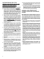
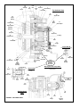
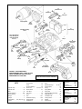
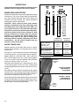
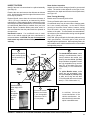
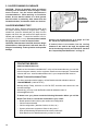
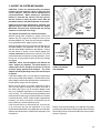
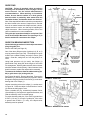
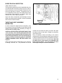
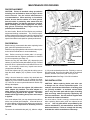
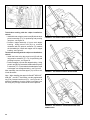
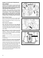
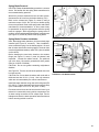
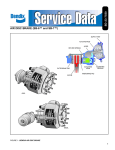
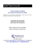
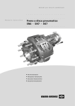
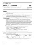
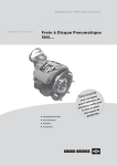
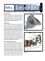
SD-23-7541
Bendix® ADB 22X™, ADB 225™, SN6™, SN7™, SK7™ Air Disc Brakes
DESCRIPTION
Bendix® Air Disc Brakes use a floating caliper design to
provide foundation braking on all axles of heavy commercial
vehicles, buses and trailers. Bendix Air Disc Brakes
provide safety and performance, as well as ease of service.
Available in models with or without a combination spring
brake unit, these brakes may also include optional wear
sensors and/or wear diagnostic equipment.
OPERATION
Bendix Air Disc Brakes convert air pressure into braking
force. (See Figure 2.) When the vehicle brakes are
applied, air enters the service brake chamber through
the supply port, applying pressure within the diaphragm.
The pressure expands the diaphragm, applying force to,
and moving the pressure plate and pushrod forward. The
pushrod acts against a cup in the internal lever which
pivots on an eccentric bearing moving the bridge. Moving
against a return spring, the bridge transfers the motion to
two threaded tubes and tappets, which move the inner
brake pad. The inner brake pad (from its normal position of
having a running clearance between it and the rotor) moves
into contact with the brake rotor. Further movement of the
bridge forces the caliper, sliding on two stationary guide
pins, away from the rotor, which pulls the outer brake pad
into the rotor. The clamping action of the brake pads on
the rotor applies braking force to the wheel.
FIGURE 1 - BENDIX® ADB 22X™ AIR DISC BRAKE
Service Brake
Chamber
Lever
Pressure
Plate
Supply Port
Pushrod
Return Spring
Brake Release and Adjustment
When the vehicle brakes are released, the air pressure
in the service brake chamber is exhausted and the return
springs in the chamber and the bridge return the air disc
brake to a neutral, non-braked position. To maintain the
running clearance gap between the rotor and the brake
pads over time, the non-braked position is mechanically
adjusted by a mechanism in the caliper. The adjustment
mechanism operates automatically whenever the brakes
are activated, to compensate for rotor and brake pad wear
and to keep the running clearance constant. During pad
or rotor maintenance, the technician manually sets the
system’s initial non-braked position. The total running
clearance (sum of clearances on both sides of the rotor)
should be between 0.024 to 0.043 in. (0.6 and 1.1 mm).
Diaphragm
Outer Brake
Pad
Inner Brake Pad
Bridge
Eccentric Bearing
Rotor
FIGURE 2 - CROSS-SECTION VIEW SHOWING BRAKE
OPERATION
1
SAFE MAINTENANCE PRACTICES
WARNING! PLEASE READ AND FOLLOW
THESE INSTRUCTIONS TO AVOID
PERSONAL INJURY OR DEATH:
When working on or around a vehicle, the following
general precautions should be observed at all times:
1. Park the vehicle on a level surface, apply the parking
brakes, and always block the wheels. Always wear
safety glasses. Where specifically directed, the
parking brakes may have to be released, and/or
spring brakes caged, and this will require that the
vehicle be prevented from moving by other means
for the duration of these tests/procedures.
2. Stop the engine and remove ignition key when
working under or around the vehicle. When working
in the engine compartment, the engine should be
shut off and the ignition key should be removed.
Where circumstances require that the engine be in
operation, EXTREME CAUTION should be used to
prevent personal injury resulting from contact with
moving, rotating, leaking, heated or electrically
charged components.
3. Do not attempt to install, remove, disassemble
or assemble a component until you have read
and thoroughly understand the recommended
procedures. Use only the proper tools and observe
all precautions pertaining to use of those tools.
4. If the work is being performed on the vehicle’s
air brake system, or any auxiliary pressurized air
systems, make certain to drain the air pressure from
all reservoirs before beginning ANY work on the
vehicle. If the vehicle is equipped with an AD-IS® air
dryer system or a dryer reservoir module, be sure
to drain the purge reservoir.
5. Following the vehicle manufacturer’s recommended
procedures, deactivate the electrical system in a
manner that safely removes all electrical power from
the vehicle.
6. Never exceed manufacturer ’s recommended
pressures.
7. Never connect or disconnect a hose or line
containing pressure; it may whip. Never remove a
component or plug unless you are certain all system
pressure has been depleted.
8. Use only genuine Bendix ® replacement parts,
components and kits. Replacement hardware,
tubing, hose, fittings, etc. must be of equivalent
size, type and strength as original equipment and
be designed specifically for such applications and
systems.
9. Components with stripped threads or damaged
parts should be replaced rather than repaired. Do
not attempt repairs requiring machining or welding
unless specifically stated and approved by the
vehicle and component manufacturer.
2
10. Prior to returning the vehicle to service, make certain
all components and systems are restored to their
proper operating condition.
11. For vehicles with Antilock Traction Control (ATC),
the ATC function must be disabled (ATC indicator
lamp should be ON) prior to performing any vehicle
maintenance where one or more wheels on a drive
axle are lifted off the ground and moving.
WARNING: AVOID CREATING DUST.
POSSIBLE CANCER AND LUNG DISEASE
HAZARD.
While Bendix Spicer Foundation Brake LLC does not
offer asbestos brake linings, the long-term affects of
some non-asbestos fibers have not been determined.
Current OSHA Regulations cover exposure levels to
some components of non-asbestos linings but not all.
The following precautions must be used when handling
these materials.
• Avoid creating dust. Compressed air or dry brushing
must never be used for cleaning brake assemblies or
the work area.
• Bendix recommends that workers doing brake work
must take steps to minimize exposure to airborne
brake lining particles. Proper procedures to reduce
exposure include working in a well-ventilated area,
segregation of areas where brake work is done, use
of local filtered ventilation systems or use of enclosed
cells with filtered vacuums. Respirators approved by
the Mine Safety and Health Administration (MSHA) or
National Institute for Occupational Safety and Health
(NIOSH) should be worn at all times during brake
servicing.
• Workers must wash before eating, drinking or
smoking; shower after working, and should not wear
work clothes home. Work clothes should be vacuumed
and laundered separately without shaking.
• OSHA Regulations regarding testing, disposal of waste
and methods of reducing exposure for asbestos are
set forth in 29 Code of Federal Regulations §1910.001.
These Regulations provide valuable information
which can be utilized to reduce exposure to airborne
particles.
• Material Safety Data Sheets on this product, as
required by OSHA, are available from Bendix. Call
1-800-247-2725 and speak to the Tech Team or e-mail
[email protected]
SERVICE DATA INDEX
Overview . . . . . . . . . . . . . . . . . . . . . . . . . . . . . . . . . . 1
Safe Maintenance Practices. . . . . . . . . . . . . . . . . . . . 2
Air Disc Brake Sectional and Exploded Views . . . . .4-5
Air Disc Brake Identification . . . . . . . . . . . . . . . . . . . . 6
Rotor Identification . . . . . . . . . . . . . . . . . . . . . . . . . . . 6
Electronic Wear Indicator Exploded Views. . . . . . . . . 6
Preventive Maintenance
Preventive Maintenance Schedule . . . . . . . . . . . . . . . 7
Running Clearance Inspection . . . . . . . . . . . . . . . . . . 7
Mechanical Wear Indicators . . . . . . . . . . . . . . . . . . .8-9
Electronic Wear Indicators, including
Hand Held Diagnostic Equipment . . . . . . . . . . . . . 10
Troubleshooting
Troubleshooting Flowchart . . . . . . . . . . . . . . . . . . . . 11
Inspections
Brake Pads . . . . . . . . . . . . . . . . . . . . . . . . . . . . . . . . 12
Rotors . . . . . . . . . . . . . . . . . . . . . . . . . . . . . . . . . . . . 13
Caliper Running Clearance . . . . . . . . . . . . . . . . . . . 14
Adjuster Mechanism . . . . . . . . . . . . . . . . . . . . . . . . . 15
Guide Pins . . . . . . . . . . . . . . . . . . . . . . . . . . . . . .16-17
Maintenance Procedures
Pad Replacement . . . . . . . . . . . . . . . . . . . . . . . . .18-19
Electronic Wear Indicator Replacement . . . . . . . .20-21
Tappet and Boot Assemblies
Replacement . . . . . . . . . . . . . . . . . . . . . . . . . . . .22-24
Carrier/Caliper Assembly Replacement . . . . . . . . . . 25
Brake Actuator and Spring
Brake Replacement . . . . . . . . . . . . . . . . . . . . . . .26-27
3
12
Pad
Assembly
58
Ring
1
Caliper
9
Inner
Boot
22
5
7
Guide Inner Seal
Brass Bushing
Pin
40
Caliper Bolt
Top Sectional View
10
Cover
23
Adjuster Unit
161
Tappet
Bushing
32
Chain
Wheel
16
Threaded Tube
13
Tappet and Boot
Assembly
61
Shear Adapter
45 Washer
26
Spring Clip
37
Adjuster Cap
44
Pad Retainer Pin
27 Spring
30
Chain
11
Pad Retainer
17
Bridge
22
Inner
Seal
33
Wear Sensor
Caliper Bolt B
(Uses Solid Rubber Bushing)
24
Turning
Device
68a Cap
16
Threaded Tube
161
Tappet
Bushing
13
Tappet
and Boot
Assembly
2
Carrier
6c Guide Sleeve
2
Carrier
4a
Guide
Pin
6a
39a
Rubber Caliper Bolt
Bushing
9
Inner
Boot
4c
Guide Pin
6b
Rubber
Bushing
(Uses Flexible Rubber Wear
Indicator Sleeve)
Caliper Bolt C
68c
Cover
58
Ring
One of Three
Alternate
Caliper Bolt
Styles Used
39b
Caliper Bolt
Main Diagram shows Caliper Bolt A
(Has External Metal
Cover)
39c
Caliper Bolt
4b
Guide Pin
Pad Assembly 12
18/1 Spring Brake or
18/2
Brake Chamber
12
Pad
Assembly
46
Rotor
Side Sectional
View
FIGURE 4 - SECTIONAL VIEW
4
43
Bolt
27
Spring
19
Lever
17
Bridge
20
Eccentric
Bearing
11
Pad Retainer
44
Pad Retainer Pin
26
Spring Clip
45
Washer
18/1 Spring Brake
58
Ring
18/2
Brake
Chamber
Uses White Assembly
Grease
4c
Guide
Pin
9
Inner
Boot
12/2
4a, 4b
Guide Pin
12/1
One of Three Different
Caliper Bolt Styles are
Used (Designated by
A, B, or C)
1
Caliper
13
Tappet and Boot
Assembly
6b
Rubber
Bushing
39c
Caliper Bolt
68c
Cover
12
Pad Assembly
6c Guide
Sleeve
61
Shear
Adapter
7
Brass
6a
Rubber Bushing
Bushing
37
Adjuster Cap
39a
5
Caliper Bolt
Guide
Pin
39b
Caliper
Bolt
68a Cap
10
Cover
FIGURE 5 - EXPLODED VIEW FOR REFERENCE ONLY - MANY OF THE
PARTS SHOWN ARE ONLY FACTORY
SERVICEABLE AT THIS TIME.
KEY
Adjuster Cap. . . . . . . . . . . . . . . 37
Adjuster Unit . . . . . . . . . . . . . . . 23
Bolt . . . . . . . . . . . . . . . . . . . . . . 43
Brake Chamber . . . . . . . . . . 18/2
Brass Bushing . . . . . . . . . . . . . . 7
Bridge . . . . . . . . . . . . . . . . . . . . 17
Caliper . . . . . . . . . . . . . . . . . . . . 1
Caliper Bolt . . . . 39a, 39b, 39c, 40
Carrier. . . . . . . . . . . . . . . . . . . . . 2
40
Caliper Bolt
58
9
Ring
Inner
Boot
Pre-Applied
Thread Adhesive
161
Tappet
Bushing
22
Inner Seal
Uses
White
Assembly
Grease
2
Carrier
See Figure 9, on Page 6 for exploded
views of electronic wear indicators
Chain . . . . . . . . . . . . . . . . . . . . 30
Chain Wheel . . . . . . . . . . . . . . . 32
Cover . . . . . . . . . . . . . . . . . . . . 10
Eccentric Bearing . . . . . . . . . . . 20
Guide Pins . . . . . . . . 4a, 4b, 4c, 5
Guide Sleeve . . . . . . . . . . . . . . 6c
Inner Boot . . . . . . . . . . . . . . . . . . 9
Inner Seal . . . . . . . . . . . . . . . . . 22
Lever . . . . . . . . . . . . . . . . . . . . 19
Pad . . . . . . . . . . . . . . . . . . . . 12/1
Pad Holder Spring . . . . . . . . 12/2
Pad Assembly. . . . . . . . . . . . . . 12
Pad Retainer . . . . . . . . . . . . . . 11
Pad Retainer Pin . . . . . . . . . . . 44
Ring . . . . . . . . . . . . . . . . . . . . . 58
Rubber Bushings . . . . . 6a, 6b, 6c
Shear Adapter . . . . . . . . . . . . . 61
Spring . . . . . . . . . . . . . . . . . . . . 27
Spring Brake. . . . . . . . . . . . . 18/1
Spring Clip . . . . . . . . . . . . . . . . 26
Tappet and Boot Assembly . . . . 13
Tappet Bushing. . . . . . . . . . . . 161
Threaded Tube . . . . . . . . . . . . . 16
Turning Device . . . . . . . . . . . . . 24
Washer . . . . . . . . . . . . . . . . . . . 45
Wear Sensor. . . . . . . . . . . . . . . 33
Caliper Bolt A
Caliper Bolt . . . . . . . . 39a
Cap . . . . . . . . . . . . . . 68a
Guide Pin . . . . . . . . . . 4a
Rubber Bushing . . . . . 6a
Caliper Bolt B
Caliper Bolt . . . . . . . . 39b
Guide Pin . . . . . . . . . . 4b
Rubber Bushing . . . . . 6b
Caliper Bolt C
Caliper Bolt . . . . . . . . 39c
Guide Pin . . . . . . . . . . 4c
Cover . . . . . . . . . . . . 68c
5
AIR DISC BRAKE IDENTIFICATION
ROTOR IDENTIFICATION
To determine which version of the Bendix air disc brake is
installed, locate the identification label near the guide pin
housing. See below for examples of the different styles of
label you may find.
Certain maintenance inspection procedures depend on
the type of rotor installed (See Page 13). See below for
examples of the different styles of rotor in use.
Spline Rotor
Conventional Rotor
FIGURE 6 - PART NUMBER LABEL LOCATION
Bendix Part No.
Serial No.
Brake Designation followed
by the Caliper/Carrier part
number
Some air disc brakes carry the
Knorr-Bremse label shown below.
Part No.
FIGURE 8 - ROTOR IDENTIFICATION
Axle or Vehicle
Manufacturer's No.
Type of
Caliper
Date of Manufacture
FIGURE 7 - PART NUMBER LABEL FIELDS
104
Cable Protection
Plate
101
Sensor
104
Cable Protection
Plate
101
Sensor
Type 1
101
Sensor
105 Cable
Guide
11 Pad
Retainer
101
Sensor
Type 3
105a
Cable
Guide
104
Cable Protection
Plate
Type 2
101
Sensor
101
Sensor
101
Sensor
103
Alternative to
Item 105
105
Cable Guide
11 Pad Retainer
FIGURE 9 - ELECTRONIC WEAR INDICATOR COMPONENTS
6
101
Sensor
105
Cable Guide
11 Pad
Retainer
103
Cable to Electrical
Supply
Pad Retainer . . . . . . . . . . . . . . 11
Sensor . . . . . . . . . . . . . . . . . . 101
Cable to Electrical Supply . . . 103
Cable Protection Plate . . . . . . 104
Cable Guide . . . . . . . . . . . . . . 105
Cable Guide . . . . . . . . . . . . . 105a
PREVENTIVE MAINTENANCE
Regular inspection and maintenance of air disc brake
components is an important part of vehicle maintenance.
The maintenance practices outlined here are recommended
in addition to all standard industry practices (including e.g.
daily pre-trip inspections, etc.) Also, see the vehicle's
manual for recommendations.
Use the table below for a guide to maintenance interval
planning, however, depending on the vehicle use, more
frequent checks of the components may be necessary.
Keep track of the results of your maintenance inspections to assist you determine the ideal maintenance
interval for the vehicle.
Basic Inspection Program
Vehicle Used for:
Over the Road
e.g. Line haul, RV,
Open Highway Coach.
Pad & Rotor Wear,
Running Clearance
(Inspection with the wheel mounted)
• For vehicles with electronic wear indicators,
use the dash indicator(s) and/or the hand-held
diagnostic tool to regularly monitor the pad
wear.
• In all cases, visually inspect the wear indicator
(see Pages 8-9) every four months (or keep
track of the results of maintenance inspections
to schedule checks 4 to 5 times during the
pad lifetime). At the same time, conduct the
Running Clearance Inspection (see below).
• A visual check of the mechanical wear indicator
every time the tire pressures are checked is
recommended. Be alert for any rotor cracks,
etc. visible (See Page 13 for criteria.)
Higher Duty Use
e.g. Pick-Up & Delivery,
Off-Highway, Construction,
Loggers, Concrete Mixer,
Dump Truck,
City Transit Bus, Refuse,
Urban Region Coach,
School Bus.
At Least Once Annually and at
Every Pad Replacement
(Inspection with wheel removed)
• For vehicles with electronic wear indicators,
use the dash indicator(s) and/or the hand-held
diagnostic tool to regularly monitor the pad
wear.
• In all cases, visually inspect the wear indicator
(see Pages 8-9) every three months (or keep
track of the results of maintenance inspections
to schedule checks 4 to 5 times during the
pad lifetime). At the same time, conduct the
Running Clearance Inspection (see below).
• A visual check of the mechanical wear indicator
every time the tire pressures are checked is
recommended. Be alert for any rotor cracks,
etc. visible (See Page 13 for criteria.)
Inspect:
• The rotor for cracks, etc. (see
Page 13 for criteria)
• The running clearance
and adjuster function (see
Page 15)
• The caliper travel (see Pages
16-17)
• The tappet and boot
assemblies (see Page 14)
• All covers, caps, hoses, and
brake exterior for damage etc.
Air Disc Brake Running Clearance Inspection.
Follow all industry safety guidelines, including those listed on Page 2. On
level ground, with the wheels chocked and the parking brake temporarily
released, check for movement of the brake caliper. This small movement,
less than 0.80" (2 mm) - approximately the thickness of a nickel - in the
inboard/outboard direction indicates that the brake is moving properly
on its guide pins. If the caliper has no movement or appears to move
greater than the distances above, a full wheel-removed inspection will be
necessary. See Page 16.
7
MECHANICAL BRAKE PAD AND ROTOR WEAR INDICATORS
A preliminary visual check of the condition of the brake pad/rotor
wear can be made without removing the wheels. See below
for the inspection to make for each of the three guide pin styles
in use for Bendix air disc brakes.
Note: These inspections provide an indication of
when to schedule a full wheel-removed inspection of
the brake pads and rotor. The thicknesses of both the
pad and rotor will affect the wear indicator position at
which maintenance is actually needed.
These inspections do not constitute
“out-of-service” criteria.
Style A and B
- Inspect position
of wear indicator
pin
Style C and D Where the indicator
pin is covered (see
Figure 12), inspect
notches in carrier
and caliper or
backing plate - see
Page 9
Style A: Rolling Boot Style Wear Indicator
Inspect the position of the guide pin
flexible rubber bushing. See Figure
10. When the guide pin has moved
in so that the ribbed section of the
flexible rubber bushing reaches the
point where it folds back in, it is time
to schedule a full wheel-removed
inspection of the pads and rotor. Note:
This is only an indication that the pads
and rotor are ready for inspection,
and does not necessarily mean that
maintenance is required.
New
Time to Schedule
Inspection of
Pads and Rotor
FIGURE 10 - ROLLING BOOT-STYLE WEAR INDICATOR INSPECTION
Style B: Solid Rubber Bushing Style Wear Indicator
Inspect the position of the guide pin
compared to the solid rubber bushing.
See Figure 11. When the guide pin
is aligned with the bushing, it is time
to schedule a full wheel-removed
inspection of the pads and rotor. Note:
This is only an indication that the pads
and rotor are ready for inspection,
and does not necessarily mean that
maintenance is required.
New
Time to Schedule
Inspect ion of
Pads and Rotor
FIGURE 11 - SOLID RUBBER BUSHING-STYLE WEAR INDICATOR INSPECTION
FIGURE 12 - PIN COVER
Where the Guide Pin is enclosed
by a cover - see next page for
inspection criteria.
8
MECHANICAL BRAKE PAD AND ROTOR WEAR INDICATORS (continued)
Style C: Where Both the Carrier and Caliper
Have an Indicator Notch
Compare the relative position of two notches cast into the
Carrier and Caliper. See Figure 13. When the two notches
align, it is time to schedule a full wheel-removed inspection
of the pads and rotor. Note: This is only an indication that
the pads and rotor are ready for inspection, and does not
necessarily mean that maintenance is required.
Location of
Inspection
Grooves
Notch in Caliper
Notch in
Carrier
Notches
Line Up
Time to Schedule
Inspection of
Pads and Rotor
FIGURE 13 - STYLE C - NOTCHED
CARRIER AND CALIPER
Notch in
Caliper
Style D: Where Only the Caliper has an
Indicator Notch
When the notch in the Carrier aligns with the front edge of
the torque plate, it is time to schedule a full wheel-removed
inspection of the pads and rotor. Note: This is only an
indication that the pads and rotor are ready for inspection,
and does not necessarily mean that maintenance is
required.
FIGURE 14 - CARRIER WEAR
INDICATOR NOTCH AND BACKING
PLATE ALIGNMENT
Backing
Plate
Lines Up
Torque
Plate
Time to Schedule
Inspection of
Pads and Rotor
9
11
Pad Retainer
101
Wear Sensor
Cable
Example of
a Wear Sensor
(101) Installed into
Slot in Brake Pad
To Vehicle Electronic
Monitoring System
or for use with
Diagnostic Tool
12
Brake Pad Assembly
46 Rotor
FIGURE 15 - EXAMPLE OF NORMALLY OPEN OR CLOSED
WEAR SENSOR
FIGURE 16 - EXAMPLE OF POTENTIOMETER WEAR
SENSOR
ELECTRONIC BRAKE PAD WEAR
INDICATORS
The electronic monitoring system uses sensors installed
in a pre-formed slot in the brake pad to allow the status of
the pad wear to be monitored. When the pad wears away
through use, the point is reached when the indicator itself
comes into contact with the rotor.
13-Pin Plug
(DIN 72570)
to vehicle
For in-pad Normally-Closed Indicators, when the point
is reached when the indicator itself is worn through, the
circuit flowing through it is broken and the vehicle operator
is alerted.
For in-pad Normally-Open Indicators, when the point
is reached when the indicator itself is worn through, the
circuit is completed by the rotor touching the contacts and
the vehicle operator is again alerted.
On some vehicles, the electronic system is fully integrated
into the vehicle monitoring system and uses a buzzer
or indicator lamp to alert the driver. Alternate vehicle
arrangements permit a hand-held diagnostic tool to be
used to test individual wheel connectors, or where installed,
attach to a DIN socket in the dash, and allow up to six
brakes to be checked from that location. The system
provides feedback on the pad wear and can also conduct
a test of the Wear Indicator Potentiometer.
Even when using wear indicators, always follow the
standard preventive maintenance schedule outlined on
page 7.
Refer to the vehicle manual and/or the diagnostic tool
manual for specific device operating instructions.
10
Plug for Individual
Wheel Inspection
FIGURE 17 - HAND HELD DIAGNOSTIC TOOL
GENERAL TROUBLESHOOTING PROCEDURE FLOWCHART
FIGURE 18 - TROUBLESHOOTING BENDIX AIR DISC BRAKES
11
INSPECTIONS
Follow all standard safety procedures including, but not
limited to, those on page 2 of this service manual.
BRAKE PADS AND ROTORS
Bendix Air Disc Brakes are precision-engineered braking
mechanisms. The “friction couple” braking characteristics
have been carefully optimized and the rotor design and
materials have been matched with special formulation
brake pads for optimal performance.
CAUTION: When replacing brake pads, Bendix
strongly recommends using only replacement pads
and replacement rotors approved by the OEM. Use
of non-approved rotors or non-approved replacement
disc pads can cause excess wear to brake components,
and can increase the risks of rotor cracking, etc. Note
that two thicknesses of backing plate are generally
available, so to maintain the vehicle within spec's
only use brake pads with the type of backing plate
and lining material originally supplied by the vehicle
manufacturer. See the manual supplied with the
vehicle for further information.
INSPECT BRAKE PADS
Regular inspection of the brake pads (even for vehicles
that use a wear indicator) is an important part of vehicle
maintenance.
See Figure 16. If the thickness of the friction material (M2)
is less than 0.079 in. (2 mm) the pads must be replaced.
Bendix® ADB 22X™, ADB 225™, SN6™, SN7™ (and some
SK7™) air disc brakes use 0.35 in. (9 mm) backing plates,
so P2 (the combined pad and backing plate thickness)
must be a minimum of 0.43 in. (11 mm).
Note that for some Bendix® SK7™ air disc brakes, a 0.28 in.
(7 mm) backing plate is used, so P2 (the combined pad
and backing plate thickness) must be a minimum of 0.35 in.
(9 mm).
B (Backing
P2 (Pad min.
plate thickness) thickness)
Bendix® ADB 22X™,
ADB 225™, SN6™,
and some SK7™
Air Disc Brake Pads
SK7™ Air Disc Brake
Pads with 0.28 in.
(7 mm) backing plate
0.35 in.
(9 mm.)
0.43 in.
(11 mm.)
0.28 in.
(7 mm.)
0.35 in.
(9 mm.)
FIGURE 19 - PAD AND ROTOR DIMENSIONS
Small Amount of
Brake Material
Chipped from
Edge
FIGURE 20 - MINOR
PAD DAMAGE IS
ACCEPTABLE
If the pad thickness is within the acceptable range, inspect
the pad surface. Minor damage at the edges is permitted
(see Figure 20), but replace the pads if major damage on
the surface of the pad is found (see Figure 21).
When replacing brake pads, Bendix strongly recommends
that all the brake pads on an axle be replaced at one time.
See pages 18-19 for the pad replacement procedure. Also
see the vehicle manual recommendations.
12
FIGURE 21 - MAJOR
PAD DAMAGE IS
NOT ACCEPTABLE
Section
Damaged or
Missing
INSPECT ROTORS
Rotor Surface Inspection
Identify if the rotor is a conventional or a splined assembly
(see Page 6).
Inspect the rotor at each change of pads for grooves and
cracks. The action to take depends on the type of rotor,
and also the size, depth and direction of the imperfections,
see Figure 22.
Examine the rotor and measure the thickness at thinnest
point. Avoid measuring near the edge of the rotor as minor
burrs may be present.
Replace Bendix rotors when the minimum thickness of
1.46 in. (37 mm) is reached or as instructed by vehicle
manufacturer. When replacing Rotors, please refer to the
instructions of the Vehicle Manufacturer. It is recommended
to install Bendix Brake Rotors, available from your local
Bendix Spicer Foundation Brake parts outlet, and it is
also recommended that the pads should be replaced at
the same time.
Non-Bendix rotors. If a non-Bendix rotor is used,
refer to the vehicle manual and rotor manufacturer’s
recommendations. CAUTION: The use of non-approved
brake rotors may reduce levels of safety and invalidate
warranty.
Rotor Turning (Grinding)
Bendix rotors are normally service-free.
Turning of Bendix spline rotors is not permitted.
Conventional rotors may be turned when changing pads,
but is not normally necessary. In the case of severe
grooving of the entire friction surface, however, turning
could be useful, and may increase the load-bearing
surface of the pads. To meet Bendix recommendations,
the minimum rotor thickness after turning must be greater
than 1.53 in. (39 mm).
CAUTION: Always maintain air disc brake pads and rotors
within specifications. Excessive pad or rotor wear will
degrade optimum performance. When replacing Rotors, be
sure to adhere to the vehicle manufacturer’s recommended
bolt tightening torques.
B
A
No action is needed for
small cracks spread
over the surface (e.g.
Area A)
Rotor
Friction
Surface
Width
“a”
a
Area D
D
Cracks reaching
either edge of the
rotor
are not
acceptable
for either
type of
rotor
• For standard Bendix rotors, cracks
running in a radial direction, that is,
from the inside to the outside, (see
Area B), less than 0.06 in. (1.5 mm)
deep or wide are acceptable. Cracks
are only acceptable if they are less
than 75% of the width of the rotor
contact area (i.e. 75% of dimension
“a”).
Area B
Area A
Area C
• For spline Bendix rotors, radial
cracks are only acceptable if they
are less than 0.04 in. (1.0 mm) deep
or wide, and if they are less than
75% of the width of the rotor contact
area (i.e. 75% of dimension “a”).
C
Circumferential
Grooves, as in Area
C, are acceptable
if less than 0.06 in.
(1.5 mm) deep.
In addition, follow the
recommendations of the
vehicle manufacturer. An
axle should only have either
spline or standard rotors.
FIGURE 22 - EXAMPLES OF ACCEPTABLE AND NON-ACCEPTABLE ROTOR CRACKS AND GROOVES
13
2. CALIPER RUNNING CLEARANCE
CAUTION: Follow all standard safety procedures
including, but not limited to, those on page 2 of this
service manual. See the vehicle manufacturer's
recommendations. When working on foundation
brakes, be sure that the vehicle is on level ground,
that the vehicle is parked by other means than the
foundation brakes, and that the wheels are chocked.
FIGURE 23 MEASURING
THE RUNNING
CLEARANCE
CALIPER MOVEMENT TEST
Remove the wheel. With the spring brakes caged, push
the caliper assembly inboard on its guide pins. Using a
suitable tool, press the inboard pad (12) away from the
tappets and check the gap between the tappet and the
inboard pad backplate - it should be between 0.024 in.
(0.6 mm) & 0.043 in. (1.1 mm). If the movement is within
the range there is no need to inspect further.
CAUTION: If the clearance is too wide, there is a danger
of brake failure. If the clearance is too small, there is a
danger of overheating. That may lead to consequential
damage.
If there is no movement at all, go to pages 16-17 for
the “Guide Pin Inspection Procedure.”
If instead, there is movement, but the running
clearance is too small or too large, the adjuster may
not be functioning correctly and should be checked.
See “Inspect Adjuster Mechanism” on Page 15.
CONTACTING BENDIX
www.foundationbrakes.com
Bendix on-line information is available 24/7. In the on-line contacts directory, you can find:
technical support contacts; service engineers; Bendix account managers; international
contacts and more. www.foundationbrakes.com is your complete Bendix resource.
Bendix Technical Assistance Team
For direct personal technical support, call the Bendix technical assistance team at:
1-800-AIR-BRAKE (1-800-247-2725),
Monday through Friday, 8:00 A.M. to 6:00 P.M. EST, and follow the instructions in the
recorded message.
Alternatively, you may e-mail the Bendix technical assistance team at:
[email protected].
To better serve you, please record the following information before you call the
Bendix Tech Team, or include this information in your e-mail:
• Bendix product model number, part number and configuration.
• Vehicle make and model.
• Vehicle configuration. (Number of axles, tire size, etc.)
• System performance symptoms: When do they occur?
• What troubleshooting/measurements have been performed?
• What Bendix service data literature do you have or need?
14
3. INSPECT ADJUSTER MECHANISM
CAUTION: Follow all standard safety procedures
including, but not limited to, those on page 2 of this
service manual. See the vehicle manufacturer's
recommendations. When working on foundation
brakes, be sure that the vehicle is on level ground,
that the vehicle is parked by other means than the
foundation brakes, and that the wheels are chocked.
61
Aside from the normal maintenance schedule, this
Adjuster Check is also carried out when the Caliper
Movement Test (see Page 14) finds that the running
clearance is too small or too large.
12
Outboard
Brake Pad
The adjuster should then be checked as follows:
With the spring brake released (or caged), remove the
adjuster cap (37) using the tab, taking care not to move
the shear adapter (61). Note: One of two styles of adjuster
cover (stamped metal or plastic) may be used.
Although exploded view (Figure 25) shows the adjuster (23)
and shear adapter (61) separated, only turn the adjuster
with the shear adapter installed on the adjuster. Using a
box-end wrench or socket, turn the Shear Adapter (61)
counter-clockwise and listen for the sound of 2 or 3 clicks
as the mechanism increases the running clearance. Note:
Do not use an open-ended wrench as this may damage
the adapter.
CAUTION: Never turn the adjuster (23) without the
shear adapter (61) installed. The shear adapter is a
safety feature and is designed to prevent an excess
of torque being applied to the adjuster. The shear
adapter will fail (by breaking loose) if too much torque
is applied.
37
12
Inboard
Brake
Pad
FIGURE 24 - COVER REMOVAL
37
Cap
23 Adjuster
61 Adapter
Tab
37
Cap
FIGURE 25 - EXPLODED
VIEW OF ADJUSTER
AND ADAPTER
Tab
FIGURE 26 - TAB
POSITION
If the shear adapter fails, you may attempt a second time
with a new (unused) shear adapter. A second failure of the
shear adapter confirms that the adjustment mechanism is
seized and the caliper must be replaced.
With a box-end wrench (or socket) positioned so that it
can turn freely without coming into contact with parts of
the vehicle (See Figure 27) on the shear adapter, make
five to ten moderate applications of the brakes [at about
30 psi (2 Bar)]. For a normally functioning Bendix air disc
brake, the box-end wrench or socket should turn clockwise
in small increments. NOTE: As the number of applications
increases, the turning movement will decrease (as the
brake reaches its normal calibration point).
If the box-end wrench or socket does not: (a) turn at all,
or (b) turns only with the first application, or (c) turns
forward and backward with every application, the automatic
adjuster has failed and the caliper/carrier assembly must
be replaced.
FIGURE 27 - ADJUSTMENT MECHANISM TEST
Bendix recommends installing a new adjuster cap (lightly
greased using white lithium-based grease) when returning
the air brake to service. Ensure that the tab is in the position
shown in Figure 26.
15
GUIDE PINS
CAUTION: Follow all standard safety procedures
including, but not limited to, those on page 2 of this
service manual. See the vehicle manufacturer's
recommendations. When working on foundation
brakes, be sure that the vehicle is on level ground,
that the vehicle is parked by other means than the
foundation brakes, and that the wheels are chocked.
13
Tappet and Boot
1
Assembly
Caliper
7
Brass Bushing
5
Guide Pin
10
Cover
LONG
BEARING SIDE
23
Adjuster Unit
61
Shear Adapter
Note: If the steps below lead the technician to a step where
the wheel needs to be removed, inspect first to see that
there is no contact between the caliper and axle, vehicle,
chassis sections or carrier, etc. that may be impeding the
caliper movement. When removing wheels, refer to the
vehicle manufacturer’s recommendations.
37
Adjuster
Cap
This guide pin inspection should be carried out if the
result of the Caliper Movement Test (see Page 13) is
that the technician cannot move the caliper.
SHORT
BEARING SIDE
GUIDE PIN BEARING INSPECTION
Use the following procedure to check caliper movement
along the guide pins:
68a
Cap
Remove the Pads (see Page 18).
One of the three different styles of guide pin (A, B, or C)
may be present (See Figure 28). The bearings for styles
A and B use a rubber bushing, and style C uses a guide
sleeve. Clean dirt, road grime, etc. from the guide pin or
cover.
Using hand pressure only (no tools), the Caliper (1)
should slide freely along the whole length of the Guide
Pin arrangement. With the pads removed, this movement
should be at least 0.8 inch (20mm). If the movement is less
than this amount, replace the caliper/carrier assembly.
To measure the clearance from the rubber bushing (6a,
6b) or guide sleeve (6c) to the guide pin:
See Figures 29 and 30. Remove the wheel. Remove the
pad retainer (11), but leave the pads (12) in position. Attach
a magnetic dial-gauge holder to the carrier (2) on the short
bearing side of the caliper (1).
Caliper
Movement
39a
6a
4a
4b 6b 39b
6c Guide Sleeve
39c
Caliper Bolt
68c
Cover
4c Guide Pin
FIGURE 28 - GUIDE PINS
12 Pad Assembly
1
Carrier
Use the measuring point on the caliper (1) - see the arrow
in Figure 28. Press the caliper in the direction of carrier
(2) and set the dial-gauge to zero.
Place a suitable tool (e.g. screwdriver) between Carrier
(2) and Caliper (1) forcing them in opposite directions, and
read the maximum value on the dial-gauge.
For styles A and B guide pins, if the value is greater than
0.079 in. (2.0 mm), or for style C guide pins, if the value
is greater than 0.039 in. (1.0 mm), the caliper/carrier
assembly must be replaced.
2
Caliper
FIGURE 29 - MAGNETIC DIAL-GAUGE
16
(6a): Rubber Bushing
(39a): Caliper Bolt
(4a): Guide Pin
(6b): Rubber Bushing
(39b): Caliper Bolt
(4b): Guide Pin
GUIDE PIN SEAL INSPECTION
Caliper Guide Pin Seals
The long bearing side guide pin (5) is sealed with the cover
(10) and with the inner boot (9). See Figure 28. Note: It
may be necessary to remove the pads to inspect the inner
boots (9) if pad wear is minimal. The guide pin (4a, 4b,
or 4c, depending on the style) is also sealed with an inner
boot (9) and a cover (style C), or a flexible rubber wear
indicator in the case of style A guide pins.
Inspect the above components, and if damage is found,
replace the caliper/carrier assembly. No kits are available
at this time for Guide Pin Seals.
TAPPET AND BOOT ASSEMBLY
INSPECTION
In order to inspect the tappet and boot assembly, it may
be necessary to remove the pads (12) (see Page 18) and
advance the shear adapter (61) clockwise (see Page 15)
until the boots are clearly visible.
CAUTION: NEVER EXTEND THE TAPPET MORE THAN
1.18 in. (30 mm). Over-extending the tappet will result
in the tappet losing engagement with the threads of the
synchronizing mechanism. Since the mechanism can
only be set at the manufacturing plant, the CALIPER/
CARRIER ASSEMBLY MUST BE REPLACED if this
happens.
Inspect the tappet and boot assemblies (13) for evidence
of damage, corrosion, etc. The penetration of dirt and
13
Extend Less
Than 1.18 in.
(30 mm)
FIGURE 30 - TAPPET EXTENSION LIMIT
moisture into the brake can lead to corrosion and impair
the function of the air disc brake. Replace as necessary
(see Pages 22-24).
After re-installing a wheel according to the vehicle
manufacturer’s recommendations, please ensure that there
is sufficient clearance between the tire inflation valve stem,
the caliper and the wheel rim, to avoid damage. Note: Not
all wheels (and or valve stems) are compatible with
Bendix Air Disc Brakes. Use only wheels and valve
stems approved by the vehicle manufacturer.
17
MAINTENANCE PROCEDURES
PAD REPLACEMENT
CAUTION: Follow all standard safety procedures
including, but not limited to, those on page 2 of this
service manual. See the vehicle manufacturer's
recommendations. When working on foundation
brakes, be sure that the vehicle is on level ground,
that the vehicle is parked by other means than the
foundation brakes, and that the wheels are chocked.
When installing pads, where appropriate use heavy
duty gloves and always keep fingers away from
potential pinch hazard areas.
As noted earlier, Bendix Air Disc Brakes are precisionengineered braking mechanisms. The “friction couple”
braking characteristics have been carefully optimized and
the rotor design and materials have been matched with
special formulation brake pads for optimal performance.
PAD REMOVAL
Bendix strongly recommends that when replacing brake
pads, pads are replaced as an axle set.
44
Pin
11 Pad Retainer
45 Washer
26 Clip
FIGURE 31 - BRAKE PAD REMOVAL
d
oar
Inb
ard
tbo
Ou
23
61
Release or cage spring brakes and remove the wheel (refer
to the vehicle manufacturer’s recommendations).
Note: Before removing the brake pads it is strongly
recommended that the adjuster mechanism be checked
for correct operation (see Page 15).
Remove the clip (26) and washer (45), depress the pad
retainer (11) and remove the pad retainer pin (44). Discard
these four items - replacements are included in the service
kits. As necessary remove any in-pad wear sensor
components and discard.
37
Inboard Pad
12
12
Brake Pad
Assembly
FIGURE 32 - BRAKE PAD REMOVAL
Pull off the adjuster cap (37) using the tab, taking care to
keep the shear adapter (61) in position on the adjuster
(23).
(1) fully to the outboard position first. Similarly, to remove
the inboard pad, first move the caliper fully to the inboard
position, and then remove the pad. See Figure 32.
Using a box-end wrench or socket, fully wind back the
tappet and boot assemblies (13) by rotating the shear
adapter (61) in an counter-clockwise direction (see Page
15). Note: Do not use an open-ended wrench as this may
damage the adapter.
PAD INSTALLATION
CAUTION: Never turn the adjuster (23) without the
shear adapter (61) installed. The shear adapter is a
safety feature and is designed to prevent an excess
of torque being applied to the adjuster. The shear
adapter will fail (by breaking loose) if too much torque
is applied.
If the shear adapter fails, you may attempt a second time
with a new (unused) shear adapter. A second failure of
the shear adapter confirms that the adjustment mechanism
is seized and the caliper/carrier assembly must be
replaced.
To remove the outboard brake pad (12), slide the caliper
18
Inspect the rotor. See Page 13 for full information.
CAUTION: When replacing brake pads take care
to always use the correct replacement pads. For
example, note that two thicknesses of backing plate
are generally available - to maintain vehicle within
spec's only use brake pads with the type of backing
plate and lining material originally supplied by the
vehicle manufacturer. See the manual supplied with
the vehicle for further information.
As noted above, Bendix strongly recommends that
when replacing brake pads, pads are replaced as an
axle set. Use only pads which are permitted by the
vehicle manufacturer, axle manufacturer and/or disc
brake manufacturer. Failure to comply with this may
invalidate the vehicle manufacturer’s warranty.
Check that the tappet and boot assemblies have been fully
retracted, as outlined above. Clean the brake as needed
- see the vehicle manufacturer’s recommendations.
To install the outboard brake pad (12), slide the caliper
(1) fully to the outboard position before inserting the pad
(with the brake lining material facing the rotor). Similarly,
to install the inboard pad, move the caliper fully to the
inboard position, and then install the brake pad (with the
lining material facing the rotor). See Figure 30.
d
oar
Inb
ard
tbo
Ou
23
61
37
Install new in-pad wear indicator kit, if appropriate (see
Pages 20-21).
12
Using a box-end wrench or socket, turn the shear adapter
(61) clockwise until the pads come into contact with the
rotor. Then turn back the shear adapter counter-clockwise
two clicks to set the initial running clearance.
Note: Use only pads with the same backing plate thickness
as originally specified for the vehicle’s brakes.
Note: The Bendix air disc brakes covered by this service
manual use more than one pad retainer design. Be sure
to install the correct part number for the vehicle.
After installing the pad retainer (11) supplied with the kit,
into the groove of the caliper (1), it must be depressed to
enable the insertion of the pad retainer pin (44).
Install the supplied washer (45) and spring clip (26) to
the pad retainer pin (44). It is recommended that the pad
retainer pin (44) be installed pointing downwards (see
Figure 35).
Apply and release the brake and then check that the hub
turns easily by hand.
Lightly grease and install a new adjuster cap (37) using
white lithium-based grease. Note: The tab of the adjuster
cap should be positioned as shown by the arrow in
Figure 34 for ease of access.
Re-install the wheel according to the vehicle manufacturer’s
recommendations. Note: Not all wheels (and or valve
stems) are compatible with Bendix Air Disc Brakes.
Use only wheels and valve stems approved by the
vehicle manufacturer.
CAUTION: Bendix recommends that after every air
brake service, if available, the technician checks the
brake performance and the system behavior on a
dynamometer.
Inboard
Pad
Backplate
of Pad
12
Brake Pad
Assembly
FIGURE 33 - PAD
INSTALLATION
37 Cap
FIGURE 34 - TAB POSITION
Tab
44
Pin
11 Pad Retainer
45 Washer
26 Clip
FIGURE 35 - BRAKE PAD INSTALLATION
19
ELECTRONIC WEAR INDICATOR
REPLACEMENT
(Normally-Closed or Normally-Open Type) See page 10.
1
101
New wear indicators are normally installed whenever brake
pads are replaced. Please see Brake Pad Installation on
Page 18 for cautions and procedures. The wear indicator
is installed after the new brake pads are installed into the
brake, but before the retainer hardware.
Outboard Pad
Remove and retain the pad holder springs.
12/1
See page 6 for typical contents of wear indicator kits.
Installation: The longer branch of the wear indicator cable
(see arrow) must be installed in the outboard pad. Insert
the Wear Indicator Cables (101) into the pre-cut slot in the
pads. The wear indicators snap into place.
2
Long
Cable
FIGURE 36 - WEAR INDICATOR CABLE
3
12/2
12/2
12/1
101
2. Insert wear indicator sensors into
the pads.
4
3. Install the pad holder springs (12/2)
onto the pads (12/1) with the wear
indicator cable (101) as shown.
5
44
11
105
45
26
101
4. Install the pad retainer (11), pad
retainer pin (44), washer (45) and
spring clip (26) with the wear indicator
cable (101) as shown.
20
5. Install the cable guide (105) onto
the pad retainer (11). The cable guide
(105) snaps into place when pressing
lightly onto the pad retainer (11).
12/1
7
6
101
101
105a
short cable end
6. Press the wear indicator cable
(101) into the locating tabs of the
cable guide (105) (see arrows A). The
short cable end of the wear indicator
cable (101) must not be secured by
locating tabs of the cable guide (105).
According to vehicle type, install
the cable that leads to the electrical
supply of the vehicle, in one of the two
locating tabs (see arrows B).
7. Install the indicator cable (101) in
the middle of the pad retainer (11).
Insert the cable guide (105a) at one
side of the pad retainer (11) (see
arrow B). Slightly press in on the
other side of the pad retainer (11) (see
arrows A). The cable guide (105a)
snaps into place.
According to vehicle type, install the
cable that leads to the electric supply
of the vehicle, in one of the wire loop
(see arrows C). The short end of the
wear indicator cable (101) must not
be secured by a wire loop of the cable
guide (105a) (see arrows C).
8
8. Carefully install the cable protection
plate (104) with attention to the correct
position of the cable protection plate’s
catch (see arrows).
The cable protection plate (104) will
snap into place.
21
TAPPET AND BOOT ASSEMBLIES
REPLACEMENT
CAUTION: Follow all standard safety procedures
including, but not limited to, those on page 2 of this
service manual. See the vehicle manufacturer's
recommendations. When working on foundation
brakes, be sure that the vehicle is on level ground,
that the vehicle is parked by other means than the
foundation brakes, and that the wheels are chocked.
When installing pads, where appropriate use heavy
duty gloves and always keep fingers away from
potential pinch hazard areas. Cage spring brakes
before beginning procedure.
Note: In some cases, the technician may find it easier to
remove the caliper from the vehicle before making the
replacement (see Page 25 for instructions on caliper/carrier
removal).
REMOVAL OF TAPPET AND BOOT
ASSEMBLIES (13)
Follow the procedure for removing brake pads (12) on
Page 18.
CAUTION: Never turn the adjuster (23) without the
shear adapter (61) installed. The shear adapter is a
safety feature and is designed to prevent an excess
of torque being applied to the adjuster. The shear
adapter will fail (by breaking loose) if too much torque
is applied.
CAUTION: NEVER EXTEND THE TAPPET MORE THAN
1.18 in. (30 mm). Over-extending the tappet will result
in the tappet losing engagement with the threads of the
synchronizing mechanism. Since the mechanism can
only be set at the manufacturing plant THE CALIPER/
CARRIER ASSEMBLY MUST BE REPLACED if this
happens.
Removal of the tappet and boot assembly (13) requires
the use of the wedge fork (A). See Figure 39. Extend the
tappets less than 1.18 in. (30 mm) by turning the shear
adapter (61) clockwise until there is sufficient access
to the boots to remove the tappet boot from the caliper
bore. A screwdriver (B) should be used to move the boot
location ring - see Figure 40 and allow the wedge fork (A)
to be inserted. CAUTION: Take care not to damage the
inner sealing face (see arrow “X” in Figure 40). Gouges
or grooves that would prevent a good seal necessitate
caliper replacement.
The tappet and boot assemblies (13) can then be removed
from the threaded tubes (16) by using the wedge fork
(A).
Remove the old tappet bushing(s) (161). Inspect the inner
sealing face (see arrow “X”) for damage. If damage is
found to the inner seal the caliper/carrier assembly must
be replaced.
22
d
oar
Inb
ard
tbo
u
O
23
61
37
Inboard Pad
12
12
FIGURE 37 - BRAKE PAD REMOVAL
B
13
13
Extend
Less Than
1.18 in.
(30 mm)
FIGURE 38 - TAPPET EXTENSION
Press-in Tool
arrangement for
Tappet and Boot
Assembly (13)
when Caliper
is fitted on the
vehicle.
Press-in Tool
arrangement for
Tappet and Boot
Assembly (13)
when Caliper is
removed from the
vehicle.
Ring T24 for SK7™ and 225™ and 22X™ Air Disc
Brakes. Installation device for Tappet and
Boot Assembly (13) when Caliper is removed
from axle.
Press-in Tool (Z004190) for Tappet and
Boot Assembly (13) . . . . . . . . . . . . . . . T1, T2 T3, T4
Wedged Fork (II32202) for removal of
Tappet and Boot Assembly (13) . . . . . . . . . . T15
Ring (K004082) for Tappet and
Boot Assembly (13) . . . . . . . . . . . . . . . . . . . T24
FIGURE 39 - TAPPET REMOVAL TOOL
2.76 in.
(70 mm)
13
A
A
22
E
16
X
1
13
FIGURE 42 - USE OF A SPACER (OFF VEHICLE USE)
161
13
B
FIGURE 40 - WEDGE TOOL USE
161
12
16
46
FIGURE 43 - ON VEHICLE BOOT INSTALLATION
FIGURE 41 - USE OF A NEW BRAKE PAD AS A SPACER
INSPECT THE THREADED TUBES (16)
For the inspection of the threads, the tubes must be
extended, but by less than 1.18 in. (30mm), by turning the
shear adapter (61) clockwise. If working with the caliper
on the vehicle, the technician may place a new brake pad
(12) into the outboard gap to help avoid the loss of thread
engagement of the threaded tubes. If the work is being
carried out at a workbench, the technician may insert a 2.76
in. (70 mm) spacer (E) into the caliper (1) to help avoid the
loss of thread engagement. See CAUTION on Page 22.
L
16
X
L
22
Check the threads for rust, corrosion, or damage etc.
If there is evidence of damage to the threads, rust or
corrosion, the caliper/carrier assembly must be replaced
(see Page 25).
FIGURE 44 - INNER SEAL INSTALLATION
If the threads are in good condition, fully wind back the
threaded tubes (16) by turning the shear adapter (61)
counter-clockwise.
Screw back the threaded tubes (16), by turning the shear
adapter (61) counter-clockwise (see Cautions earlier in
these instructions).
INSTALLING THE TAPPET AND BOOT
ASSEMBLIES (13)
Grease threads with white grease (Part No. II14525 or
II32868).
The sealing seat in the caliper for tappet and boot
assemblies (13) must be clean and free of grease. See
Figure 44.
Fit a new tappet bushing (161) onto the center post of each
threaded tube (16).
23
13
B
B
13
FIGURE 45 - ON VEHICLE TAPPET INSTALLATION
Technicians working with the caliper installed on
vehicle:
• Install the boots using the press-in tool (B) with the short
press-in extension (T3) for positioning and pressing
into place - see Figure 43.
FIGURE 46 - OFF VEHICLE BOOT INSTALLATION
• Position a tappet assembly (13) onto each tappet
bushing. Using press-in tool (B) in a reversed
orientation with the press-in extension (T3) towards
the threaded tube, install each tappet onto its tappet
bushing - see Figure 45.
Technicians working with the caliper not installed on
vehicle:
• Install the boots using the press-in tool (B) with the
long press-in extension (T3 + T4) for positioning and
pressing into place - see Figure 43.
• Position a tappet (13) onto each tappet bushing. Using
press-in tool (B) in a reversed orientation with the pressin extension (T3 + T4) towards the threaded tube, install
each tappet onto its tappet bushing - see Figure 45.
After assembly, check that the tappet (13) is free to turn
in both directions.
13
B
FIGURE 47 - OFF VEHICLE TAPPET INSTALLATION
Note: When installing the tappet for Bendix® ADB 22X™,
ADB 225™, and SK7™ disc brakes, use the supplemental
ring (T24), inserted into the tool (T2) - see Figure 48 - to
assist the installation, since the caliper’s back plate is too
thin using only Tool (B) to achieve the correct position.
13
B
T24
FIGURE 48 - OFF VEHICLE - USE OF EXTRA TOOL FOR
SOME STYLES
24
CALIPER/CARRIER ASSEMBLY
REPLACEMENT
CAUTION: Follow all standard safety procedures
including, but not limited to, those on page 2 of this
service manual. See the vehicle manufacturer's
recommendations. When working on foundation
brakes, be sure that the vehicle is on level ground,
that the vehicle is parked by other means than the
foundation brakes, and that the wheels are chocked.
With the caliper/carrier assembly securely supported,
remove and discard the six bolts attaching the carrier to
the axle.
CAUTION: Do not attempt to use the pad retainer (11)
to attach any lifting device to the brake. The pad retainer
is not suitable for this purpose, and damage to the brake
and/or unsafe conditions may result.
Clean and inspect the axle contact area. See axle or
vehicle manual for instructions if damage is found.
CALIPER/CARRIER ASSEMBLY
INSTALLATION
The correct choice of caliper/carrier must be ensured by
using the air disc brake part number on the identification
label when ordering replacement parts. See Page 6.
Replacement caliper/carrier assemblies may be delivered
with a plastic cap, adhesive tape, or a breakthrough
diaphragm in the area of the actuator attachment. Remove
the cap or tape only after installing the replacement
caliper on the vehicle. If the replacement caliper has the
breakthrough diaphragm, it should be left in place.
FIGURE 49 - CALIPER/CARRIER ASSEMBLY
REPLACEMENT
If the replacement caliper/carrier assembly is equipped with
a potentiometer for wear indication, then the connection
must be made using the appropriate mating plug – refer
to the vehicle manufacturer’s recommendations.
CAUTION: See the cautions in this document with regard
to possible pinch hazard, and the restriction against using
the pad retainer (11) as a place to secure lifting devices.
With the replacement carrier/caliper assembly held in
position, install with new bolts. Note: Replacement bolts
are not supplied by Bendix - use only those of a grade and
type specified by the vehicle manufacturer. Consult the
vehicle manual for required torques.
25
BRAKE ACTUATOR AND SPRING BRAKE
REPLACEMENT
CAUTION: Replace actuator and spring brakes only
with the same as originally installed on the vehicle.
Replacement with alternate equipment (without written
authorization from Bendix and the vehicle manufacturer)
could compromise brake performance.
B
A
CAUTION: Follow all standard safety procedures
including, but not limited to, those on page 2 of this
service manual. See the vehicle manufacturer's
recommendations. When working on foundation
brakes, be sure that the vehicle is on level ground,
that the vehicle is parked by other means than the
foundation brakes, and that the wheels are chocked.
Brake Chamber Removal
B
18/2
Brake
Chamber
or
18/1
Spring
Brake
FIGURE 50 - ACTUATOR INSTALLATION
With all air pressure drained from the air brake system,
disconnect the air hose from the brake chamber (18/2).
Remove and discard brake chamber mounting nuts (see
Figure 50, arrows B).
Brake Chamber Installation
Before installing the new brake chamber, the actuator
flange (see Figure 51, arrow C) must be cleaned, and
inspected. Consult the vehicle manual. The spherical
cup in the lever (19) must be greased with white grease
(Part No. II14525 or II32868).
C
19
FIGURE 51 - ACTUATOR FLANGE
Seal
Pushrod area
CAUTION: Do not use grease containing molybdenum
disulfate.
See Figure 52. The seal, as well as the pushrod area must
be clean and dry.
CAUTION: Do not use brake chambers with seals with a
thickness less than 0.12 in. (3 mm). Use only actuators
which are recommended by the vehicle manufacturer.
Install the brake chamber using new self-locking nuts (EN
ISO 10513). Tighten alternately both the nuts step by step
up to a final torque of 133 ± 7 ft. lbs (180 ± 10 Nm).
Re-connect the air hose and be sure that the hose is not
twisted or in contact with moving vehicle components. The
air hose routing must allow for full caliper travel. Test for
leakage and check the brake operation and effectiveness
before returning vehicle to service.
26
FIGURE 52 - CAP INSTALLATION
0.12 in.
(3 mm)
Note: New brake chambers (18/2) have drain plugs
installed (see Figure 50, arrows A). After installation,
remove whichever plug is at the lowest position. Be sure
that all other drain holes remain plugged. The drain hole
must be aligned downwards (or within ±30°) when installed
on the vehicle.
Spring Brake Removal
A
CAUTION: Follow all standard safety procedures - see note
above. Be familiar with the spring brake manufacturer’s
recommended safety practices.
With all air pressure drained from the air brake system,
disconnect the air hose from the brake chamber (18/1).
Back out the release bolt (Figure 53, arrow D) using a
maximum torque of 26 ft. lbs. (35 Nm) to release spring
force on the pushrod. Refer to the spring brake and vehicle
manufacturer’s recommendations - in some cases it may
be permissible to cage the spring brake while the spring
brake is engaged. While supporting the spring brake in
position, remove and discard brake chamber mounting nuts
(see Figure 53, arrows B). Remove the spring brake.
Spring Brake Chamber Installation
Note: New spring brake chambers (18/1) have drain plugs
installed (see Figure 53, arrows A). After installation,
remove whichever plug is at the lowest position. Be sure
that all other drain holes remain plugged. The drain hole
must be aligned downwards (or within ±30°) when installed
on the vehicle.
Before installing the new brake chamber, the actuator
flange (see Figure 51, arrow C) must be cleaned, and
inspected. Consult the vehicle manual. The spherical
cup in the lever (19) must be greased with white grease
(Part No. II14525 or II32868).
B
A
18/1
D
B
FIGURE 53 - SPRING BRAKE INSTALLATION
0.12 in.
(3 mm)
Pushrod
area
Seal
CAUTION: Do not use grease containing molybdenum
disulfate.
See Figure 54. The seal, as well as the pushrod area must
be clean and dry.
CAUTION: Do not use brake chambers with seals with a
thickness less than 0.12 in. (3 mm). Use only actuators
which are recommended by the vehicle manufacturer.
FIGURE 54 - CAP INSTALLATION
Install the brake chamber using new self-locking nuts (EN
ISO 10513). Tighten alternately both the nuts step by step
up to a final torque of 133 ± 7 ft. lbs (180 ± 10 Nm).
Re-connect the air hose and be sure that the hose is not
twisted or in contact with moving vehicle components. The
air hose routing must allow for full caliper travel. Test for
leakage and check the brake operation and effectiveness
before returning vehicle to service.
27
BW7308 ©2005 Bendix Spicer Foundation Brake LLC All rights reserved. 10/05 Printed in U.S.A.
28