1
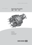
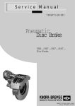
Commercial Vehicle Systems
Service Manual
Air Disc Brake
SB6 - SB7 - Axial and Radial Disc Brake
Index
Page
1
1.1
1.2
1.2.1
1.3
1.4
1.4.1
1.5
Overview
Axial Disc Brake Components.............................................................................
Axial Disc Brake Identification and Service Kits...................................................
Axial Disc Brake Wear Indicator Kits ..................................................................
Radial Disc Brake Components..........................................................................
Radial Disc Brake Identification and Service Kits ...............................................
Radial Disc Brake Wear Indicator Kits ................................................................
Brake Disc..........................................................................................................
4
5
5
6
7
7
8
2
2.1
2.2
2.3
2.4
General Information
(for Axial and Radial Disc Brakes)
Service Tools......................................................................................................
Diagnostic Equipment.........................................................................................
Lubrication..........................................................................................................
Torque Requirements.........................................................................................
9
9
9
9
3
3.1
3.2
3.2.1
3.2.2
3.2.3
3.3
3.4
3.4.1
3.4.2
3.4.3
Description and Function
Axial Disc Brake Sectioned View.........................................................................
Description of Operation.....................................................................................
Brake Actuation..................................................................................................
Brake Release.....................................................................................................
Brake Adjustment (automatic).............................................................................
Radial Disc Brake Sectioned View......................................................................
Description of Operation.....................................................................................
Brake Actuation..................................................................................................
Brake Release....................................................................................................
Brake Adjustment (automatic).............................................................................
10
11
11
11
11
12
13
13
13
13
4
4.1
Inspection Points for the Axial and Radial Disc Brake .................................
Safety Instructions for Service Work and Repair Work........................................
(for Axial and Radial Disc Brakes)
5
Functional and Visual Checks
(for Axial and Radial Disc Brakes)
Wear Check of Pads and Brake Discs................................................................
Brake Wear Check using Rubber Bush (6a, 6d)..................................................
Brake Wear Check using Rubber Bush (6b)........................................................
Brake Wear Check using Rubber Bush (6c, axially ribbed)..................................
Wear Indicators...................................................................................................
Diagnostic Equipment - Hand held device ZB9031-2.........................................
Adjuster Check...................................................................................................
Version without Shear Adapter (61).....................................................................
Version with Shear Adapter (61)..........................................................................
Caliper Checks...................................................................................................
Caliper Running Clearance..................................................................................
Caliper Movement along Guide Pins...................................................................
Rubber Bush to Guide Pin Clearance.................................................................
Check of Seals....................................................................................................
Caliper Guide Pin Seals.......................................................................................
Check of Tappet and Boot Assembly (13)..........................................................
16
18
19
20
21
21
22
22
23
25
25
25
25
27
27
27
Pad Replacement
(for Axial and Radial Disc Brakes)
Pad Removal .....................................................................................................
Version without Shear Adapter (61).....................................................................
Version with Shear Adapter (61)..........................................................................
Pad Fitting..........................................................................................................
Wear Indicator Fitting (Normally Closed or Normally Open Type).........................
Cable Guide Type (105)......................................................................................
Cable Guide Type (105a).....................................................................................
Protection Plate (104).........................................................................................
28
28
29
30
31
32
32
32
5.1
5.1.1
5.1.2
5.1.3
5.1.4
5.1.5
5.2
5.2.1
5.2.2
5.3
5.3.1
5.3.2
5.3.3
5.4
5.4.1
5.4.2
6
6.1
6.1.1
6.1.2
6.2
6.3
6.3.1
6.3.2
6.3.3
2
14
15
7
7.1
7.1.1
7.2
7.3
8
8.1
8.2
8.2.1
8.2.2
8.2.3
8.2.4
Replacement of Tappet and Boot Assemblies (13) as well as Inner Seals (22)
(for Axial and Radial Disc Brakes)
Tappet and Boot Assemblies (13) Removal...........................................................
Threaded Tubes (16) Inspection............................................................................
Inner Seals (22) Replacement................................................................................
Tappet and Boot Assemblies (13) Fitting...............................................................
33
34
34
35
Caliper Replacement
(for Axial and Radial Disc Brakes)
Caliper Removal...................................................................................................
Caliper Fitting.......................................................................................................
Fitting of Caliper (1) to Carrier (2)..........................................................................
Fitting of Outer Boot (10)......................................................................................
Fitting of Steel Cap (10a)......................................................................................
Fitting of Cap (68).................................................................................................
37
38
38
39
39
40
9
Replacement of Inner Boot (9) ..........................................................................
(for Axial and Radial Disc Brakes)
10
Guide Pin Bush Replacement
(for Axial and Radial Disc Brakes)
Brass Bush (7) Replacement.................................................................................
Rubber Bush (6a or 6b) Replacement...................................................................
Rubber Bush (6c or 6d) Replacement...................................................................
Removal of Rubber Bush (6c or 6d)......................................................................
Fitting of Rubber Bush (6c or 6d)..........................................................................
10.1
10.2
10.3
10.3.1
10.3.2
11
Carrier Replacement ..........................................................................................
(for Axial and Radial Disc Brakes)
12
Brake Actuator Replacement
(for Axial and Radial Disc Brakes)
Brake Chamber Removal......................................................................................
Brake Chamber Fitting .........................................................................................
Spring Brake Removal..........................................................................................
Spring Brake Fitting..............................................................................................
12.1
12.2
12.3
12.4
41
43
44
44
45
45
46
47
47
48
48
PLEASE NOTE
This Service manual is intended for the exclusive use of trained persons within the commercial vehicle industry
and workshops, and must not be passed to any third party.
This service manual has been prepared to assist customers to carry out their own service work on the product
and does not purport to be all-inclusive or to contain all of the information necessary for this. No responsibility
is assumed as a result of this or as a result of incorrect or inappropriate parts being fitted to the product.
Knorr-Bremse SFN cannot accept any nor offer any guarantee regarding data accuracy, completeness or
timeliness. The information in this service manual does not represent any guarantees or ensured
characteristics in terms of the German civil code.
No liability can be accepted based on the information, its use, recommendations or advice provided within this
service manual. In no event may we be held liable for any damage or loss except in the case of wilful intent or
gross negligence on our part, or if any mandatory legal provisions apply.
Brand names mentioned in this service manual are not identified as such in all cases. We would emphasise
however, that they are nevertheless subject to the provisions of trademark legislation.
Text and graphics created by us are subject to our regulations on utilisation and exploitation and may only be
copied or reproduced with our express permission.
Any legal disputes arising from the use of this service manual or the information contained within shall be
subject to German law.
Failure of any individual clause of this disclaimer to comply with current legal provisions does not affect the
validity of the remaining clauses.
This disclaimer is an English translation of a German text, which should be referred to for all legal purposes.
3
1
Overview
1.1 Axial Disc Brake Components
(for Wear Indicators see Section 1.2.1)
11
44
26
45
18/1
4d*)
18/2
Weißes Montagefett
White assembly grease
12/2
4c*)
4b*)
Grünes Montagefett
Green assembly grease
12/1
4a*)
12
6d*)
1
13
6b*)
39d*)
6c*)
37
39c*)
6a*)
68*)
39b*)
39a*)
61*)
37a*)
7
161
22
5
5a*)
9
58
Weißes Montagefett
White assembly grease
40a*)
40
10*)
31a *)
mikroverkapselt
)
10a *
pre-applied adhesive
1
2
4a*)
4b*)
4c*)
4d*)
5
5a*)
6a*)
6b*)
6c*)
6d*)
7
9
10
10a*)
11
12
12/1
12/2
13
4
Caliper
Carrier
Guide Pin
Guide Pin
Guide Pin
Guide Pin
Guide Pin
Guide Pin
Rubber Bush
Rubber Bush
Rubber Bush
Rubber Bush
Brass Bush
Inner Boot
Outer Boot
Steel Cap
Pad Retainer (reinforced)
Pad (complete)
Pad
Pad Holder Spring
Tappet and Boot Assembly
18/1
18/2
22
26
31
31a*)
37
37a*)
39a*)
39b*)
39c*)
39d*)
40
40a*)
44
45
58
61*)
68*)
161
Spring Brake
Brake Chamber
Inner Seal
Spring Clip
Outer Boot Clip
O-Ring
Adjuster Cap
Adjuster Cap
Caliper Bolt
Caliper Bolt
Caliper Bolt
Caliper Bolt
Caliper Bolt
Caliper Bolt
Pad Retainer Pin
Washer
Ring
Shear Adapter
Cap
Tappet Bush
2
FD00249/1
31*)
*) Variants
See also contents leaflet in the Service Kit
1.2
Axial Disc Brake Identification and Service Kits
Type of Caliper
Knorr-Bremse Part No.
Axle-or Vehicle
Manufacturer`s No.
Date of Manufacture
ATTENTION!
Use only genuine Knorr-Bremse parts!
The following Service Kits are available :
Description
Contents
Carrier
Guide Pins and Seal Kit
Set for Rubber Bush
Tappet and Boot Kit (2 pieces)
Set for Outer Boot and Steelcap (6 pieces)
Adjuster Cap (10 pieces)
Pad Kit (per axle)
Wear Indicator Kit (per axle)
Exchange Caliper r.h.
2
4a*), 5, 6a*), 7, 9, 10*), 31*), 39a*), 40, For specific Service Kit Part
58, (4b*), 4c*), 4d*), 5a*), 6b*), 6c*), Numbers for each Disc Brake,
6d*), 10a*), 31a*), 39b*), 39c*), 39d*),
see Disc Brake Product
40a*), 68*))
Catalogue (Part
4a*), 6a*), 39a*), (4b*), 6b*), 39b*))
Number Y000875)
13, 22, 161
10, 31, 10a*), 31a*)
or
37, 37a*), 61*)
www.knorr-bremsesfn.com
11, 12, 26, 37, 37a*), 44, 45, 61*)
see section 1.2.1
Exchange Caliper l.h.
only in assembled condition
see Identification Plate
on the Caliper
*)
1.2.1 Axial Disc Brake Wear Indicator Kits
Variants
Type 4
Type 1
Type 2
105a
FD00306
Type 5
Alternative to
Item 105
Type 3
Type 6
101
102
104
105
105a
112
Sensor
Sensor
Cable Protection Plate
Cable Guide
Cable Guide
Clip
115
116
117
119
120
Spring Washer
Screw
Wear Indicator Cable
Bracket
Bracket
5
1.3 Radial Disc Brake Components
(for Wear Indicators see 1.4.1)
18/1
11
18/2
44
26
45
4d*)
Weißes Montagefett
White assembly grease
4c*)
4b*)
12/2
4a*)
12/1
Grünes Montagefett
Green assembly grease
12
6d*)
13
6b*)
39d*)
6c*)
37
39c*)
6a*)
37a*)
68*)
39b*)
39a*)
61*)
7
161
22
5
5a*)
9
58
Weißes Montagefett
White assembly grease
40a*)
40
1
2
4a*)
4b*)
4c*)
4d*)
5
5a*)
6a*)
6b*)
6c*)
6d*)
7
9
10
10a*)
11
12
12/1
12/2
13
6
10
31a *) mikroverkapselt
)
10a *
pre-applied adhesive
Caliper
Carrier
Guide Pin
Guide Pin
Guide Pin
Guide Pin
Guide Pin
Guide Pin
Rubber Bush
Rubber Bush
Rubber Bush
Rubber Bush
Brass Bush
Inner Boot
Outer Boot
Steel Cap
Pad Retainer (reinforced)
Pad (complete)
Pad
Pad Holder Spring
Tappet and Boot Assembly
18/1
18/2
22
26
31
31a*)
37
37a*)
39a*)
39b*)
39c*)
39d*)
40
40a*)
44
45
58
61*)
68*)
161
Spring Brake
Brake Chamber
Inner Seal
Spring Clip
Outer Boot Clip
O-Ring
Adjuster Cap
Adjuster Cap
Caliper Bolt
Caliper Bolt
Caliper Bolt
Caliper Bolt
Caliper Bolt
Caliper Bolt
Pad Retainer Pin
Washer
Ring
Shear Adapter
Cap
Tappet Bush
2
VF00113/2-Äi05
31
*) Variants
See also contents leaflet in the Sevice Kit
1.4
Radial Disc Brake Identification and Service Kits
Type of Caliper
Knorr-Bremse Part No.
Axle-or Vehicle
Manufacturer`s No.
Date of Manufacture
ATTENTION!
Use only genuine Knorr-Bremse parts!
The following Service Kits are available :
Description
Contents
Carrier
Guide Pins and Seal Kit
Set for Rubber Bush
Tappet and Boot Kit (2 pieces)
Set for Outer Boot and Steelcap (6 pieces)
Adjuster Cap (10 pieces)
Pad Kit (per axle)
Wear Indicator Kit (per axle)
Exchange Caliper r.h.
2
4a*), 5, 6a*), 7, 9, 10*), 31*), 39a*), 40, For specific Service Kit Part
58, (4b*), 4c*), 4d*), 5a*), 6b*), 6c*), Numbers for each Disc Brake,
6d*), 10a*), 31a*), 39b*), 39c*), 39d*),
see Disc Brake Product
40a*), 68*))
Catalogue (Part
4a*), 6a*), 39a*), (4b*), 6b*), 39b*))
Number
Y000875)
13, 22, 161
10, 31, 10a*), 31a*)
or
37, 37a*), 61*)
www.knorr-bremsesfn.com
11, 12, 26, 37, 37a*), 44, 45, 61*)
see section 1.2.1
Exchange Caliper l.h.
only in assembled condition
see Identification Plate
on the Caliper
*)
1.4.1 Radial Disc Brake Wear Indicator Kits
Variants
Type 4
Type 1
Type 2
105a
FD00306
Type 5
Alternative to
Item 105
Type 3
Type 6
101
102
104
105
105a
112
Sensor
Sensor
Cable Protection Plate
Cable Guide
Cable Guide
Clip
115
116
117
119
120
Spring Washer
Screw
Wear Indicator Cable
Bracket
Bracket
7
1.5 Brake Disc
(for Axial and Radial Disc Brakes)
When replacing the Discs, please refer to the instructions of the Vehicle Manufacturer.
This should also be done when fitting Knorr-Bremse Brake Discs.
When replacing Discs, please adhere to the recommended bolt tightening torques.
The use of non-approved Brake Discs will reduce levels of safety and invalidate warranty.
Brake Discs can be ordered through the Knorr-Bremse Aftermarket Organisation.
Detailed information can be found in our Disc Brake Product Catalogue (Part Number Y000875) or
at www.knorr-bremsesfn.com.
8
2
General Information
(for Axial and Radial Disc Brakes)
2.1 Service Tools
Part Number
Description
ll19252
Press-in Tool for Tappet and Boot Assembly (13)
ll19253
Pull-in Tool for Inner Boot (9)
ll19254
Pull-in/Pull-out Tool for Brass Bush (7)
II32202
Wedged Fork for removal of Tappet and Boot Assembly (13)
II36797
Grooving Tool for Brass Bush (7)
Z001105
Press-in Tool for Steel Cap (10a)
Z004198
Pull-in/Pull-out Tool for Rubber Bush (6c) and (6d)
Z003934
Press-in Tool for Cap (68)
Z004361
Press-in Tool for Inner Seal (22)
Service tool kit ZB9032 (Part No. II37951004EN) contains the above listed tools for
items 7, 9, 10a, and 13 as well as this Service manual and a service video. The service
video in English is available separately in the UK as Part No. KBP2060/1 and in other
territories as B98283EN.
The tools for items 6c, 6d, 22 and 68 are not part of the Service Tool Kit ZB9032
(Part No. II37951004EN)
2.2 Diagnostic Equipment
Part Number
Description
ZB9031-2 hand held device for checking
Potentiometer function (also Pad plus Disc
ll40598F
wear) when 13 pin chassis plug installed.
ZB9031-2 replaces ZB9031
2.3 Lubrication
Part Number
Colour
Quantity
ll14525
white
5g
II32793
green
8g
ll32868
white
500g
Z000046
green
500g
Important Note: The correct grease MUST be used for each Bush !
2.4 Torque Requirements
Item Number
Torque
Spanner Size
(mm)
39a; 39b; 39c;
Caliper Bolts (x2)
180 Nm
39d; 40; 40a;
M16x1,5 - 10.9
plus 90°
14
Brake Chamber, Spring Brake
Hexagon Nuts M16x1,5 (x2)
(self-locking) EN ISO 10531
180
+30
Nm
24
9
3
Description and Function
3.1
1
2
4b*)
5*)
6b*)
6c*)
7
9
10*)
10a*)
11
12
13
16
17
18/1
18/2
19
20
22
23
24
26
27
28
30
31
31a*)
32
33
37
37a*)
39b*)
40*)
43
44
45
46
61*)
68*)
161
10
Axial Disc Brake Sectioned View
Caliper
Carrier
Guide Pin
Guide Pin
Rubber Bush
Rubber Bush
Brass Bush
Inner Boot
Outer Boot
Steel Cap
Pad Retainer (reinforced)
Pad (complete)
Tappet and Boot Assembly
Threaded Tube
Bridge
Spring Brake
Brake Chamber
Lever
Eccentric Bearing
Inner Seal
Adjuster Unit
Turning Device
Spring Clip
Spring
Spring
Chain
Outer Boot Clip
O-Ring
Chain Wheel
Wear Sensor
Adjuster Cap
Adjuster Cap
Caliper Bolt
Caliper Bolt
Bolt
Pad Retainer Pin
Washer
Disc
Shear Adapter
Cap
Tappet Bush
*) Variants
3.2 Description of Operation
(Floating Caliper principle)
3.2.1
Brake Actuation
During actuation, the Push Rod of the Actuator (18/1
or 18/2) moves the Lever (19). The input forces are
transferred via the Eccentric Bearing (20) to the
Bridge (17). The force is then distributed by the
Bridge (17) and the two Threaded Tubes (16) to the
Tappet and Boot Assemblies (13) and finally to the
inboard Pad (12).
After overcoming the running clearance between the
Pads and the Disc, the reaction forces are
transmitted to the outboard Pad (12). The clamping
forces on the Pads (12) and the Disc (46) generate
the braking force for the wheel.
3.2.2. Brake Release
After releasing the air pressure, the two Return
Springs (27/28) push the Bridge (17) and Lever (19)
back to the start position; this ensures a running
clearance between Pads and Disc is maintained.
3.2.3
Brake Adjustment (automatic)
To ensure a constant running clearance between
Disc and Pads, the brake is equipped with a low
wearing, automatic adjuster mechanism.
The Adjuster (23) operates with every cycle of
actuation due to the mechanical connection with
Lever (19). As the Pads and Disc wear, the running
clearance increases. The Adjuster (23) and Turning
Device (24) turn the Threaded Tubes (16) by an
amount necessary to compensate for this wear. The
total running clearance (sum of clearance both sides
of Disc) should be between 0.5 and 1.0 mm.; smaller
clearances may lead to overheating problems.
11
3.3
Radial Disc Brake Sectioned View
31a*)
9
7
31 10
5*) 40*)
161
10a*)
16
24
22
33
44
32
26
45
61*)
11
12
Guide Pin
Rubber Bush
Rubber Bush
Brass Bush
Inner Boot
Outer Boot
Steel Cap
Pad Retainer (reinforced)
Pad (complete)
Tappet and Boot Assembly
Threaded Tube
Bridge
Spring Brake
Brake Chamber
Lever
Eccentric Bearing
Inner Seal
Adjuster Unit
Turning Device
Spring Clip
Spring
Spring
Chain
Outer Boot Clip
O-Ring
Chain Wheel
Wear Sensor
Adjuster Cap
Adjuster Cap
Caliper Bolt
Caliper Bolt
Bolt
Pad Retainer Pin
Washer
Disc
Shear Adapter
Cap
Tappet Bush
30
17
37
43
37a*)
23
1
68*)
2
13 39b*) 4b*) 6b* )
6c* )
VF 00113/3-Äi03
6b*)
6c*)
7
9
10*)
10a*)
11
12
13
16
17
18/1
18/2
19
20
22
23
24
26
27
28
30
31
31a*)
32
33
37
37a*)
39b*)
40*)
43
44
45
46
61*)
68*)
161
Caliper
Carrier
Guide Pin
12
27; 28 20
19
18/1; 18/2
46
VF 00113/4
1
2
4b*)
5*)
*) Variants
3.4 Description of Operation
(Floating Caliper principle)
3.4.1.
Brake Actuation
During actuation, the Push Rod of the Actuator (18/1
or 18/2) moves the Lever (19). The input forces are
transferred via the Eccentric Bearing (20) to the
Bridge (17). The force is then distributed by the
Bridge (17) and the two Threaded Tubes (16) to the
Tappet and Boot Assemblies (13) and finally to the
inboard Pad (12).
After overcoming the running clearance between the
Pads and Disc, the reaction forces are transmitted to
the outboard Pad (12). The clamping forces on the
Pads (12) and the Disc (46) generate the braking
force for the wheel.
3.4.2. Brake Release
After releasing the air pressure, the two Return
Springs (27/28) push the Bridge (17) and Lever (19)
back to the start position; this ensures a running
clearance between Pads and Disc is maintained.
3.4.3
Brake Adjustment (automatic)
To ensure a constant running clearance between
Disc and Pads, the brake is equipped with a low
wearing, automatic adjuster mechanism. The
Adjuster (23) operates with every cycle of actuation
due to the mechanical connection with Lever (19). As
the Pads and Disc wear, the running clearance
increases. The Adjuster (23) and Turning Device (24)
turn the Threaded Tubes (16) by an amount
necessary to compensate for this wear. The total
running clearance (sum of clearance both sides of
Disc) should be between 0.5 and 1.0 mm.; smaller
clearances may lead to overheating problems.
13
4
Inspection Points for the Axial and Radial Disc Brake
Despite the use of long-life materials, it is necessary to check some of the components regularly for their
general condition. The following points ensure a long-life and trouble-free operation of the disc brake. The
inspection frequencies specified are minimum values. Depending on the vehicle application a more frequent
check of the components may be necessary.
The brake pad wear must be checked visually on a regular basis, e.g. each time the tyre pressures are
checked, or at least every three months (see Sections 5.1.1, 5.1.2, 5.1.3).
At least annually inspect the pad to disc running clearance and the correct fitting and condition of the Outer
Boot (10) or Steel Cap (10a) and the Adjuster Cap (37 or 37a) (see Section 5.3.1).
With each Pad change check for the correct functioning of the Adjuster (see Section 5.2) and the smooth
operation of the caliper over its full range of movement (see Section 5.3.2). Also inspect the Tappet and
Boot Assemblies (13), the Adjuster Cap (37 or 37a) and the sealing elements (6c, 9, 10, 10a, 31, 58, 68)
for correct fitting and condition.
The brake discs are to be checked according to the specification of the axle or vehicle manufacturer.
In the unlikely event of a problem, all relevant components - e.g. Pads (12/1) and Pad Holder
Springs (12/2) - must be returned in order that an objective investigation of the cause can be made.
11
44
26
45
18/1
4d*)
18/2
Weißes Montagefett
White assembly grease
12/2
4c*)
Grünes Montagefett
Green assembly grease
4b*)
12/1
4a*)
12
6d*)
1
13
6b*)
39d*)
6c*)
37
39c*)
6a*)
68*)
39b*)
39a*)
61*)
37a*)
7
161
22
5
5a*)
9
58
Weißes Montagefett
White assembly grease
40
31*)
40a*)
10*)
2
FD00249/1
31a *)
mikroverkapselt
10a *)
pre-applied adhesive
14
4.1 Safety Instructions for Service Work and
Repair Work
(for Axial and Radial Disc Brakes)
Please also refer to the relevant safety instructions for
repair work on commercial vehicles, especially for
jacking up and securing the vehicle.
Use only original Knorr-Bremse parts.
ATTENTION!
Before starting service work, ensure the
service brake and parking brake, as well
as the bus stop brake with buses, are not
applied and that the vehicle cannot
roll away.
Please follow service manual instructions and adhere
to the wear limits of the Pads and the Discs - see
Section 5.1.
Use only recommended tools - see Section 2.1.
Tighten bolts and nuts to the recommended torque
values - see Section 2.4.
ATTENTION!
Screw threads and tapped holes must be
clean and dry (free of lubrication).
After re-fitting a wheel according to the Vehicle
Manufacturer’s recommendations, please ensure that
there is sufficient clearance between the tyre inflation
valve, the caliper and the wheel rim, to avoid damage
to the valve.
After service work:
Check the brake performance and the system
behaviour on a rolling road.
15
5
Functional and Visual Check
(for Axial and Radial Disc Brakes)
5.1 Wear Check of Pads and Brake Discs
ATTENTION!
For optimum safety, stay within the Disc and Pad Wear Limits.
Sketch 1
Pads
The thickness of the Pads must be checked regularly
dependent on the usage of the vehicle.
The Pads should be checked corresponding to any
legal requirements that may apply.
If a Wear Indicator has not been fitted or is not
connected, this should be at least every 3 months.
If friction material is less than 2mm (see E, Sketch 3),
the Pads must be replaced.
Minor damage at the edges is permitted (see arrow,
Sketch 1).
Sketch 2
Major damage on the surface of the Pad is not
permitted (see arrow, Sketch 2).
Discs
Sketch 3
A = Disc thickness
new condition = 45 mm
worn condition = 37 mm (must be replaced)
C = Overall thickness of Pad (new condition) 30mm
D = Backplate 9mm
E = Minimum thickness of friction material 2mm
F = Minimum allowed thickness in worn condition
for backplate and friction material 11mm
(replacement of Pads necessary).
C
A
D
If the disc dimension A ≤ 39 mm, it is
recommended that the Disc should be renewed
together with the Pads.
ATTENTION!
If these recommendations are ignored, there is a danger of brake failure.
16
E
F
M+P-KN-002Äi01
Measure thickness at thinnest point. Avoid measuring
near the edge of the disc as a burr may be present.
A1
B1
a
Check Disc at each change of Pads for grooves and
cracks.
max. 0,75 x a
max. 1,5 mm
The diagram shows possible surface conditions.
A1 = Small cracks spread over the surface
are allowed
B1 = Cracks less than 1.5mm deep or wide, running
in a Radial direction are allowed
D1
C1 = Grooves (circumferencial) less than 1.5mm
deep are allowed
C1
A
VF 00127/3/Äi01
D1 = Cracks in the vanes are not allowed and the
Disc MUST BE REPLACED.
a = Pad contact area
Note:
In case of surface conditions A1, B1 and C1, the Disc
can continue to be used until the minimum
thickness A of 37mm is reached.
Knorr-Bremse Discs are normally service-free and
grinding when changing Pads is not necessary.
However, grinding could be useful, e.g. to increase
the load-bearing surface of the Pads after severe
grooving on the entire friction surface has occurred.
To meet safety requirements, the minimum thickness
after regrinding must be greater than 39 mm.
In addition, the recommendations of the Vehicle
Manufacturer MUST be followed.
ATTENTION!
If these recommendations are ignored, there is a danger of brake failure. If the Pads
are worn down to the backplate or if Disc wear is excessive, brake
performance will be severely affected and may be lost completely.
17
5.1.1 Brake Wear Check using Rubber Bush (6a; 6d): For all Axial and Radial Disc Brakes except
those listed in Section 5.1.2 and 5.1.3. These Calipers do not have a cast rib in position B (see also
Section 5.1.2)
C
4a/4d
4a/4d
6a/6d
6a/6d
B
The condition of the Pads can be visually determined
without removing the road wheel by viewing the
position of the Guide Pin (4a or 4d) in the Caliper (1).
If dimension ‘C’ is less than 1mm, a more accurate
check of the Pads and Disc must be made.
If necessary change the Pads - see Section 6, or the
Disc - see Vehicle Manufacturer’s recommendations.
18
1
D
M+P-KN-005Äi01
1
B = without rib (see also Section 5.1.2)
C = pin protrusion - shown in new condition
D = 1 mm or less - Pads and Disc must be checked
with road wheel removed
5.1.2 Brake Wear Check using Rubber Bush (6b): Only for Axial Disc Brakes SB 7541,
SB 7551 to SB 7629, SB 7639 and Radial Disc Brakes SB 7102, SB 7112, SB 7103, SB 7113,
SB 7104, SB 7114, SB 7105, SB 7115, SB 7108, SB7118, SB 7109, SB 7119, SB 7120, SB 7130.
These Calipers do have a cast rib in position B (see also Section 5.1.1)
1
4b
4b
6b
6b
B
C
D
The condition of the Pads can be visually determined
without removing the road wheel by viewing the
position of the Guide Pin (4b) in the Caliper (1).
M+P-KN-006Äi01
1
B = with rib (see also Section 5.1.1)
C = new condition
D = 18 mm or more, Pads and Disc must be
checked with road wheel removed
If the head of the Guide Pin (4b) is inside the Rubber
Bush (6b) by a dimension D greater than 18mm, then
a more accurate check of the Pads and Disc must
be made.
If necessary change the Pads - see Section 6, or the
Disc - see Vehicle Manufacturer’s recommendations.
19
5.1.3 Brake Wear Check using Rubber Bush (6c, axially ribbed): For all Axial and Radial Disc Brakes
which are equiped with a Rubber Bush that is axially ribbed (see H in sketch).
1
1
4c
4c
G
6c
6c
"X"
G "Z"
The condition of the Pads can be visually
determined without removing the road wheel, by
viewing the position of the Wear Indicator “G”.
New Condition
(see “X”)
The position of Wear Indicator “G” on the Rubber
Bush (6c) in new condition.
20
FD00190/1Äi02
H
Wear Limit
(see “Z”)
When the Rubber Bush (6c) is retracted to the level
“G” of the Wear Indicator as shown, the wheel must
be removed so that the wear of the Pads and Disc
can be checked.
If necessary change the Pads - see Section 6 or the
Disc - see Vehicle Manufacturer’s recommendations.
5.1.4 Wear Indicators
Due to different Vehicle Manufacturer and vehicle
types there are several types of Pad Wear Indicator
used.
a)
M+P-KN-007
b)
In-pad Normally Closed Indicator - Circuit is
broken when Pad Wear reaches limit.
In-pad Normally Open Indicator - Circuit is
made when Pad Wear reaches limit.
c)
Wear Indicator using built in Potentiometer. This
is available either as an on/off version or
as a continuous signal version which can be
linked to the vehicle’s electronic monitoring
systems.
An optical or acoustic device may be linked to any of
the above.
M+P-KN-008
Note:
Please also refer to specifications provided by the
Vehicle Manufacturer.
5.1.5
Diagnostic Equipment
The Knorr-Bremse Diagnostic Unit ZB9031-2 is a
hand held device suitable for vehicles that are fitted
with Knorr-Bremse Disc Brakes using a continuous
signal type of Wear Indicator Potentiometer.
The wear condition of each brake can be measured
by connecting the device to a suitable 13 pin socket
(DIN 72570) where fitted. This socket will have
been connected to each sensor by the vehicle
manufacturer.
The Diagnostic unit allows:
Quick and simple wear check.
A check of the potentiometer function.
A simultaneous check of up to six brakes,
without removing the wheels.
13-Pin Plug
(DIN 72570)
to Vehicle
Plug to Potentiometer
(Disc Brake)
A detailed instruction manual is included with
each unit.
21
5.2 Adjuster Check
5.2.1 Version without Shear Adapter (61)
ATTENTION!
Before starting service work, ensure the
service brake and parking brake, as well
as the bus stop brake with buses, are not
applied and that the vehicle cannot
roll away.
23
M+P-KN-039/Äi01
37
Remove wheel.
The caliper assembly should be pushed inboard on
its Guide Pins. Using a suitable tool, press the
inboard pad (12) away from the Tappets and check
the gap between Tappet and inboard pad backplate
- it should be between 0.5mm & 1.0mm. If the
running clearance is too small or large, the adjuster
may not be functioning correctly and should be
checked as follows.
Remove Adjuster Cap (37).
23
ATTENTION!
37
1
M+P-KN-015/Äi01
Do not overload or damage the Adjuster
(23). Use only 8mm Ring Spanner or 1/4”
drive Socket with a lever length no greater
than 100mm. A maximum torque of
25 Nm is admissible.
DO NOT use an Open Ended Spanner
since this may damage the Adjuster shaft.
The Adjuster should be turned anti-clockwise for
3 clicks (increasing running clearance).
ATTENTION!
By applying the brake (to at least 2 Bar) 5 - 10 times
the Spanner or Socket should turn clockwise in small
increments if the Adjuster is functioning correctly
(see notes below).
NOTE:
As the number of applications increases, incremental
movement will decrease.
NOTE:
If the Spanner or Socket does not turn or turns only
with the first application or turns forward and
backward with every application, the automatic
Adjuster has failed and the Caliper must be replaced.
Even if Pads are not being changed, a new Adjuster
Cap (37) should be fitted having lightly greased it with
white grease (available as Part No. II14525 or
II32868).
22
M+P-KN-043
Make sure that the Ring Spanner or
Socket can turn freely clockwise
during following procedure.
5.2.2 Version with Shear Adapter (61)
ATTENTION!
Before starting service work, ensure the
service brake and parking brake, as well
as the bus stop brake with buses, are not
applied and that the vehicle cannot
roll away.
61 37a
FD00150/1
Remove wheel.
The caliper assemply should be pushed inboard on
its Guide Pins. Using a suitable tool, press the
inboard pad (12) away from the Tappets and check
the gap between Tappet and inboard pad backplate
- it should be between 0.5mm & 1.0mm. If the
running clearance is too small or large, the adjuster
may not be functioning correctly and should be
checked as follows.
Pull off the Adjuster Cap (37a) using the tag, taking
care not to lose the Shear Adapter (61).
The Adjuster (23) must be turned with the Shear
Adapter (61) anti-clockwise for 3 clicks
(increasing running clearance).
23
61 37a
Never turn Adjuster (23) without Shear
Adapter (61) being fitted. If the given
shear torque of the Shear Adapter is
exceeded, then it is destroyed. Try with a
new (unused) Shear Adapter. With a
second failure of the Shear Adapter the
Caliper must be exchanged since internal
damage is present. Do not use an open
ended spanner, because it may damage
the Shear Adapter (61).
1
FD00151/1
ATTENTION!
ATTENTION!
Make sure that the Ring Spanner or
Socket can turn freely clockwise
during following procedure.
NOTE:
As the number of applications increases, incremental
movement will decrease.
NOTE:
If the Spanner or Socket does not turn or turns only
with the first application or turns forward and
backward with every application, the automatic
Adjuster has failed and the Caliper must be replaced.
M+P-KN-043
By applying the brake (to at least 2 Bar) 5 - 10 times
the Spanner or Socket should turn clockwise in small
increments if the Adjuster is functioning correctly
(see notes below).
23
Note:
The tag of the Adjuster Cap (37a) should be
positioned as shown by the arrow in the adjacent
diagram. This ensures access is maintained for
subsequent removal. Removal of the Adjuster Cap
with e.g. a screwdriver is not recommended since
the seal may be damaged.
24
37a
FD00144/1
Even if Pads are not being changed, a new Adjuster
Cap (37a) should be fitted having lightly greased it
with white grease (available as Part No. II14525 or
II32868).
5.3
Caliper Checks
5.3.1 Caliper Running Clearance
31a* )
ATTENTION!
Before starting service work, ensure the
service brake and parking brake, as well
as the bus stop brake with buses, are not
applied and that the vehicle cannot
roll away.
10a* )
9 5*) 7
10
By pushing and pulling the Caliper in an axial
direction by hand (see arrow A in adjacent sketch), a
movement of 0,5 - 1.0 mm must possible.
If using hand pressure only (no tools) the Caliper is
not movable, the Caliper guidance must be further
examined (see Section 5.3.2).
5.3.2 Caliper Movement along Guide Pins
Remove Pads (see Section 6.1)
Clean dirt from Guide Pin (4a, 4b, 4c, 4d) (see arrows
in Sketch).
Using hand pressure only (no tools), the Caliper (1)
must slide freely along the whole length of the Guide
Pin arrangement. This movement should be greater
than 25mm.
1
5.3.3 Rubber Bush to Guide Pin Clearance
Note:
Before removing the wheel, note that there is no
contact between Caliper and axle, vehicle, chassis
sections or Carrier. If necessary the Rubber Bush
(6a, 6b, 6c, 6d), must be replaced (see Section 10.2,
10.3).
A
*) Pay attention to the variants
68*)
6c* )
M+P-KN-013-Äi03
4b* ) 6b*)
To measure the clearance, the following steps must
be taken:
Remove the wheel. Refer to Vehicle Manufacturer’s
recommendations.
Fully wind-back the Tappet and Boot Assemblies (13)
by rotating the Adjuster (23) in an anti-clockwise
direction (see Section 5.2.1, 5.2.2).
Slide Caliper as far as possible towards the outside
of the vehicle (see Sketch 1).
Sketch 1
FD00196/6
Remove Pads (see Section 6.1).
25
Push the Caliper in the direction of the arrow (see
Sketch 2).
Note that there is no contact between Caliper and
axle, vehicle, chassis sections or Carrier. If
necessary the Rubber Bush (6a, 6b, 6c, 6d), must be
replaced (see Section 10.2 and 10.3).
X
Whilst maintaining pressure on the Caliper, measure
the distance ‘x’ (see Sketch 2).
If the distance (y-x) is greater than 3mm, the Rubber
Bush (6a, 6b, 6c, 6d) must be replaced (see Section
10.2 and 10.3).
FD00196/4
Pull the Caliper away from the Carrier and measure
distance ‘y’ (see Sketch 3).
Sketch 2
Fit Pads (see Section 6.2).
Sketch 3
26
FD00196/5
Y
Fit the wheel. Refer to Vehicle Manufacturer’s
recommendations.
5.4 Check of Seals
5.4.1 Caliper Guide Pin Seals
31a* )
The Guide Pin (5, 5a ) is sealed with the Inner Boot
(9) and the Adjuster Cap (10) or the Steel Cap (10a)
and the O-Ring (31a). The items (9) and (10) or (10a)
must not show signs of cracking or damage. On versions with Rubber Bush (6c) this is also to be
checked for damage.
10a* )
9 5*) 7
10
Check for correct location and fitment.
Note:
It may be necessary to remove the Pads to inspect
the Inner Boot (9) - dependant on the amount of pad
wear.
If necessary repair Caliper with suitable Service Kit
(see Section 1.2 or 1.4).
4b*) 6b*)
1
68*)
If necessary remove Pads (12) (see Section 6.1) and
screw the Adjuster (23) clockwise (see Section 5.2.1,
5.2.2) until the boots are clearly visible.
*) Pay attention to the variants
6c* )
FD00205
5.4.2 Check of Tappet and Boot Assembly (13)
Note:
The tappets should not extend more than 30 mm
(see sketch).
The Tappet and Boot Assemblies (13) must not show
any signs of damage.
13
Note:
The penetration of dirt and humidity into the brake
will lead to corrosion and impair the function of the
Disc Brake.
30
M+P-KN-012/Äi01
Check for correct location and fitment.
If necessary replace Tappet and Boot Assemblies
(see Section 7).
27
6 Pad Replacement
(for Axial- and Radial Disc Brakes)
ATTENTION!
Before starting repair work, ensure the
service brake and parking brake, as well
as the bus stop brake with buses, are not
applied and that the vehicle cannot
roll away.
6.1 Pad Removal
Remove wheel (refer to Vehicle Manufacturer’s
recommendations).
Remove Clip (26) and Washer (45), depress the Pad
Retainer (11) and remove Pin (44).
If necessary remove any in-pad wear sensor
components and discard.
44
45
11
M+P-KN-010
Note:
Before removing Pads it is strongly recommended
that the Adjuster mechanism is checked for correct
operation (see Section 5.2).
26
If the Pad Retainer (11) is corroded or damaged, it
should be replaced.
6.1.1 Version without Shear Adapter (61)
Remove Adjuster Cap (37).
Fully wind-back the Tappet and Boot Assemblies (13)
by rotating the Adjuster (23) in an anti-clockwise
direction (see Section 5.2.1).
23
ATTENTION!
Push inboard Pad (12) toward Actuator.
Pull out both Pads (12).
28
37
12
12
M+P-KN-011/Äi01
Do not overload or damage the Adjuster
(23). Use only 8mm Ring Spanner or 1/4”
drive Socket with a lever length no greater
than 100mm. A maximum torque of
25 Nm is admissible.
DO NOT use an Open Ended Spanner
since this may damage the Adjuster shaft.
6.1.2 Version with Shear Adapter (61)
Pull off the Adjuster Cap (37a) using the tab, taking
care not to lose the Shear Adapter (61).
Fully wind-back the Tappet and Boot Assembly (13)
by rotating the Adjuster (23) in an anti-clockwise
direction (see Section 5.2.2).
23
23
6137
37a
Never turn Adjuster (23) without Shear
Adapter (61) being fitted. If the given
shear torque of the Shear Adapter is
exceeded, then it is destroyed. Try with a
new (unused) Shear Adapter. With a
second failure of the Shear Adapter the
Caliper must be exchanged since internal
damage is present. Do not use an open
ended spanner, because it may damage
the Shear Adapter (61).
12
12
FD00152/1
ATTENTION!
Push inboard Pad (12) toward Actuator.
Pull out both Pads (12).
29
6.2 Pad Fitting
ATTENTION!
Pads must be changed as an axle set
and NOT individually. Use only Pads which
are permitted by the vehicle
manufacturer, axle manufacturer and disc
brake manufacturer. Failure to comply
with this may invalidate the vehicle
manufacturer’s warranty
Note:
Fully wind-back the Tappet and Boot Assemplies (13)
by rotating the Adjuster (23) in an anti-clockwise
direction (see Section 5.2.1, 5.2.2) - Do not
overload the Adjuster (23).
1
Clean the Pad abutments.
Push Caliper (1) outboard and fit the outboard Pad
(12).
Push Caliper (1) inboard and fit the inboard Pad (12).
Rotate the Adjuster clockwise until the Pads come
into contact with the Disc - Do not overload the
Adjuster (23).
M+P-KN-014
Fit new In-pad Wear Indicator kit, if appropriate (see
Section 6.3 and 1.2.1 or 1.4.1).
Install the cable so that it can not be damaged.
12
Then turn back the Adjuster 3 clicks (see Section
5.2.1, 5.2.2).
The hub should turn easily by hand after having
applied and released the brake.
37a
The Adjuster Cap (37 or 37a) must then be replaced
(use only a new Cap) having lightly greased it with
white grease (available as Part No. II14525 or
II32868).
FD00144/1
Note:
The tag of the Adjuster Cap (37a) should be
positioned as shown by the arrow in the adjacent
Sketch. This ensures access is maintained for
subsequent removal. Removal of the Adjuster Cap
with e.g. a screwdriver is not recommended since
the seal may be damaged.
After setting the Pad Retainer (11) into the groove of
the Caliper (1), it must be depressed to enable the
positioning of Pad Retainer Pin (44).
Fit washer (45) and Spring Clip (26) to the Pad
Retainer Pin (44) (use only new parts).
It is recommended that Pad Retainer Pin (44) is
installed pointing downwards (see Sketch).
Re-fit wheel according to the Vehicle Manufacturer ’s
recommendations.
44
New Pads need bedding in. Heavy or
long duration braking should initially be
avoided.
30
45
26
11
1
M+P-KN-016
ATTENTION!
6.3 Wear Indicator Fitting
(Normally Closed or Normally Open Type)
101
Remove Pads (12) - see Section 6.1.
outer Pad
Wear Indicator Kits (for SB6... / SB7...) consist of
items as shown in Section 1.2.1 and 1.4.1.
12/1
12/1
FD00237/2
Insert the Wear Indicator Cables (101) into the groove
of the Pads. The Wear Indicators snap into place in
the holes in the Pad material.
The longer end of the Wear Indicator cable (see
arrow) must be fitted in the outer Pad.
FD00237/1
Insert Pads (12/1) into the Pad abutments (see
Section 6.2).
12/1
Fit Pad Holder Springs (12/2) onto the Pads (12/1).
Pay attention to correct installation of Wear Indicator
Cable (101) (see arrows).
12/2
101
12/1
44
11
45
26
101
FD00237/4
Fit Pad Retainer (11), Pad Retainer Pin (44), Washer
(45) and Spring Clip (26) (see Section 6.2)
Pay attention to correct installation of the Wear
Indicator Cable (101) (see arrows).
FD00237/3
12/2
31
6.3.1
Cable Guide Type (105)
Fit Cable Guide (105) onto the Pad Retainer (11).
In the right position, the Cable Guide (105) snaps into
place by pressing it lightly onto the Pad Retainer (11).
FD00237/5
105
Press Wear Indicator Cable (101) into the locating
tabs of the Cable Guide (105) (see arrows A).
The short cable end of the Wear Indicator Cable
(101) must not be secured by locating tabs of the
Cable Guide (105).
According to vehicle type, install the cable loom that
leads to the electrical supply of the vehicle, in one of
the two locating tabs (see arrows B).
101
B
A
short cable end
B
Cable Guide Type (105a)
Install Indicator Cable (101) in the middle of the Pad
Retainer (11).
Insert Cable Guide (105a) at one side of the Pad
Retainer (11) (see arrow B).
Slightly press in on the other side of the Pad Retainer
(11) (see arrows A). The Cable Guide (105a) snaps
into place.
According to vehicle type, install the cable loom that
leads to the electric supply of the vehicle, in one of
the wire loop (see arrows C).
The short end of the Wear Indicator Cable (101)
must not be secured by a wire loop of the Cable
Guide (105a) (see arrows C).
105a
101
A
A
C
C
FD00305
6.3.2
FD00237/6
A
B
6.3.3 Protection Plate (104)
104
11
FD00237/7
Fit the Cable Protection Plate (104).
Pay attention to the correct position of the Cable
Protection Plate’s catch (see arrows).
Exert hand pressure to the Cable Protection Plate
(104); it will snap into place.
32
7 Replacement of Tappet and Boot
Assemblies (13) as well as
Inner Seals (22) .
(for Axial and Radial Disc Brakes)
The components of the tools are referred to by item
number for ease of reference.
Press-in Tool
arrangement for
Tappet and Boot
Assembly (13) when
Caliper is fitted on the
vehicle.
To remove the Tappet and Boot Assembly (13) use
the Wedge Fork (A) (Part No. II32203).
Press-in Tool
arrangement for
Tappet and Boot
Assembly (13) when
Caliper is removed
from the vehicle.
To fit the Tappet and Boot Assembly (13) use the
Press-in Tool (B) (Part No. II19252).
Wedge Fork (A)
To fit the Inner Seal (22), use the Press-in Tool (L)
(Part No. Z004361).
Press-in Tool (B)
Press-in Tool
arrangement for
Inner Seal (22) when
Caliper is fitted on the
vehicle.
WerkzeugPress-in Tool
arrangement for
Inner Seal (22) when
Caliper is removed
from the vehicle.
Press-in Tool (L)
7.1 Tappet and Boot Assemblies (13) Removal
Note:
It may be easier to remove the Caliper from the axle
to replace the Tappet and Boot Assemblies (13) (see
Section 8.1).
The Adjuster (23) must be screwed clockwise until
the Boots can be reached (max. 30 mm) (see
Section 7.1.1).
B
To remove the Tappet Boot from the Caliper bore, a
Screwdriver should be used to deform the Boot
location ring - see diagram.
13
13
Great care must be taken not to damage
the Sealing Seat of the Tappet Boot since
it is not a replaceable item.
See arrow X in adjacent Sketch.
30
M+P-KN-017/
Ä i02
ATTENTION!
The Tappet and Boot Assemblies (13) can be
removed from the Threaded Tubes (16) by using
Wedge Fork (A) (Part No. II32202).
A
Check Inner Seal (arrow X) and if damaged, the
Caliper must be replaced (see Section 8).
Note:
If the sealing seat of the Tappet Boot has been
damaged the caliper must be replaced (see Section
8.1).
The Inner Seal (22) must also be replaced if Tappet
and Boot Assemblies (13) have been removed (see
Section 7.2).
22 x
13
A 13
161
VF 00127/4/Äi03
Remove the old Tappet Bush (161).
33
7.1.1 Threaded Tubes (16) Inspection
Place an unworn Pad (12) into the outboard gap
to avoid overrunning of the Threaded Tubes.
12
ATTENTION!
46
For the inspection of the threads, the tubes must be
screwed out (max. 30mm) by turning the Adjuster
(23) clockwise.
If Caliper is not installed on axle, put a spacer E
(length = 70mm) into the Caliper (1) to avoid
overrunning of the Threaded Tubes (16) when
screwing them out (see adjacent Sketch). During
screwing, the threads can be checked for corrosion
damage.
In case of water ingress or corrosion, the Caliper
must be replaced (see Section 8).
70 mm
E
7.2 Inner Seals (22) Replacement
VF 00127/13
16
1
Fully wind back the Threaded Tubes (16) by turning
the Shear Adapter (61) anti- clockwise (see Section
5.2).
M+P-KN-019
16
Threaded Tubes should not overrun the
inner thread of the Bridge.
The Caliper must be replaced if
synchronisation is lost.
A
Clean area of the Inner Seal (22).
To remove the Inner Seal (22) a Screwdriver (A)
should be used - see adjacent Sketch.
The sealing face (X) for the Inner Seal
(22), as well as the Threaded Tubes (16)
must not be damaged. They cannot be
replaced (see Section 7.1).
A
22
FD00297
ATTENTION!
Clean sealing face (X) .
Fit each Inner Seal (22) onto a Threaded Tube (16).
L
With Caliper installed on axle
34
X
22
L
FD00298
Remove the Tappet Bush (161).
Position Tool (L) (Part No. Z004361) with the short
strut in the position shown.
The Tool (L) is guided over the spigot of the
Threaded Tube (16).
Fully press in the Inner Seal (22) by rotating Tool (T3)
using a spanner - see adjacent Sketch.
To check the correct fit of the Inner Seal (22), screw
out the Threaded Tubes (16) about 4-5 threads by
turning the Adjuster (23) or (according Version) with
Shear Adapter (61) clockwise.
The Inner Seal (22) must not turn.
L
With Caliper not installed on axle
The fitting sequence of Inner Seal (22) does not
change.
16
22
L
FD00299
When pressing in the Inner Seal (22) however, use
the long strut (T3+T4) for Tool (L) (Part No. Z004361)
- see page 33.
7.3 Tappet and Boot Assemblies (13) Fitting
B
With Caliper installed on axle:
Grease threads with white grease (Part No. II14525
or II32868).
161
13
Screw back Threaded Tubes (16), by turning the
Adjuster (23) or (according Version) with Shear
Adapter (61) anti-clockwise (see Section 5.2.1,
5.2.2).
Place new Tappet Bush (161) onto the spigot of the
Threaded Tube (16).
VF 00127/5-Äi01
The sealing seat in the caliper for Tappet and Boot
Assemblies (13) must be clean and free of grease.
Sketch 1
13
Place Tappet and Boot Assembly (13) onto the
Tappet Bush.
B
Using Tool (B) in reverse, the Tappet can be pressed
onto the Tappet Bush - see Sketch 2.
Sketch 2
M+P-KN-022Äi01
Use Push-in Tool (B) with the short strut (T3)
(Part No. II19252) for positioning and pressing-in the
Boot - see Sketch 1.
35
With Caliper not installed on axle
Grease threads with white grease (Part No. II14525
or II32868).
B
13
Screw back Threaded Tubes (16), by turning the
Adjuster (23) or (according Version) with Shear
Adapter (61) anti-clockwise (see Section 5.2.1,
5.2.2).
Place new Tappet Bush (161) onto the spigot of the
Threaded Tube (16).
M+P-KN-021Äi01
The sealing seat in the caliper for Tappet and Boot
Assemblies (13) must be clean and free of grease.
Sketch 3
Place Tappet and Boot Assembly (13) onto the
Tappet Bush.
Use Push-in Tool (B) with the long strut (T3+T4) (Part
No. II19252) for positioning and pressing-in the Boot,
- see Sketch 3.
13
B
Sketch 4
36
M+P-KN-023Äi01
Using the Tool (B) in reverse, the Tappet can be
pressed on to the Tappet Bush - see Sketch 4.
8 Caliper Replacement
(for Axial and Radial Disc Brakes)
To remove and to fit the Steel Cap (10a) use the
Press-in Tool (G) (Part No. Z001105).
To fit the Cap (68) the Press-in Tool (K) (Part No.
Z003934) must be used.
8.1 Caliper Removal
Remove Pads (see Section 6.1).
Remove Actuator (see Section 12.1, 12.3).
Press-in Tool (G)
Press-in Tool (K)
Disconnect Potentiometer Type Wear Indicator if
fitted.
Proceed as follows if the Caliper (1) is to be removed
from the Carrier (2), with the Carrier remaining on the
vehicle.
Remove Outer Boot Clip (31) and take off Outer Boot
(10), or on Calipers with Steel Cap (10a) and O-Ring
(31a), place tool (G) (Part No. Z001105) onto the
Steel Cap and tighten the threaded pins. Then use
hammer as shown.
10
31
10a
39
31a
31
40
10
M+P-KN-024-Äi01
Note:
It may be necessary to remove the Caliper (1) and
the Carrier (2) as a single unit, depending upon the
vehicle installation, in line with vehicle manufaturer’s
recommendations.
On Calipers with Rubber Bush (6c) pull the Cap (68)
from the Guide Pin (4c) using a suitable tool (see
Sketch).
Remove Caliper Bolts (39a, 39b, 39c or 39d) and (40
or 40a).
ATTENTION!
Before removing the Caliper Bolts (39 and
40) ensure that the Caliper (1) cannot
move or fall when the Caliper Bolts are
removed causing damage or injury.
ATTENTION!
Do not damage Rubber Bush (6c).
If necessary replace it by means of a
Rubber Bush and Guide Pin kit.
ATTENTION!
Hold Caliper only at its outer side.
Never get your fingers between
Caliper and Carrier!
Do not fasten any lifting device to the Pad
Retainer (11), since this can be damaged.
Remove Caliper from Carrier.
37
ATTENTION!
The opening or dismantling of the
Caliper is not authorised.
Use only Genuine Knorr-Bremse
Replacement Calipers.
The correct choice of Caliper must be ensured by
checking the part number on the identification label
(see arrow in sketch 1) .
The replacement Caliper may have a plastic cap or
adhesive tape in the area of the actuator attachment
(see arrow in sketch 2). Remove the cap or tape
after installing the caliper on the vehicle. Alternatively,
if the replacement Caliper has a breakthrough
diaphragm, it should be left in place (see arrow in
sketch 3).
Note:
The service exchange Caliper includes seals and
Guide Pins. The Pads are not included.
If the service exchange Caliper is equiped with a
potentiometer, then the connectoin must be closed
using the appropriate mating plug - refer to Vehicle
Manufacturer’s recommendations.
FD00114
Caliper Fitting
Sketch 1
FD00116
8.2
Sketch 2
ATTENTION!
Hold Caliper only at its outer side.
Never get your fingers between
Caliper and Carrier!
Do not fasten any lifting device to the Pad
Retainer (11), since this can be damaged.
Sketch 3
8.2.1 Fitting of Caliper (1) to Carrier (2)
ATTENTION!
Screw threads and tapped holes must be
clean and dry (free of lubrication).
10a
39
31a
31
40
10
FD00113
Note:
It may be necessary for reasons of accessibility to fit
the Caliper and Carrier assembly as a single unit to
the vehicle - refer to Vehicle Manufacturer’s
recommendations.
ATTENTION!
The Guide Pins (4 and 5) as well as the
Caliper Bolts (39 and 40) are highly
stressed items. They must be replaced
whenever the Caliper (1) is removed
from the Carrier (2).
9
Screw in Caliper Bolts (39a, 39b, 39c, 39d) and (40,
40a) and tighten to 180 Nm + 90°.
Check the position of the Inner Boot (9) on the Guide
Pin (5, 5a).
Check Adjuster function (see Section 5.2).
38
58
5
M+P-KN-027
Check that the Caliper slides easily on the Guide
Pins.
When the Caliper and Carrier Assembly with Steel
Cap (10a) is not fitted to the vehicle, move the
Caliper against the Carrier and retain using a suitable
clamping device so that the Inner Boot (9) is in a
compressed condition. This is to prevent air being
trapped when Steel Cap (10a) is fitted.
Clamping device
9
Direction
of pressure
Fit new Outer Boot (10) or Steel Cap (10a) (see
Section 8.2.1, 8.2.2).
FD00110EN
Fit the Pads, if not already fitted (see Section 6.2).
If the Caliper and Carrier Assembly is to be fitted as a
single unit to the vehicle, do so in line with the
Vehicle Manufacturer’s recommendations.
Attach Brake Chamber or Spring Brake (see Section
12.2 or 12.4).
8.2.2 Fitting of Outer Boot (10)
39
31
Check that the seat for the Outer Boot (10) on the
Caliper (1) is free of grease and fit the Outer Boot.
Tighten Outer Boot Clip (31).
M+P-KN-042
31
Pay attention to correct fitment of the Outer Boot
Clip (31) and check Outer Boot (10) for damage.
8.2.3 Fitting of Steel Cap (10a)
ATTENTION!
10
5a
31
40a
31a
ATTENTION!
10a
FD00108Äi01
Replacing Outer Boot (10) with Steel
Cap (10a).
This is only allowed if Guide Pin (5) and
Caliper Bolt (40) are also replaced with
the Guide Pin (5a) and Caliper Bolt (40a).
Replace only with the permission of axle
or Vehicle Manufacturer. On SB6... (19.5”)
Calipers, only permissable after
manufacturing date A0026
(see identification lable).
The Guide Pins (4 and 5) as well as the
Caliper Bolts (39 and 40) are highly
stressed items. They must be replaced
whenever the Caliper (1) is removed
from the Carrier (2).
ATTENTION!
The Steel Cap (10a) and the O-Ring
(31a) must only be used once.
39
When the Caliper is on the vehicle the fitting of the
Steel Cap (10a) must be carried out with the Pads
installed.
- Clean area.
- Using the white Grease supplied (II14525), lightly
lubricate the O-Ring (31a) and place it over the cast
spigot (see Sketch).
- Remove threaded pins from assembly tool G
(Part No. Z001105) to avoid damaging the
Steel Cap.
- Hold the new Steel Cap on the end of the spigot.
By using a suitable press or assembly tool (G) and
a hammer, press the Steel Cap fully on the spigot
making sure not to deform the Cap.
2mm
FD00106- i01
31a
After removal, the Steel Cap and the O-Ring must
never be re-used.
Fit the Cap (68) using Tool (K) (Part No. Z003934)
and a hammer. Force the Cap (68) into the Guide Pin
(4c) until it contacts the Caliper Bolt. The seal is
achieved by the compression of the lip of the Rubber
Bush (6c) between the Guide Pin (4c) and Cap (68)
(see view “Y”).
68
K
6c
4c
"Y"
68
40
FD00182/1
8.2.4 Fitting of Cap (68)
9 Replacement of Inner Boot (9)
(for Axial and Radial Disc Brakes)
To fit the Inner Boot (9) use the Pull-in Tool (C) (Part
No. II19253).
Pull-in Tool (C)
Remove Caliper (see Section 8.1).
Remove Ring (58).
Pull out Guide Pin (5 or 5a).
5, 5a
58
ATTENTION!
Inspect and clean contact area of Inner Boot (9).
A
7
9
9
C
Check for corrosion (see arrow A in adjacent Sketch).
Check Brass Bush (7) for dirt and replace if
damaged (see Section 10).
Put new Boot (9) into the Sleeve of the Tool (C) (Part
No. II19253). See arrow B in adjacent Sketch.
B
M+P-KN-026/
Ä i02
The Sealing Seat of Inner Boot (9) in
the Caliper must not be damaged
(see arrow A in adjacent Sketch).
9
M+P-KN-025-Äi01
Push out Inner Boot (9) with screwdriver.
Pay attention that the Bellow-folds of Inner Boot (9)
are positioned within the tool.
Position Sleeve with Inner Boot (9) into the Caliper
bore and tigthen by hand.
Then pull in with a maximum torque of 8 Nm.
Note:
Pay attention to the correct position of Inner Boot (9).
Carry out a pulling check (see adjacent Sketch).
41
Grease Brass Bush (7) with white grease (Part No.
II14525 or II32868).
Fit Guide Pin (5 or 5a).
Fit Ring (58) by pushing until it engages.
Fit Caliper (see Section 8.2).
42
58
5, 5a 9
VF 00127/15-Äi01
The Boot end must engage in the groove of the
Guide Pin (5 or 5a) (see arrow).
10 Guide Pin Bush Replacement
(for Axial and Radial Disc Brakes)
Pull-in/Pull-out Tool
arrangement for
pulling in/out
Brass Bush (7)
In order to remove and fit Brass Bush (7) use the
Pull-in/Pull-out Tool (D) (Part No. II19254).
Grooving Tool (F)
To groove Brass Bush (7), Grooving Tool (F) (Part No.
II36797) must be used.
Remove Caliper (see Section 8.1).
Pull-in/Pull-out Tool (D)
Remove Guide Pin (5 or 5a) and Inner Boot (9) (see
Section 9).
7
10.1 Brass Bush (7) Replacement
D
Sketch 1
A
7
Sketch 2
D
VF 00127/17-Äi01
If Caliper has a groove (see arrow A):
Pull in new Brass Bush (7) with Tool (D)
- see Sketch 2.
Remove Tool (D).
To prevent longitudinal displacement of the
new Brass Bush (7) it must be grooved
(see arrow B).
Before insertion of the Grooving Tool (F)
(Part No. II36797), its hexagon screw must
be wound out so that the head of the screw
is approximately 20mm from the tool face
Insert the Grooving Tool (F) fully into the
Brass Bush (7).
Wind in the hexagon screw of the Grooving
Tool (F) to its stop.
Slacken the screw and rotate the Grooving
Tool (F) in the Brass Bush (7) by
approximately 60 degrees.
Again wind in the hexagon screw of the
Grooving Tool (F) to its stop.
The new Brass Bush (7) is now firmly
retained in the Caliper (see arrow B).
Before removing the Grooving Tool (F), its
hexagon screw should be wound out
approximately 20 mm.
VF 00127/16
Pull out Brass Bush (7) with Tool (D) (Part No.II19254)
- see Sketch 1.
If Caliper has no groove:
(Note: Groove is always located on the
inboard side).
hexagon
screw
Pull in new Brass Bush (7) with Tool (D)
- see Sketch 2.
Check contact area of Brass Bush (7) for burrs and
remove any burrs.
Grease Bush with white Grease (Part No. II14525 or
II32868).
Sketch 3
43
10.2 Rubber Bush (6a or 6b) Replacement
Note:
A short or long version of the Rubber Bush (6a or
6b) is possible. The two versions are not
interchangeable - see Sketch 4.
6a
If necessary remove the Caliper (see Section 8.1).
Remove Guide Pin (4a or 4b).
Note:
Grease new Rubber Bush (6a or 6b) inside and
outside with green Grease (Part No. II32793 or
Z000046).
Sketch 4
6b
M+P-KN-030-Äi02
Pull Rubber Bush (6a or 6b) out of bore.
Check bore for corrosion, clean and if necessary use
a corrosion protection paint (e.g. Zinc spray).
4a/4b
6a
ATTENTION!
M+P –KN –031Äi01
Under no circumstances must the white
Grease (containing mineral oil) be used for
lubricating the Rubber Bush (6a or 6b) and
Guide Pin (4a or 4b). Use only synthetic
based green Grease
(Part Number II32793 or Z000046).
Deform new Rubber Bush (6a or 6b) and push from
the inside of the Caliper into the bore.
Push Rubber Bush (6a or 6b) so that the external
positioning ring(s) locate in the groove(s) (see arrows).
6b
ATTENTION!
The Guide Pins (4 and 5) as well as the
Caliper Bolts (39 and 40) are highly
stressed items. They must be replaced
whenever the Caliper (1) is removed
from the Carrier (2).
Assemble Guide Pin (4a or 4b).
FD00206
Re-fit Caliper (see Section 8.2).
Note:
Torque Caliper Bolts (39a) and (39b) to 180 Nm plus
90°. Check that the Caliper slides easily.
ATTENTION!
Screw threads and tapped holes must be
clean and dry (free of lubrication).
Pull-in Tool
arrangement for
pulling in the
Rubber Bush (6c) or
(6d)
Washer
DIN 125
10.3 Rubber Bush (6c or 6d) Replacement
If necessary remove Caliper (see Section 8.1).
Use tool (H) (Part No. Z004198) for the assembly of
the Rubber Bush (6c or 6d), (see adjacent picture).
Note:
Depending upon shape of the Rubber Bush (6c or
6d) the appropriate disc must be selected, for
pressing out (see also Section 10.3.2).
44
Threaded Pin
DIN 915
Discs
Pull-in / Pull-out Tool (H)
Pull-out Tool
arrangement for
pulling out the
Rubber Bush (6c) or
(6d)
10.3.1 Removal of Rubber Bush (6c or 6d)
Remove Guide Pin (4c or 4d) .
Clean Caliper in the area of the Rubber Bush.
Select appropriate disc for pressing out the Rubber
Bush (6c or 6d). The disc locks into the Rubber
Bush.
Pay attention to the size of the Disc
Position the Tool (H) (Part No. Z004198) as shown in
the adjacent picture. Lightly screw on the nut by
hand.
Hold the nut with a ring spanner and with a suitable
socket or ring spanner tighten to remove the Rubber
Bush.
10.3.2 Fitting of Rubber Bush (6c or 6d)
Check bore for corrosion and clean.
Rubber Bush (6c) is existing in two different versions.
Make sure, that the diameter (ø) of the Metal Ring is
the same as the diameter (ø) of the Rubber Bush
Stopper.
6c
6c
Metal Ring
35
39
Insert Metal Ring of the Rubber Bush (6c or 6d) into
the caliper bore.
35
39
Rubber Bush Stopper
The Metallic Sleeve of the Rubber Bush
(6c or 6d) must not enter the caliper bore
by more than 4 mm.
If the Metallic Sleeve of the Rubber Bush
(6c or 6d) enters the caliper bore by more
than 4 mm then the caliper bore is worn
and the Caliper must be replaced.
Push Rubber Bush (6c or 6d) into the Tool (H) - see
sketch 1 on page 46.
Position Tool (H) with Rubber Bush (6c or 6d) as
shown in adjacent picture - see sketch 1 on page 46.
"z" Metallic Sleeve
6c
6c
z
max. 4 mm
Unscrew Threaded Pin in the Tool (H), so that there is
no projection at the contact surface - see sketch 2
on page 46.
Caliper
Metal Ring
FD00319
ATTENTION!
FD00313
ATTENTION!
If the wrong Rubber Bush (6c) is
fitted, it can become loose, affect the
Caliper Movement along the Guide Pins
and reduce the braking force.
45
Lightly screw on the nut by hand.
Sketch 1
Screw in Threaded Pin until it contacts the Caliper in
order to adjust possible unevenness at the contact
surface - see sketch 2.
Rubber Bush (6c or 6d)
Using Torque Wrench pull in Rubber Bush (6c or 6d)
(min. 8 Nm up to max. 45 Nm).
Contact Surface
Note:
Do not tilt the Rubber Bush (6c) or (6d) when
pulling-in.
Remove the Tool.
Threaded pin
ATTENTION!
If the torque is < 8 Nm or > 45 Nm,
then the Caliper must be replaced.
Failure to replace the Caliper could lead
to a guidance failure.
Sketch 2
ATTENTION!
The Metal Ring (see arrows in sketch 3)
must not move. When checking for
movement, then the Sealing Elements of
the Rubber Bush (6c or 6d) must not be
damaged.
Grease the interior of the Rubber Bush (6c or 6d)
with white Grease (Part No. Il14525 or II32868).
ATTENTION!
The Guide Pins (4 and 5) as well as the
Caliper Bolts (39 and 40) are highly
stressed items. They must be replaced
whenever the Caliper (1) is removed
from the Carrier (2).
6c
4c
Push Guide Pin (4c or 4d) from the inside of the
Caliper into the Rubber Bush (6c or 6d).
11 Carrier Replacement
FD00198
(for Axial and Radial Disc Brakes)
ATTENTION!
Before removing Caliper / Carrier bolts
ensure that the Caliper / Carrier cannot
move or fall when the bolts are removed
causing damage or injury.
Sketch 3
If necessary remove Caliper (see Section 8.1).
Remove Carrier (2) from axle.
Clean axle contact area.
Fit new Carrier (2) with new bolts from the relevant
Vehicle Manufacturer. Bolts are not supplied by
Knorr-Bremse.
It may be necessary, to firstly attach the Caliper (see
Section 8.2).
46
2
M+P-KN-036
Note:
Do not fasten any lifting device to the Pad Retainer
(11), since this can be damaged.
12 Brake Actuator Replacement
(for Axial and Radial Disc Brakes)
12.1 Brake Chamber Removal
B
A
Disconnect air hose from Brake Chamber (18/2)
Unscrew Brake Chamber Mounting Nuts (see arrow
B). They must not be re-used.
Remove Brake Chamber
B
12.2 Brake Chamber Fitting
VF 00127/10-Äi01
18/2
Before fitting the new Brake Chamber, the sealing
surface (see arrow C) must be cleaned, and the
Spherical Cup (19) in the Lever must be greased with
white Grease (Part No. II14525 or II32868).
19
C
M+P-KN-034-Äi02
Note:
New Brake Chambers (18/2) have drain plugs
installed (see arrows A). Remove lowest plug (as
viewed when Brake Chamber is installed). All other
drain holes should be plugged. Refer to the Vehicle
Manufacturer’s recommendations.
The surface area of the flange must be damage free
and clean.
The Seal, as well as the piston area - see arrow in
adjacent picture - must be clean and dry.
ATTENTION!
Do not use Grease containing
molybdenum disulphate. Use only
Actuators which are recommended
by the Vehicle Manufacturer.
Attach Brake Chamber using new Nuts
(self-locking EN ISO 10513).
In order not to tilt the Brake Chamber, screw Nuts
step by step alternately with a suitable tool and
+30
torque tighten to 180 Nm.
Connect air hose and check for leakage.
Make sure that hose is not twisted and that chafing
is not possible.
ATTENTION!
Check function and effectiveness
of the brake.
47
12.3 Spring Brake Removal
A
B
ATTENTION!
Chock wheels before releasing
Spring Brake.
A
D
18/1
Release parking brake, move Hand Control Valve to
‘run’ position.
Screw-out Release Bolt (arrow D) with a maximum
torque of 35 Nm (refer to the Vehicle Manufacturer’s
recommendations).
VF 00127/11-Äi01
B
Release air from brake, move Hand Control Valve to
‘park’ position.
Disconnect air hoses from Spring Brake (18/1).
Unscrew Spring Brake Mounting Nuts (see arrow B).
They must not be re-used.
Remove Spring Brake.
Note:
New Spring Brakes (18/2) have drain plugs
installed (see arrows A). Remove lowest plug (as
viewed when Spring Brake is installed). All other drain
holes should be plugged. Refer to the Vehicle
Manufacturer’s recommendations.
19
M+P-KN-034-Äi02
12.4 Spring Brake Fitting
C
ATTENTION!
Before fitting the new Spring Brake, the sealing
surface (see arrow C) must be cleaned, and the
Spherical Cup (19) in the Lever must be greased with
white Grease (Part No. II14525 or II32868).
The surface area of the flange must be damage free
and clean.
The Seal, as well as the piston area - see arrow in
adjacent picture - must be clean and dry.
ATTENTION!
Do not use grease containing
molybdenum disulphate.
Use only Actuators which are
recommended by the
Vehicle Manufacturer.
48
E
FD00115-Äi01
On Radial Disc Brakes the drain holes in
the Actuator mounting face must
be open (see arrow E).
Attach Spring Brake using new Nuts
(self-locking EN ISO 10513).
In order not to tilt the Spring Brake, screw Nuts
step by step alternately with a suitable tool and
+30
torque tighten to 180 Nm.
Connect air hoses, ensuring that they are replaced in
the correct ports.
Make sure that hoses are not twisted and that
chafing is not possible.
Release parking brake, move Hand Control Valve to
‘run’ position, and check for leakage.
Screw in Spring Brake Release bolt to maximum
70 Nm.
ATTENTION!
Check function and effectiveness
of the brake.
49
Notes:
50
51
Commercial Vehicle Systems
Europe – Africa
Austria
Knorr-Bremse GmbH
Systeme für Nutzfahrzeuge
Mödling
Tel: +43 2236 409-2436
Fax: +43 2236 409-2434
Belgium
Knorr-Bremse Benelux B.V.B.A.
Heist-op-den-Berg
Tel: +32 1525 7900
Fax: +32 1524 9240
Czech Republic
Knorr-Bremse Systémy pro
uzitková vozidla, CR, s.r.o.
Liberec
Tel: +420 482 363-611
Fax: +420 482 363-711
France
Knorr-Bremse
Systèmes pour Véhicules
Utilitaires France
Lisieux Cedex
Tel: +33 2 3132 1200
Fax: +33 2 3132 1303
Germany
Hasse & Wrede GmbH
Berlin
Tel: +49 30 9392-3101
Fax: +49 30 7009-0811
Germany
Knorr-Bremse Systeme für
Nutzfahrzeuge GmbH
Berlin
Tel: +49 180 223-7637
Fax: +49 30 9392-3426
Hungary
Knorr-Bremse
Fékrendszerek Kft.
Kecskemét
Tel: +36 76 511 100
Fax: +36 76 481 100
Italy
Knorr-Bremse
Sistemi per Autoveicoli
Commerciali S.p.A.
Arcore
Tel: +39 039 6075-1
Fax: +39 039 6075-435
Netherlands
Knorr-Bremse Benelux B.V.B.A.
Mydrecht
Tel: +31 297 239-330
Fax: +31 297 239-339
Poland
Knorr-Bremse Polska SfN Sp. z o.o.
Warsaw
Tel: +48 22 887-3870
Fax: +48 22 531-4170
Russia
Knorr-Bremse RUS
Nizhniy Novgorod
Tel: +7 8312 57-6661
Fax: +7 8312 57-6791
Russia
Knorr-Bremse
Systeme für Nutzfahrzeuge LLC
Moscow
Tel: +7 495 234-4995
Fax: +7 495 234-4996
South Africa
Knorr-Bremse S.A. Pty. Ltd.
Kempton Park
Tel: +27 11 961-7800
Fax: +27 11 975-8249
Spain
Bost Ibérica, S.L.
Irun (Guipuzcoa)
Tel: +34 902 100-569
Fax: +34 943 614-063
Knorr-Bremse Group
Sweden
Knorr-Bremse
System for Tunga Fordon AB
Lund
Tel: +46 46 440 0105
Fax: +46 46 148971
Switzerland
Knorr-Bremse
Systeme für Nutzfahrzeuge GmbH
Bassersdorf
Tel: +41 44 888 77-55
Fax: +41 44 888 77-50
Turkey
Knorr-Bremse
Ticari Araç Fren Sistemleri Tic. Ltd. Sti.
Findikli - Istanbul
Tel: +90 212 293-4742
Fax: +90 212 293-4743
United Kingdom
Knorr-Bremse
Systems for Commercial Vehicles Ltd.
Bristol
Tel: +44 117 9846-100
Fax: +44 117 9846-101
America
Brazil
Knorr-Bremse
Sistemas para Veículos
Comerciais Brasil Ltda.
São Paulo
Tel: +55 11 5681 1104
Fax: +55 11 5686 3905
USA
Bendix Commercial Vehicle
Systems LLC
Elyria, OH
Tel: +1 440 329-9100
Fax: +1 440 329-9105
Asia – Australia
Australia
Knorr-Bremse
Australia Pty. Ltd.
Granville NSW
Tel: +61 2 8863-6500
Fax: +61 2 8863-6510
China
Knorr-Bremse
Brake Equipment (Shanghai) Co. Ltd.
Shanghai
Tel: +86 21 3858-5800
Fax: +86 21 3858-5900
China
Knorr-Bremse
Asia Pacific (Holding) Limited
Commercial Vehicle Systems Division
Hong Kong
Tel: +852 3657-9800
Fax: +852 3657-9901
India
Knorr-Bremse
Systems for Commercial Vehicles
India Private Ltd.
Pune
Tel: +91 20 6674-6800
Fax: +91 20 6674-6899
Japan
Knorr-Bremse
Commercial Vehicle Systems
Japan Ltd.
Saitama
Tel: +81 49 273-9155
Fax: +81 49 282-8601
Korea
Knorr-Bremse
Korea Ltd. Truck Brake Division
Seoul
Tel: +82 2 2273-1182
Fax: +82 2 2273-1184
Copyright © Knorr-Bremse AG - all rights reserved, including industrial property rights applications. Knorr-Bremse AG retains any power of disposal, such as for copying and transferring.
Knorr-Bremse Systeme für
Nutzfahrzeuge GmbH
Moosacher Strasse 80
80809 Munich
Germany
Tel: +49 89 3547-0
Fax: +49 89 3547-2767
www.knorr-bremseCVS.com
The information contained herein is subject to alteration without notice and therefore may not be the latest release. Please check our website www.knorr-bremseCVS.com for the latest update or contact your local Knorr-Bremse representative. The
figurative mark “K” and the trademarks KNORR and KNORR-BREMSE are registered in the name of Knorr-Bremse AG. Additional terms and conditions apply; please refer to our website knorr-bremseCVS.com for full Disclaimer.
Note: If service work is carried out on a vehicle based on information provided herein, it is the responsibility of the workshop to ensure the vehicle is fully tested and in full functional order before the vehicle is returned into service. Knorr-Bremse accepts
no liability for problems caused as a result of appropriate tests not being carried out.
Item No. C16352 (EN-Rev. 006)
Doc. No. C16352 (EN-Rev. 006)
February 2013
Head Office