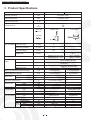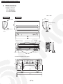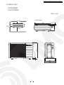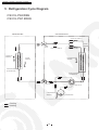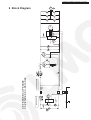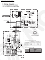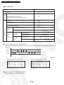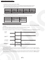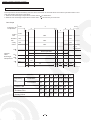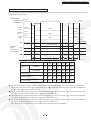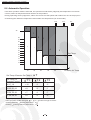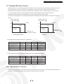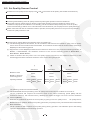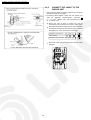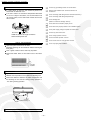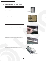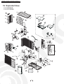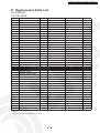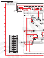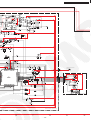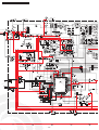
1
Order No. GMAC0506048C3
Air Conditioner
CS/CU-PE9DKE
CS/CU-PE12DKE
AUTO
HEAT
COOL
DRY
OFF
hr AY
DEL
ON
hr AY
DEL
ON
OFF
OFF
L
ANCE
SET/C
T
SELEC
ET
OR RES
ERR
RTER
INVE
WARNING
This service information is designed for experienced repair technicians only and is not designed for use by the general public.
It does not contain warnings or cautions to advise non-techical individuals of potential dangers in attempting to service a product.
Products powered by electricity should be serviced or repaired only by experienced professional technicians. Any attempt to service
or repair the product or products dealt with in this service information by anyone else could result in serious injury or death.
CONTENTS
Page
-------------------------------------------------------- 2
2 Functions ------------------------------------------------------ 3
3 Product Specifications ------------------------------------------ 6
4 Dimensions ----------------------------------------------------- 10
5 Refrigeration Cycle Diagram ----------------------------------- 12
6 Block Diagram -------------------------------------------------- 13
7 Wiring Diagram ------------------------------------------------- 14
8 Operation Details ----------------------------------------------- 15
9 Installation instructions --------------------------------------------------- 41
1 Features
R
Page
10 Installation and Serving Air Conditioner Using R410A
50
-------------------------------------- 62
12 Troubleshooting Guide ---------------------------------------- 65
13 Technical Data -------------------------------------------------- 67
14 Exploded View -------------------------------------------------- 68
15 Replacement Parts List ----------------------------------------- 69
16 Exploded View -------------------------------------------------- 70
17 Replacement Parts List ----------------------------------------- 71
18 Electronic Circuit Diagram -------------------------------------- 72
11 Disassembly of The Parts
C Guangzhou Matsushita Air Conditioner Co., Ltd.
(GMAC) All rights reserved. Unauthorized copying
and distribution is violation of law.
CS-PE9DKE / CU-PE9DKE / CS-PE12DKE / CU-PE12DKE
1 Features
High Efficiency
Enviromental Friendly (For Refrigerant : R410A Model)
Zero ozone depleting potential and low global
warming potential by using R410A refrigerant.
Air Quality Indicator
Comfort Environment
Air filter with function to reduce dust and smoke
Auto Restart Control
Removable and washable Front Panel
Automatically restart after power failure
12-hour Timer Setting
Breakdown Self Diagnosis function
Delay ON Timer and OFF Timer
2
CS-PE9DKE / CU-PE9DKE / CS-PE12DKE / CU-PE12DKE
2 Functions
Remote Control
AUTO
HEAT
COOL
DRY
OFF
hr
DELAY
OFF
ON
hr
DELAY
OFF
SELECT
ON
SET/CANCEL
ERROR RESET
INVERTER
AIR
SWING
OFF/ON
Operation START/STOP
MODE
Turn on/off the air conditionor
Horizontal Airflow Direction Control
When stop the operation by pressing
-Auto Control
OFF/ON button,the cursor key points
-Manual Control
to OFF.
Vertical Airflow Direction Manual Control
TEMP
Operation Mode Selection
Room Temperature Setting
Temperature Setting(16
Automatic Mode Operation
to 30
)
Auto Operation
Heating Mode Operation
TIMER
OFF/ON
Cooling Mode Operation
FAN
SPEED
Airflow Direction Control
Soft Dry Mode Operation
Timer Operation Selection
Indoor Fan Speed Selection
Stop/Start Operation Control
TIMER
SET/
CANCEL
Low Speed
Med- Speed
(set the ON/OFF Timer hourly later)
Set /Cancel Timer Operation
Set timer/Cancel the set timer
Med Speed
By pressing SET button for 5seconds
continuously to switch to set the sensor
Med+ Speed
sensitivity.
CHECK
Check Point
High Speed
Self diagnosis function
ERROE
RESET
Automatic Speed
ERROE Reset Point
A,B
To reset the indoor unit.
Time Changing Button
RESET
Reset Point
Change the setting time.
Clear memory data
3
CS-PE9DKE / CU-PE9DKE / CS-PE12DKE / CU-PE12DKE
Indoor Unit
Auto Switch
Button
Power Switch ON/OFF
Anti-freezing Control for the Evaporator
When the remote control cannot be used or
for repairing and testing ,please use this
button.
Cooling or Soft Dry Operation
Force Cooling Operation
Time Delay Safety Control
Keep pressing this button for 5 seconds to start
the force cooling operation.
The unit will restart operation in 3-4
minutes after each pause.
Force Heating Operation
Keep pressing this button for 8 seconds to start
the force heating operation.
Warm Booting Control
Different Remote Controlling Setting
Indoor fan starts running when indoor
Keep pressing this button for 11 to change
different remote controlling setting(A B)
Mode.
piping temperature reaches 19
or above.
Indoor Fan Speed Control
Signal Receiving Sound
High,Med+, Med, Med-,Low
Keep pressing this button for 16 seconds to turn
off or turn on the signal receiving sound or
H14 Abnormality Detection Mode.
Auto Fan Speed
Airflow Direction Control
Operation Indication Lamps
Power (green)
Timer(orange)
Automatic Airflow Direction Control
The louver automatically swings up and down
Lights up in operation;
Blinks during Hot Start
operation and
determining Auto
Operation mode
Light up in Timer Setting.
Five Manual Airflow Direction Control
Delayed On-timer Control
For cooling or soft dry mode, the unit
Blinks in Self Diagnosis Control
Air quality
Green
Orange
Red
starts 15 minutes before the set time with
the remote control, but for heating mode
30 minutes before the set time.
Automatic Restart Control
Operation Mode
Operation is restarted after power failure
at previous setting mode.
Cooling/Heating/Soft Dry /Auto Operation
4
CS-PE9DKE / CU-PE9DKE / CS-PE12DKE / CU-PE12DKE
Outdoor Unit
Pana sonic
4-way Valve Control
Total Running Current Control
If the unit is stopped during Heating
Operation, the 4-way valve will remain in
heating mode operation for 3 minutes.
Deice Operation
Overload Protector
Inner protector
30 Seconds Forced Operation Control
Once the compressor is activated, it does not
stop within 30 seconds. It stops immediately with
remote control ON/OFF button.
5
CS-PE9DKE / CU-PE9DKE / CS-PE12DKE / CU-PE12DKE
3 Product Specifications
Unit
CS-PE9DKE
CU-PE9DKE
Cooling Capacity
kW
2.50(0.90-3.00)
Heating Capacity
kW
3.30(0.90-4.00)
Moisture Removal
L /h
-
Power Source
Phase
V
Cycle
Single
230
50
Airflow Method
OUTLET
SIDE VIEW
TOP VIEW
INTAKE
Air Circulation Indoor Air (low)
m3/min
6
-
Indoor Air (medium)
m3/min
7.7
-
Indoor Air (high)
m3/min
9.8
-
Outdoor Air
m3/min
-
22.5
Electrical
Data
Cooling:high46
Cooling:high42,Low27
Heating:high47
Heating:high42,Low27
Cooling:730(190-1000)
Heating:820(170-1110)
Cooling:3.4
Heating:3.7
Cooling:2.95(2.58-4.05)
Heating:3.46(3.10-4.53)
3.7
G:half union3/8"
G:3-way valve3/8"
L:half union1/4"
L:2-way valve1/4"
G:gas side3/8"
G:gas side3/8"
L:liquid side1/4"
L:liquid side1/4"
12
0.65
1.9
3 core-wire/1.5mm2
280
540
799
780
183
289
8
30
Rotary(1
cylinder)
Rolling piston type
Induction(6 poles)
650
-
dB(A)
Noise Level
Input
W
Running Current
A
EER/COP
W/W
Starting Current
A
Inch
Inch
Inch
Inch
mm
m
Piping Connection Port(Flare piping)
Piping Size(Flare piping)
Inner Diameter
Length
Power Supply Cord Length
(Number of core-wire)
Drain Hose
Height
Width
Depth
Dimensions
Net Weight
Compressor
m
mm
mm
mm
kg
Type
Motor
Air Circulation
Type
Rated output
W
type
type
Input
Rated Output
Low
Fan
Med
Speed
High
Cross-flow fan
Motor
Induction(8poles)
30
840 60
1080 60
1370 60
W
W
rpm
rpm
rpm
6
Propeller fan
Induction(6 poles)
15
670 60
CS-PE9DKE / CU-PE9DKE / CS-PE12DKE / CU-PE12DKE
Unit
Heat
Exchanger
CS-PE9DKE
Evaporator
Copper
Slot type
Description
Tube Material
Fin Type
(Plate fin configuration,forced draft)
Rows/Stage
FPI
Dimensions
Refrigerant Control Device
Refrigeration Oil
Refrigerant (R410A)
Thermostat
Protection Device
Length
Capillary
Circulation
Inner Diameter
2 x 15
20
mm
610x252x25.4
(c.c)
-
g
mm
L/min
mm
Electronic Control
-
1X24
18.5
726x504x18.2
Capillary Tube
RB68A or Freol Alpha68M
840
sensor
Inner protector
600 10
8.15 0.2
1.3
P.P. Honeycomb
Air Filter
Refrigerant Circulation Control Device
Fan Motor Capacitor
CU-PE9DKE
Condenser
Copper
Corrugation type
Capillary
F,V
Specifications are subject to change without notice for further improvement.
7
1.2 F , 450V
CS-PE9DKE / CU-PE9DKE / CS-PE12DKE / CU-PE12DKE
Unit
CS-PE12DKE
CU-PE12DKE
Cooling Capacity
kW
3.15(0.90-3.80)
Heating Capacity
kW
4.10(0.90-5.00)
Moisture Removal
L /h
-
Power Source
Phase
V
Cycle
Single
230
50
Airflow Method
OUTLET
SIDE VIEW
TOP VIEW
INTAKE
Air Circulation Indoor Air (low)
m3/min
6.8
-
Indoor Air (medium)
m3/min
8.4
-
Indoor Air (high)
m3/min
9.9
-
Outdoor Air
m3/min
-
27.4
Electrical
Data
Cooling:high48
Cooling:high42,Low30
Heating:high50
Heating:high42,Low33
Cooling:900(190-1270)
Heating:1110(170-1410)
Cooling:4.2
Heating:4.9
Cooling:2.98(2.57-4.05)
Heating:3.18(3.07-4.53)
4.9
G:half union3/8"
G:3-way valve3/8"
L:half union1/4"
L:2-way valve1/4"
G:gas side3/8"
G:gas side3/8"
L:liquid side1/4"
L:liquid side1/4"
12
0.65
1.9
3 core-wire/1.5mm2
280
540
799
780
183
289
8
34
Rotary(1
cylinder)
Rolling piston type
Induction(6 poles)
650
-
dB(A)
Noise Level
Input
W
Running Current
A
EER/COP
W/W
Starting Current
A
Inch
Inch
Inch
Inch
mm
m
Piping Connection Port(Flare piping)
Piping Size(Flare piping)
Inner Diameter
Length
Power Supply Cord Length
(Number of core-wire)
Drain Hose
Height
Width
Depth
Dimensions
Net Weight
Compressor
m
mm
mm
mm
kg
Type
Motor
Air Circulation
Type
Rated output
W
type
type
Input
Rated Output
Low
Fan
Med
Speed
High
Cross-flow fan
Induction(8poles)
30
950 60
1170 60
1380 60
Motor
W
W
rpm
rpm
rpm
8
Propeller fan
Induction(6 poles)
25
770 60
CS-PE9DKE / CU-PE9DKE / CS-PE12DKE / CU-PE12DKE
Unit
Heat
Exchanger
CS-PE12DKE
Evaporator
Copper
Slot type
Description
Tube Material
Fin Type
(Plate fin configuration,forced draft)
2 x 15
2X24
20
17
Rows/Stage
FPI
Dimensions
mm
610x252x25.4
Refrigerant Control Device
Refrigeration Oil
(c.c)
-
Refrigerant (R410A)
Thermostat
Protection Device
Length
Capillary
Circulation
Inner Diameter
g
mm
L/min
mm
Electronic Control
-
726
696 X504x18.2
Capillary Tube
RB68A or Freol Alpha68M
1020
Inner protector
300 10 565 20
11.3 0.2 12.3 0.2
1.3
1.5
P.P. Honeycomb
Air Filter
Refrigerant Circulation Control Device
Fan Motor Capacitor
CU-PE12DKE
Condenser
Copper
Corrugation type
Capillary
F,V
Specifications are subject to change without notice for further improvement.
9
1.8 F , 450V
CS-PE9DKE / CU-PE9DKE / CS-PE12DKE / CU-PE12DKE
4 Dimensions
Indoor Unit
CS-PE9DKE
CS-PE12DKE
Unit : mm
Side view
Front View
183
Air intake
280
Right Piping
Hole
Air outlet
<Back View>
Gas Side
Installation Plate Hook
Liquid
Side
hr
DELAY
OFF
ON
hr
DELAY
OFF
ON
141
AUTO
HEAT
COOL
DRY
OFF
SELECT
SET/CANCEL
ERROR RESET
INVERTER
(100)
57
(50)
(420)
17.1
Drain Port
Installation plate (Front View)
254
A
B
95
Left Piping
Hole
(131)
(382)
(631)
10
(118)
CS-PE9DKE / CU-PE9DKE / CS-PE12DKE / CU-PE12DKE
Outdoor Unit
CU-PE9DKE
CU-PE12DKE
Unit : mm
105
780
570
48
57
18.6
<Top View>
10cm
or more
289
10cm
or more
100cm
or more
INVERTER
11
CS-PE9DKE / CU-PE9DKE / CS-PE12DKE / CU-PE12DKE
5 Refrigeration Cycle Diagram
CS/CU-PE9DKE
CS/CU-PE12DKE
INDOOR UNIT
OUTDOOR UNIT
CAPILLARY TUBE C1
LIQUID
SIDE
PIPING
SENSOR
2-WAY
VALVE
CAPILLARY TUBE C3
INTAKE AIR
SENSOR
CAPILLARY TUBE C2
OUTDOOR AIR
SENSOR
PIPING
SENSOR
HEAT EXCHANGER
(EVAPORATOR)
HEAT EXCHANGER
(CONDENSOR)
GAS SIDE
3-WAY VALVE
COMPRESSOR
SENSOR
Cooling
Heating
12
4-WAY VALVE
COMPRESSOR
FM
3
2
OUTDOOR UNIT
REACTANCE
4-WAY VALVE
FM
FM
6 Block Diagram
THERMAL
FUSE
INDOOR UNIT
CS-PE9DKE/CU-PE9DKE
CS-PE12DKE/CU-PE12DKE
CS-PE9DKE / CU-PE9DKE / CS-PE12DKE / CU-PE12DKE
CS-PE9DKE / CU-PE9DKE / CS-PE12DKE / CU-PE12DKE
7 Wiring Diagram
CS-PE9DKE/CU-PE9DKE
CS-PE12DKE/CU-PE12DKE
ELECTRONIC
CONTROLLER
(DISPLAY,RECEIVER)
W
W
R
W
CN-DISP
(W)
MOTOR
BR
W
CN-STM
(W)
CN-DISP
(Y)
W
W
O
Y
P
W
W
AUTO SW
W
WIRELESS REMOTE CONTROL
SENSOR
(PIPING TEMP.)
W
ELECTRONIC
CONTROLLER
(MAIN)
CN-TH
(Y)
FUSE
T 2.5A L 250V
POWER SUPPLY CORD
R
B
BR
MOTOR
BL
W
B
Y
BL
W
CN-FM
(W)
R
Y/G
INDOOR UNIT
3
TERMINAL
TERMINAL
YELLOW
3
BL
OUTDOOR UNIT
AC-WHT
(WHITE)
R
W
AC-BLK
(BLACK)
DATA
(RED)
BLUE
FUSE
G
RED
TRADE MARK
COMPRESSOR TERMINAL
G
SENSOR
(AIR TEMP)
SENSOR
(PIPING TEMP)
1
2 CN-TH
3 (WHITE)
4
SENSOR
(COMP. TEMP)
1 CN-TANK
3 (WHITE)
CT101
OUTDOOR FAN MOTOR RESISTANCE( )
+
COIL COMP
(4-WAY VAVLE)
CU-PE9DKE
CONNECTING
Y-B M
Y-R A
Y
GRY
Y
Fan Motor
CAPACITOR
B
T
+
Fm2
B
Y
CU-PE9DKE
CONNECTING
P
N
290
287
COMPRESSOR RESISTANCE( )
+
+ +
L6LAJAG00001
REACTOR
+
FUSE2
T3.14A L250V
Y
CU-PE12DKE
GRY
-
Fm1
L6LAHAG00001
COMPRESSOR
(RED)
R
U-V
(BLUE)
B
U-W
(YELLOW)
Y
V-W
Y/G
14
CU-PE12DKE
CS-PE9DKE / CU-PE9DKE / CS-PE12DKE / CU-PE12DKE
8
Operation Details
8.1 Operation and Display of Remote Controller
Original Setting
AUTO
FAN
SPEED
AIR
SWING
AUTO
HEAT
AUTO
COOL
DRY
OFF
hr
DELAY
hr
DELAY
OFF
ON
A
OFF
ON
B
ON/OFF Button
ON/OFF Switch
Signal Transmitting
Indoor Indicator
Green
Mode Selecting Button
1.Function and Display of the button:
AUTO, HEAT, COOL, DRY can be selected by pressing the button. Initial display of LCD is as follow
MODE
SET TEMP
FAN SPEED
AIR SWING
AUTO
25
AUTO
AUTO
HEAT
20
AUTO
AUTO
COOL
28
AUTO
AUTO
DRY
25
AUTO
AUTO
Keeping the button depressed continuously, the operation mode will change as
HEAT
COOL
DRY
AUTO
15
CS-PE9DKE / CU-PE9DKE / CS-PE12DKE / CU-PE12DKE
2.Shift time of the Mode selection button
Single press
Mode Selecting Button
LCD of Remote Control
HEAT
AUTO
Signal Transmitting
500ms
t
Keep depressed( less than 500ms)
Mode Selecting Button
LCD of Remote Control
AUTO
HEAT
COOL
DRY
Signal Transmitting
t
500ms
Keep depressed continuously
Mode Selecting Button
LCD of Remote Control
AUTO
HEAT COOL DRY AUTO
HEAT
Signal Transmitting
T1
T
T1=1s
T2 250ms
T
T
T2
T=250ms
t 500ms
If the ON/OFF button is pressed after the operation mode is set, or change the operation mode during operation,
or the signal is received from the remote controller, the indoor indicator will flash or light up to start the operation.
Fan Speed Button
1.The display on the remote controller changes as follow by pressing the AIR SWING button.
AUTO
2.If the ON/OFF button is pressed after the fan speed mode is set, or change the fan speed mode during operation,
or the signal is received from the remote controller, the indoor indicator will flash or light up to start the operation.
3.The shift time of the fan speed button is the same to that of mode selecting button.
16
CS-PE9DKE / CU-PE9DKE / CS-PE12DKE / CU-PE12DKE
Temp Adjusting Button
1.Press this button to change the set temperature
Increase the set temperature(Max.30
)
Decrease the set temperature(Min.16
)
2.If the ON/OFF button is pressed after temperature is set, or change the temperature during operation,
or the signal is received from the remote controller, the indoor indicator will flash or light up to start the operation.
Timer Set Button
1.The Function of the Timer-Setting Button
1) SELECT Button
When the airconditioner is in operation
OFF Timer Setting
OFF-ON Timer Setting
hr
DELAY
hr
DELAY
OFF
hr
DELAY
OFF
A
B
Exit Timer Setting
ON
A
B
When the airconditioner is turned off.
Make sure that the cursor key on the display of remote control points to OFF .
ON-OFF Timer Setting
ON Timer Setting
Eixt Timer Setting
FAN
SPEED
AIR
SWING
hr
DELAY
ON
hr
DELAY
OFF
ON
B
A
A
hr
DELAY
OFF
B
2) Timer Selecting Button A and B
The set time can be changed with manner of 1,2,3,4,5,6,7,8,9,10,11,12,1,2,3,4... By pressing the buttons.
Pressing the button A can change the time for ON Timer and OFF Timer, off time for OFF-ON Timer, on time for
ON-OFF Timer; Pressing the button B can change the time for on time for OFF-ON Timer and off time for
ON-OFF Timer setting.
3) SET/CANCEL Button
1 Pressing the button to set or cancel the set timer during the timer setting or activate the previous timer setting.
After the timer setting is determined, “ON” or “OFF” will stop flashing. If the timer setting is cancelled, “ON” or
“OFF” will disappear on the remote control display.
2
The time on the remote control will change every hour.
By pressing this button for 5 seconds continuously, the number indicating the air quality sensor sensitivity will
appear in the remote control display. Then press
Indicate
Sensitivity
0
Turn off the air quality
1
Normal
or
button to increase pr decrease the sensitivity.
2
3
Standard
hight
Notes:
OFF Timer and OFF- ON Timer can only be set during the operation;
During the operation, if the ON Timer or ON-OFF Timer is set, the operation will be stopped.
Timer setting can operate only once.
If the OFF/ON button on the remote control or the AUTO Switch on the indoor unit is pressed, the timer setting
will be cancelled.
If Auto Restart Control occurs , timer setting will be cancelled.
17
CS-PE9DKE / CU-PE9DKE / CS-PE12DKE / CU-PE12DKE
2.Timing Chart of Timer-Setting
1) OFF Timer
Initial Time
Changed Time
3 hours later OFF
OFF Timer Setting
2 hours
1
Timer Indicator
Remote Control LCD
2
3 hours
Operation Indicator
Indoor Unit
1:During timer operation changing the set time.
2:During timer operation press the ON/OFF button to cancel the OFF-Timer and the timer indicator on
the indoor unit will go off.
2) ON Timer
Initial Time
Changed Time
5 hours later ON
ON Timer Setting
Timer Indicator
5 hours
Remote Control LCD
Operation Indicator
Indoor Unit
OFF/ON Button
Preparation for operation
About Cursor Key Which Points To “OFF” On Remote Control
When the ON/OFF button on the remote control is pressed, the cursor key which points to “OFF” will appear or
disappear to indicate the ON/OFF status of the air conditioner.
FAN
SPEED
AIR
SWING
PRESS "OFF/ON" BUTTON
For some reason (Ex. The signal of the remote control does not reach the signal receiver of the indoor unit.), the
display of the remote control will not correspond with the actual ON/OFF status of the indoor unit:
1. The air conditioner is running but the cursor key which points to “OFF” appears. The air conditioner can be
stopped with any button (Except for “ON/OFF”, “TIMER SET”, “TIMER ON”) pressed.
2. The air conditioner is on standby, but the cursor key which points to “OFF” disappears. The air conditioner can
be started with any button(Except for “ON/OFF”, “TIMER SET”, “TIMER OFF”) pressed.
18
CS-PE9DKE / CU-PE9DKE / CS-PE12DKE / CU-PE12DKE
Air Swing Button
The airflow direction will change as below by pressing the AIR SWING button.
Airflow Direction:
AUTO
Display of Diagnosis
Refer to Diagnosis section.
Change the Code of Remote Controller
Change the code of remote controller by joining or cutting jump wire on the remote controller and indoor PCB.
Four codes(A,B,C,D) can be selected.
J----B
J
B
Short
Inside the battery box of
Indoor PCB
On indoor PCB
Open
Short
A
B
Open
C
D
remote controller.
8.2 Operation and Display of Indoor Unit
AUTO Operation Switch
SW ON
5s
Function
AUTO
Operation
Number of beep
8s
Forced
COOL
1
11s
Forced
HEAT
2
16s
Individual
Counter-action
Various Setting
Mode
3
21s
4
1. When the switch is pressed between 0 to 5 seconds, Auto Mode operation starts to function.
2. When the switch is pressed between 5 to 8 seconds, the unit is forced to operate in Cooling Mode.
3. When the switch is pressed between 8 to 11 seconds, the unit is forced to operate in Heating Mode.
4. When the switch is pressed between 11 to 16 seconds and together with the signal from the remote controller,
the unit can be changed to different controlling setting .
5. When the switch is pressed between 16 to 21 seconds, either H14 error detection selection mode or remote
controller’s signal receiving sound can be cancelled or turned on.
6. If the intake air temperature is less than 16
and the Forced Cooling is activated, because the prior operation
mode is heating, the compressor will stop for 3 minutes to start the Forced Cooling operation.
19
CS-PE9DKE / CU-PE9DKE / CS-PE12DKE / CU-PE12DKE
Indoor Unit Indicator
ON
Operation
OFF
Run
(Green)
Timer
Hot start, deice control,
mode judging and ONTimer Operation detecting.
Stop
Timer set
(Orange)
FLASH
Malfunction happens.
Timer not set
Air Quality
The air quality can be detected automatically by the air quality sensor and shown
(Green
Orange
Red )
by the color of the air quality indicator as bellow..
Color of indocator :Green
Air qualuty: Normal
Orange
Poor
Red
Bad
8.3 Common Features
Indoor Fan Motor Control
1. Basic Fan Speed
Fan speed is determined by the setting of the remote control. And W5~W6 can be calculated
according the equations below:
Those operation modes W4:Low , W8 : Hi , W10 have been regulated in the EEPROM data.
Me- : W5=W4+W10
Me : W6=W5+W10
Me+ : W7=W6+W10
Cool.Dry
REMOTE
CONTROL
FAN SPEED
SHI
HI
ROTATING
SPEED
W9C
W8C
Me
Me+
Me-
Calculated
Lo
Lo-
Slo
Sslo
W4C
W3C
W2C
W1C
Lo
Lo-
Slo
Sslo
W3W
W2W
W1W
Heat
REMOTE
CONTROL
FAN SPEED SHI
ROTATING
SPEED
HI
W8W
Me
Me+
Calculated
Me-
W4W
20
CS-PE9DKE / CU-PE9DKE / CS-PE12DKE / CU-PE12DKE
Basic fan speed of indoor unit
PE9DKE
PE12DKE
SHI
W 9C
1420
1430
HI
W 8C
1360
1370
M e+
W 7C
1190
1270
Me
W 6C
1070
1160
M e-
W 5C
950
1050
Lo
W 4C
830
940
Lo-
W 3C
770
880
S lo
W 2C
740
840
SSLo
W 1C
660
720
In te rv a l
W 10C
120
110
SHi
W 8W
1420
1440
M e+
W 7W
1270
1340
Me
W 6W
1150
1360
M e-
W 5W
1030
1180
Lo
W 4W
910
1100
Lo-
W 3W
670
800
S lo
W 2W
580
580
SSLo
W 1W
400
400
In te rv a l
W 10C
120
80
COOL
HEAT
2. Indoor Fan Control
Cool/Dry Operation
Cool Operation
Protection Operation
Me
Forced Cool
Hi
Other than above
Minimum Control
Other than above
Dry Operation
Mode judging for Auto
Operation ON-Timer
Operation detecting
Mode judging during
ON-Timer detecting
Other
than
above
Auto Fan
LoLo
Manual Fan
Setting of Remote
Auto Fan
Other than
above
Normal Auto Fan
Manual Fan
Other than
above
Fan Speed Set
21
Slo
Slo
CS-PE9DKE / CU-PE9DKE / CS-PE12DKE / CU-PE12DKE
Heat Operation
Protection Operation
Me
Forced Heat
Shi
Other than above
Minimum
Control
Mode judging in Auto Operation
Preparing Operation of Timer-ON operation
Lo-
Hot Start
Stop
Deice Control
Stop
Low Temperature Control
SSHi
Maximum
Control
Relay OFF(Comp OFF)
Indoor Piping Temp Control(Auto Fan)
Detection of
Timer-ON
Operation
Other
than
above
SLo- or SSLo
Refer to the following contents
Auto Fan Speed
Lo
Manual Fan Speed
Setting On Remote Control
Auto Fan Speed
Other than
above
Auto
Manual Fan Speed
Setting On Remote Control
Auto Fan Speed for Cooling Operation
Following eight patterns repeat over and over for auto fan speed. Each pattern persists ten
second.
No.C
No.B
No.A
a
b
c
d
e
f
g
h
a
b
UNIT: rpm
Temp. Of outdoor unit under 35
PE9DKE
PE12DKE
No.A
970
1070
No.B
990
No.C
950
Temp. Of outdoor unit above 35
PE9DKE
PE12DKE
No.A
1130
1220
1090
No.B
1150
1240
1050
No.C
1110
1200
Auto Fan Speed for Heating Operation
Refer to Piping Temperature Control.
22
CS-PE9DKE / CU-PE9DKE / CS-PE12DKE / CU-PE12DKE
3. Deodorizing Control
This type of control is applicable on Cooling Mode and Soft Dry Mode operating only.
During cooling or soft dry operation with automatic fan speed, the unit will operate as state below for deodorizing purpose.
Deodorising Status
1
2
3
4
5
ON
Compressor status
5
4
1
4.5.4....
OFF
Period(sec)
40
50
…
Indoor fan speed
OFF
Slo
Note*
ON
20
90
20
90
Slo
OFF
Slo
OFF
40
OFF
ON
ON
COMP
OFF
FM
OFF
Note*:Fan speed is automatic for cooling mode and Slo for soft dry mode.
Outdoor Fan Motor Control
1. Specification of outdoor fan motor
Model
Fan Motor
Speed(rpm)
CU-PE9DKE
Induction Motor(6 Poles 1 speed)
670
CU-PE12DKE
Induction Motor(6 Poles 1 speed)
770
2. Operation of the fan motor
The outdoor fan runs during the operation of the compressor or within 30 seconds after the compressor stops.
ON
ON
Compressor
Outdoor Fan
OFF
ON
ON
OFF
30 seconds
23
CS-PE9DKE / CU-PE9DKE / CS-PE12DKE / CU-PE12DKE
Frequency for Compressor Operation
1. Basic Frequency
If the frequency for the compressor calculated is prohibited, 1 Hz larger than this calculated
one will be selected.
Cool Dry
12
13
14
15
16
17
18
19
20
21
22
23
24
25
26
27
28
29
30
31
32
33
34
35
36
37
38
39
40
41
42
43
44
45
12
12
9
12
12
9
12
12
46
47
48
49
50
51
52
53
54
55
56
57
58
59
60
61
62
63
64
65
66
67
68
69
70
71
72
73
74
75
76
77
78
79
Heat
12
13
14
15
16
17
18
19
20
21
22
23
24
25
26
27
28
29
30
31
32
33
34
35
36
37
38
39
40
41
42
43
44
45
80
81
82
83
84
85
86
87
88
89
90
91
92
93
94
95
96
97
98
99
100
101
102
103
104
105
106
107
108
109
110
111
112
113
12
9
9
9
9
46
47
48
49
50
51
52
53
54
55
56
57
58
59
60
61
62
63
64
65
66
67
68
69
70
71
72
73
74
75
76
77
78
79
80
81
82
83
84
85
86
87
88
89
90
91
92
93
94
95
96
97
98
99
100
101
102
103
104
105
106
107
108
109
110
111
112
113
12
12
12
12
9
9
9
12
12
12
12
2. Starting Control
Within 300 seconds after the start-up of the compressor, the frequency for the compressor
will change as below.
Start-up after the micron reset
Start-up after thermal off ( Set Temp Reached, heating mode)
Time From Start-up of
Compressor
60
60-120s
120-300
Min.Hz
Max.Hz
40
40
\
40
40
110
Start-up after thermal off ( Set Temp Reached)
Time From Start-up of
Compressor
60
60-120s
120-300
Min.Hz
Max.Hz
38
38
\
38
38
119
Time From Start-up of
Compressor
60
60-120s
120-300
Min.Hz
Max.Hz
40
40
\
40
40
119
Start-up under other conditions
Time From Start-up of
Compressor
60
60-120s
120-300
24
Min.Hz
Max.Hz
40
40
\
40
40
110
CS-PE9DKE / CU-PE9DKE / CS-PE12DKE / CU-PE12DKE
Protection Control
A. Time Delay Safety Control
1.The compressor will not start for 3 minutes after the stop of the operation.
2.This control is not applicable if the power supply is turned off and turned on again.
B. 30 Seconds Forced Operation
1.Once the compressor starts operation, it will not stop for 30 seconds.
2.However, it can be stopped using remote controller or Auto Switch on indoor unit.
C. Total Running Current Control
1.When the total outdoor unit running current(AC) exceeds I1 value, the frequency for
compressor will decline.
2. If the running current is less than I1 value for 10 seconds, the frequency for compressor
will increase.
3.However, if the total outdoor running current exceeds 17.0A, compressor will be stopped
immediately for 3 minutes.
Current Value (A)(I1)
Outdoor Piping Temp
COOL
A
B
HEAT
PE9DKE
4.5
4.4
PE1DKE
6.1
6.0
4.0
4.0
5.0
5.0
B
38.5
37.5
A
D. IPM Protection Control
1.DC Peak Current Control
1>When electric current to IPM exceeds set value of DC17.3 1A,the compressor will stop. It will
restart after three minutes.
2>If the set value is exceeded again within 30 seconds, the operation will restart after one minute.
If this condition repeats continuously for seven times, all indoor and outdoor relays will be cut off.
3>Error code [F99] will be displayed.
2.Overheating Protection Control
When the IPM temperature rises to 90.0 , compressor will stop immediately.
Compressor restarts after three minutes if the temperature decreases to 85 .
E. Compressor Overheating Prevention Control
The frequency is also controlled by the temperature of the compressor.
Protection Control
Comp OFF
112
8Hz/45Sec down.
108
97
Min.17Hz
96
105
113Hz
95
Free
25
CS-PE9DKE / CU-PE9DKE / CS-PE12DKE / CU-PE12DKE
F. Compressor Protection Control (Gas Leakage)
1.When the conditions listed in the table occur, the compressor stops and restarts after three minutes.
2. If this continuously occur for twice within 20 minutes, all indoor and outdoor relays will be cut off.
3.This control is not applicable for deice operation.
Comp Frequency
Total Outdoor Current
Indoor Piping Temp
Operation Mode
Model
45Hz or Above
64Hz or Above
Ib I 1.6
Ib I 1.3
25 or Less
20 or Above
Cool/Dry
Heat
PE9DKE
58Hz or Above
73Hz or Above
Ib I 1.3
Ib I 1.6
20 or Above
25 or Less
Cool/Dry
Heat
PE12DKE
G. Low Operation Frequency Protection Control
If one of the following conditions exists, the compressor will run with the frequency of 40 Hz
Intake Air Temp
30
or
15
_______
Outdoor Temp
38
or
16
24
Indoor Piping Temp
30
Operation Mode
or
4
0
Cool/Dry
Heat
4-way Valve Control
1. The 4-way valve will be turned on as the compressor starts to operate and remains on all the time during the heating
operation.
2.The 4-way valve remains on for less than 3 minutes after heating operation is stopped.
3.The 4-way valve remains off during cooling and soft dry operation.
4.If the operation is shifted from cooling or dry to heating mode, the switching of 4-way valve will be delayed for 3 minutes.
Heating
Comp
4-way Valve
Status
4-way Valve
Drive Signal
14V
Voltage Across
4-way Valve
5V
0V
2s
5.Heating Operation Mode
Four minutes after the start of the operation, if the indoor piping temperature detected is lower than 0
, the operation
will stop.( Restarts in 3 minutes) If this situation happens 4 times within 30 minutes, error code “F11” will be displayed.
6.Cooling Operation Mode
Four minutes after the start of the operation, if the indoor piping temperature detected is higher than 45
, the operation
will stop ( Restarts in 3minutes). If this situation happens 4 times within 30 minutes, error code “F11” will be displayed.
26
CS-PE9DKE / CU-PE9DKE / CS-PE12DKE / CU-PE12DKE
Airflow Direction Control
A. Vertical Airflow Direction
Vane Angle
Manual Airflow
Cool
7°
Auto Airflow
7°
14°
Auto Airflow
Auto Airflow
Direction
28°
35°
21°
28°
35°
45°
60°
7°
Manual Airflow
Heat
21°
7°~35°
Manual Airflow
Dry
14°
0°
15°
30°
C
14°
B
52°
A
7°
Notes:
Manual Airflow Direction: The vertical airflow vane will be fixed at the angle desired according to the instructions of remote
controller no matter the operation is cooling, soft dry or heating mode.
Auto Airflow Direction:
Cool : The vertical airflow vane will swing up and down within the range indicated in the
Form above.
Dry : Remain in the horizontal direction.
Heat :
The vertical airflow vane will change according to indoor piping temperature as below..
Vertical Airflow Vane
Indoor Piping
Temperature
127
C
127
33
B
30
A
Intake air
Temperature
Free
A
27
CS-PE9DKE / CU-PE9DKE / CS-PE12DKE / CU-PE12DKE
C. Mode Judgement for Auto Operation
Airflow Mode Setting
Manual
Auto
Initializing When Power-On
Lower Limit
Upper Limit
Position Previously Set
Upper Limit
Auto Operation
Shifted to Auto Mode
Same to Cool/Dry/Heat
Same to Cool/Dry/Heat
Note:
When the air-conditioner is turned on, if manual airflow direction is selected and the angle is lower than the lower limit
for heating operation, the airflow direction will be changed to the lower limit for heating mode. If Cooling operation is
determined during the mode judgement, the airflow direction will be shifted to lower limit for cooling operation.
D. About Timer-Setting
During On-Timer operation, the airflow direction can be changed between Manual and Auto.
Self Diagnosis
A. About Self Diagnosis
When the air-conditioner is stopped due to malfunction detected by itself, the operation can be restarted using AUTO
Switch on the indoor unit. In forced operation, the frequency for compressor and fan speed can not be changed and the
signal receiving sound is different.
Normal Operation ON: “pep”
Forced Operation ON: “pep”,“pep”,“pep”,“pep”
Stop:“pep”
Note: Refer to the Diagnosis Code Table for the malfunction when forced operation is not available.
B. Display of Error Code
1.Keeping the CHECK button on the remote controller depressed for 5 seconds, error code ranging from H11 to H99
can be displayed on the remote controller.
2.The error code is changed and diagnosis signal is transmitted to the indoor unit by pressing the Temp Up button on
the remote control.
3.When the malfunction of the air-conditioner matches the error code on the remote control, four beeps can be heard
from the indoor unit and the operation indicator will light up.
4.Keep the CHECK button depressed continuously for 5 seconds to cancel the diagnosis function.
Indoor Unit
Indoor Unit
TIMER
POWER
TIMER
“Pep”
POWER
“Pep, pep, pep, pep”
The error code doesn’t match the
malfunction of indoor unit.
The error code matches the
malfunction of indoor unit.
Remote controller
28
CS-PE9DKE / CU-PE9DKE / CS-PE12DKE / CU-PE12DKE
C. Diagnosis Code Table
Code
Abnormality/Protection
Judgment
Check
Emergency
Operation
H00
Normal
H11
Indoor/Outdoor abnormal
communication
>1minute after starting
operation
Connecting cable, Indoor
/outdoor PCB
H14
Indoor intake air temp sensor
abnormality
-
Intake air temperature sensor(
defected or disconnected)
X
H15
Outdoor compressor temperature
sensor abnormality
Continue for 5 sec.
Compressor temperature
sensor(defected or disconnected)
X
H16
Outdoor Current Transformer open
circuit
-
Outdoor PCB, IPM module
H19
Indoor fan motor mechanism lock
-
Indoor PCB, fan motor
Continue for 5 sec
Heat exchanger temperature
sensor
H23
Indoor heat exchanger temperature A
sensor abnormality
X
(defected or disconnected)
H25
Air filter abnormality
-
Outdoor air temperature sensor
abnormality
Continue for 5 sec
H27
H28
Outdoor heat exchanger temperature Continue for 5 sec.
sensor abnormality
Discharge temperature sensor
abnormality
Continue for 5 sec.
H30
Discharge temperature sensor
(defected or disconnected)
Incorrect connection of
Indoor/Outdoor cable
-
Indoor/outdoor supply voltage
H33
H97
Outdoor fan motor lock
Twice within 30 minutes Outdoor fan motor
Outdoor temperature sensor(
defected or disconnected)
Outdoor heat exchanger sensor
(defected or disconnected)
X
Air filter dirty
-
H98
Indoor high pressure protection
Indoor heat exchanger anti-freezing
protection
Indoor heat exchanger
freezing
Insufficient refrigerant
H99
Cooling/heating cycle changeover
abnormality
4 times occurrence
within 30 minutes
4-way valve
F11
F16
Cooling/Dry cycle changeover
abnormality
4 times occurrence
within 30 minutes
Indoor PCB
F90
PFC control
4 times occurrence
within 20 minutes
Voltage at PFC
Refrigeration cycle abnormality
2 times occurrence
within 20 minutes
No refrigerant
F91
Compressor abnormality
4 times occurrence
within 20 minutes
Compressor
F93
F95
Cool high pressure protection
4 times occurrence
within 20 minutes
Outdoor refrigeration cycle
-
Excessive refrigerant
F96
X
Air circulation short circuit
IPM overheating protection
Air filter dirty
V-coil
(3-way valve is closed)
-
X
X
X
X
X
Improper heat radiation
X
X
IPM
Insufficient refrigerant
F97
Outdoor compressor overheating
protection
4 times occurrence
within 20 minutes
Total running current protection
3 times occurrence
within 20 minutes
Excess refrigerant
F98
F99
4 times occurrence
continuously within 30
minutes
Outdoor PCB
Outdoor Peak Current Protection
Control
Compressor
Improper radiation
IPM
Compressor
29
X
X
X
X
CS-PE9DKE / CU-PE9DKE / CS-PE12DKE / CU-PE12DKE
8.3 Cooling Operation
Anti-freezing Control
1 .Frequency of the compressor
For prevention of freezing of the indoor evaporator, the frequency of the compressor will be changed according to
the indoor piping temperature.
13
Normal Control
7
Up Zone
6
Fixed
5
Down Zone
0
Comp Off
2 .Indoor Fan Control
Indoor fan speed changes according to the indoor fan speed.
10
Free
Cool:9
Dry:5
Cool:6
Dry:2
Up Zone
Outdoor Air Temp Control
Operation Frequency for Compressor
Outdoor
Air Temp
38
Outdoor
Air Temp
>40Hz
38
>40Hz
37
25
37
13-51Hz
25
10-64Hz
22
18
22
13-51Hz
18
10-64Hz
15
11
15
13-51Hz
11
10-64Hz
8
8
13-51Hz
12-64Hz
PE9DKE
PE12DKE
30
CS-PE9DKE / CU-PE9DKE / CS-PE12DKE / CU-PE12DKE
Anti-Fog Protection
1
The indoor fan speed is higher than A but less than B.
2
The indoor fan speed is less than A
Outdoor Air Temp
Operation Time(S)
>30
1
<30
>30
2
PE9DKE
PE12DKE
0-30
a
45
58
30-90
b
40
54
90-420
c
40
54
0-30
a
45
58
30-90
b
40
54
90-420
c
35
46
0-30
a
35
46
30-90
b
35
46
90-420
c
35
46
0-30
a
35
46
30-90
b
35
46
90-420
c
35
46
Indoor Fan Speed A
800
850
Indoor Fan Speed B
960
1020
<30
Overload Protection For Cooling Operation
The frequency for the compressor will change according
to the outdoor piping temperature.
*1 PE9DKE
*2 PE12DKE
Off
61
58
>40Hz
8Hz/45s Down
56
Fixed
55
55
40-51Hz(*1)
40-64Hz(*2)
53
31
CS-PE9DKE / CU-PE9DKE / CS-PE12DKE / CU-PE12DKE
8.4 Soft Dry Operation
Method of frequency shifting is the same to that of cooling operation and the intake air temperature is measured
every second.
Initial Frequency for Compressor
PE9DKE
PE12DKE
T<4
24
31
T
27
34
4
T=Outdoor Air Temp-Remote Control Setting Temp
Thermostat Features
2.5
Indoor Air TempSet Temp
0.5
Temperature
Shifting
-2.5
Thermo-Off
Indoor Fan Control
Cool
1.5
Indoor Air TempSet Temp
0.5
Dry
Slo
Temperature
Shifting
-2.5
Thermo-Off
8.5 Heating Operation
Indoor Fan Control
1.Indoor fan is controlled by the indoor piping temperature.
Manual Fan Speed
Min Me
K11
K10
K9
K8
K7
Set Speed on
Remote Control
Max. Lo
Piping Temperature( )
K6
Max.
Me
K5
K4
Lo-
K3
Slo
K1
Stop
K2
K0
K0
K1 K2 K3
16
19
32
K4
K5 K6 K7 K8 K9 K10 K10
24 322 342 35 36
39
42 55 55
58
CS-PE9DKE / CU-PE9DKE / CS-PE12DKE / CU-PE12DKE
Auto Fan Speed
K11
K9
K8
K7
K11
K10
Max.
Up
Fixed
Max. Lo
K5
Fixed
Down
K3
Lo-
K1
Slo
K9
K8
K7
K6
Max.Lo
Fixed
Down
K4
K5
K2
K3
Lo-
K1
Slo
K0
Stop
K10
Max.
Up
Up
K6
K4
Stop
K2
K0
2.During heating operation, the maximum fan speed is Lo when the compressor stops.
3.Hot Start
When the heating operation starts, the indoor fan stops and the compressor runs with the frequency of 117Hz.
This is to prevent the cold airflow from blowing.
If the piping temperature rises to 19
, and the indoor fan speed and airflow direction varies with the indoor piping
temperature, the hot start control is completed.
Overload Protection Control
The frequency for the compressor is determined by indoor piping temperature.
Stop
60
5Hz/30s Down
Max.47 Hz
Min. 40 Hz
55
53
Fixed
Max.62 Hz
48
Min. 40 Hz
52
46
Max.110Hz
48
Min. 40 Hz
44
Outdoor Air Temp Control
One minute after the start-up of the compressor, outdoor air temperature control starts.
Max. 64Hz
23
Min. 40Hz
21
16
Max. 110Hz
Min. 40Hz
14
Free
33
CS-PE9DKE / CU-PE9DKE / CS-PE12DKE / CU-PE12DKE
New JIS Deice Operation
Deice operation starts immediately after the deice instruction is received. But the first deice operation starts 1 hour
after the heating operation is activated.
1.Outdoor heat exchanger temperature is lower than3
for 30minutes.
2.Outdoor heat exchanger temperature is lower than -1 continuously for 3 minutes.
Time Graph
Frequency for
Compressor
Free
3
Free
2
1
Indoor
Unit
Outdoor
Fan
4-way
Valve
6
4
7
5
Free
Free
OFF
ON
ON
OFF
ON
ON
OFF
Deice
Terminated
17
Deice Operation
Outdoor
13
Heat
Exchanger
10
Temperature.
T2
-1
T3
T1
1
Frequency
For
Compressor
2
3
T4
T5
4
5
T6
T7
6
7
PE9DKE
58Hz
58Hz 71Hz
51Hz
51Hz
99Hz 99Hz
PE12DKE
58Hz
58Hz 71Hz
51Hz
51Hz
99Hz 99Hz
Indoor Fan
ON
OFF
OFF
OFF
OFF
ON
ON
Outdoor Fan
ON
OFF
OFF
OFF
OFF
ON
ON
4-way Valve
ON
OFF
OFF
OFF
OFF
ON
ON
34
CS-PE9DKE / CU-PE9DKE / CS-PE12DKE / CU-PE12DKE
Normal Deice Operation
Deice operation will start as the deice operation instruction is launched. But the first deice operation starts one hour after
the heating operation starts.
Time Graph
Frequency for
Compressor
Free
3
Free
2
6
4
1
Indoor
Unit
Outdoor
Fan
4-way
Valve
7
5
Free
Free
OFF
ON
ON
OFF
ON
ON
OFF
Deice
Terminated
18
Deice Operation
Outdoor
15
Heat
Exchanger
9
Temperature.
T2
-2
T3
T1
T4
1
Frequency
For
Compressor
2
3
4
T5
5
T6
6
T7
7
PE9DKE
40Hz
40Hz 65Hz
65Hz
40Hz
0Hz
0Hz
PE12DKE
40Hz
40Hz 65Hz
65Hz
40Hz
0Hz
0Hz
Indoor Fan
ON
OFF
OFF
OFF
OFF
OFF
ON
Outdoor Fan
ON
OFF
OFF
OFF
OFF
ON
ON
4-way Valve
ON
OFF
OFF
OFF
OFF
OFF
ON
If one of the following situations exists, the instruction of the deice will be launched: The outdoor heat exchanger
temperature remains less than 3
is higher than -1
for 120 minutes and -6
for 3 minutes continuously, the outdoor air temperature
and the compressor is on.
The outdoor heat exchanger temperature remains less than 3
the outdoor air temperature is higher than -1
The outdoor heat exchanger temperature remains less than 3
the outdoor air temperature is higher than -3
for 3 minutes continuously,
for 40 minutes and -9
for 3 minutes continuously,
and the compressor is on
The outdoor heat exchanger temperature remains less than 3
the outdoor air temperature is lower than -3
for 80 minutes and -7
and the compressor is on
for 40minutes and -11
and the compressor is on
Note: The first deice operation occurs 60 minutes after the beginning of the operation.
35
for 3 minutes continuously,
CS-PE9DKE / CU-PE9DKE / CS-PE12DKE / CU-PE12DKE
8.6 Automatic Operation
If the Auto operation mode is selected, the operation mode will be judged by set temperature on remote
control, intake air temperature and outdoor air temperature.
During operating mode judgement, indoor fan runs at low fan speed and outdoor fan runs in the purpose
of detecting the intake air temperature and outdoor air temperature (for 20 seconds)
HEAT
COOL
DRY
0
36
1
28
2
T1
3
27
26
25
24
0
1
23
4
22
5
T2
21
Set Temp
2
20
T3
19
3
18
17
16
13
19
Set Temp=Remote Set Temp +
Set Temp on
Remote Control
21
23
T
T1
T2
T3
16,17,18
+10
-3
-5
19,20,21,22
+8
-3
-7
23,24,25,26
+7
-3
-7
27,28,29,30
+6
-3
-8
If the operation mode changed,
Cooling /Soft Dry
Heating
T1,
25
T2,
T3 will change as follow:
Heating Operation: -2
Cooling /Soft Dry Operation: +2
36
Outdoor Air Temp
CS-PE9DKE / CU-PE9DKE / CS-PE12DKE / CU-PE12DKE
8.7 Delayed ON-Timer Control
Delay ON Timer ca be set using remote controller, the unit with timer set will start operate earlier than
the setting time. This is to provide a comfortable environment when reaching the set On time.
Seventy minutes before the set time for ON Timer or ON-OFF Timer setting, indoor ( at fan speed of
Lo-) and outdoor fan motor start operate for 20 seconds to determine the indoor intake air
temperature and outdoor air temperature in order to judge the operation mode.
From the above judgment, the decided operation will start operate earlier than the set time as shown
below.
Indoor intake air
temperature ( )
Indoor intake air
temperature ( )
40 Min
15 Min
30
15
10 Min
45 Min
25
5
5 Min
50 Min
30
25
Outdoor air
temperature ( )
Cooling/Soft Dry
Outdoor air
temperature ( )
0
5
Heating
Timer Signal Receiving Sound During Operation
Operation
ON Timer Set
OFF
OFF Timer Set
ON
ON-OFF Timer Set
OFF
OFF-ON Timer Set
ON
Sound
BeepBeep
BeepBeep
Timer LED Timer Setting
ON
Valid
ON
Valid
ON
Valid
ON
Valid
Timer Signal Receiving Sound When the Air Conditioner Stops
Operation
ON Timer Set
OFF
OFF Timer Set
OFF
ON-OFF Timer Set
OFF
OFF-ON Timer Set
OFF
8.8
Sound
Beep
None
Beep
None
Timer LED Timer Setting
ON
Valid
OFF
Invalid
ON
Valid
OFF
Invalid
Auto Restart Control
If there is a power failure, operation will be automatically restarted after 3-4 minutes when the power is
resumed. It will start with previous operation mode and airflow direction.
37
CS-PE9DKE / CU-PE9DKE / CS-PE12DKE / CU-PE12DKE
8.9 Air Quality Sensor Control
Resistance of air quality sensor: Rs(air)=10k ~50k ( The worse the air quality, the smaller the resistance.)
Basic Operation
Detecting and indicating of the air quality will not stop during the operation of the air conditioner.
The power of the air quality sensor is always on during the operation of the air conditioner. When the air
conditioner stops (The air conditioner is on standby.), the air conditioner will provide power to the air quality
sensor intermittently (It will be on for 3 minutes after each 109 minutes.) for the purpose of air quality detecting.
Within 2 minutes after the air conditioner starts to operate, the air quality sensor is in the process of preheating
and the air quality indicator is red.
Resistance Reference
Detecting of air quality( During the operation of the air conditioner)
(a) The measuring period is 20 minutes; The air conditioner will measure the resistance (Rs) of the air quality
sensor once each 2 seconds and record the data. The maximum Rs within the 20 minutes will be selected as
Rs(MAX) for this measuring period.
(b) Suppose the current Rs(MAX) as MAX and the resistance reference of the previous measuring period is as
MAXR1.; If MAX>MAXR1, the resistance reference of the current measuring period is MAXR=MAX; If
MAX<MAXR1, MAXR=MAXR1;
(c) Within 2 minutes after the power of the air quality sensor is turned on, the resistance reference of this
measuring period is the maximum resistance of the sensor during this period.
20minutes
20minutes
20minutes
Maximum of Rs
MAX1
MAX2
MAX3
MAXR1 of previous
measuring period
MAX0
MAX1
MAX2
Updating of MAXR
MAX1
MAX0
MAX0
MAX2
MAX1
MAX1
MAX3
MAX2
MAX2
MAX1
MAX0
MAX1
MAX2
MAX1
MAX2
MAX3
MAX2
MAX3
The following conditions should be fulfilled
(d) The initial MAXR after the preheating of the air quality sensor when the air conditioner is turned on:
The air conditioner will compare the maximum value of the current measuring period (MAX) with the
resistance reference 109 minutes before ( MAXR0) and select the bigger one as the current resistance
(e) reference(MAXR).
When the air conditioner determines the air quality is getting worse: Air quality level 1
Air quality level 2,
MAXR will not be updated; When the air quality gets better (air quality level 0), Rs detected at this time will be
(f)
MAX and MAXR.
The air conditioner will not detect the air quality during deicing operation. The indication prior to the deicing
operation will be held during the deicing operation.
38
CS-PE9DKE / CU-PE9DKE / CS-PE12DKE / CU-PE12DKE
Detecting of air quality( When the air conditioner is on standby.)
(a) After the air conditioner stops operation, it will provides power to the air quality sensor intermittently to detect
the air quality and update the resistance reference (MAXR). The power of the air quality sensor will be on for 3
minutes after each 109 minutes.
(b) During these 3 minutes, the air quality sensor will be in preheating process for 2 minutes and the other time is
for measuring the resistance. The air conditioner will compare the maximum resistance measured in this period
with the maximum value in the previous 109 minutes and the bigger one will be selected as resistance
Air Quality Control
Detecting of air quality(When the air conditioner is on standby.)
Rs/MAXR will be calculated automatically every 2 seconds and the air quality level will be determined in
accordance with the value below,
Air Quality Level
Signal of Air Quality Sensor
Air Quality
Getting Worse
Air Quality
Getting Better
Rs/MAXR
G1
(0)
(1)
Rs/MAXR
G2
(1)
(2)
Rs/MAXR
G3
(2)
(1)
Rs/MAXR
G4
(1)
(0)
Air quality
becomes better
Air
quality
(0) becomes worse
*G1=0.85
(1)
*G2=0.60
(2)
Set the sensitivity number of the air quality sensor as 2 (Standard)
Air Quality Level and Indicator
During preheating of the air quality sensor the air quality indicator is red.
The color of the air quality indicator varies with the air quality level:
Air Pollution Level 0: Green
Air Pollution Level 1:Orange
Air Pollution Level 2:Red
39
CS-PE9DKE / CU-PE9DKE / CS-PE12DKE / CU-PE12DKE
Forced Resetting
Forced Resetting Time (The added operation time mentioned later not included.)
(a) Air Pollution Level 2: Red: 5 minutes
Orange: 8 minutes
(B) Air Pollution Level 1: Red: 5 minutes
Orange: 8 minutes
Green
Green
Timer Resetting
When the forced resetting mode is determined and the following conditions are fulfilled, the timer is reset.
1) The air quality changes which results in the changing of the color of the air quality indicator.
2) Compare Rs detected in current 2 seconds with R1 detected in previous 2 seconds and Rs/R1<0.95.
3) Suppose Rs detected in previous 3 minutes is R2 and Rs/R2
0.87.
Added Operation of Air Quality Sensor
When the air quality getting worse
If the air pollution level changes from 0 to 2, the color of the air quality indicator changes as below,
Green
Orange (2 Sec.)
Red
When the air quality getting better (added operation )
If the air pollution level changes from 2 to o, the color of the air quality indicator changes as below,
Red (60 Sec. )
Orange( 60Sec.)
Green
Judgment during added operation
During added operation, if the air quality sensor judges that the air quality is getting worse, the added operation will
be stopped immediately and the air quality indicator will shift to normal indication. If the air quality getting better,
the air conditioner will judge the air quality until the added operation is finished.
Sensitivity Control of Air Quality Sensor
The sensitivity number can be changed through the following procedure
<Setting Sensitivity Number>
1.Keep the SET button on the remote control depressed continuously for 5 seconds to select sensitivity control
m ode.
2.The previous sensitivity setting will be displayed in the temperature display.
“0”=Turn off the air quality indicator
“1”= Low Sensitivity …………....G1=0.70, G2=0.45, G3=0.48, G4=0.73
“2”=Standard Sensitivity ………G1=0.85, G2=0.60, G3=0.63, G4=0.88
“3”=High Sensitivity................ G1=0.90, G2=0.65, G3=0.68, G4=0.93
3.Press or button on the remote control to change the sensitivity
Within 10 seconds after the sensitivity setting is finished, other settings are not available. The display of the remote
control will change back to normal without pressing any button.
40
CS-PE9DKE / CU-PE 9DKE / CS-PE12DKE / CU-PE12 DKE
9 Installation Instructions
1. Philips screw driver
2. Level gauge
Required tools for Installation Works
5. Spanner
9. Gas leak detector
6. Pipe cutter
10. Measuring tape
3. Electric drill, hole core drill 7. Reamer
(ø70 mm)
4. Hexagonal wrench (4 mm) 8. Knife
9.1.
11. Thermometer
13. Multimeter
14. Torque wrench
18 N.m (1.8 kgf.m)
42 N.m (4.2 kgf.m)
kgf.m)
15. Vacuum pump
12. Megameter
16. Gauge manifold
Safety Precautions
ı ıˇ ıˇıRead the following “SAFETY PRECAUTIONS” carefully before installation.
ı ıˇ ıˇıElectrical work must be installed by a licensed electrician. Be sure to use the correct rating of the power plug and main circuit
for the model to be installed.
ı ıˇ ıˇıThe caution items stated here must be followed because these important contents are related to safety. The meaning of each
indication used is as below. Incorrect installation due to ignoring of the instruction will cause harm or damage, and the
seriousness is classified by the following indications.
This indication shows the possibility of causing death or serious injury.
This indication shows the possibility of causing injury or damage to properties only.
The items to be followed are classified by the symbols:
Symbol with background white denotes item that is PROHIBITED from doing.
ı ıˇ ıˇıCarry out test running to confirm that no abnormality occurs after the installation. Then, explain to user the operation, care and
maintenance as stated in instructions. Please remind the customer to keep the operating instructions for future reference.
1. Engage dealer or specialist for installation. If installation done by the user is defective, it will cause water leakage, electrical shock or fire.
2. Install according to this installation instruction strictly. If installation is defective, it will cause water leakage, electrical shock or fire.
3. Use the attached accessories parts and specified parts for installation. Otherwise, it will cause the set to fall, water leakage, fire or
electrical shock.
4. Install at a strong and firm location which is able to withstand the set’s weight. If the strength is not enough or installation is not properly
done, the set will drop and cause injury.
5. For electrical work, follow the local national wiring standard, regulation and this installation instruction. An independent circuit and single
outlet must be used. If electrical circuit capacity is not enough or defect found in electrical work, it will cause electrical shock or fire.
6. Use the specified cable (1.5 mm 2) and connect tightly for indoor/outdoor connection. Connect tightly and clamp the cable so that no
external force will be acted on the terminal. If connection or fixing is not perfect, it will cause heat-up or fire at the connection.
7. Wire routing must be properly arranged so that control board cover is fixed properly. If control board cover is not fixed perfectly, it will
cause heat-up at connection point of terminal, fire or electrical shock.
8. When carrying out piping connection, take care not to let air substances other than the specified refrigerant go into refrigeration cycle.
Otherwise, it will cause lower capacity, abnormal high pressure in the refrigeration cycle, explosion and injury.
9. When connecting the piping, do not allow air or any substances other than the specified refrigerant (R410A) to enter the
refrigeration cycle. Otherwise, this may lower the capacity, cause abnormally high pressure in the refrigeration cycle, and
possibly result in explosion and injury.
10. ı ı ˇ ıˇıW hen connecting the piping, do not use any existing (R22) pipes and flare nuts. Using such same may cause
abnormally high pressure in the refrigeration cycle (piping), and possibly result in explosion and injury. Use only
R410A materials.
ı ı ˇ ıˇıThickness of copper pipes used with R410A must be more than 0.8 mm. Never use copper pipes thinner than 0.8
mm.
ı ı ˇ ıˇıIt is desirable that the amount of residual oil is less than 40 mg/10 m.
11. Do not modify the length of the power supply cord or use of the extension cord, and do not share the single outlet with
other electrical appliances. Otherwise, it will cause fire or electrical shock.
- 41 -
CS-PE9DKE / CU-PE 9DKE / CS-PE 12DKE / CU-PE12 DKE
1. The equipment must be earthed. It may cause electrical shock if grounding is not perfect.
2. Do not install the unit at place where leakage of flammable gas may occur. In case gas leaks and accumulates at
surrounding of the unit, it may cause fire.
3. Carry out drainage piping as mentioned in installation instructions. If drainage is not perfect, water may enter the room and damage the
furniture.
1. Selection of the installation location.
Select a installation location which is rigid and strong enough to support or hold the unit, and select a location for easy maintenance.
2. Power supply connection to the room air conditioner.
Connect the power supply cord of the room air conditioner to the mains using one of the following method.
Power supply point shall be the place where there is ease for access for the power disconnection in case of emergency.
In some countries, permanent connection of this room air conditioner to the power supply is prohibited.
1. Power supply connection to the receptacle using a power plug.
Use an approved 15A/16A power plug with earth pin for the connection to the socket.
2. Power supply connection to a circuit breaker for the permanent connection. Use an approved 15A/16A circuit breaker for the
permanent connection. It must be a double pole witch with a minimum 3.5 mm contact gap.
3. Do not release refrigerant.
Do not release refrigerant during piping work for installation, reinstallation and during repairing a refrigeration parts. Take care of the
liquid refrigerant, it may cause frostbite.
4. Installation work.
It may need two people to carry out the installation work.
5. Do not install this appliance in a laundry room or other location where water may drip from the ceiling, etc.
- 42 -
CS-PE9DKE / CU-PE 9DKE / CS-PE12DKE / CU-PE12 DKE
Indoor/Outdoor Unit Installation Diagram
Attached accessories.
No.
Accessories part
Qty. No.
Installation plate
Accessories part
Qty.
Drain elbow
1
1
1
5
Indoor/Outdoor Unit Installation Diagram
Length of power supply cord
Installation plate fixing
2
Piping direction
(Front side)
screw
5
Right
About 1.1 m
Connecting Wire (Connector)
< <
About 1.8 m
<
Right Rear
Right Bottom Left
Rear
<
Remote control
1
3
Left
Left Bottom
1
6
Installation parts you
should purchase ( )
Battery
2
5 cm
or more
4
Attention not to
bend up drain hose
Installation plate 1
SELECT THE BEST LOCATION
Sleeve ( )
Bushing Sleeve ( )
INDOOR UNIT
Putty (Gum type sealer) ( )
5 cm
or more
There should not be any heat source or steam near
ı the unit.
There should not be any obstacles blocking the air
circulation.
Bend the pipe as closely on
the wall as possible, but be
careful that it doesn t break.
(Left and right are identical)
ı A place where air circulation in the room is good.
ı A place where drainage can be easily done.
ı A place where noise prevention is taken into
consideration.
Do not install the unit near the door way.
ı Ensure the spaces indicated by arrows from the wall,
ceiling, fence or other obstacles.
ı
Recommended installation height for indoor unit shall
be at least 2.5 m.
ı
Insulation of piping connections
Carry out insulation
after checking for
gas leaks and
secure with vinyl
tape.
Vinyl tape (Wide) ( )
Apply after carrying out a
drainage test.
To carry out the drainage
test, remove the air filters
and pour water into the heat
exchanger.
Vinyl tape
OUTDOOR UNIT
If an awning is built over the unit to prevent direct
sunlight or rain, be careful that heat radiation from the
condenser is not obstructed.
Saddle ( )
There should not be any animal or plant which could
be affected by hot air discharged.
Connecting cable
Keep the spaces indicated by arrows from wall,
ceiling, fence or other obstacles.
5-CORE WIRE/1.5 mm2
Type designation 245 IEC 57
or heavier cord
cm
10 more
or
Do not place any obstacles which may cause a shor t
circuit of the discharged air.
If piping length is over the common length, additional
refrigerant should be added as shown in the table.
Additional drain hose ( )
10 cm
or more
1/4" Liquid side piping ( )
Piping size
Gas
3/8"
Liquid
1/4"
Common
Length
(m)
7.5
Max.
Elevation
(m)
5
Max. Piping
Length
(m)
Additional
Refrigerant
(g/m)
15
20
cm
100 ore
or m
30
or m cm
ore
Gas side piping ( ) 3/8"
This illustration is for explanation purposes only.
The indoor unit will actually face a different way.
- 43 -
CS-PE9DKE / CU-PE 9DKE / CS-PE12DKE / CU-PE12 DKE
9.2.
INDOOR UNIT
9.2.1.
SELECT THE BEST LOCATION
(Refer to “Select the best location”
section)
9.2.2.
HOW TO FIX INSTALLATION
PLATE
9.2.3.
TO DRILL A HOLE IN THE WALL
AND INSTALL A SLEEVE OF
PIPING
1. Insert the piping sleeve to the hole.
2. Fix the bushing to the sleeve.
3. Cut the sleeve until it extrudes about 15 mm from the wall.
The mounting wall is strong and solid enough to prevent it from
the vibration.
More than 450 mm
Wall
More than 450 mm
Caution
When the wall is hollow, please be sure to use the
sleeve for tube ass’y to prevent dangers caused by
mice biting the connecting cable.
Wall
Screw 2
4. Finish by sealing the sleeve with putty or caulking
compound at the final stage.
B
224mm
Installation
plate 1
Measuring tape
A
125 mm
219 mm
150 mm
The centre of installation plate should be at more than 450 mm
at right and left of the wall.
The distance from installation plate edge to ceiling should more
than 75 mm.
From installation plate left edge to unit’s left side is 74 mm.
From installation plate right edge to unit’s right is 94 mm.
B
: For left side piping, piping connection for gas should be
about 45 mm from this line.
: For left side piping, piping connecting cable should be
about 800 mm from this line.
9.2.4.
1. Mount the installation plate on the wall with 5 screws or
more.
INDOOR UNIT INSTALLATION
1. For the right rear piping
(If mounting the unit on the concrete wall consider using
anchor bolts.)
Always mount the installation plate horizontally by
aligning the marking-off line with the thread and using a
level gauge.
2. Drill the piping plate hole with ø70 mm hole-core drill.
Line according to the arrows marked on the lower left
and right side of the installation plate. The meeting point
of the extended line is the centre of the hole. Another
method is by putting measuring tape at position as
shown in the diagram above. The hole centre is
obtained by measuring the distance namely 105 mm
and 145 mm for left and right hole respectively.
Drill the piping hole at either the right or the left and the
hole should be slightly slanted to the outdoor side.
- 44 -
2. For the right and right bottom piping
CS-PE9DKE / CU-PE 9DKE / CS-PE12DKE / CU-PE12 DKE
Installthe IndoorUnit
Hooks at
installation
plate
Hook the indoor unit onto the
upper portion of installation plate
(Engage the indoor unit with the
upper edge of the installation
plate). Ensure the hooks are
properly seated on the installation
plate by moving in left and right.
Slee ve for
piping hole
Piping
Indoor unit
Drain hose
Secure the IndoorUnit
1. Tape the extra power supply cord in a
bundle and keep it behind the chassis .
Ensure t hat the p ower s upply c ord is
not clamped in between the unit's hook
(2 positions) and installation plate.
2. Press the lower left and right side of the
unit against the installation plate until
hooks engages with their slots
Unit's hook
(sound click).
Installation
plate
Connecting cable
Drain hose
Adjust the piping slightly downwards.
Slee ve for
piping hole
Drain
hose
Connecting cable
Piping
More than approx. 95 cm
CS-PE9DKE / CU-PE 9DKE / CS-PE12DKE / CU-PE12DKE
9.2.5.
CONNECT THE CABLE TO THE
INDOOR UNIT
1. The inside and outside connecting cable can be connected
without removing the front grille.
2. Connecting cable between indoor unit and outdoor unit
shall be approved polychloroprene sheathed 5
4 x 1.5 mm2 flexible cord, type designation 245 IEC
57 or heavier cord.
ı ıˇ ıˇıEnsure the color of wires of outdoor unit and the
terminal Nos. are the same to the indoor’s respectively.
ı ıˇ ıˇıEarth lead wire shall be longer than the other lead wires
as shown in the figure for the electrical safety in case of
the slipping out of the cord from the anchorage.
Terminals on the indoor unit
1(L)
2(N)
3
1(L)
2(N)
3
Color of wires
Terminals on the outdoor unit
ı ıˇ ıˇıSecure the cable onto the control board with the holder
(clamper).
1(L) 2(N)
- 46 -
3
CS-PE9DKE / CU-PE9DKE / CS-PE12DKE / CU-PE12DKE
9.3.3.
HOW TO TAKE OUT FRONT GRILLE
Please follow the steps below to take out front grille if
necessary such as when servicing.
1. Set the vertical airflow direction louver to the horizontal
position.
2. Slide down the two caps on the front grille as shown in the
illustration at right, and then remove the two mounting
screws.
3. Pull the lower section of the front grille towards you to
remove the front grille.
CONNECTING THE PIPING
Connecting The Piping To Indoor Unit
Please make flare after inserting flare nut (locate at joint portion
of tube assembly) onto the copper pipe. (In case of using long
piping)
Connect the piping
ˇ ııAlign the center of piping and sufficiently tighten the flare
nut with fingers.
ˇ ııFurther tighten the flare nut with torque wrench in specified
torque as stated in the table.
When reinstalling the front grille, first set the vertical
airflow direction louvre to the horizontal position and
then carry out above steps 2 - 3 in the reverse order.
MODEL
Piping size (Torque)
Gas
Liquid
PE9DKE
PE12DKE
3/8” (42 N.m)
1/4” (18 N.m)
Connecting The Piping To Outdoor Unit
9.3.
OUTDOOR UNIT
9.3.1.
SELECT THE BEST LOCATI ON
(Refer to “Select the best location ”
section)
9.3.2.
INSTALL THE OUTDOOR UNIT
ı ıˇ ıˇıAfter selecting the best location, start installation according
to Indoor/Outdoor Unit Installation Diagram.
1. Fix the unit on concrete or rigid frame firmly and horizontally
by bolt nut. (ø10 mm).
2. When installing at roof, please consider strong wind and
earthquake. Please fasten the installation stand firmly with
bolt or nails.
103.9
320
13.9
570
Unit: mm
- 47 -
Decide piping length and then cut by using pipe cutter. Remove
burrs from cut edge. Make flare after inserting the flare nut
(located at valve) onto the copper pipe.
Align center of piping to valves and then tighten with torque
wrench to the specified torque as stated in the table.
CS-PE9DKE / CU-PE9DKE / CS-PE12DKE / CU-PE12DKE
CUTTING AND FLARING THE PIPING
1. Please cut using pipe cutter and then remove the burrs.
2. Remove the burrs by using reamer. If burrs is not
removed, gas leakage may be caused.
Turn the piping end down to avoid the metal powder
entering the pipe.
3. Please make flare after inserting the flare nut onto the
copper pipes.
9.3.4.
(a) EVACUA TION OF THE EQUIPMENT (FOR EUROPE & OCEANIA DESTINATION)
WHEN INSTALLING AN AIR CONDITIONER, BE SURE TO EVACUATE THE AIR INSIDE THE INDOOR UNIT AND PIPES in the
following procedure.
1. Connect a charging hose with a push pin to the Low side of a charging set and the service port of the 3-way valve.
ı ıˇ ıˇıBe sure to connect the end of the charging hose with the push pin to the service port.
2. Connect the center hose of the charging set to a vacuum pump with check valve, or vacuum pump and vacuum pump adaptor.
3. Turn on the power switch of the vacuum pump and make sure that the needle in the gauge moves from 0 cmHg (0 MPa) to
-76 cmHg (-0.1 MPa). Then evacuate the air approximately ten minutes.
4. Close the Low side valve of the charging set and turn off the vacuum pump. Make sure that the needle in the gauge does not
move after approximately five minutes.
Note: BE SURE TO FOLLOW THIS PROCEDURE IN ORDER TO AVOID REFRIGERANT GAS LEAKAGE.
5. Disconnect the charging hose from the vacuum pump and from the service port of the 3-way valve.
6. Tighten the service port caps of the 3-way valve at torque of 18 N.m with a torque wrench.
7. Remove the valve caps of both of the 2-way valve and 3-way valve. Position both of the valves to “OPEN” using a hexagonal
wrench (4 mm).
8. Mount valve caps onto the 2-way valve and the 3-way valve.
ı ıˇ ıˇıBe sure to check for gas leakage.
CAUTION
ıIf gauge needle does not move from 0 cmHg (0 MPa) to -76 cmHg (-0.1 MPa), in step 3 above take the following measure:
ıIf the leak stops when the piping connections are tightened further, continue working from step 3.
ıIf the leak does not stop when the connections are retightened, repair the location of leak.
ıDo not release refrigerant during piping work for installation and reinstallation. Take care of the liquid refrigerant, it may cause
frostbite.
- 48 -
CS-PE9DKE / CU-PE9DKE / CS-PE12DKE / CU-PE12DKE
9.3.5.
(b) AIR PURGING OF THE PIPING AND INDOOR UNIT
The remaining air in the Refrigeration cycle which contains moisture may cause malfunction on the compressor.
1. Remove the caps from the 2-way and 3-way valves.
2. Remove the service-port cap from the 3-way valves.
3. To open the valve, turn the valve stem of 2-way valve counter-clockwise approx. 90° and hold it there for ten seconds, then
close it.
4. Check gas-leakage of the connecting portion of the pipings.
For the left pipings, refer to item 4(A).
5. To open 2-way valve again, turn the valve stem counter-clockwise until it stops.
4(A). Checking gas leakage for the left piping.
(1) * Connect the manifold gauge to the service port of 3-way
valve.
* Measure the pressure.
9.3.6.
(2) * Keep it for 5-10 minutes.
Ensure that the pressure indicated on the gauge is the
* same as that of measured during the first time.
CONNECT THE CABLE TO THE OUTDOOR UNIT
1. Remove the control board cover from the unit by loosening the screw.
2
2. Connecting cable between indoor unit and outdoor unit shall be approved polychloroprene sheathed 4 x 1.5 mm flexible cord,
type designation 245 IEC 57 or heavier cord.
Terminals on the indoor unit 1(L) 2(N)
Colour of wires
Terminals on the outdoor unit 1(L) 2(N)
3
3
3. Secure the cable onto the control board with the holder (clamper).
4. Attach the control board cover back to the original position with the screw.
9.3.7.
PIPE INSULATION
1. Please carry out insulation at pipe connection portion as mentioned in Indoor/Outdoor Unit Installation Diagram. Please wrap
the insulated piping end to prevent water from going inside the piping.
2. If drain hose or connecting piping is in the room (where dew may form), please increase the insulation by using POLY-E FOAM
with thickness 6 mm or above.
- 49 -
CS-PE9DKE / CU-PE9DKE / CS-PE12DKE / CU-PE12DKE
Is there any gas leakage at flare nut connections?
DISPOSAL OF OUTDOOR UNIT DRAIN WATER
ı ıˇ ııIf a drain elbow is used, the unit should be placed on a
stand which is taller than 3 cm.
Has the heat insulation been carried out at flare nut
connection?
ı ıˇ ıˇıIf the unit is used in an area where temperature falls below
0°C for 2 or 3 days in succession, it is recommended not to
use a drain elbow, for the drain water freezes and the fan
will not rotate.
Is the connecting cable being fixed to terminal board firmly?
Is the connecting cable being clamped firmly?
Is the drainage OK?
(Refer to “Check the drainage” section)
Is the earth wire connection properly done?
Is the indoor unit properly hooked to the installation plate?
Is the power supply voltage complied with rated value?
Drain elbow
5
Is there any abnormal sound?
Hose
Install the hose at an angle so that the
water smoothly flows out.
Is the cooling operation normal?
Is the thermostat operation normal?
Is the remote control’s LCD operation normal?
CHECK THE DRAINAGE
Is the air purifying filter installed?
ı ıˇ ııOpen front panel and remove air filters.
(Drainage checking can be carried out without removing the
front grille.)
ı ıˇ ıˇıPour a glass of water into the drain tray-styrofoam.
ı ıˇ ııEnsure that water flows out from drain hose of the indoor
unit.
EVALU ATION OF THE PERFORMANCE
ı perate the unit for fifteen minutes or more.
ı ıˇ ı O
ıMeasure the temperature of the intake and discharge air.
ı ı ıEnsure the difference between the intake temperature and
ı ı discharge is more than 8°C during cooling operation or
ıııˇˇı ˇthe
14°C during heating operation.
ıı
Discharge air
CHECK ITEMS
- 50 -
CS-PE9DKE / CU-PE9DKE / CS-PE12DKE / CU-PE12DKE
10
Installation and Serving Air Conditioner Using R410A
10.1. OUTLINE
10.1.1
About R410A Refrigerant
1. Converting air conditioners to R410A
Since it was declared in1974 that chlorofluorocarbons (CFC), hydro chlorofluorocarbons (HCFC) and other substances pose
a destructive danger to the ozone layer in the earth´s upper stratosphere (20 to 40 km above the earth), measures have been
taken around the world to prevent this destruction.
The R22 refrigerant which has conventionally been used in ACs is an HCFC refrigerant and, therefore, possesses this ozone
destroying potential. International regulations (the Montreal Protocol Ozone-Damaging Substances) and the domestic laws of
various countries call for the early substitution of R22 by a refrigerant which will not harm the ozone layer.
In ACs, the HFC refrigerant which has become the mainstream alternative called R410A.Compared with R22, the
pressure of R410A is approximately 1.6 times as high at the same refrigerant temperature, but the energy
efficiency is about the same. Consisting of hydrogen (H), fluorine (F) and carbon (C), R410A is an HFC
refrigerant. Another typical HFC refrigerant is R407C. While the energy efficiency of R407C is some what inferior
to that of R410A, it offers the advantage of having pressure characteristics which are about the same as those of
R22, and is used mainly in packaged Acs.
2. The characteristics of HFC (R410A) refrigerants
a. Chemical characteristics
The chemical characteristics of R410A are similar to those of R22 in that both are chemically stable, nonflammable refrigerants with low toxicity.
However, just like R22, the specific gravity of R410A gas is heavier than that of air. Because of this, it can cause
an oxygen deficiency if it leaks into a closed room since it collects in the lower area of the room. It also generates
toxic gas when it isdirectly exposed to a flame, so it must be used in a well ventilated environment where it will
not collect.
Table 1 Physical comparison of R410A and R22
Composition (wt%)
R410A
R22
R32/R125(50/50)
R22(100)
-51.4
-40.8
1.56 Mpa(15.9 kgf/cm2)
0.94 Mpa(9.6 kgf/cm2)
Boiling point (°C)
Vaporizing pressure (25°C)
Saturated vapor density
Flammability
64.0 kg/m3
44.4 kg/m3
Non-flammable
Non-flammable
0
0.005
1730
1700
Ozone-destroying point (ODP)
Global-warming point (GWP)
b. Compositional change (pseudo-azeotropic characteristics)
R410A is a pseudo-azeotropic mixture comprising the two components R32 and R125. Multi-component
refrigerants with these chemical characteristics exhibit little compositional change even from phase changes
due to vaporization 9or condensation), which means that there is little change in the circulating refrigerant
composition even when the refrigerant leaks from the gaseous section of the piping.
Accordingly, R410A can be handled in almost the same manner as the single-component refrigerant R22.
However, when charging, because there is a slight change in composition between the gas phase and the liquid
phase inside a cylinder or other container, charging should basically begin with the liquid side.
c. Pressure characteristics
As seen in Table 2, the gas pressure of R410A is approximately 1.6 times as high as that of R22 at the same
refrigerant temperature, which means that special R410A tools and materials with high-pressure specifications
must be used for all refrigerant piping work and servicing.
Table 2 Comparison of R410A and R22 saturated vapor density
Refrigerant Temperature(°C)
R410A
R22
-20
0.30
0.14
0
0.70
0.40
20
1.35
0.81
40
2.30
1.42
60
3.73
2.33
65
4.15
2.60
51
CS-PE9DKE / CU-PE9DKE / CS-PE12DKE / CU-PE12DKE
d. R410A refrigerating machine oil
Conventionally, mineral oil or a synthetic oil such as alkylbenzene has been used for R22 refrigerating machine
oil. Because of the poor compatibility between R410A and conventional oils like mineral oil, however, there is a
tendency for the refrigerating machine oil to collect in the refrigerating cycle. For this reason, polyester and
other synthetic oils which have a high compatibility with R410A are used as refrigerating machine oil.
Because of the high hygroscopic property of synthetic oil, more care must be taken in its handling than was
necessary with conventional refrigerating machine oils. Also, these synthetic oils will degrade if mixed with
mineral oil or alkylbenzene, causing clogging in capillary tubes or compressor malfunction. Do not mix them
under any circumstances.
10.1.2
Safety Measure When Installing / Receiving Refrigerant Piping
Cause the gas pressure of R410A is approximately 1.6 times as high as that of R22, a mistake in installation or
servicing could result in a major accident. It is essential that you use R410a tools and materials, and that you
observe the following precautions to ensure safety.
1. Do not use any refrigerant other than R410A in Acs that have been used with R410A.
2. If any refrigerant gas leaks while you are working, ventilate the room. Toxic gas may be generated if refrigerant
gas is exposed to a direct flame.
3. When installing or transferring an AC, do not allow any air or substance other than R410A to mix into the
refrigeration cycle. If it does, the pressure in the refrigeration cycle can become abnormally high, possibly
causing an explosion and/or injury.
4. After finishing the installation, check to make sure there is no refrigerant gas leaking.
5. When installing or transferring an AC, follow the instructions in the installation instructions carefully. Incorrect
installation can result in an abnormal refrigeration cycle or water leakage, electric shock, fire, etc.
6. Do not perform any alterations on the AC unit under any circumstances. Have all repair work done by a specialist.
Incorrect repairs can result in an water leakage, electric shock, fire, etc.
10.2.
TOOL FOR INSTALLING / SERVICING REFRIGERANT PIPING
10.2.1
Necessary Tools
In order to prevent an R410A AC from mistakenly being charged with any other refrigerant, the diameter of the 3-way
valve service port on the outdoor unit has been changed. Also, to increase its ability to withstand pressure, the
opposing dimensions have been changed for the refrigerant pipe flaring size and flare nut. Accordingly, when
installing or servicing refrigerant piping, you must have both the R410A and ordinary tools listed below.
Table 3 Tools for installation, transferring or replacement
Type of work
R410A tools
Ordinary tools
Flaring tool (clutch type), pipe cutter, reamer
Copper pipe gauge for clearance
Adjustment, flaring tool (clutch type)*1)
Air purging
Torque wrench (nominal diameter 1/4,
3/8,1/2) Fixed spanner (opposing sides 12
mm, 17 mm, 19 mm) Adjustable wrench,
Spring bender
Vacuum pump Hexagonal wrench
(opposing sides 4 mm)
Manifold gauge, charging hose, vacuum
pump adaptor
Gas leak inspection
Gas leak inspection fluid or soapy water
Flaring
Bending, connecting pipes
Electric gas leak detector for HFC
refrigerant*2)
*1) You can use the conventional (R22) flaring tool. If you need to buy a new tool, buy the R410A type.
*2) Use when it is necessary to detect small gas leaks.
*For other installation work, you should have the usual tools, such as screwdrivers (+,-), a metal-cutting saw, an
electrical drill, a hole core drill (65 or 70 dia.), a tape measure, a level, a thermometer, a clamp meter, an insulation
tester, a voltmeter, etc.
Table 4 Tool for serving
Type of work
Ordinary tools
Refrigerant charging
Brazing (Replacing refrigerating
cycle part*1)
R410A tools
Electronic scale for refrigerant charging
Refrigerant cylinder Charging orifice and
packing for refrigerant cylinder
Nitrogen blow set (be sure to use nitrogen
blowing for all brazing), and brazing), and
brazing machine
*1) Always replace the dryer of the outdoor unit at the same time. The replacement dryer is wrapped in a vacuum
pack. Replace it last among the refrigerating cycle parts. Start brazing as soon as you have opened the vacuum pack,
and begin the vacuuming
52
CS-PE9DKE / CU-PE9DKE / CS-PE12DKE / CU-PE12DKE
10.2.2. R410A Tools
1. Cooper tube gauge for clearance adjustment
(used when flaring with the conventional flaring tool (clutch
type))
ı ıˇ ıˇıThis gauge makes it easy to set the clearance for the
copper tube to 1.0-1.5 mm from the clamp bar of the
flaring tool.
Fig. 1 Copper tube gauge for clearance adjustment
2. Flaring tool (clutch type)
ı ıˇ ıˇıIn the R410A flaring tool, the receiving hole for the
clamp bar is enlarged so the clearance from the clamp
bar can be set to 0-0.5 mm, and the spring inside the
tool is strengthened to increase the strength of the pipeexpanding torque. This flaring tools can also be used
with R22 piping, so we recommend that you select it if
you are buying a new flaring tool.
Fig. 2 Flaring tool (clutch type)
3. Torque wrenches
Fig. 3 Torque wrenches
For 1/4 (opposite side x torque)
For 3/3 (opposite side x torque)
For 1/2 (opposite side x torque)
Table 5
Conventional wrenches
17 mm x 18 N.m (180 kgf.cm)
22 mm x 42 N.m (420 kgf.cm)
24 mm x 55 N.m (550 kgf.cm)
R410A wrenches
17 mm x 18 N.m (180 kgf.cm)
22 mm x 42 N.m (420 kgf.cm)
26 mm x 55 N.m (550 kgf.cm)
4. Manifold gauge
ı ıˇ ıˇıBecause the pressure is higher for the R410A type, the conventional type cannot be used.
Table 6 Difference between R410A and conventional high / low-pressure gauges
Conventional Gauges
R410A Gauges
High-pressure gauge (red)
-76 cmHg - 35 kgf/cm3
-0.1 - 5.3 Mpa -76 cmHg - 53 kgf/cm 3
High-pressure gauge (blue)
-76 cmHg - 17 kgf/cm3
-0.1 - 3.8 Mpa -76 cmHg - 38 kgf/cm 3
ı ıˇ ıˇıThe shape of the manifold ports has been changed to prevent the possibility of mistakenly charging with another type of
refrigerant.
Port size
Table 7 Difference between R410A and conventional manifold port size
Conventional gauges
R410A gauges
7/6 UNF 20 threads
1/2 UNF 20 threads
- 53 -
CS-PE9DKE / CU-PE9DKE / CS-PE12DKE / CU-PE12DKE
5. Charging hose
ı ıˇ ıˇıThe pressure resistance of the charging hose has been
raised to match the higher pressure of R410A. The hose
material has also been changed to suit HFC use, and
the size of the fitting has been changed to match the
manifold ports.
Fig. 4 Manifold gauge charging hose
Pressure
resistance
Material
Table 8 Difference between R410A and conventional charging hoses
Conventional hoses
R410A hoses
Working pressure
3.4 MPa (35 kgf/cm 3)
5.1 MPa (52 kgf/cm 3)
Bursting pressure
17.2 MPa (175 kgf/cm3)
27.4 MPa (280 kgf/cm3)
NBR rubber
HNBR rubber Nylon coating inside
6. Vacuum pump adaptor
ı ıˇ ıˇıW hen using a vacuum pump for R410A, it is necessary
to install an electromagnetic valve to prevent the
vacuum pump oil from flowing back into the charging
hose. The vacuum pump adaptor is installed for that
purpose. if the vacuum pump oil (mineral oil) becomes
mixed with R410A, it will damage the unit.
Fig. 5 Vacuum pump adaptor
7. Electric gas leak detector for HFC refrigerant
ı ıˇ ıˇıThe leak detector and halide torch that were used with
CFC and HCFC cannot be used with R410A (because
there is no chlorine in the refrigerant).
ı ıˇ ıˇıThe present R134a leak detector can be used, but the
detection sensitivity will be lower (setting the sensitivity
for R134a at 1, the level for R410A will drop to 0.6).
ı ıˇ ıˇıFor detecting small amounts of gas leakage, use the
electric gas leak detector for HFC refrigerant. (Detection
sensitivity with R410A is about 23 g/year).
- 54 -
Fig. 6 Electric gas leak detector for HFC refrigerant
CS-PE9DKE / CU-PE 9DKE / CS-PE12DKE / CU-PE12DKE
8. Electronic scale for refrigerant charging
ı ıˇ ıˇıBecause of the high pressure and fast vaporizing speed
of R410A, the refrigerant cannot be held in a liquid
phase inside the charging cylinder when charging is
done using the charging cylinder method, causing
bubbles to form in the measurement scale glass and
making it difficult to see the reading. (Naturally, the
conventional R22 charging cylinder cannot be used
because of the differences in the pressure resistance,
scale gradation, connecting port size, etc.)
ı ıˇ ıˇıThe electronic scale has been strengthened by using a
structure in which the weight detector for the refrigerant
cylinder is held by four supports. It is also equipped with
two connection ports, one for R22 *7/16 UNF, 20
threads) and one for R410A (1/2 UNF, 20 threads), so
it can also be used for conventional refrigerant charging.
Fig. 7 Electronic scale for refrigerant charging
ı ıˇ ıˇıThere are two types of electronic scales, one for 10-kg
cylinders and one for 20-kg cylinders. (The 10-kg
cylinder is recommended.)
Refrigerant charging is done manually by opening and
closing the valve.
9. Refrigerant cylinders
ı ıˇ ıˇıThe R410A cylinders are labeled with the refrigerant
name, and the coating color of the cylinder protector is
pink, which is the color stipulated by ARI of the U.S.
ı ıˇ ıˇıCylinder equipped with a siphon tube are available to
allow the cylinder to stand upright for liquid refrigerant
charging.
Fig. 8 Refrigerant cylinders
10. Charging orifice and packing for refrigerant cylinders
ı ıˇ ıˇıThe charging orifice must match the size of the charging
hose fitting (1/2 UNF, 20 threads).
ı ıˇ ıˇıThe packing must also be made of an HFC-resistant
material.
Fig. 9 Charging orifice and packing
10.2.3. R410A Tools Which Are Usable for R22 Models
(1)
(2)
(3)
(4)
(5)
(6)
(7)
(8)
(9)
Table 9 R410A tools which are usable for R22 models
R410A tools
Usable for R22 models
Copper tube gauge for clearance adjustment
OK
Flaring tool (clutch type)
OK
Manifold gauge
NG
Charging hose
NG
Vacuum pump adaptor
OK
Electric gas leak detector for HFC refrigerant
NG
Electronic scale for refrigerant charging
OK
Refrigerant cylinder
NG
Charging orifice and packing for refrigerant cylinder
NG
- 55 -
CS-PE9D KE / CU-PE9DKE / CS-PE12DKE / CU-PE12 DKE
10.3. REFRIGERANT PIPING WORK
10.3.1. Piping Material s
It is recommended that you use copper and copper alloy jointless pipes with a maximum oil adherence of 40 mg/10m. Do not used
pipes that are crushed, deformed, or discolored (especially the inside surface). If these inferior pipes are used, impurities may clog
the expansion valves or capillaries.
Because the pressure of ACs using R410A is higher than those using R22, it is essential that you select materials that are
appropriate for these standards.
The thickness of the copper tubing used for R410A is shown in Table 10. Please be aware that tubing with a thickness of only 0.7
mm is also available on the market, but this should never be used.
Nominal diameter
1/4
3/8
1/2
Table 8 Difference between R410A and conventional charging hoses
Soft pipe
Thickness (mm)
Outside diameter (mm)
R410A
(Reference) R22
6.35
0.80
0.70
9.52
0.80
0.70
12.7
0.80
0.70
10.3.2. Process ing and Connec ting Piping Material s
When working with refrigerant piping, the following points must
be carefully observed: no moisture od dust must be allowed to
enter the piping, and there must be no refrigerant leaks.
1. Procedure and precautions for flaring work
a. Cut the pipe
Use a pipe cutter, and cut slowly so the pipe will not be
deformed.
b. Remove burrs and clean shavings from the cut surface
If the shape of the pipe end is poor after removing burrs,
or if shavings adhere to the flared area, it may lead to
refrigerant leaks.
To prevent this, turn the cut surface downward and
remove burrs, then clean the surface, carefully.
Fig. 10 Flaring dimensions
c. Insert the flare nut (be sure to used the same nut that is
used on the AC unit)
d. Flaring
Check the clamp bar and the cleanliness of the copper
pipe.
Be sure to sued the clamp bar to do the flaring with
accuracy. Use either an R410A flaring tool, or a
conventional flaring tool. flaring tools come in different
sizes, so be sure to check the size before using. When
using a conventional flaring tool, use the copper pipe
gauge for clearance adjustment, etc., to ensure the
correct A dimension (see Fig. 10)
Fig. 11 Relation between the flare nut structure and flaring tool end
- 56 -
CS-PE9D KE / CU-PE9DKE / CS-PE12DKE / CU-PE12 DKE
Nominal
diameter
(in)
Outside
diameter
(mm)
1/4
3/8
1/2
6.35
9.52
12.70
Nominal
diameter
(in)
Outside
diameter
(mm)
1/4
3/8
1/2
6.35
9.52
12.70
Table 11 R410A flaring dimensions
Wall thickness
(mm)
R410A flaring
tool, clutch type Clutch type
0.8
0 - 0.5
1.0
0.8
0 - 0.5
1.0
0.8
0 - 0.5
1.0
A (mm)
Conventional flaring tool
Wing-nut type
- 1.5
1.5 - 2.0
- 1.5
1.5 - 2.0
- 1.5
2.0 - 2.5
Table 12 R410A flaring dimensions
Wall thickness
(mm)
R410A flaring
tool, clutch type Clutch type
0.8
0 - 0.5
0.5
0.8
0 - 0.5
0.5
0.8
0 - 0.5
0.5
A (mm)
Conventional flaring tool
Wing-nut type
- 1.0
1.0 - 1.5
- 1.0
1.0 - 1.5
- 1.0
1.5 - 2.0
Nominal
diameter (in)
1/4
3/8
1/2
Table 13 R410A flaring and flare nut dimensions Unit: mm
Outside
Wall thickness
A +0, -0.4
B
C
diameter (mm)
(mm)
dimension
dimension
6.35
0.8
9.1
9.2
6.5
9.52
0.8
13.2
13.5
9.7
12.70
0.8
16.6
16.0
12.9
D
dimension
13
20
23
Flare nut
width
17
22
26
Nominal
diameter (in)
1/4
3/8
1/2
Table 14 R410A flaring and flare nut dimensions Unit: mm
Outside
Wall thickness
A +0, -0.4
B
C
diameter (mm)
(mm)
dimension
dimension
6.35
0.8
9.0
9.2
6.5
9.52
0.8
13.0
13.5
9.7
12.70
0.8
16.2
16.0
12.9
D
dimension
13
20
20
Flare nut
width
17
22
24
2. Procedure and precautions for flare connection
a. Check to make sure there are no scratches, dust, etc., on the flare and union.
b. Align the flared surface with the axial center of the union.
c. Use a torque wrench, and tighten to the specified torque. The tightening torque for R410A is the same as the conventional
torque value for R22. Be careful, because if the torque is too weak, it may lead to a gas leak. If it is too strong, it may split
the flare nut or make it impossible to remove the flare nut.
Nominal
diameter (in)
1/4
3/8
1/2
Table 15 R410A tightening torque
Outside
Tightening torque
diameter (mm)
N.m (kgf.cm)
6.35
14 - 18 (140 - 180)
9.52
33 - 42 (330 -420)
12.70
55 (550)
Torque wrench tightening torque
N.m (kgf.cm)
18 (180)
42 (420)
55 (550)
10.3.3. Storing and managin g Piping Material s
1. Types of piping and their storage
The following is a general classification of the refrigerant pipe materials used for ACs.
Common names
Refrigerant pipe materials
Pipes with heat inusulating covers
Unflared : Sheathed copper pipes
Pipes without heat insulating cover
(copper ioes)
Unflared : copper pipes
Because the gas pressure of R410A is approximately 1.6 times as high as that of R22, copper pipes with the thickness shown
in Table 10, and with minimal impurities must be used. Care must also be taken during storage to ensure that pipes are not
crushed, deformed, or scratched, and that no dust, moisture or other substance enters the pipe interior. When storing sheathed
copper pipes or plain copper pipes, seal the openings by pinching or taping them securely.
2. Makings and management
a. Sheathed copper pipes and copper-element pipes
When using these pipes, check to make sure that they are the stipulated thickness. For flare nuts, be sure to used the same
nut that is used on the AC unit.
- 57 -
CS-PE9D KE / CU-PE9DKE / CS-PE12DKE / CU-PE12 DKE
b. Copper pipes
Use only copper pipes with the thickness given in table 10, and with minimal impurities. Because the surface of the pipe is
exposed, you should take special care, and also take measures such as marking the pipes to make sure they are easily
distinguished from other piping materials, to prevent mistaken use.
3. Precautions during refrigerant piping work
Take the following precautions on-site when connecting pipes. (Keep in mind that the need to control the entry of moisture and
dust is even more important that in conventional piping).
a. Keep the open ends of all pipes sealed until connection with AC equipment is complete.
b. Take special care when doing piping work on rainy days. The entering of moisture will degrade the refrigerating machine oil,
and lead to malfunctions in the equipment.
c. Complete all pipe connections in as short a time as possible. If the pipe must be left standing for a long time after removing
the seal, it must be thoroughly purged with nitrogen, or dried with a vacuum pump.
10.4. INSTALLATION, TRANSFERRING, SERVICING
10.4.1. Inspecting Gas Leaks with a Vacuum Pump for New Installations (Using New
Refrigerant Piping)
1. From the viewpoint of protecting the global environment, please do not release refrigerant into the atmosphere.
a. Connect the projecting side (pin-pushing side) of the charging hose for the manifold gauge to the service port of the 3-way
valve. (1)
b. Fully open the handle Lo of the manifold gauge and run the vacuum pump. (2) (If the needle of the low-pressure gauge
instantly reaches vacuum, re-check step a).)
c. Continue the vacuum process for at least 15 minutes, then check to make sure the low-pressure gauge has reached -0.1
MPa (-76 cmHg). Once the vacuum process has finished, fully close the handle Lo of the manifold gauge and stop the
vacuum pump operation, then remove the charging hose that is connected to the vacuum pump adaptor. (Leave the unit in
that condition for 1-2 minutes, and make sure that the needle of the manifold gauge does not return.) (2) and (3)
d. Turn the valve stem of the 2-way valve 90 counter-clockwise to open it, then, after 10 seconds, close it and inspect for a gas
leak (4)
e. Remove the charging hose from the 3-way valve service port, then open both the 2-way valve and 3-way valve. (1) (4) (Turn
the valve stem in the counter-clockwise direction until it gently makes contact. Do not turn it forcefully).
f. Tighten the service port cap with a torque wrench (18 N.m (1.8 kgf.m)). (5) Then tighten the 2-way valve and 3-way valve
caps with a torque wrench (42 N.m (4.2 kgf.m)) or (55 N.m (5.5 kgf.m)).
g. After attaching each of the caps, inspect for a gas leak around the cap area. (5) (6)
Precau tions
ı ıˇ ıˇıBe sure to read the instructions for the vacuum pump,
vacuum pump adaptor and manifold gauge prior to use,
and follow the instructions carefully.
ı ıˇ ıˇıMake sure that the vacuum pump is filled with oil up to
the designated line on the oil gauge.
ı ıˇ ıˇıThe gas pressure back flow prevention valve on the
charging hose is generally open during use. When you
are removing the charging hose from the service port, it
will come off more easily if you close this valve.
Fig. 12 Vacuum pump air purging configuration
- 58 -
CS-PE9D KE / CU-PE9DKE / CS-PE12DKE / CU-PE12 DKE
10.4.2. Transferring (Using New Refrigerant Piping)
1. Removing the unit
a. Collecting the refrigerant into the outdoor unit by pumping down
The refrigerant can be collected into the outdoor unit (pumping down) by pressing the TEST RUN button, even when the
temperature of the room is low.
ı ıˇ ıˇıCheck to make sure that the valve stems of the 2-way valve and 3-way valve have been opened by turning them counterclockwise. (Remove the valve stem caps and check to see that the valve stems are fully opened position. Always use
a hex wrench (with 4-mm opposing sides) to operate the valve stems.)
ı ıˇ ıˇıPress the TEST RUN button on the indoor unit, and allow preliminary for 5-6 minutes. (TEST RUN mode)
ı ıˇ ıˇıAfter stopping the operation, let the unit sit for about 3 minutes, then close the 2-way valve by turning the valve stem in
the clockwise direction.
ı ıˇ ıˇıPress the TEST RUN button on the indoor unit again, and after 2-3 minutes of operation, turn the valve stem of the 3way valve quickly in the clockwise direction to close it, then stop the operation.
ı ıˇ ıˇıTighten the caps of the 2-way valve and 3-way valve to the stipulated torque.
ı ıˇ ıˇıRemove the connection pipes (liquid side and gas side).
2. Installing the unit
Install the unit using new refrigerant piping. Follow the instructions in section 4.1 to evacuate the pipes connecting the indoor
and outdoor units, and the pipes of the indoor unit, and check for gas leaks.
10.4.3. AC Units Replacement (Using Existing Refrigerant Piping)
When replacing and R410A AC unit with another R410A AC unit, you should re-flare the refrigerant piping. Even though the
replacement AC unit uses the R410A, problems occur when, for example, either the AC unit maker or the refrigerating machine oil
is different.
When replacing an R22 AC unit with an R410A AC unit, the following checks and cleaning procedures are necessary but are
difficult to do because of the chemical characteristics of the refrigerating machine oil (as described in items c) and d) of section
10.1.1.(2)). In this case, you should use new refrigerant piping rather than the existing piping.
1. Piping check
Because of the different pressure characteristics of R22 and R410A, the design pressure for the equipment is 1.6 times
different. the wall thickness of the piping must comply with that shown in Table 10, but this is not easy to check. Also, even if
the thickness is correct, there may be flattened or bent portions midway through the piping due to sharp curves. Buried sections
of the piping also cannot be checked.
2. Pipe cleaning
A large quantity of refrigerating machine oil (mineral oil) adheres to existing pipes due to the refrigeration cycle circulation. If the
pipes are used just as they are for the R410A cycle, the capacity will be lowered due to the incompatibility of this oil with the
R410A, or irregularities may occur in the refrigeration cycle. For this reason, the piping must be thoroughly cleaned, but this is
difficult with the present technology.
10.4.4. Refrigerant Compatibility (Using R410A Refrigerant in R22 ACs and Vice Versa)
Do not operate an existing R22 AC with the new R410A refrigerant. Doing so would result in improper functioning of the equipment
or malfunction, and might lead to a major accident such as an explosion in the refrigeration cycle. Similarly, do not operate an
R410A AC with R22 refrigerant. The chemical reaction between the refrigerating machine oil used in R410A ACs and the chlorine
that is contained in R22 would cause the refrigerating machine oil to degrade and lead to malfunction.
10.4.5. Recharging Refrigerant During Servicing
When recharging is necessary, insert the specified amount of new refrigerant in accordance with the following procedure.
1. Connect the charging hose to the service port of the outdoor unit.
2. Connect the charging hose to the vacuum pump adaptor. At this time, fully open the 2-way valve and 3-way valve.
3. Fully open the handle Lo of the manifold gauge, turn on the power of the vacuum pump and continue the vacuum process for
at least one hour.
4. Confirm that the low pressure gauge shows a reading of -0.1 Mpa (-76 cmHg), then fully close the handle Lo, and turn off the
vacuum pump. Wait for 1-2 minutes, then check to make sure that the needle of the Low pressure gauge has not returned. See
Fig. 13 for the remaining steps of this procedure.
- 59 -
CS-PE9D KE / CU-PE9DKE / CS-PE12DKE / CU-PE12 DKE
5. Set the refrigerant cylinder onto the electronic scale, then correct the hose the cylinder and to the connection port for the
electronic scale. (1)(2)
Precau tion:
Be sure to set up the cylinder for liquid charging. If you use a cylinder equipped with a siphon tube, you can charge the liquid
without having to turn the cylinder around
6. Remove the charging hose of the manifold gauge from the vacuum pump adaptor, and connect it to the connection port of the
electronic scale. (2)(3)
7. Open the valve of the refrigerant cylinder, then open the charging valve slightly and close it. Next, press the check valve of the
manifold gauge and purge the air. (2)(4) (Watch the liquid refrigerant closely at this point.)
8. After adjusting the electronic scale to zero, open the charging valve, then open the valve Lo of the manifold gauge and charge
with the liquid refrigerant. (2)(5) (Be sure to read the operating instructions for the electronic scale.)
9. If you cannot charge the stipulated amount, operate the unit in the cooling mode while charging a little of the liquid at a time
(about 150 g/time as a guideline). If the charging amount is insufficient from one operation, wait about one minute, then use the
same procedure to do the liquid charging again.
Precau tion:
Never use the gas side to allow a larger amount of liquid refrigerant to be charged while operating the unit.
10. Close the charging valve, and after charging the liquid refrigerant inside the charging hose, fully close the valve Lo of the
manifold gauge, and stop the operation of the unit. (2)(5)
11. Quickly remove the charging hose from the service port. (6) If you stop midway through, the refrigerant that is in the cycle will
be discharged.
12. After putting on the caps for the service port and operating valve, inspect around the caps for a gas leak. (6)(7)
Fig. 13 Re-charging refrigerant
10.4.6. Brazing
As brazing requires sophisticated techniques and experiences, it must be performed by a qualified person.
In order to prevent the oxide film from occurring in the pipe interior during brazing, it is effective to proceed with brazing while letting
dry nitrogen gas (N2) flow.
- 60 -
CS-PE9D KE / CU-PE9DKE / CS-PE12DKE / CU-PE12 DKE
<Brazi ng Method for Preven ting Oxidat ion>
1. Attach a reducing valve to the nitrogen gas cylinder.
2. Attach a reducing valve to the nitrogen gas cylinder.
3. Apply a seal onto the clearance between the piping and inserted pipe for the nitrogen gas in order to prevent the nitrogen gas
from flowing backward.
4. When the nitrogen gas is flowing, be sure to keep the piping end open.
5. Adjust the flow rate of nitrogen gas so that it is lower than 0.05 m3/h, or 0.02 MPa (0.2 kgf/cm2) by means of the reducing valve.
6. After taking the steps above, keep the nitrogen gas flowing until the piping cools down to a certain extent (i.e. temperature at
which pipes are touchable with finger).
7. Completely remove the flux after brazing.
Cautions during brazing
1. General Cautions
a. The brazing strength should be high as required.
b. After operation, airtightness should be kept under pressurized condition.
c. During brazing do not allow component materials to become damaged due to overheating.
d. The refrigerant pipe work should not become blocked with scale or flux.
e. The brazed part should not restrict the flow in the refrigerant circuit.
f. No corrosion should occur from the brazed part.
2. Preventing of Overheating
Due to heating, the interior and exterior surfaces of treated metal may oxidize. Especially, when the interior of the refrigerant
circuit oxidizes due to overheating, scale occurs and stays in the circuit as dust, thus exerting a fatally adverse effect. So,
make brazing at adequate brazing temperature and with minimum of heating area.
3. Overheating Protection
In order to prevent components near the brazed part from overheating damaged or quality deterioration due to flame or heat,
take adequate steps for protection such as (1) by shielding with a metal plate, (2) by using a wet cloth, and (3) by means
of heat absorbent.
4. Movement during Brazing
Eliminate all vibration during brazing to protect brazed joints from cracking and breakage.
5. Oxidation Preventative
In order to improve the brazing efficiency, various types of antioxidant are available on the market. However, the
constituents of these are widely varied, and some are anticipated to corrode the piping materials, or adversely affect HFC
refrigerant, lubricating oil, etc. Exercise care when using an oxidation preventive.
10.4.7. Servicing Tips
The drier must also be replace d whene ver replaci ng the refrige rant cycle parts. Replac ing the refrige rant cycle parts first
before replacing the drier. The drier is supplie d in a vacuum pack. Perform brazing immediately after opening the vacuum
pack, and then start the vacuum within two hours. In addition, the drier also needs to be replace d when the refrige rant has
leaked completely.
- 61 -
CS-PE9DKE / CU-PE9DKE / CS-PE12DKE / CU-PE12DKE
11 Disassembly of the parts
Removal Procedure For Intake Grille
1. Open the intake grille and pull it to the horizontal
position. (Fig. 1)
Opener
Fig. 1
2. Pull up the intake grille until it falls off.(Fig. 2)
Fig. 2
Removal Procedure For Front Grille
1.Remove the two caps at the discharge port (right and
left)
(Fig. 3)
Cap
Fig. 3
2.Release the two screws under the both caps. (Fig. 4)
Fixing Screw
Fig. 4
3.Pull out the front grille from the unit body. (Fig.5 )
Front Grille
Fig. 5
62
CS-PE9DKE / CU-PE9DKE / CS-PE12DKE / CU-PE12DKE
Removal Procedure For Electronic Controller
1 Remove indicador complete
Afer removing the front grille, loose the screw behind the indicator,
the whole indicator can be released.
Fig 6
Indicator Complete
2 Remove the cover of control board and holder
3 Break off the earing ,release the holder slightly.
Be sure to avoid cracking of the holder.
Fig 7
4. Release the lead wire CN-FM, CN-STM, CN-DISP and
earth wire(Yellow/Green). Take out the sensor from the socket.
Pull out the whole electronic controller.
Fig 8
5. Remove the whole control board
Loose the screw s of control board,earings slightly, then the whole
control board can be pulled out.
Fig 9
Removal Procedure For the Discharge Grille
1. Separate the drain hose and the drain plate(Fig.10)
Fig 10
2. Pull out the discharge grille slightly (Fig. 11)
Fig. 11
63
Holder
Earing
CS-PE9DKE / CU-PE9DKE / CS-PE12DKE / CU-PE12DKE
Removal Procedure For Cross Flow Fan
fixing board
1. Release the two fixing screws,disassembly the fixing board from
evaporator on the left side of the evaporator and pull out the whole
evaporator. (Fig. 12)
Screw
Fig. 12
2.Loose the fixing screw of the cross flow fan. (Fig. 13)
Fixing Screw
Fig. 13
3.After removing the bearing (refer to fig14) , indoor fan can be
taken out from the left side.
Bearing
Fig 14
4. Lift up the indoor fan slightly, and then pull the fan motor out. Fig15
Fan motor
AUTO
HEAT
COOL
DRY
OFF
Fig 15
hr
DELAY
OFF
ON
hr
DELAY
OFF
ON
Remote control reset
If the display is chaotic or can not be adjusted,
Use a pin to press RESET button to reset the remote control to
the original set by manufacture.
SELECT
SET/CANCEL
Reset Point
ERROR RESET
INVERTER
Fig 16
64
CS-PE9DKE / CU-PE9DKE / CS-PE12DKE / CU-PE12DKE
12 Troubleshooting Guide
12.1. Refrigeration cycle system
Normal pressure and outlet air temperature(standard)
In order to diagnose malfunctions, make sure that there are no
electrical problems before inspecting the refrigeration cycle.
Such problems include insufficient insulation, problem with the
power source, malfunction of compressor or fan.
The normal outlet air temperature and pressure of the
refrigeration cycle depends on various conditions, the standard
values for them are shown in the table to the right.
Gas side pressure
Outlet air
Mpa
temperature
2
(kg/cm G)
( )
Cooling mode
0.9~1.2(9~12)
12~16
Heating mode
2.3~2.9(23~29)
36~45
Condition: indoor fan speed: high
outdoor temperature:
35
(Cooling mode)
7
(Heating mode)
Difference in the
intake and outlet
air temperature
More than 14
(15 minutes afte an
operation is started)
at the heating mode
Measuring the air
temperature difference
Normal
More than 8
(15 minutes afte an
operation is started) at the cooling mode
Less than 8 at the cooling mode.
Less than 14 at the heating mode.
Value of electric
current
during operation
Higher than
specified
Dusty heat exchanger
preventing heat radiation
Excessive amount
of refrigerant
Measuring electric current
during operation
Lower than specified
Gas side pressure
Cooling High
mode
Inefficient compressor
Low
Insufficient refrigerant
Low
clogged strainer or
capillary tube
Low
Inefficient compressor
Heating
mode
Low
Insufficient refrigerant
Low
clogged strainer or
capillary tube
65
Measuring gas side
pressure
CS-PE9DKE / CU-PE9DKE / CS-PE12DKE / CU-PE12DKE
12.2.
Relationship between the condition of air conditioner and pressrue
and electric current
Heating mode
Cooling mode
Condition of the air
conditioner
Low pressure
High pressure
Electric current
during operation
Low pressure
High pressure
Electric current
during operation
Insufficient refrigerant
(gas leakage)
Clogged capillary
tube
Short circuit in the
indoor unit
Heat radiation deficiency
of the outdoor unit
Insufficient
compression
Carry on the measurements of pressure, electric current, and temperature fifteen minutes after an operation is started.
12.3. Diagnosis methods of a malfunction of a compressor .
Nature of fault
Insufficient compressing
of a compressor
Symptom
Electric current during operation becomes approximately 80% lower
than the normal level.
The discharge tube of the compressor becomes abnormally hot
(normally 70~90 ).
The difference between high pressure and low pressure becomes
almost zero.
Locked compressor
Electric current reaches a high level abnormally, and the value exceeds
the limit of an ammeter. In some cases, a breaker turns off.
The compressor has a humming sound.
Inefficient switches of
the 4-way valves
Electric current during operation becomes approximately 20% lower than
the normal valve.
The temperature difference between from the discharge tube to the 4-way
valve and from suction tube to the 4-way valve becomes almost zero.
66
CS-PE9DKE / CU-PE9DKE / CS-PE12DKE / CU-PE12DKE
13 Technical Data
Operating characteristics
CS-PE9DKE/CU-PE9DKE
Cooling characteristics
Heating characteristics
230V
230V
20
)
39
16
14
O:Outlet Air temp(
2.0
0.9
0.7
0.6
I: current (A)
0.5
3.8
3.6
3.4
3.2
30
32
34
36
38
42
40
)
3.4
3.3
3.2
3.1
3.0
LP:Gas side piping
Pressure (Mpa)
0.8
O:Outlet Air temp(
3.0
36
44
2.9
2.8
2.7
3.9
3.8
HP:Gas side piping
Pressure (Mpa)
10
4.0
37
Q: Heating capacity (kW)
12
38
I: current (A)
Q: Cooling capacity (kW)
18
3.7
3.6
5
Outdoor temp( )
[Condition] Room temp: 27/19
Cooling operation:at high speed
Piping length:7.5m
7
6
8
10
9
11
12
Outdoor temp( )
[Condition] Room temp: 27/19
Heating operation:at high speed
Piping length:7.5m
CS-PE12DKE/CU-PE12DKE
Cooling characteristics
Heating characteristics
230V
230V
45
Q: Heating capacity (kW)
O:Outlet Air temp(
3.6
3.4
3.2
3.0
2.8
44
43
4.4
4.2
4.0
3.8
22
4
I: current (A)
7
6
5
30
32
34
36
38
40
42
20
19
5.5
I: current (A)
5
LP:Gas side piping
Pressure (Mpa)
21
6
44
5.3
5.1
4.9
4.7
5
6
7
8
9
10
Outdoor temp( )
[Condition] Room temp: 27/19
Heating operation:at high speed
Piping length:7.5m
Outdoor temp( )
[Condition] Room temp: 27/19
Cooling operation:at high speed
Piping length:7.5m
67
11
HP:Gas side piping
Pressure (Mpa)
Q: Cooling capacity (kW)
11
O:Outlet Air temp(
)
46
12
)
47
13
CS-PE9DKE / CU-PE9DKE / CS-PE12DKE / CU-PE12DKE
14 Exploded View
CS-PE9DKE
CS-PE12DKE
33
37
1
34
3
35
12
4
36
24
6
2
13
23
14
7
15
17
16
23
9
26
30
31
10
27
11
8
20
21
P
18
a
n
a
so
n
ic
19
30
28
32
AU
HE TO
CO AT
OL
DR
OF Y
F
OF
F
25
hr
DE
LA
Y
ON
OF
F
SE
LE
ER
hr
DE
LA
Y
ON
CT
SE
T/CA
NC
EL
RO
R RE
SE
T
IN
VE
RT
ER
68
29
31
CS-PE9DKE / CU-PE9DKE / CS-PE12DKE / CU-PE12DKE
15 Replacement Parts List
CS-PE9DKE
CS-PE12DKE
No.
DESCRIPTION&NAME
Q'TY
CS-PE9DKE
CS-PE12DKE
1
CHASSIS COMPLETE
1
CWD50C1427
CWD50C1427
2
FAN MOTOR
1
ARW41W8P30AC
ARW41W8P30AC
3
CROSS FLOW FAN COMPLETE
1
CWH02C1036
CWH02C1036
4
EVAPORATOR
1
CWB30C1558
CWB30C1558
6
FIXING BOARD
1
CWD661043
CWD661043
7
DISCHARGE GRILLE COMPLETE
1
CWE20C2436
CWE20C2409
8
AIR SWING MOTOR
1
CWA981091
CWA981091
9
HORIZONTAL VANE(LEFT)
1
CWE24C1104
CWE24C1104
10
HORIZONTAL VANE(RIGHT)
1
CWE24C1105
CWE24C1105
11
VERTICAL VANE
1
CWE24C1100
CWE24C1100
12
C-BOX
1
CWH14C4628A
CWH14C4628B
13
CONTROL BOARD
1
CWH102265
CWH102265
14
HOLDER
1
CWD932493
CWD932493
15
TERMINAL BOARD COMPLETE
1
CWA28C2234
CWA28C2234
16
POWER SUPPLY CORD COMPLETE
1
CWA20C2443
CWA20C2443
17
ELECTRONIC CONTROLLER
1
CWA743824A
CWA743824B
18
SENSOR
1
L2GZ00000003
L2GZ00000003
19
INDICATOR HOLDER-FRONT
1
CWD932491
CWD932491
20
INDICATOR HOLDER-BACK
1
CWD932492
CWD932492
21
INDICATOR PCB
1
CWA743836
CWA743836
23
CONTROL BOARD FRONT COVER
1
CWH131235
CWH131235
24
CONTROL BOARD TOP COVER
1
CWH131237
CWH131237
25
REMOTE CONTROL
1
CWA75C2683
CWA75C2683
26
FRONT GRILLE COMPLETE
1
CWE11C3214
CWE11C3214
27
FRONT GRILLE
1
CWE22K1259
CWE22K1259
28
GRILLE DOOR
1
CWE141073
CWE141073
29
AIR FILTER
2
CWD001144
CWD001144
30
SCREW-FRONT GRILLE
2
XTT4+16CFJ
XTT4+16CFJ
31
CAP-FRONT GRILLE
2
CWH521109
CWH521109
32
DRAIN HOSE
1
CWH851063
CWH851063
33
OPERATING INSTRUCTIONS
1
CWF564703
CWF564703
34
INSTALLATION INSTRUCTIONS
1
CWF612795
CWF612795
35
INSTALLATION INSTRUCTIONS
1
CWF612796
CWF612796
36
INSTALLATION INSTRUCTIONS
1
CWF612797
CWF612797
37
INSTALLATION PLATE
1
CWH361067
CWH361067
Note:
1.All parts are supplied from GMAC, P.R. China.
2."*" marked parts are recommended to be kept in stock.
69
RE
CS-PE9DKE / CU-PE9DKE / CS-PE12DKE / CU-PE12DKE
16 Exploded View
CU-PE9DKE
CU-PE12DKE
35
40
27
38
41
28
26
29
4
2
5
6
24
3
25
11
23
7
33
37
22
30
12
18
39
31
17
19
16
13
34
8
32
10
12
36
20
9
14
15
21
1
70
CS-PE9DKE / CU-PE9DKE / CS-PE12DKE / CU-PE12DKE
17 Replacement Parts List
CU-PE9DKE
CU-PE12DKE
No.
1
DESCRIPTION&NAME
BASE ASS'Y
Q'ty
1
CU-PE9DKE
CWD50K2114A
CU-PE12DKE
CWD50K2114A
2
HOLDER-FAN MOTOR
1
CWD541020
CWD541020
3
SCREW-F.M. HOLDER
2
CWH551060J
CWH551060J
4
FAN MOTOR
1
L6LAHAG00001
L6LAJAG00001
5
FIXING SCREW-FAN MOTOR
4
CWH55406J
CWH55293J
6
PROPELLER FAN
1
CWH03K1010
CWH03K1010
7
NUT-P.FAN
1
CWH561036J
CWH561036
8
COMPRESSOR
1
CWB092256
CWB092256
9
MOUNT RUBBER(COMP.)
3
CWH50077
CWH50077
10
NUT-COMP.MOUNT
3
CWH56000J
CWH56000J
11
CONDENSER
1
CWB32C1491
CWB32C1500
12
HOLDER-COUPLING
1
CWH351040
CWH351040
13
4-WAY VALVE
1
CWB001037J
CWB001037J
14
2-WAY VALVE
1
CWB021241
CWB021241
15
3-WAY VALVE
FILTER
1
CWB011261
CWB011261
1
CWB101016
CWB101016
17
TERMINAL COVER
1
CWH17006
CWH17006
18
NUT-TERMINAL COVER
1
7080300J
7080300J
19
SOUND PROOF PANEL
1
CWH151088
CWH151083
16
20
SOUND PROOF PANEL
1
CWG302269
CWG302269
21
1
CWG302281
CWG302281
22
SOUND PROOF PANEL
REACTOR
1
CWA421050J
CWA421060J
23
CONTROL BOX COMPLETE
1
CWH14C4648A
CWH14C4659A
24
CONTROL BOARD
1
CWH102283
CWH102283
25
TERMINAL BOARD ASS'Y
CONTROL BOARD
1
CWA28K1121
CWA28K1121
1
CWH102248
CWH102248
CONTROL BOARD COVER
RADIATOR
1
CWH131214
CWH131214
1
CWA581085
CWA581085
26
27
28
29
ELECTRONIC CONROLLER
1
CWA743776A
CWA743821A
30
TUBE ASS'Y(CAPILLARY)
1
CWT01C3431
CWT01C3433
CWB15416
31
CAPILLARY
1
CWB15386
32
1
CWA50C2209J
CWA50C2209J
33
SENSOR(COMP.)
SENSOR(PIPNG)
1
CWA50C2282J
CWA50C2282J
34
V-COIL COMPLTE
1
CWA43C2179J
CWA43C2179J
35
SURFACE COVER
1
CWE031055A
CWE031055A
36
CABINET FRONT PLATE
1
CWE06C1090
CWE06C1090
37
CABINET SIDE PLATE(R)
1
CWE041157A
CWE041157A
38
CABINET SIDE PLATE(L)
1
CWE041118A
CWE041118A
39
1
CWH13C1119
CWH13C1119
40
CONTROL BOARD COVER
HANDLE
1
CWE161001
CWE161001
41
PROOF NET-CONDENSER
1
CWD041048A
CWD041034A
Note:
All parts are supplied from GMAC, P.R. China.
71
RE
CS-PE9DKE/CU-PE9DKE/CS-PE12DKE/CU-PE12DKE
18
Diagram
CS/CU-PE9DKE
CS/CU-PE12DKE
Terminal Board
187 Terminal
250 Teminal
AC 230V
50Hz
Swing Motor
CS-PE9DKE
CS-PE12DKE
- 72 -
CS-PE9DKE/CU-PE9DKE/CS-PE12DKE/CU-PE12DKE
Te
IC103
MM1431
ZD102
MA8082W
ZD106
MA8082W
Indoor Piping Temp Sensor
(20k 3950)
Indoor Indication PCB
Electronic Controller (Indoor Main PCB)
- 73 -
CS-PE9DKE/CU-PE9DKE/CS-PE12DKE/CU-PE12DKE
Reactor
erminal Board
Outdoor Piping Sensor
Compressor Temp Sensor
- 74 -
CS-PE9DKE/CU-PE9DKE/CS-PE12DKE/CU-PE12DKE
CN-HOT
(NV2)
Compressor
A743776
1
A743821
CAUTION
DIFFERENCE POINT
10V
0.047
25V
XH4
POWER
15.0K 1%
1K
NONE
ERJ3GEY0R00V
NONE
NONE
NONE
ERJ3GEY0R00V
NONE
1A5-E
NONE
J0HBJY000004
A67C5043
NONE
NONE
NONE
NONE
NONE
RJ1N432C
NONE
NONE
NONE
NONE
NONE
ERJ3GEY0R00V
K6B1AGA00123
NONE
EMC
NONE
NONE
NONE
NONE
NONE
Outdoor Main PCB
NONE
NONE
NONE
CU-PE9DKE
- 75 -
CU-PE12DKE
CS-PE9DKE/CU-PE9DKE/CS-PE12DKE/CU-PE12DKE
18.2 How to use electronic circuit diagram.
Before using the circuit diagram, read the following carefully.
Voltage measurement
Voltage has been measured with a digital tester when the indoor fan is set at high Fan
Speed under the following conditions without setting the timer.
Use them for servicing.
Voltage indication is in red.
Measurement point
Indication for capacitor
Type:
Electrolytic Capacitor: Not indicated...NHG series aluminium electrolytic capacitor
FC......FC series aluminium electrolytic capacitor
T......Ta series aluminium electrolytic capacitor
Not indicated......KB series aluminium electrolytic capacitor
Ceramic capacitor:
NB......NB series ceramic capacitor
JC...... JC
Indication for resistance
K......K
M......M
W......Watt
Not indication......1/10 W
......Refer to the Form
Key No
Key Name
1
OFF/ON
2
TEMP DOWN
3
TEMP UP
4
/
5
/
6
/
7
MODE
8
/
9
/
10
FAN SPEED
11
TIMER A
12
TIMER B
13
SWING
14
SELECT
15
SET/CANCEL
16
/
17
CHECK
18
ERROR RESET
- 76 -
CS-PE9DKE/CU-PE9DKE/CS-PE12DKE/CU-PE12DKE
J5 (Model)
A/B(J1)
J2
A
O
X
B
X
X
C
O
O
D
X
O
SEG15
SEG16
SEG13
SEG14
SEG11
SEG12
SEG9
SEG10
SEG7
SEG8
SEG5
SEG6
SEG3
SEG4
SEG1
SEG2
LCD
- 77 -
O
Cooling Only
X
Heat Pump