1
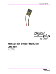
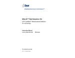
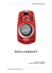
Accessory Decoder LS 100/110
1
Accessory decoders are the link between your NMRA DCC
system and your function devices (that is turnouts, signals,
uncouplers, etc.) on your model train layout.
Accessory decoders receive commands sent from the command
station via the power station and activate the drives of turnouts
or other switching devices. For DIGITAL plus systems these
switching commands are activated from input devices, such as,
hand held controller LH100, tower cab LW100, interface LI100 or
translation module LC100 (in connection with another,
compatible digital system).
+Dimensions: approximately 3.5 x 3.5” (90 x 90 mm)
LS100/110
Accessory DCC Decoder
Art. Nr. 11100 / 11110
January 1999
upgraded version 2.2
Submitted for NMRA
Conformance testing
DIGITAL plus
2
Accessory Decoder LS 100/110
Whats new in the upgraded LS100/110?
A push button and an LED have been added to the
LS100/110 to make programming easier. Direct CV mode is
now supported in service mode and a selectable flashing rate
has been added.
LED:
Whenever the LS100/110 has received information destined
for it, the LED will light up for a certain amount of time. This
allows you to very easily verify that your LS100/110 is
receiving information, and thus is correctly connected. If you,
for instance, have called up the turnout address on the hand
held controller and press the + or - keys, and keep them
pressed, then the LED will flicker or stay lit. If you release the
key, then the LED will also go out again. If this is not the case,
then you may have selected the wrong address on the LH100,
or the connection from the LV101 to the LS100/110 is not
correct.
The LED is also used as a display during programming with
the push button.
Push button:
The push button allows you to reprogram the address of an
installed LS100/110. You can also reset it to the factory
settings. The LED here serves to indicate the programming
process.
Selectable flashing rate:
In the previous version, the flashing rate was permanently
preset to 2 Hz. Now you have a range of 4 to 0.5 Hz.
available.
Special note
Accessory decoders LS100 and LS110 share this operation
manual. Unless noted, the text applies to the LS100 as well as
LS110. When describing features, connections, operational
steps, etc. that apply to only one of the accessory decoders,
only the decoder in question is named.
Accessory Decoder LS 100/110
3
Specifications of LS100/LS110
Up to 4 function devices each with a twin output can be
connected to each LS100/LS110. Power for these function
devices can by supplied by the track power or through an
external power supply. Each function device output can have its
characteristics individually set (by programming). In this way you
can program each output with a variable pulse duration, a
variable flashing operation or to a constant operation,. This
allows the direct connection of lightbulbs or LEDs without
additional relays.
The LS100 also has a connection for the feedback bus of the
DIGITAL plus system. If the feedback bus is connected, then the
position of turnouts can be sent back to the system when using
suitable turnout drives. It is then possible to display a turnout
being thrown by either DCC or by hand.
Electrical specifications:
Supply voltage:
8 - 18V
AC or pulsing DC
8 - 25V
pure DC (battery, lab power supply).
Current load capacity:
individual 1.7A continous,
output:
3 A peak (max. 20 sec.)
whole
decoder:
1.7A continous, as the sum of all
outputs.
3A peak (max. 20 sec.)
More about settings the outputs
Pulse output:
Pulse output means that the output is on (active) for at least as
long as a switching command is sent to LS100/LS110. The
switching command is for example sent to LS100/LS110 as
long as you keep the ‘+’ or ‘-’ key pressed on LH100.
The time that the function device output remains active after
releasing the key—the pulse duration—is determined by a
programmed numeric value. If during the activation time of this
DIGITAL plus
4
Accessory Decoder LS 100/110
pulse duration a new switching command is received by the
LS100/110, the output remains active for another pulse
duration.
Constant output:
By pressing the ‘+’ key on the LH100, the function device
output + is activated and remains active until the ‘-’ key is
pressed at which time the - output is activated. Thus either the
+ or - terminal of an output is active, the output operates as a
toggle switch:
For example, if you were to connect a red lightbulb of a signal
to an output’s + terminal, and the green lightbulb to the terminal, then when you press the ‘+’ key, the red lightbulb will
be on (the signal shows ‘stop’). If you press the ‘-’ key, then the
green lightbulb is on (the signal shows ‘go’). This avoids the
need to use an additional relay on light signals.
Flashing:
In this mode an output’s + and - terminals are activated
alternatingly.
This mode of operation is suited for connecting the flashing
lights at a train crossing or signal. The flashing rate is
programmable; see the section “Programming the settings of
an output” for more information.
General notes: Only one of the output pairs on an LS100/110 is
active at any one time. For example if during pulse or constant
operation the + terminal is active and the - output is activated,
then the + terminal goes inactive, regardless of whether the
pulse duration time is up or not. This applies in the
corresponding manner when the - terminal is activated first and
the + terminal is then activated.
Caution!
When programming the outputs, please note that depending on
pulse duration, or with constant operation, several outputs may
be active at the same time. With all the connected power users,
you must then not exceed the maximum total current load
capacity of 3A for the accessory decoder.
Accessory Decoder LS 100/110
5
Installing the accessory decoder LS100/LS110
Connecting the LS100/LS110 to a power station and/or
separate power supply line
Before you connect your LS100/LS110 to your NMRA DCC
system or the power supply line, you must turn off your DCC
system and disconnect the power supply (unplug the transformer
from wall outlet). There are two options for connecting your
LS100/LS110: The first option uses the power supplied by your
DIGITAL plus
6
Accessory Decoder LS 100/110
DCC system and does not use a separate power supply line to
power the LS100/110. The second option uses an external
power supply to power the LS100/110. Illustrations 1 and 2 show
the connection using the LS110. The LS100 is connected in the
same way, using the same terminals.
Illustration 1: Connecting an LS100/110 to an LV100/101 using a
separate power supply line (LS100 shown)
Illustration1 demonstrates the method of connecting an
LS100/LS110 to the track outputs of a power station. Terminals
'≈ ' are here connected in parallel with terminals J and K to
LV100/101. With this option all the power required to operate
the devices connected to the LS100/110 is supplied by the DCC
power station.
Illustration 2: Connecting an LS100/110 to an LV100/101
(LS100 shown)
Illustration 2 shows how to conect the LS100/110 to an external
power supply. Terminals K and J of the LS100/LS110 are
Accessory Decoder LS 100/110
7
Illustration 3: Connecting the feedback bus on LS100
DIGITAL plus
8
Accessory Decoder LS 100/110
connected to the corresponding terminals on a power station
LV100/LV101. Terminals ‘≈ ‘ are connected to a transformer with
16V AC.
Connecting the LS100 to the feedback bus of LZ100
(LS110 only)
Terminals R and S are connected to the corresponding terminals
on command station LZ100. Please refer to Illustration 3.
All feedback capable devices are connected in parallel to the
feedback bus, as shown. Since each device has its own
address, it does not matter in what order the devices are
connected.
Of course you can use accessory decoder LS100 and feedback
encoder LR100 in any combination. You just need to make sure
that you do not assign any address twice. Information about
shared addresses is found in the sections “Programming
address and settings of the outputs” and “Shared addresses of
LS100/110/120 and LR100” later on in this manual.
Connecting devices to the function outputs
Connecting various devices to the function outputs is shown in
illustration 4. Here are some additional explanations:
Connecting twin-coil turnout drives
The common wire of the two coils (2) is connected with terminal
‘C’. The wire from coil 1 (1) is connected with terminal ‘+’; the
one from coil 2 (3) with terminal ‘-’. Depending on the design of
the turnout drive, activating the ‘+’ terminal will result for instance
in the turnout going to the ‘diverge’ position. If that is not how
you planned it, then switch the connections at terminals
‘+’ and ‘-’.
Accessory Decoder LS 100/110
9
In the following table the common wire colors from some track
manufacturers, is matched to the wire numbers in Illustration 4.
Wire #:
1
2
3
ROCO
red
black
green
Arnold
blue
grey
purple
Fleischmann
beige
black
brown
Trix
yellow black
green
Märklin
blue
yellow
blue
Connecting light signals with lightbulbs or LEDs
If you wish to connect the outputs to lightbulbs or LEDs, then
program the corresponding outputs on LS100/LS110 to constant
on. You can then connect the lightbulbs or LEDs (using a
resistor) directly to the outputs of LS100/LS110. If you use the
separate AC supply, the digital current will not be used.
Information on programming settings is found in the section
“Programming the settings of an output” later on in this manual.
In Illustration 4 the connection of a signal’s lightbulbs is shown in
the upper left and the connection of LEDs in the lower left.
Important:
When connecting a LED, please remember that terminal ‘C’ is
positive. You must therefore connect the cathodes of the LEDs
in the signal with terminals ‘+’ and ‘-’.
When using LEDs, a current limiting resistor is necessary.
Please determine if this resistor is already installed in your LED
signal.
If that is not the case, then with a supply voltage of 16V AC you
need to use a current limiting resistor of 1.5 kOhm. If the LED is
not bright enough with that, then try lowering the resistor value
(1kOhm). If the LED is too bright, use a larger resistor value. In
the illustration this resistor is indicated with ‘R’.
DIGITAL plus
10
Accessory Decoder LS 100/110
Illustration 4: Connecting devices to the LS100/LS110 function
outputs
Accessory Decoder LS 100/110
11
Connecting a motorized turnout drive
To connect motorized turnout drives, you need adapter LA010
(Illustration 4 lower right). This adapter changes the polarity of
the motor connections to the required direction as needed.
By using this adaptor, you avoid complicated relay set-ups for
controlling a motorized drive.
For motorized drives program the outputs to pulse operation and
set the pulse duration such that the motor remains on until it
reaches the end of its stroke. With stall current turnout motors
the pulse duration can be set to constant on.
Information about programming settings is found in the section
“Programming the address and settings” later on in this manual.
Connecting the function devices to the feedback inputs of
LS100
If you use twin-coil turnouts with end-of-stroke disconnect, or a
stall current turnout motor then the connection to the feedback
input is very simple: Connect each terminal + and - with the RM
terminal next to it. For details, see illustration 5 on the left.
If your drive has separate feedback contacts, then connect it as
shown in illustration 5 on the right.
Illustration 5: Connecting the feedback inputs
DIGITAL plus
12
Accessory Decoder LS 100/110
For information on how to read the turnout position on hand held
controller LH100 or another device, please refer to the manual
for that device.
Using external control on conjunction with the LS100/110
The LS100/LS110 version 2 provides the ability to control the
function devices connected to LS100/LS110 either digitally or
with an external push button (or REED switch). This is done
using the terminal marked ‘⊥ ‘. Illustration 6 shows you how to
wire the external push buttons and/or REED switches.
Illustration 6: Connecting external controls
Accessory Decoder LS 100/110
13
It is required that the output to be optionally controlled by an
external push button not be set to flashing or constant operation
and that the function device being controlled is equipped with
end-of-stroke disconnect.
Shown is the typical twin-coil drive for signals or turnouts. The
two coils are connected with the + and - terminals on the
accessory decoder. The illustration shows LS100, on LS110
connections are made in the same manner to the same
terminals. In addition both buttons K1 and K2 are connected. If
you press button K1, then coil 1 is activated; if you press button
K2, then coil 2 is activated. This way, you can throw the turnout
(or switch the signal) digitally using LS100/LS110, or with the
buttons K1 and K2.
IMPORTANT:
The ⊥ terminals of different LS100/LS110’s must not be
connected with each other. This is not a common ground!
You must only use potential free (isolated) contacts (for
instance REED switches). The ROCO control track 42518 is
another suitable example.
Programming address and settings of outputs
First you must determine which numbers the function devices
that will be connected are to ‘listen’ to; you must program the
address of the accessory decoder. In the second step, you
determine the settings of the outputs.
Standard settings of accessory decoder LS100/LS110
From the factory LS100/LS110 is programmed to turnout
numbers 1 to 4. The outputs are set to pulse operation with the
shortest pulse duration. These settings are referred to as
standard settings.
Explanations of the turnout addresses
Note that LS100/LS110 is always programmed to a group of 4
turnout addresses. This is for example the numbers 1 to 4, 5 to
8, 9 to 12 and so on up to 253 to 256. It is not possible to
program a LS100/LS110 to the turnout numbers 3, 4, 5 and 6,
since these turnout numbers belong to two different groups.
DIGITAL plus
14
Accessory Decoder LS 100/110
The shared address area of LS100/LS110/LS120 and LR100
Information about the positions of turnouts and signals from
accessory decoder LS100/LS110 and feedback encoder LR100
occupies the same memory locations in the command station.
Information from the feedback encoder with addresses 1 to 63
overlaps information from turnouts 1 to 256.
Even non-feedback capable LS110 turnout positions have the
last command sent stored in this address area. Since no
positive feedback is available, this information may not match
the actual turnout position.
For each turnout address there are 2 feedback positions in the
command station; for each feedback encoder, there are 8
feedback positions in the command station. The overlap is
displayed in table 5.
Example:
If you have programmed an accessory decoder LS100 to
addresses 5, 6, 7 and 8, then it occupies the feedback positions
9 to 16 in the command station. You can therefore not use a
feedback encoder with address 2, since this would occupy the
same feedback numbers in the command station.
Programming the address of LS100/LS110 using the
programming button
This is a process where you can program LS100/LS110 to a
turnout address without using the programming output .
This process is suitable whenever you do not need any particular
settings for the outputs and/or the accessory decoder is already
installed and needs to be reprogrammed to another address.
You can use any device that can send a acessory decoder
command such as a LH100 hand held controller or LW100
Tower Cab.
For these instructions we assume that command station, power
station and hand held controller or tower cab all are correctly
connected with each other, and in operation (see manuals of the
devices).
Accessory Decoder LS 100/110
15
Press the programming button on the LS100/LS110 and keep it
pressed until the LED lights up and stays lit (this takes a few
seconds). Now release the button. The LED stays on. The
LS100/LS110 now will take its new address from the first DCC
accessory decoder command it receives.
To correctly program the LS100/LS110 at this point ensure that
no device is sending commands without your knowledge. These
commands could for instance come via the interface from a
computer program that is running, a switching chain from tower
cab LW100 or even from another operator on the layout.
Now intentionally generate the switching command needed for
programming:
with hand held controller LH100:
Switch LH100 over to operation mode ‘Throw turnout’ (Key
sequence F, 5). Enter one of the 4 turnout addresses in the
group that you want to program LS100/LS110 to. Confirm the
entry with the ‘enter’ key. Now press the ‘+’ or ‘-’ key on the
hand held controller and thereby send a switching command.
with tower cab LW100:
Press the red or green key of one of the 4 turnouts in the group
that you want to program LS100/LS110 to. You may need to
first set LW100 to the needed group (see the manual for
LW100). With each pressing of the red or green key, you
cause a switching command to be sent.
The turnout address sent in the switching command is now
permanently stored in the LS100/LS110. Verify that the
programming took place by observing the LED goes out and the
correct turnout is thrown (if connected). The LS100/LS110 is
now back in normal operation mode.
Programming LS100/LS110 to the standard settings using
the programming button
Press the programming button and keep it pressed. After
approximately 5 seconds the LED is lit constantly. Continue to
press the button. After another 5 seconds the LED starts
flashing. Continue to press the button pressed until the LED
turns off again. When this ocurs the operation is completed
DIGITAL plus
16
Accessory Decoder LS 100/110
Programming address and
programming output of LZ100
settings
through
the
Address and other settings of LS100/LS110 are stored in so
called “registers”, abbreviated “R”. These registers can be
imagined as a sort of notepad that can have new entries put on
them again and again. The written entries remain stored even
after the power is turned off.
Assignment of registers
LS100/LS110 has 6 registers, that are used as follows:
Reg
1
2
3
4
5
7
8
-
CV AltC
V
1 513
3 515
4 516
5 517
6 518
7 519
8 520
29 541
used for
address
settings output 1
settings output 2
settings output 3
settings output 4
version number
manufacturer ID
Configuration
allowed range of
values
1 - 256
0 - 15; 32; 33 - 47
0 - 15; 32; 33 - 47
0 - 15; 32; 33 - 47
0 - 15; 32; 33 - 47
2.2
99
128
Table 1: Assignment of registers
The value stored in R1 thus determines the address, the
‘number’ with which the connected function devices are
addressed.
R†2†to†5 behave the same: The values stored here determine
the settings of the outputs. From table 2 you see the values that
need to be entered for a desired setting of an output:
Value
Setting
0 - 15
Pulse output, variable
pulse duration
Constant output
Flashing, variable rate
32
33 - 47
Table 2: Settings of the outputs
Values other than the ones listed are not allowed and will lead to
random results.
Accessory Decoder LS 100/110
17
The pulse duration is determined by the following values:
value
0
1
2
3
4
5
6
7
pulse duration
(seconds)
0.1
0.2
0.3
0.5
0.6
0.8
1.0
1.5
pulse duration
(seconds)
2.0
3.0
4.0
6.0
8.0
10
12
15
value
8
9
10
11
12
13
14
15
Table 3: Setting pulse duration
The flashing rate is determined by the following values:
Value
33
34
35
36
37
38
39
40
flashing rate (Hz)
4
3.75
3.5
3.25
3.0
2.75
2.5
2.25
Value
41
42
43
44
45
46
47
flashing rate (Hz)
2.0
1.75
1.5
1.25
1.0
0.75
0.5
Table 4: Setting the flashing rate
The decoder version number is contained in R7. R8 contains the
manufacturer ID, which for Lenz Elektronik is 99. Both registers
can only be read, and can not be overwritten.
Connecting the LS100/LS110 to the programming output of
a command station
When the accessory decoder is to be programmed using the
programming output of the command station, we recommend
that you do all the programming before installation. For the
command station to be able to recognize successful
programming, please connect a turnout motor or a lightbulb (not
an LED!) to an output that is not set to constant on or flashing
operation. If you do not do this, you will get an error message
“ERR02” (decoder not found) on the LH100.
DIGITAL plus
18
Accessory Decoder LS 100/110
Illustration 7: Connecting LS100/LS110 to the
programming output of LZ100
To program address and settings you need your command
station LZ100, hand held controller LH100 and a transformer
with 16V AC output to supply power for LZ100. The
LS100/LS110 is programmed using the programming output of
command station LZ100. (Note any other system capable of
Direct CV mode or Register mode programming can also
sucessfuly program an LS100/LS110.)
To do this, connect terminals J and K, as well as the terminals
for the AC supply (•) of the LS100/LS110 to the programming
output (terminals P and Q) of the LZ100 command station.
Enter programming mode, as described in the manual for the
LH100.
Programming using LH100 with software version 2.1
Please proceed as follows:
On the display you see
Key
(flashes)
Confirm again with the ‘Enter’ key.
Accessory Decoder LS 100/110
19
Next LH100 will show you the most recently chosen
programming mode. Press the ‘+’ key repeatedly until the
display shows
Confirm this display with the ‘Enter’ key.
Now you must indicate which register you want to program. In
table 1 you can see which register is responsible for which
function.
Note: There is an error in the LH100 to be aware of
If you select the “CV” mode, the LH100 starts an address
search . At its completion, you receive the display "LENZ -d".
After pressing any key the address is displayed “SAD xx”,
where xx is the decoders address. If you now again press any
key other than the 'CL" key, the LH100 will show “R*_” which
is in error as the LH100 is actually still in CV mode and not in
REG mode as the display indicates. To return to REG mode,
please press the “Esc” key repeatedly until the display again
shows “PROG”, press enter and then choose the “REG”
mode using the "+" key.
Programming the turnout address
Proceed to programming mode as described above.
Let’s assume that you want to program LS100/LS110 to turnout
addresses 9, 10, 11 and 12.
Select register 1 as the register to program, since the address is
stored at this position (see table 1).
On LH100 enter one of the four turnout addresses, to which you
want to program LS100/LS110. In this example that is 9, 10, 11
or 12.
Start the programming by pressing the ‘enter’ key. LS100/LS110
will now be programmed to turnout numbers 9 to 12. Output 1
will be addressed with turnout address 9, output 2 with address
10 and so on. On the hand held controller you get the message
DIGITAL plus
20
Accessory Decoder LS 100/110
“ERR 02”. Ignore this message, since LS100/LS110 is not able
to confirm successful programming to the command station.
Neither can you read out the values stored in the memory
locations.
Programming the settings of an output
In the following examples the settings of output 1 of
LS100/LS110 are programmed. Outputs 2, 3 and 4 are
programmed in the same manner, only with the corresponding
change of the storage location.
First connect the accessory decoder to the programming output
of the command station, as described above, and change into
programming mode with the hand held controller.
Select register 3. In this position the settings of output 1 are
stored (see Table 1).
Example 1: Setting pulse operation with shortest pulse duration.
As you see from tables 2 and 3 above, you must enter the
number 1 on hand held controller LH100 as the value to be
programmed. Then start the programming with the ‘Enter” key.
Example 2: Setting to constant on:
Enter 32 as the value to be programmed on hand held controller
LH100 (see Table 2). Start the programming sequence with the
‘Enter’ key.
By entering other values from table 3, you can choose to define
the other settings.
Accessory Decoder LS 100/110
21
Table 5 Feedback addresses / turnout addresses:
F-Feedback address; T-Turnout address, FEFeedback information in the command station
F
1
2
3
4
5
6
7
8
9
10
11
12
13
14
15
16
17
18
19
20
21
22
23
24
25
26
27
28
29
30
31
32
FE
1 to 8
9 to 16
17 to 24
25 to 32
33 to 40
41 to 48
49 to 56
57 to 64
65 to 72
73 to 80
81 to 88
89 to 96
97 to 104
105 to 112
113 to 120
121 to 128
129 to 136
137 to 144
145 to 152
153 to 160
161 to 168
169 to 176
177 to 184
185 to 192
193 to 200
201 to 208
209 to 216
217 to 224
225 to 232
233 to 240
241 to 248
249 to 256
T
1 to 4
5 to 8
9 to 12
13 to 16
17 to 20
21 to 24
25 to 28
29 to 32
33 to 36
37 to 40
41 to 44
45 to 48
49 to 52
53 to 56
57 to 60
61 to 64
65 to 68
69 to 72
73 to 76
77 to 80
81 to 84
85 to 88
89 to 92
93 to 96
97 to 100
101 to 104
105 to 108
109 to 112
113 to 116
117 to 120
121 to 124
125 to 128
F
33
34
35
36
37
38
39
40
41
42
43
44
45
46
47
48
49
50
51
52
53
54
55
56
57
58
59
60
61
62
63
64
FE
257 to 264
265 to 272
273 to 280
281 to 288
289 to 296
297 to 304
305 to 312
313 to 320
321 to 328
329 to 336
337 to 344
345 to 352
353 to 360
361 to 368
369 to 376
377 to 384
385 to 392
393 to 400
401 to 408
409 to 416
417 to 424
425 to 432
433 to 440
441 to 448
449 to 456
457 to 464
465 to 472
473 to 480
481 to 488
489 to 496
497 to 504
505 to 512
T
129 to 132
133 to 136
137 to 140
141 to 144
145 to 148
149 to 152
153 to 156
157 to 160
161 to 164
165 to 168
169 to 172
173 to 176
177 to 180
181 to 184
185 to 188
189 to 192
193 to 196
197 to 200
201 to 204
205 to 208
209 to 212
213 to 216
217 to 220
221 to 224
225 to 228
229 to 232
233 to 236
237 to 240
241 to 244
245 to 248
249 to 252
253 to 256
DIGITAL plus
22
Accessory Decoder LS 100/110
Trouble shooting
Problem
Turnout does not throw, the
LED does not flicker while a
switching command is being
sent (a switching command is
always sent when you press
the ‘+’ or ‘-’ key on LH100 while
in switching mode, or when on
LW100 one of the red or green
keys is pressed).
Turnout does not throw, but the
LED flickers while a switching
command is being sent.
A called up LS100 is not shown
as a feedback capable decoder
(no R shows in the LH100
display).
When
calling
up
a
LS100/LS110 on LH100, the
following
display
shows:
When programming from
programming output of
command station, you get
message “ERR 02” on
hand held controller.
the
the
the
the
When programming from
programming output of
command station, you get
message “ERR 02” on
hand held controller.
the
the
the
the
Cause
Wrong
turnout
address
entered.
Connection between command
station and power station or
between power station and
accessory decoder is broken.
A power station has turned off
due to a short circuit or user
initiating an EMERGENCY
OFF.
External power supply is not
connected (terminals ‘≈
≈' are not
connected).
Turnout or signal drive is not
correctly connected, or is
defective.
Feedback bus is not connected
or the wires R and S are
switched.
Solution
Enter the correct turnout
address.
Check
and
correct
the
connections.
The entered address is not
occupied by an accessory
decoder, but by a feedback
encoder.
Enter the correct turnout
address.
Check
if
you
accidentally
programmed
overlapping addresses (see
“The shared address area of
LS100/LS110/LS120
and
LR100) earlier in this manual.
The command station cannot
test
for
successful
programming, since no load is
connected to the output of
LS100/LS110.
Remove cause of the short
circuit, in case of an overload,
divide the layout into several
supply sections.
Connect the power supply
(see illustrations 2 and 1).
Test
and
connections.
correct
the
Connect the feedback bus, or
correct the wires.
Connect a turnout drive or
lightbulb to one of the outputs
of LS100/LS110. See the
section
“Programming
address and settings through
the programming output of
LZ100” earlier in this manual.
Connection
between
the Test
and
correct
all
programming output of the connections.
command station (terminals P
and Q) and LS100/LS110 is not
correct.
Accessory Decoder LS 100/110
23
Lenz GmbH does everything it can do to ensure that its products
are free from defects and will operate for the life of your model
railroad equipment. From time to time even the best engineered
products fail either due to a faulty part or from accidental
mistakes in installation. To protect your investment in Digital
Plus products. Lenz GmbH offers a very aggressive 10 year
Limited Warranty.
This warranty is not valid if the user has altered, intentionally
misused the Digital Plus product, or removed the product's
protection, for example the heat shrink from decoders and other
devices. In this case a service charge will be applied for all
repairs or replacements. Should the user desire to alter a Digital
Plus Product, they should contact Lenz GmbH for prior
authorization.
Year One: A full repair or replacement will be provided to the
original purchaser for any item that that has failed due to
manufacturer defects or failures caused by accidental user
installation problems. Should the item no longer be produced
and the item is not repairable, a similar item will be substituted
at the manufacturers discretion. The user must pay for shipping
to an authorized Lenz GmbH warranty center.
Year 2 and 3: A full replacement for any item will be provided
that has failed due to manufacturer defects. If the failure was
caused by accidental user installation or use, a minimal service
charge may be imposed. Should the item no longer be produced
and the item is not repairable, a similar item will be substituted at
the manufacturers discretion. The user must pay shipping to
and from the authorized Lenz GmbH warranty center during this
portion of the warranty period.
Year 4-10: A minimal service charge will be placed on each
item that has failed due to manufacturer defects and/or
accidental user installation problems. Should the item no longer
be produced and the item is not repairable, a similar item will be
substituted at the manufacturers discretion. The user must pay
shipping to and from the authorized Lenz GmbH warranty center
during this portion of the warranty period.
DIGITAL plus
24
Accessory Decoder LS 100/110
Please contact your dealer or authorized Lenz GmbH warranty
center for specific instructions and current service charges prior
to returning any equipment for repair.
Hüttenbergstraße 29
35398 Gießen, Germany
Hotline: 06403 900 133
Fax: 06403 5332
http://www.lenz.com
Lenz Agency of North America
PO Box 143
Chelmsford, MA 01824
ph/fax: 978 250 1494
[email protected]
This equipment complies with Part 15 of FCC Rules. Operation is subject to the
following two conditions: (1) this device may not cause harmful interference, and
(2) this device must accept any interference received, including interference that
may cause undesired operation.
Please save this manual for future reference!
© 1999 Lenz GmbH, All Rights Reserved