1
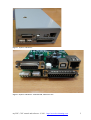
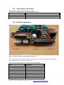
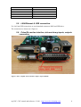
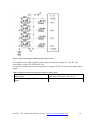
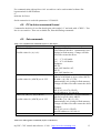
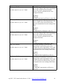
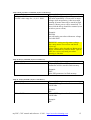
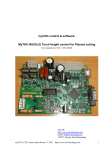
myCNC control & software. MyServo-A01 (r3) Brushless DC/AC servo motor driver & controller User manual (rev 0.02 - 2011-0525) myCNC http://www.bevelcutting.com email: [email protected] 195257, Russia, Saint-Petersburg Severny st. 73-1-91 myCNC, CNC control and software. © 2011. http://www.bevelcutting.com 1 Using This Manual This user manual provides information for proper installation of the myServo-A01 brushless DC servo motor driver & controller. WARNING: Machinery in motion can be dangerous! It is the responsibility of the user to design effective error handling and safety protection as part of the machinery. myCNC shall not be liable or responsible for any incidental or consequential damages Table of content 1 Introduction...................................................................................................................................4 2 MyServo-A01 connection.............................................................................................................4 2.1. MyServo-A01 outline...........................................................................................................4 2.2. Power supply.........................................................................................................................6 2.3. Servo motor connection........................................................................................................7 2.4. Encoder connection...............................................................................................................7 2.5. LAN/Ethernet & USB connection........................................................................................8 2.6. Pulse/Dir motion interface, drivers binary inputs, outputs connection.................................8 2.7. Opto-isolated inputs..............................................................................................................9 2.8. Connection to the control PC..............................................................................................11 3 MyServo-A01 work....................................................................................................................12 3.1. PID regulator.......................................................................................................................12 3.2. Self-study procedure...........................................................................................................12 4 Configuration and diagnostic......................................................................................................12 4.1. Connection the driver to diagnostic channel.......................................................................12 4.2. PC to driver command format............................................................................................13 4.3. Set commands.....................................................................................................................13 Table 1. myServo-A01(r3). Control Power supply. X1 pin description..........................................6 Table 2. myServo-A01(r3). Motor Power supply. X3 pin description............................................6 Table 3. myServo-A01(r3). Motor connection. X2 pin description................................................7 Table 4. myServo-A01(r3). Encoder connection. XT1 pin description...........................................7 Table 5. myServo-A01(r3) motor interface. XT2 connector pin description..................................9 Table 6. Settings for internal/external power supply for binary inputs.........................................10 Table 7. Set LAN/Ethernet commands (myServo-A01 driver).....................................................13 Table 8. Set PID regulator commands (myServo-A01 driver)......................................................13 Table 9. Run procedures commands (myServo-A01 driver).........................................................15 Table 10. Write commands (myServo-A01 driver).......................................................................15 Table 11. Print commands (myServo-A01 driver)........................................................................15 Table 12. Debug commands (myServo-A01 driver).....................................................................16 Figure 1. myServo-A01 driver.........................................................................................................5 Figure 2. myServo-A01 driver. Control board, connectors view....................................................5 Figure 3. X1-X3 connectors (Power supply and motor connection)...............................................6 Figure 4. Encoder, USB-slave and LAN/Ethernet connectors........................................................7 Figure 5. XT2 - Step/Dir motor interface, inputs, outputs, RS485..................................................8 Figure 6. Opto-isolated inputs schematic design (myServo-A01).................................................10 Figure 7. myServo-A01(r3) board, J5 & J6 location.....................................................................11 myCNC, CNC control and software. © 2011. http://www.bevelcutting.com 3 1 Introduction The myServo-A01 (r3) is intellectual servo motor driver with integrated motion control features and wide range of communication interfaces. The driver can controls AC or brushless DC servo motor with encoder as a feedback sensor. MyServo-A01 accepts PULSE/DIR signals as motion control inputs. Also the unit contains LAN/Ethernet, RS485 and USB slave interfaces to receive high-level commands and use it as motion control program. Technical specification: • Main processing unit – ARM Cortex M3 100MHz microcontroller; • Motor control PID & PWM operating frequency – 20 kHz; • Space vector modulation (Sinusoidal commutation) of motor; • IGBT based 3-phase bridge with maximum power up to 3kW; • Maximum pulse frequency – 1500 kHz; • Power supply – • 24VDC for control power; • 110-220V AC (1 or 3 phase) for motor power; • 2 transistor keys (open collector) general purpose outputs available through integrated PLC (one of them is used as “driver ready” by defaylt); • 4 opto-isolated general purpose inputs (available through PLC); • USB slave interface for configuration, programming, reflashing; • LAN/Ethernet and RS485 interface for using as one-axis motion controller (working as stand-alone control, or under myCNC software control); • Dimension: 150mm(L) x 100mm(H) x 50mm(W) Committed digital inputs can be configured as abort, jog events or can be flexibly used while machining process via PLC controller. For communication between controller and HMI software specially designed binary half-duplex master-slave protocol is used. 2 MyServo-A01 connection 2.1. MyServo-A01 outline. myCNC, CNC control and software. © 2011. http://www.bevelcutting.com 4 Figure 1. myServo-A01 driver. Figure 2. myServo-A01 driver. Control board, connectors view. myCNC, CNC control and software. © 2011. http://www.bevelcutting.com 5 2.2. Power supply. Figure 3. X1-X3 connectors (Power supply and motor connection). Two power supply are used for the driver. For control power supply is used 24V DC. For motor power is used 1 or 3 phase AC power supply. Depends on motors can be used AC voltage form 110V AC to 220VAC. Connector X1 is used for control power supply 24V DC connection. Table 1. myServo-A01(r3). Control Power supply. X1 pin description. Pin nr. 1 2 Description 24V DC GND / COMMON Table 2. myServo-A01(r3). Motor Power supply. X3 pin description. Pin nr. 1 2 3 4 Description GND / COMMON 110...220VAC ~A 110...220VAC ~B 110...220VAC ~C myCNC, CNC control and software. © 2011. http://www.bevelcutting.com 6 2.3. Servo motor connection. X2 connector is used for servo motor connection. Table 3. myServo-A01(r3). Motor connection. X2 pin description. Pin nr. 1 2 3 Description U phase V phase W phase 2.4. Encoder connection. Figure 4. Encoder, USB-slave and LAN/Ethernet connectors. XT1 connector is used for motor encoder connection. XT1 connector is pin-to-pin compatible with Fulling Motor servo drivers (ENL series) Table 4. myServo-A01(r3). Encoder connection. XT1 pin description. Pin nr. 1 2 3 4 5 6 7 8 9 Description DC +5V A B Z U V W NC (Not connected) GND myCNC, CNC control and software. © 2011. http://www.bevelcutting.com 7 10 11 12 13 14 15 /A /B /Z /U /V /W 2.5. LAN/Ethernet & USB connection. For LAN and USB connection are used standard connectors RJ45 and USB-slave. The connectors are shown on a Figure 4. 2.6. Pulse/Dir motion interface, drivers binary inputs, outputs connection. Figure 5. XT2 - Step/Dir motor interface, inputs, outputs, RS485. myCNC, CNC control and software. © 2011. http://www.bevelcutting.com 8 Table 5. myServo-A01(r3) motor interface. XT2 connector pin description Pin nr. 1 2 3 4 5 6 7 8 9 10 11 12 13 14 15 16 17 18 19 20 21 22 23 24 25 Description OUT2 OUT1 OUT3 IN1 IN2 IN3 IN4 STEP /STEP /DIR DIR RS485 A1 RS485 B1 +24V DC (for transistor outputs) +24V DC (for transistor outputs) +24V DC (for transistor outputs) (IN+24V) + 12...24V DC (for opto-isolated inputs) (IN_GND) Inputs common (-12...24V DC for opto-isolated inputs) (IN_GND) Inputs common (-12...24V DC for opto-isolated inputs) (IN_GND) Inputs common (-12...24V DC for opto-isolated inputs) (IN_GND) Inputs common (-12...24V DC for opto-isolated inputs) GND/COMMON GND/COMMON +5V DC (output power supply from the driver) GND/COMMON 2.7. Opto-isolated inputs. The driver contains 4 binary opto-isolated inputs IN1-IN4. Schematic design of binary inputs is shown below. myCNC, CNC control and software. © 2011. http://www.bevelcutting.com 9 Figure 6. Opto-isolated inputs schematic design (myServo-A01). For complete binary inputs isolation can be used external power supply 12...24V DC, that connected to contacts IN_GND & IN+24V If complete isolation don't needed, internal power supply 24V DC can be used for supply binary inputs. Table 6. Settings for internal/external power supply for binary inputs. External power supply 12…24V DC for digital inputs Internal power supply 24V DC for digital inputs J5 & J6 are open; External power supply is connected to XT2 pins 17 & (18-21) J5 & J6 are closed. myCNC, CNC control and software. © 2011. http://www.bevelcutting.com 10 Figure 7. myServo-A01(r3) board, J5 & J6 location. 2.8. Connection to the control PC. MyServo-A01(r1) controller can be connected to PC HMI through LAN/Ethernet connector XT2. Standard Ethernet cable can be used for connection. The control board may be connected either directly to the control PC or through Ethernet Switch/HUB to Local Network. For reflashing, configuration and siagnistic is used USB slave connector. myCNC, CNC control and software. © 2011. http://www.bevelcutting.com 11 3 MyServo-A01 work 3.1. PID regulator. U =Ki∗∫ dPdt Kd ∗dP Kp∗dPKv∗V Ks dt • Ki – integral coefficient; • Kp – proportinal coefficient; • Kd – differential coefficient; • Ke – EMF compensation coefficient; • Kf – frictional force compensation coefficient; All PID regulator coefficients are stored in external flash memory and can be changed via terminal programming interface. 3.2. Self-study procedure. MyServo-A01 servo drivers may works with brushless DC and AC servo motors that have 3 or 4 magnetic poles. The driver may automatically study number of poles, motor phase connection and hall-sensor connection during self-studying procedure. After the self-study procedure sucessfuly finished, all the data about shaft turning direction, hall sensor and number of poles is stored into external flash memory. During the procedure motor shaft will perform about 30 steps in both direction. The driver reads and analyzes encoder data. All procedure takes a few seconds. 4 Configuration and diagnostic. 4.1. Connection the driver to diagnostic channel. For programming, reflashing of configuring the driver should be connected to PC through USBslave connector. On Host PC should be installed drivers for USB-to-serial converter based on ftdi chip FT232RL. For Linux OS it is the kernel driver ftdi_sio. For Windows machines the drivers can be installed from myCNC folder: myCNC/driver.usb-to-serial or directly from the manufacturers website: http://www.http://www.ftdichip.com/Drivers/D2XX.htm myCNC, CNC control and software. © 2011. http://www.bevelcutting.com 12 For communication with myServo-A01 servodriver can be used terminal software like hyperterminal for MS Windows or minicom for Linux Serial connection is used with parameters 115200 8N1. 4.2. PC to driver command format. Command to the driver is text line that begins with symbol “#” and ends with <CR/LF>. Text line is case sensitive. There are available Set, Print and Debug commands. 4.3. Set commands. Table 7. Set LAN/Ethernet commands (myServo-A01 driver). Command format. #SLE {A}<CR/LF> Possible value for {A} is 0,1 #SLA {A} {B} {C} {D}<CR/LF> Possible value for {ABCD} are 0...255 #SLG {A} {B} {C} {D}<CR/LF> Possible value for {ABCD} are 0...255 Command description. [S]et [L]AN [E]nable – turn on/off LAN/Ethernet interface. Automatically save settings in flash memory. Change will take effect after restart the driver. {A} – “1” LAN enable {A} – “0” LAN disable Examples: #SLE 0 turns LAN interface off; #SLE 1 turns LAN interface on [S]et [L]AN [A]ddress – set LAN/Ethernet address of the board as given values ABCD: IP Addr ={A}.{B}.{C}.{D} Automatically save settings in flash memory. Change will take effect after restart the driver. Example: #SLA 192 168 4 78<CR/LF> sets IP address to 192.168.4.78 [S]et [L]AN [G]ateway – set LAN/Ethernet gateway as given values ABCD: GW Addr ={A}.{B}.{C}.{D} Automatically save settings in flash memory. Change will take effect after restart the driver. Example: #SLG 192 168 4 1<CR/LF> sets GW address to 192.168.4.1 Table 8. Set PID regulator commands (myServo-A01 driver). myCNC, CNC control and software. © 2011. http://www.bevelcutting.com 13 Command format. #SPP {A}<CR/LF> Possible value for {A} is 0...32000 #SPI {A}<CR/LF> Possible value for {A} is 0...32000 #SPD {A}<CR/LF> Possible value for {A} is 0...32000 #SPF {A}<CR/LF> Possible value for {A} is 0...32000 #SPE {A}<CR/LF> Possible value for {A} is 0...32000 Command description. [S]et [P]id regulator [P]roportional coeff to given value. Change takes effect immediately. New value is NOT stored in the flash memory. Special command need to store settings in the flash. Examples: #SPP 300 set PID Proportional coefficient to value 300 [S]et [P]id regulator [I]ntegral coeff to given value. Change takes effect immediately. New value is NOT stored in the flash memory. Special command need to store settings in the flash. Examples: #SPI 25 set PID Integral coefficient to value 25 [S]et [P]id regulator [D]ifferential coeff to given value. Change takes effect immediately. New value is NOT stored in the flash memory. Special command need to store settings in the flash. Examples: #SPD 1 set PID Differential coefficient to value 1 [S]et [P]id regulator [F]rictional force conpensation coefficient to given value. Change takes effect immediately. New value is NOT stored in the flash memory. Special command need to store settings in the flash. Example: #SPF 10 set PID Frictional coefficient to value 10 [S]et [P]id regulator [E]lecto Magnetic Force conpensation coefficient to given value. Change takes effect immediately. New value is NOT stored in the flash memory. Special command need to store settings in the flash. Example: #SPE 20 set PID EMF conpensation coefficient to value 20 myCNC, CNC control and software. © 2011. http://www.bevelcutting.com 14 Table 9. Run procedures commands (myServo-A01 driver). Command format. #RS {A}<CR/LF> Possible value range for {A} is 0...2000 Command description. [R]un [S]elf study procedure. The procedure will start immediately. Given value is motor voltage while step motion. After successful running all motor data will be stored in flash memory. Motor power will be turned off. To start work the driver should be restarted (reset switch or power off/on) Example: #RS 600 run selft study procedure with motor voltage Vcc*600/2000 WARNING: setting too big motor voltage may cause motor overcurrent and alarm power off. Motor voltage value depends on Motor power supply value and servo motor model. Typical value for correct self-study procedure running is 500-800. Table 10. Write commands (myServo-A01 driver). Command format. #WP <CR/LF> Command description. [W]rite [P]ID. Current PID controller parameters will be stored in flash memory Example: #WP write PID parameters in flash memory. Table 11. Print commands (myServo-A01 driver). Command format. #PP <CR/LF> #PO <CR/LF> Command description. [P]rint [P]ID regulator data. Print current PID coefficients Example: #PP [P]rint [P]ID regulator data. Print current PID coefficients. Example: #PP myCNC, CNC control and software. © 2011. http://www.bevelcutting.com 15 Table 12. Debug commands (myServo-A01 driver). Command format. #DP {A} <CR/LF> Possible value range for {A} is 0...3 Command description. [D]ebug [P]ID regulator level. Turn on PID control diagnostic with given level or turn off it Give value0 – turn off diagnostic; 1 – print position error, speed; 2 – print position error, motor voltage, speed; 3 – print position error, speed error, motor voltage, speed; Examples: #DP0 turn off diagnostic #DP1 turn on PID diagnostic with level 1 myCNC, CNC control and software. © 2011. http://www.bevelcutting.com 16