1
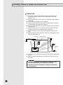
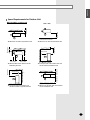
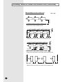
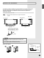
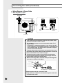
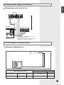
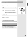
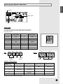
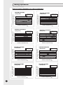
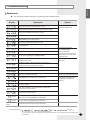
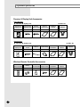
ENGLISH RUSSIAN E§§HNIKA System Air Conditioner(Cooling and Heating) DEUTSCH PORTUGUÊS ITALIANO FRANÇAIS UH052EAMC UH070EAM(1)C UH094EAM1C UH105EAMC ESPAÑOL INSTALLATION MANUAL E S F I P D G R DB98-27159A(4) Safety Precautions The following safety precautions must be taken when using your air conditioner. WARNING INSTALLING THE UNIT Risk of electric shock. • Can cause injury or death. • Disconnect all remote electric power supplies before servicing, installing or cleaning. • This must be done by the manufacturer or its service agent or a similar qualified person in order to avoid a hazard. ◆ The unit should not be installed by the user. Ask the dealer or authorized company to install the units except room air conditioners for the U.S.A and Canada area. ◆ If the unit is installed improperly, water leakage, electric shock or fire may result. ◆ Mount with the lowest moving parts at least 2.5 m above the floor or grade level. (If applicable) ◆ The manufacturer does not assume responsibility for accidents or injury caused by an incorrectly installed air conditioner. If you are unsure about installation, contact an installation specialist. ◆ When installing the built-in type air conditioner, keep all electrical cables such as the power cable and the connection cord in pipe, ducts, cable channels e.t.c to protect them against liquids, outside impacts and so on. POWER SUPPLY LINE, FUSE OR CIRCUIT BREAKER ◆ If the power cord of this air conditioner is damaged, it must be replaced by the manufacturer, its service agent or similarly qualified persons in order to avoid a hazard. ◆ The unit must be plugged into an independent circuit if applicable or connect the power cable to the auxiliary circuit breaker. An all pole disconnection from the power supply must be incorporated in the fixed wiring with a contact opening of >3mm. ◆ Do not use an extension cord with this product. ◆ If the unit is equipped with a power supply cord and a plug, the plug must be accessible after installation. ◆ The air conditioner must be installed in accordance with national wiring regulations and safety regulations wherever applicable. E-2 ENGLISH Contents ■ ■ ■ ■ ■ ■ ■ ■ ■ ■ ■ ■ ■ ■ ■ ■ ■ ■ Preparation for outdoor unit installation ............................................................... Air Conditioner and Accessories .......................................................................... Deciding where to install the outdoor unit ........................................................... Outdoor unit installation ...................................................................................... Connecting the cable ........................................................................................... Connecting the refrigerant pipe ............................................................................ Connecting up and removing air in the circuit ..................................................... Cutting / Flaring the pipes .................................................................................... Performing leak tests ........................................................................................... Connecting the drain hose to the outdoor unit ..................................................... Insulation .............................................................................................................. Using stop valve ................................................................................................... Adding refrigerant ................................................................................................. Checking correct grounding ................................................................................. Setting up option switches ................................................................................... Testing operations ................................................................................................ Troubleshooting .................................................................................................... Optional parts list ................................................................................................. 5 5 6 9 10 13 14 15 16 16 16 17 18 20 21 23 25 26 E-3 Type of outdoor unit A B C Design Model E-4 UH052EAMC UH070EAM(1)C UH094EAM1C UH105EAMC ENGLISH ENGLISH Preparation for outdoor unit installation Moving the Outdoor Unit by Wire Rope Wire rope Fasten the outdoor unit by two 8m or longer wire ropes as shown at the figure. To prevent from damage or scratches, insert a piece of cloth between the outdoor unit and rope, then move the unit. Plate protection cloth Air Conditioner and Accessories The following accessories are supplied with the air conditioner. The type and quantity may differ depending on the specifications. ◆ UH052EAMC Rubber legs Installation manual ◆ UH070EAM(1)C & UH094EAM1C Drain Plug Rubber legs Installation manual UH105EAMC Flare Nuts 3/8" Note Cap Drain A Rubber Bracket Wire Drain Plug Installation manual ◆ Refrigeration pipes and their insulating materials, power cables are not supplied. E-5 Deciding where to install the outdoor unit Outdoor Unit ◆ The outdoor unit must not be placed on its side or upside down, as the compressor lubrication oil will run into the cooling circuit and seriously damage the unit. ◆ Choose a location that is dry and sunny, but not exposed to direct sunlight or strong winds. ◆ Do not block any passageways or thoroughfares. ◆ Choose a location where the noise of the air conditioner when running and the discharged air do not disturb any neighbours. ◆ Choose a position that enables the pipes and cables to be easily connected to the indoor unit. ◆ Install the outdoor unit on a flat, stable surface that can support its weight and does not generate any unnecessary noise and vibration. ◆ Position the outdoor unit so that the air flow is directed towards the open area. ◆ Maintain sufficient clearance around the outdoor unit, especially from a radio, computer, stereo system, etc. Indoor Unit Remote Controller Stereo 1m or m ore 1m or more Fuse ore 1.5m or m Fuse re mo e or r m r mo 1.5 o m 5 1. re or mo 1.5m Outdoor Unit ◆ If the outdoor unit is installed at a height, ensure that its base is firmly fixed in position. ◆ Make sure that the water dripping from the drain hose runs away correctly and safely. CAUTION ◆ You have just purchased a system air conditioner and it has been installed by your installation specialist. ◆ This device must be installed according to the national electrical rules. E-6 ENGLISH Space Requirements for Outdoor Unit Unit : mm 2000 or more 600 or more ❋ When 3 sides of the outdoor unit are blocked by the wall 1500 or more 300 or more ❋ The upper part of the outdoor unit and the air outlet is towards the wall 300 or more 150 or more 500 or more ❋ When the air outlet is towards the wall 1500 or more 200 or more ❋ When the air outlet is opposite the wall 1500 or more 150 or more When installing 1 outdoor unit ❋ The upper part of the outdoor unit and the air outlet is opposite the wall ❋ When front and rear side of the outdoor unit is towards the wall E-7 Deciding where to install the outdoor unit (Continued) When installing more than 1 outdoor unit 1500 or more Unit : mm 200 or more ❋ When the air outlet is towards the wall 300 or more 600 or more 600 or more 600 or more 600 or more 600 or more 1500 or more 200 or more ❋ When 3 sides of the outdoor unit are blocked by the wall ❋ When front and rear side of the outdoor unit is towards the wall 1500 or more 600 or more 3000 or more 3000 or more ❋ When front and rear side of the outdoor unit is towards the wall E-8 200 or more ENGLISH Outdoor unit installation The outdoor unit must be installed on a rigid and stable base to avoid any increase in the noise level and vibration, particularly if the outdoor unit is to be installed in a location exposed to strong winds or at a height, the unit must be fixed to an appropriate support(wall or ground). Fix the outdoor unit with anchor bolts. ◆ The anchor bolt must be 20mm or higher from the base surface. Unit : mm 660 340 340 364 310 318 Anchor bolt hole Anchor bolt hole 364 Note 645 880 878 Type A,B Type C To prevent the unit against a wild animal or something, cover part after connecting the pipe. Piping CAUTION ◆ Make a drain outlet around the base for outdoor unit drainage. ◆ If the outdoor unit is installed on the roof, you have to check the ceiling strength and waterproof the unit. Outdoor Unit Support Outdoor--> Unit 20mm Anchor bolt <-- Outdoor Unit Support Base Surface E-9 Connecting the cable Two electronic cables must be connected to the outdoor unit. ◆ The connection cord between indoor unit and outdoor unit. ◆ The power cable between outdoor unit and auxiliary circuit breaker. ◆ Specially for Russian and European market, before installation, the supply authority should be consulted to determine the supply system impedance to ensure compliance. Example of Air Conditioner System When using ELB for 1 phase Power cable Communication cable Outdoor Unit 1 Communication MCCB ELB Earth Connection cord Indoor Unit ❋ If an outdoor unit is installed in a place in danger of an electric leak or submergence, you must install the ELB. E-10 ENGLISH Power Cable Specifications Type of 3 Phase B outdoor Power Max/Min unit MCCB ELB Supply (V) Power Supply Single Phase Power Power Max/Min Cable Length Supply (V) Earth Cable MCCB ELB Power Cable Length 20A 2.5mm2, 2 Wires 20m or less Ø1.6mm, 25A 3.5mm2, 2 Wires 20m or less Ø1.6mm, A - - - - - - 220240V~ /50Hz ±10% Frame: 30A Trip: 20A B,C - - - - - - 220240V~ ±10% /50Hz Frame: 30A Trip: 25A 1 Wire 1 Wire The power cable is not supplied with air conditioner. For power cable, use the grade H07RN-F or H05RN-F materials. E-11 Connecting the cable (Continued) Wiring Diagram of Power Cable When using ELB for 1 phase Power Power Supply Supply MCCB Electrical Electrical component component box box ELB MCCB Cable clamp Communication Communication Connection cord Single Phase AC220V Cable Cable Indoor Indoor Unit Unit CAUTION ◆ ◆ You You should should connect connect the the power power cable cable into into the the power power cable cable terminal terminal and and fasten fasten it it with with aa clamp. clamp. ◆ ◆ The The unbalanced unbalanced power power must must be be maintained maintained within within 2% 2% of of supply supply rating. rating. -- IfIf the the power power is is unbalanced unbalanced greatly, greatly, it it may may shorten shorten the the life life of of the the condenser. condenser. IfIf the the unbalanced unbalanced power power is is exceeded exceeded over over 4% 4% of of supply supply rating, rating, the the indoor indoor unit unit is is protected, protected, stopped stopped and and the the error error mode mode indicates. indicates. ◆ ◆ To To protect protect the the product product from from water water and and possible possible shock, shock, you you should should keep keep the the power power cable cable and and the the connection connection cord cord of of the the indoor indoor and and outdoor outdoor units units in in the the iron iron pipe. pipe. ◆ ◆ Connect Connect the the power power cable cable to to the the auxiliary auxiliary circuit circuit breaker. breaker. An An all all pole pole disconnection disconnection from from the the power power supply supply must must be be incorporated incorporated in in the the fixed fixed wiring(≥3mm). wiring(≥3mm). ◆ ◆ When When connecting connecting cables, cables, make make the the cable cable pass pass through through the the cable cable tube tube as as shown shown at at the the figure. figure. Communication cable Connection cord Power cable Cable tube Gas refrigerant pipe Liquid refrigerant pipe ◆ ◆ Must Must keep keep the the cable cable in in aa protection protection tube. tube. ◆ ◆ Keep Keep distances distances of of 50mm 50mm or or more more between between power power cable cable and and communication communication cable. cable. E-12 Connecting the cable (Continued) ENGLISH Wiring Diagram of Connection Cord Indoor Unit F3 F4 Outdoor Unit - Max. length of communication cable : 120m - Whole length of cable : 240m - Connect the Connection Cord as seen as picture, and the torque of screw is 40~70kgf·cm Connecting the refrigerant pipe Refrigerant Piping System L1 H L0 Pipe length or height Refrigerant piping system table UH052EAMC/UH070EAM(1)C/UH094EAM1C UH105EAMC Max. allowable length Actual pipe length L0 + H + L1 30m or less 50m or less Allowable height length Actual pipe length H 15m or less 30m or less E-13 Connecting up and removing air in the circuit The air in the indoor unit and in the pipe must be purged. If air remains in the refrigeration pipes, it will affect the compressor, reduce to cooling capacity and could lead to a malfunction. Refrigerant for air purging is not charged in the outdoor unit. Use Vacuum Pump as shown at the figure. Outdoor unit Indoor unit A Gas pipe side C B Liquid pipe side D 1 Connect each assembly pipe to the appropriate valve on the outdoor unit and tighten the flare nut. 2 Referring to the illustration opposite, tighten the flare nut on section B first manually and then with a torque wrench, applying the following torque. Outer Diameter Torque (kgf•cm) 6.35 mm (1/4") 140~170 9.52 mm (3/8") 250~280 12.70 mm (1/2") 380~420 15.88 mm (5/8") 440~480 19.05 mm (3/4") 990~1210 22.23 mm (7/8") 990~1210 3 Connect the charging hose of low pressure side of manifold gauge to the packed valve having a service port as shown at the figure. 4 Open the valve of the low pressure side of manifold gauge counterclockwise. 5 Purge the air from the system using vacuum pump for about 10 minutes. ◆ Close the valve of the low pressure side of manifold gauge clockwise. ◆ Make sure that pressure gauge show -0.1MPa(-76cmHg) after about 10 minutes. Vacuum pump This procedure is very important in order to avoid gas leak. ◆ Turn off the vacuum pump. ◆ Remove the hose of the low pressure side of manifold gauge. B(liquid) 6 Set valve cork of both liquid side and gas side of packed valve to the open position. 7 Mount the valve stem nuts and the service port cap to the valve, and tighten them at the torque of 183kgf•cm with a torque wrench. 8 Check for gas leakage. ◆ At this time, especially check for gas leakage from the 3-way valve’s stem nuts(A port), and from the service port cap. Valve stem E-14 ENGLISH Cutting / Flaring the pipes 1 Make sure that you have the required tools available (pipe cutter, reamer, flaring tool and pipe holder). 2 If you wish to shorten the pipes, cut it with a pipe cutter, taking care to ensure that the cut edge remains at a 90° angle with the side of the pipe. Refer to the illustrations below for examples of edges cut correctly and incorrectly. 90 O Oblique Rough Burr 3 To prevent any gas from leaking out, remove all burrs at the cut edge of the pipe, using a reamer. 4 Slide a flare nut on to the pipe and modify the flare. Outer Diameter(D) 6.35 mm (1/4") 9.52 mm (3/8") 12.70 mm (1/2") 15.88 mm (5/8") 19.05 mm (3/4") 22.23 mm (7/8") 5 Check that the flaring is correct, referring to the illustrations below for examples of incorrect flaring. Inclined 6 Depth (A) 1.3mm 1.8mm 2.0mm 2.2mm 2.2mm 2.2mm Damaged Surface Cracked Uneven Thickness Align the pipes and tighten the flare nuts first manually and then with a torque wrench, applying the following torque. Outer Diameter 6.35 mm (1/4") 9.52 mm (3/8") 12.70 mm (1/2") 15.88 mm (5/8") 19.05 mm (3/4") 22.23 mm (7/8") Torque (kgf•cm) 140~170 250~280 380~420 440~480 990~1210 990~1210 CAUTION ◆ In case of welding the pipe, you must weld with nitrogen gas blowing. E-15 Performing leak tests Before completing the installation (insulation of the hose and piping), you must check that there are no gas leaks. B To check for gas leaks on the... Then, using a leak detector, check the... Outdoor unit Valves on sections A and B. A Connecting the drain hose to the outdoor unit When using the air conditioner in the heating mode, ice may accumulate. During de - icing, the condensed water must be drained off safely. Consequently, you must install a drain hose on the outdoor unit, following the instructions below. 1 Make space more than 50mm between the bottom of the outdoor unit and the ground for installation of the drain hose, as shown in figure. 2 Insert the drain plug into the hole on the underside of the outdoor unit. 3 Connect the drain hose to the drain plug. 4 Ensure that the drained water runs off correctly and safely. 50mm min. 30mm Insulation Once you have checked that there are no leaks in the system, you can insulate the piping and hose. No gap 1 To avoid condensation problems, place an insulator around each refrigerant pipe. Note ◆ When insulate the pipe, be sure to overlap the insulation. ◆ You have to use more than 120°C insulation(T13.0 or thicker Acrylonitrile Butadien Rubber) for the gas refrigerant pipe. NBR(T13.0 or thicker) E-16 ENGLISH Using stop valve To Open the Stop Valve 1 Open the cap and turn the stop valve counterclockwise by using a hexagonal wrench. 2 Turn it until the axis is stopped. Note ◆ Do not apply excessive force to the stop valve and always use special instruments. Otherwise, the stopping box can be damaged and the back sheet can leaks. ◆ If the watertight sheet leaks, turn the axis back by half, tighten the stopping box, then check the leakage again. If there is no leakage any more, tighten the axis entirely. 3 Cap Service port Axis Sealing point Tighten the cap securely. To Close the Stop Valve 1 Remove the cap. 2 Turn the stop valve clockwise by using a hexagonal wrench. 3 Tighten the axis until the valve reached the sealing point. 4 Tighten the cap securely. CAUTION ◆ When you use the service port, always use a charging hose, too. ◆ Check the leakage of refrigerant gas after tightening the cap. ◆ Must use a spanner and wrench when you open/tighten the stop valve. E-17 Adding refrigerant The outdoor unit is loaded with sufficient refrigerant for the standard piping. Thus, refrigerant must be added if the piping is lengthened. This operation can only be performed by a qualified refrigeration specialist. For quantity of adding refrigerant, refer to page 19. 1 Check that the stop valve is closed entirely. 2 Charge the refrigerant through the service port of liquid stop valve. Note 3 ◆ Do not charge the refrigerant through the gas side service port. If you cannot charge the refrigerant according to the upper steps, following these: 3-1 Open both liquid stop valve and gas stop valve. 3-2 Operate the air conditioner by pressing the K2 key on the outdoor unit PCB. 3-3 About 30 minutes later, charge the refrigerant through the service port of gas stop valve. Note ◆ If necessary, refer to the pressure table classified by outdoor temperature. Outdoor unit Liquid side stop valve(service port) Gas side stop valve(service port) Ref. Indoor unit Balance E-18 Vacuum pump 1 2 ENGLISH How to Calculate the Quantity of Adding Refrigerant How Calculate Quantity AddingforRefrigerant If you haveto used more thanthe 7.5m, add “Q”ofof refrigerant extrameter (For maximum piping length and height,refer to page 13) The quantity of additional refrigerant is variable according to the installation situation.Thus,make sure the outdoor unit situation before adding refrigerant.This operation can only be performed by a qualified refrigeration specialist. M odel “Q” (R410A) UH052EAMC 25 g/m UH070EAM(1)C 40 g/m UH094EAM1C 60 g/m UH105EAMC 70 g/m Piping length “a” Additional charging amount UH052EAMC UH070EAM(1)C UH094EAM1C UH105EAMC - - - 7.5m - 10.0m 62.5g 100g 150g 175g 15.0m 187.5g 300g 450g 525g ❋ For example of UH052EAMC,if pipe length is 10.0m ,you would calculate (10.0-7.5)*25=62.5 Important information regulation regarding the refrigerant used Thisproduct productcontains containsfluorinated fluorinatedgreenhouse greenhousegases gasescovered coveredbybythe theKyoto Kyoto This Protocol.Do Donot notvent ventgases gasesinto intothe theatmosphere. atmosphere. Protocol. Pleasefillfillininwith withindelible indelibleink, ink, Please the factory refrigerant chargeofofthe theproduct, product, - the factory refrigerant charge the additional refrigerant amount charged thefield fieldand and - the additional refrigerant amount charged ininthe + the total refrigerant charge. - + the total refrigerant charge. onthe therefrigerant refrigerantcharge chargelabel labelsupplied suppliedwith withthe theproduct. product. on Note a. Factory refrigerant charge of the product: see unit name plate b. Additional refrigerant amount charged in the field (Refer to the above information for the quantity of refrigerant replenishment.) c. Total refrigerant charge d. Refrigerant cylinder and manifold for charging Refrigeranttype type Refrigerant R410A R410A GWP=Global Warming Potential GWP=Global Warming Potential Contains fluorinated greenhouse gases covered by the Kyoto Protocol. Indoor unit d a = ( = ( b The filled-out label must be adhered in the proximity of the product The filled-out label must be adhered in the proximity of the product chargingport port(e.g. (e.g.onto ontothe theinside insideofofthe thestop stopvalve valvecover). cover). charging GWPvalue value GWP 1975 1975 ) kg ) kg Outdoor unit + = ( ) kg c E-19 Checking correct grounding If the power distribution circuit does not have an earth or the ground does not comply with specifications, an grounding electrode must be installed. The corresponding accessories are not supplied with the air conditioner. Carbon plastic Steel core PVC-insulated green/ yellow wire 1 Select an grounding electrode that complies with the specifications given in the illustration. 2 Determine a suitable location for the grounding electrode: ◆ In damp hard soil rather than loose sandy or gravel soil that has a higher grounding resistance ◆ Away from underground structures or facilities, such as gas pipes, water pipes, telephone lines and underground cables ◆ At least two metres away from a lightening conductor grounding electrode and its cable Terminal M4 To grounding screw 50cm Note 30cm 3 Finish wrapping insulating tape around the rest of the pipes leading to the outdoor unit. 4 Install a green/yellow coloured grounding wire: ◆ If the grounding wire is too short, connect an extension lead, in a mechanical way and wrapping it with insulating tape (do not bury the connection) ◆ Secure the grounding wire in position with staples Note E-20 ◆ The grounding wire for the telephone line cannot be used to ground the air conditioner. ◆ If the grounding electrode is installed in an area of heavy traffic, its wire must be connected securely. 5 Carefully check the installation, by measuring the grounding resistance with a ground resistance tester. If the resistance is above required level, drive the electrode deeper into the ground or increase the number of grounding electrodes. 6 Connect the grounding wire to the electrical component box inside of the outdoor unit. ENGLISH Setting up option switches Display Rotary switch KEY Rotary Switch You should display that how many indoor units are connected to the outdoor unit. Refer to the table below, then turn the arrow to appropriate position. Switch No. Number of indoor unit(s) Switch No. Number of indoor unit(s) 0 or 1 One 9 Nine 2 Two A Ten 3 Three B Eleven 4 Four C Twelve 5 Five D Thirteen 6 Six E Fourteen 7 Seven F Fifteen 8 Eight - - KEY K1 K2 CHECK MODE RESET DIS 1 K4 K3 DIS 2 Display DISPLAY MODE ITEM NO. CURRENT DATA DISPLAY Summary of KEY functions Number of press times Function K1 K2 K3 K4 (Displayed on SEG 3, 4) (Displayed on SEG 3, 4) (Displayed on SEG 3, 4) (Displayed on SEG 3, 4) 1 Adding refrigerant at heating mode Adding refrigerant at cooling mode Reset Displays data 2 Test operation at heating mode Test operation at cooling mode - - 3 End Pump Down for recovery of refrigerant - - 4 - End - - ❊ Use the K1 only for heat pump models. E-21 Setting up option switches (Continued) Reading data indicated on the display KEY Number of press K1 1 Adding refrigerant for heating mode 2 Test operation for heating mode 3 End 1 Adding refrigerant for cooling mode 2 Test operation for cooling mode 3 Pump Down for recovery of refrigerant 4 End K2 K3 K4 Item Example Display Meaning Reset 1 Discharge temperature of compressor 2 Temperature of outdoor heat exchanger 38 °C 3 Outdoor temperature 34 °C 4 Step of electronic expansion valve (0 step : all closed, 480 step : all open) 5 Temperature of evaporator 110 °C 120STEP (12 x 10) -2 °C 12 °C E-22 6 Indoor temperature 7 Stopping view mode & display communication data 22 °C ENGLISH Testing operations 1 Check the power supply between the outdoor unit and the auxiliary circuit breaker. Single phase power supply: L, N 2 Check the indoor unit. 2-1 Check that you have connected the power and communication cables correctly. (If the power cable and communication cables one mixed up or connected incorrectly, the PCB will be damaged.) 2-2 Check the thermistor sensor, drain pump/hose, and display are connected correctly. 3 Connect the outdoor unit to your computer where the provided software is installed, then supply power to the outdoor unit. 4 If the outdoor unit is powered on, it will start tracking to check user's option(s) and number of indoor unit. - At this time, the SEG 1 and SEG 2 on outdoor unit PCB display the number of indoor unit registered and the SEG 3 and SEG 4 display the number of indoor units which responded. - If an error mode is displayed, fix the error according to the service manual. 5 Check the thermistor sensor, electronic expansion valve by using the computer. 6 Press K2 on the outdoor unit PCB. - If you press K2, the compressor starts operation. Operate the compressor for 20 minutes, then add refrigerant according to the graph shown on page 18~19. - If you press K2 again, test operation is started. - If you don't stop the operation of adding refrigerant, it will be stopped automatically after 1 hour. - If you don't stop test operation, it will be stopped automatically after 1 hour. - If K2 is pressed during the operation of adding refrigerant, test operation is started without compressor stopping. Therefore, start test operation after the operation of adding refrigerant. - The compressor can be operated after completely 3-minute preparation and tracking. - When testing operations at Heating Mode, press K1 instead of K2. 7 Check that indoor and outdoor temperatures, step of electronic expansion valve and operation of compressor by using the computer. 8 Check that there is any error mode in the outdoor unit PCB during the test. - You should test operations for more than 30 minutes. - Check that the water dripping from the drain hose runs away correctly and safely. 9 To complete the test, press the test operation KEY(K2) again. E-23 Testing operations Graph of pressure depending on outdoor temperature 8.9 8.99 8.6 8.39 15 20 25 30 35 Low pressure (Kgf/cm2G) UH070EAM(1)C/EH070EAM(1)C ( Cooling mode ) 10.0 9.8 9.6 9.4 9.2 9.0 8.8 8.6 8.4 8.2 8.0 9.73 9.29 Low pressure (Kgf/cm2G) 9.58 9.1 8.68 8.5 15 20 25 30 35 40 45 Outdoor temperature 7.5m( Pipe length ) 30 m(Pipe length) 10.0 9.5 9.0 8.5 8.68 8.17 8.36 8.1 8.0 7.5 7.6 7.8 7.0 6.5 6.0 15 20 25 30 35 40 45 Outdoor temperature DH105EAMC/UH105EAMC (Cooling mode ) Low pressure (Kgf/cm2G) 45 7.5m( Pipe length ) 30 m( Pipe length) UH094EAM1C/DH094EAMC (Cooling mode ) E-24 40 Outdoor temperature 10.0 9.8 9.6 9.4 9.2 9.0 8.8 8.6 8.4 8.2 8.0 7.5m( Pipe length ) 30 m(Pipe length) 9.58 9.16 8.99 8.95 8.44 8.25 15 20 25 30 35 Outdoor temperature 40 45 Low pressure (Kgf/cm2G) 9.19 9.2 9.0 8.8 8.6 8.4 8.2 8.0 9.2 38 36 34 32 31.48 30 28 24.99 26 24 24.41 22 20 5 -5 -15 -10 0 7.5m (Pipe length ) 30 m(Pipe length) 35.49 33.49 33.24 31.23 29.31 20 15 10 30 25 Outdoor temperature UH070EAM(1)C/EH070EAM(1)C ( Heating mode ) Low pressure (Kgf/cm2G) 9.6 9.4 UH052EAMC/EH052EAMC (Heating mode ) 36 34 32 7.5m (Pipe length ) 30 m( Pipe length) 32.37 30.56 29.75 30 28 26 28.95 27.42 24 25.98 21.89 22 21.6 20 -15 -10 -5 5 0 10 20 15 25 30 Outdoor temperature UH094EAM1C/DH094EAMC (Heating mode ) Low pressure (Kgf/cm2G) 7.5m( Pipe length ) 30 m(Pipe length) 36 34 32 24 32.93 30.84 30 28 26 7.5m (Pipe length ) 30 m(Pipe length) 32.3 30.4 28.50 28.43 24.16 22 20 -15 -10 22.8 -5 5 0 10 20 15 25 30 Outdoor temperature DH105EAMC/UH105EAMC (Heating mode ) Low pressure (Kgf/cm2G) Low pressure (Kgf/cm2G) UH052EAMC/EH052EAMC (Cooling mode ) 38 36 34 32 30 28 26 24.21 24 22 20 21.41 18 -10 -5 30.36 7.5m( Pipe length ) 30 m(Pipe length) 34.4 32.55 29.95 27.65 0 5 10 15 Outdoor temperature 20 32.06 25 30 ENGLISH Troubleshooting Outdoor unit ◆ If an error occurs during the operation, it is displayed on the outdoor unit PCB. Display Explanation High temperature of Discharge (Protection control) Remark Error about protection control of outdoor unit High temperature of outdoor heat exchanger (Protection control) Low pressure of outdoor (Protection control) Reverse phase error (Protection control) COMP DOWN to protect being frozen Instant power supply failure (Power on/ off) In removing frost Errors about outdoor unit sensor (OPEN/SHORT) Error of temperature sensor in outdoor heat exchanger (OPEN/SHORT) Detection during the operation of indoor unit (Sensing and sending errors into the comError of Discharge TEMP sensor (OPEN/SHORT) munication data) System Down caused by communication error after Communication and indoor unit errors completion of tracking Mismatching of the indoor unit numbers set with those Error of OUT TEMP sensor (OPEN/SHORT) communicated after completion of tracking Error of float switch in indoor unit Error of setting option switches for optional accessories Indoor units communication error Indoor units communication error OPEN/SHORT error of room sensor in indoor unit Self-diagnosis of indoor and outdoor unit (x:indoor unit address) OPEN/SHORT error of eva in sensor in indoor unit Error of fan starting Open error of electronic expansion valve in outdoor unit (Detected once or more times) Close error of electronic expansion valve in outdoor unit (Detected once or more times) (Detected once or more times) Flicker Flicker K1, K2, K3, K4, K5 Flicker Displays of operating status Below -5°C when cooling (Outdoor temperature) Over 30°C when heating (Outdoor temperature) Displays of Key mode and emergency operating The order of priority : E6 P4 9 tu to G4 G5 E3 qx rx vx K1, K2, K3, K4, K5 - In case that the same error displays from multi-indoor units, the one having the faster address has the priority. E-25 Optional parts list Receiver & Display Unit Accessories Concealed type ◆ Receiver & display unit Receiver & display unit 1 ◆ Wire kit STS 2S-2x10 2S-4x12 tapped screw tapped screw 4 2 Owner’s instructions Installation manual Wire kit 1 1 1 Standard type ◆ Receiver & display unit ◆ Wire kit Receiver & display unit M4x16 tapped screw Cable-tie Cable clamp Owner’s instructions Installation manual Wire kit 1 7 2 5 1 1 1 Owner’s instructions Installation manual 1 1 Wireless Remote Controller Accessories E-26 Wireless remote controller Battery 1 2 Remote STS 2S-2x10 control holder tapped screw 1 2 ENGLISH Wired Remote Controller Accessories M4x16 tapped Indoor unit power screw drawing cable Wired remote controller Cable-tie Cable clamp 1 2 5 7 1 Wire joint Owner’s instructions Installation manual 1 1 1 Communication cable of the wired remote controller 1 Centralized Controller Accessories Centralized controller Cable-tie Cable clamp M4x16 tapped screw Owner’s instructions Installation manual 1 2 5 7 1 1 Function Controller Accessories Function controller Cable-tie Cable clamp M4x16 tapped screw Owner’s instructions Installation manual 1 2 6 7 1 1 E-27 Optional parts list (Continued) Transmitter Accessories Transmitter Transmitter power cable Transmitter communication cable Installation manual 1 1 1 1 ◆ If you would like to install the centralized controller, Note you must install the transmitter in the outdoor unit. 7-day Scheduler Accessories E-28 7-day Scheduler Cable-tie Cable clamp M4x16 tapped screw Owner’s instructions Installation manual 1 2 2 4 1 1 ENGLISH Memo E-29