1
Advanced Dome Controller
ADTT16E
Operator’s Manual
8200-0306-02 A1
ADTT16E Advanced Dome Controller
Operator’s Manual
Version
0701-2833-0103 (EEPROM)
0701-2834-0201 (Flash PROM)
Thank you for using American Dynamics products. We support our products through an extensive and
worldwide network of dealers. The dealer, through whom you originally purchased this product, is your
point of contact if you have a need for service or support. Our dealers are fully empowered to provide the
very best in customer service and support. Dealers should contact American Dynamics at (800) 507–6268 or
(561) 912-6259 or on the web at www.americandynamics.net.
EQUIPMENT MODIFICATION CAUTION
Equipment changes or modifications not expressly approved by Sensormatic Electronics Corporation, the
party responsible for FCC compliance, could void the user's authority to operate the equipment and could
create a hazardous condition.
FCC COMPLIANCE
This equipment complies with Part 15 of the FCC rules for Class A digital devices when installed and used
in accordance with the instruction manual. Following these rules provides reasonable protection against
harmful interference from equipment operated in a commercial area. This equipment should not be installed
in a residential area as it can radiate radio frequency energy that could interfere with radio communications,
a situation the user would have to fix at their own expense.
WARRANTY DISCLAIMER
Sensormatic Electronics Corporation makes no representation or warranty with respect to the contents
hereof and specifically disclaims any implied warranties of merchantability or fitness for any particular
purpose.
NOTICE: The information in this manual was current when published. The manufacturer reserves the right
to revise and improve its products. All specifications are therefore subject to change without notice.
LIMITED RIGHTS NOTICE
For units of the Department of Defense, all documentation and manuals were developed at private expense
and no part of it was developed using Government Funds. The restrictions governing the use and disclosure
of technical data marked with this legend are set forth in the definition of “limited rights” in paragraph (a)
(15) of the clause of DFARS 252.227.7013. Unpublished - rights reserved under the Copyright Laws of the
United States.
TRADEMARK NOTICE
Touch Tracker, American Dynamics, and the American Dynamics logo are trademarks or registered
trademarks of Sensormatic Electronics Corporation. Other product names mentioned herein may be
trademarks or registered trademarks of Sensormatic or other companies.
COPYRIGHT NOTICE
Under copyright laws, the contents of this manual may not be copied, photocopied, reproduced, translated
or reduced to any electronic medium or machine-readable form, in whole or in part, without prior written
consent of Sensormatic Electronics.
SOFTWARE LICENSE AGREEMENT
A Software License Agreement appears in Appendix A of this manual. Please read it carefully. Using the
ADTT16E system software indicates that you accept the terms and conditions of this agreement.
Copyright 2004
All rights reserved.
PN- 8200-0306-02, Rev. A1 (BSL 03/2004)
TABLE OF CONTENTS
PREFACE: BEFORE YOU BEGIN .....................................................................................................................V
Using This Manual ...........................................................................................................................................vi
Text Conventions.............................................................................................................................................vi
Related Documents ........................................................................................................................................vii
Support Services ........................................................................................................................................... viii
CHAPTER 1: GETTING STARTED WITH THE ADTT16E ADVANCED DOME CONTROLLER ................. 1-1
What is the ADTT16E Advanced Dome Controller? .................................................................................... 1-2
Equipment Overview..................................................................................................................................... 1-3
System Features........................................................................................................................................... 1-4
Controller Features ....................................................................................................................................... 1-5
Controller Operating Modes ......................................................................................................................... 1-6
What To Do Next .......................................................................................................................................... 1-9
CHAPTER 2: CHANGING CONFIGURATION SETTINGS............................................................................. 2-1
Setting the Language for Prompts and Messages ....................................................................................... 2-2
Setting Up Primary versus Secondary Controllers ....................................................................................... 2-3
Configuring the External System .................................................................................................................. 2-5
Using Passwords to Restrict System Access............................................................................................... 2-6
CHAPTER 3: OPERATING THE ADTT16E ADVANCED DOME CONTROLLER ........................................ 3-1
Logging On / Off the ADTT16E Controller.................................................................................................... 3-2
Monitor Display Formats............................................................................................................................... 3-3
Selecting and Controlling Cameras .............................................................................................................. 3-6
SpeedDome Peel and Flip Features ..........................................................................................................3-11
Displaying Quick Views ..............................................................................................................................3-12
Running Patterns ........................................................................................................................................3-13
Running the Controller Sequence ..............................................................................................................3-15
Controlling Dome Outputs ..........................................................................................................................3-16
Clearing System Alarms .............................................................................................................................3-17
CHAPTER 4: PROGRAMMING CONTROLLER FUNCTIONS ......................................................................4-1
Programming Quick Views ........................................................................................................................... 4-2
Programming Patterns.................................................................................................................................. 4-3
Programming the Controller Sequence ........................................................................................................ 4-5
Configuring System Alarms .......................................................................................................................... 4-8
SpeedDome LT Auto Pan Programming ....................................................................................................4-11
CHAPTER 5: QUEST MULTIPLEXER SUPPORT.......................................................................................... 5-1
What is the MultiVision Quest Triplex Multiplexer? ...................................................................................... 5-2
Using the Controller to Access Multiplexer Functions.................................................................................. 5-3
Changing the Multiplexer Display Format .................................................................................................... 5-4
Using the Multiplexer Digital Zoom............................................................................................................... 5-6
Working with Freeze Frame and Freeze Field Modes ................................................................................. 5-7
Working with the Multiplexer Sequence ....................................................................................................... 5-7
CHAPTER 6: USING SYSTEM UTILITIES AND SOLVING PROBLEMS ............................................................. 6-1
What are System Utilities? ........................................................................................................................... 6-2
Working with Dome Utilities.......................................................................................................................... 6-2
Working with Controller Utilities.................................................................................................................... 6-7
Solving Problems........................................................................................................................................6-10
APPENDIX A: SOFTWARE LICENSE AGREEMENT................................................................................... A-1
GLOSSARY
INDEX
N O T E S :
iv
ADTT16E Advanced Dome Controller Operator's Manual
PREFACE
Before You Begin
This operator’s manual provides information about the ADTT16E advanced dome controller
features and operation. It explains how to use the controller (Touch Tracker) to program and
operate the CCTV system. It is designed to be a continuing source of information and
reference while using the controller.
In This Chapter
•
•
•
•
Using This Manual................................................................................................................... vi
Text Conventions ..................................................................................................................... vi
Related Documents ................................................................................................................. vii
Support Services .................................................................................................................... viii
Using This Manual
This manual covers the following topics:
Chapter 1
Getting Started with the ADTT16E Advanced Dome Controller:
Provides an overview of the ADTT16E controller. It explains the
different operating modes that may be experienced when using the
controller. In addition, it explains how to access and use the
controller menus to configure and program your controller.
Chapter 2
Changing Configuration Settings: Describes the various settings
that should be configured before performing other operating tasks.
Chapter 3
Operating the ADTT16E Advanced Dome Controller: Explains
how to control the devices used with your system. It explains how
start Quick Views, Patterns, and the Controller Sequence to
automate surveillance activities. In addition, it explains how to the
clear dome alarms configured for your system.
Chapter 4
Programming Controller Functions: Provides instructions for
programming Quick Views, Patterns, the Controller Sequence, and
dome alarms used to automate surveillance.
Chapter 5
Quest Multiplexer Support: Describes how to use the controller to
access the advanced features offered by the Quest triplex
multiplexer.
Chapter 6
Using System Utilities and Solving Problems: Describes the dome
and controller utilities that are started from the menu. In addition,
troubleshooting procedures are provided should problems be
encountered with the system or its components.
Appendix A
Software License Agreement: Explains the terms and conditions for
using this product
Text Conventions
This book uses text in various ways to identify different kinds of information.
vi
Italics
Used for terms specific to the Advanced Dome Controller and
other text requiring emphasis.
Monospace
Used for LCD messages and prompts. For example,
Select Language.
Bold
Used for names of buttons on the keypad. For example, View.
ADTT16E Advanced Dome Controller Operator's Manual
Notes
Special notes appear inside a box similar to this one. The icon represents the
information type presented.
Special operating notes
Tips for operating the system
Shortcuts for programming tasks
Important system operating information
Related Documents
Other sources provide supplemental information about using the ADTT16E.These sources
serve to enhance your understanding of the system and its applications.
• The Quick Reference Guide (document number 8200-0306-03) provides information
about the most commonly used features of the advanced dome controller. This document
should be used as a supplement to—not in place of—the information covered in this
manual.
• The Programming Worksheets (document number 8200-0306-04) provides worksheets
to simplify the task of programming your system. Worksheets for Quick Views, Patterns,
Controller Sequence, Inputs/Outputs and Alarm Programming are included.
• Some ADTT16E systems are installed with a quad processor. The quad processor’s
features can supplement the functionality of your system. Refer to the quad processor
instructions for more information.
• Some ADTT16E systems are installed with a multiplexer. The multiplexer's features can
supplement the functionality of your system. Refer to the multiplexer instructions for
more information.
• Some ADTT16E systems are connected to a video recorder. Refer to the video recorder
instructions for more information.
Contact your sales representative if you need additional copies of the Operator's Manual or
any other support documentation. The part number for this manual is 8200-0306-02; use this
number when ordering additional copies.
Preface
vii
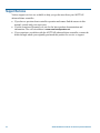
Support Services
Various support services are available to help you get the most from your ADTT16E
advanced dome controller.
• If you have a question about controller operation and cannot find the answer in this
manual, consult with your supervisor.
• Visit the American Dynamics web site for the latest product documentation and
information. The web site address is www.americandynamics.net.
• If you experience a problem with the ADTT16E advanced dome controller, contact the
dealer through whom you originally purchased this product for service or support.
viii
ADTT16E Advanced Dome Controller Operator's Manual
CHAPTER 1
Getting Started with the ADTT16E Advanced Dome
Controller
This chapter provides an overview of the ADTT16E advanced dome controller. It describes
the controller features and explains the different operating modes that may be experienced
when using the controller. In addition, it explains where to find additional information for
using your system.
In This Chapter
•
•
•
•
•
•
What is the ADTT16E Advanced Dome Controller? ............................................................ 1-2
Equipment Overview ............................................................................................................. 1-3
System Features ..................................................................................................................... 1-4
Controller Features................................................................................................................. 1-5
Controller Operating Modes .................................................................................................. 1-6
What To Do Next................................................................................................................... 1-9
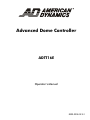
What is the ADTT16E Advanced Dome Controller?
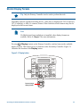
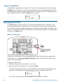
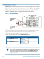
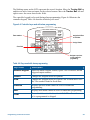
The ADTT16E advanced dome controller is a video security system that supports the
programming and recall of automated system functions, such as Quick Views, Patterns, and
the Controller Sequence. The standard configuration consists of one or two controllers
(Touch Trackers), a multiplexer or other video-switching device, monitors, a recording
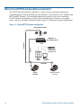
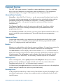
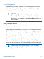
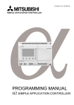
device, and up to 64 domes and fixed cameras. Figure 1-1 illustrates a typical configuration.
Figure 1-1: Typical ADTT16E system configuration
Fixed Cameras & Domes
Video
Video
RS-232
SensorNet
Multiplexer or
other switching device
Optional VCR or
Digital Recorder
Main
Monitor
Optional
Call Monitor
SensorNet
A
A
B
B
Pe
Pe
el
O ut
Cl
pu t
1
On
O ff
5
8
n
D
3
Me nu
O ut
Cl
Fl ip
6
7
ose
O pe
C
2
4
ea r
I r is
Cl
el
I nfo
I nf o
M e nu
V ie
w
Pa t
t er n
Re pea
t
Patt
er n
9
0
pu t
e
1
8
n
D
3
Fl ip
6
7
O pe
C
2
4
5
I r is
Clos
On
O ff
ea r
V ie
Pre
vi ous
Primary
Controller
1-2
S eq
Pre
N ext
w
Pa t
t er n
Re pea
t
Pa t
t er n
9
0
S eq
vi ous
N ext
Optional Secondary
Controller
ADTT16E Advanced Dome Controller Operator's Manual
Equipment Overview
The ADTT16E system consists of controllers, cameras and domes, monitors, a switching
device, such as a multiplexer or quad splitter, and recording devices. This equipment is
illustrated in Figure 1-1 on page 1-2. Descriptions of the components follow.
Advanced Dome Controllers
Controllers—also called Touch Trackers— are the system control keyboards used to select
the cameras, perform programming and configuration tasks, acknowledge alarms, and run
automated system tasks. By installing two controllers—a Primary Controller and a
Secondary Controller— two operators can perform system surveillance functions
simultaneously.
The Primary Controller is used as the main system keyboard. It interfaces with the
multiplexer or other video-switching unit and provides system administration and
programming functions.
The Secondary Controller is the alternate system keyboard. When installed, this allows two
users to operate the system simultaneously. It provides limited system programming
functions.
Cameras and Domes
Cameras and domes enable you to monitor activity throughout the facility from a single
location. The system is compatible with programmable and non-programmable domes,
Viewer 360° imaging systems, and fixed cameras.
Monitors
Monitors are used to display video from the cameras and domes. You may have monitors for
each camera installed, or you may have monitors connected to the switching unit.
The main monitor is used to display video in multi-window 4-, 9-, or 16-camera format, or
display the currently selected camera in full-screen format. The Primary Controller operates
the main monitor. The call monitor is used to display video from the currently selected
camera in full-screen format only. The Secondary Controller operates the call monitor.
Switching Device
Video-switching units, such as quad processors and multiplexers allow you to connect
multiple cameras and domes to a single unit and view video on a connected monitor.
Depending on the device, 4, 9, or 16 cameras can be connected.
If a Multivision Quest triplex multiplexer is used, the system provides access the multiplexer
features using the controller for improved system functionality.
Recording Device
VCRs or digital recorders keep a video record of surveillance activities. Depending on your
surveillance requirements, you may have a single recorder, or dedicated recorder for each
installed camera.
Getting Started with the ADTT16E Advanced Dome Controller
1-3
System Features
The ADTT16E advanced dome controller provides the following features:
• Support for up to 64 domes.
• Call up video from individual cameras or multiple cameras using a compatible quad splitter
or multiplexer.
• Control a camera's pan and tilt movements, as well as its zoom, focus, and iris settings.
• Run the default SpeedDome pattern, called an Apple Peel, that provides you with complete
video coverage of an area.
• Initiate a SpeedDome flip that rotates the dome 180° from its current pointing direction.
• Define and display Quick Views, which are immediate camera call-ups of pre-defined views,
with automatic zoom and focus.
• Define and run Patterns, which comprise a series of pan, tilt, zoom, and focus movements
from a single camera.
• Program a Controller Sequence incorporating up to 16 pre-defined Quick Views and
Patterns to automatically display one after the other on the main monitor.
• Control the state of dome outputs via the controller. These outputs allow you to control
lights, door locks, or other devices when connected through relays.
• The ability to define up to 64 dome alarms triggered by dome inputs. The alarm response
automatically calls a pre-defined Quick View, Pattern, or fixed shot and may be configured
to initiate a dome output.
• Clear system alarms via the Primary Controller. Up to four alarms may be queued.
• Use controller utilities to configure system settings, test communications, reset domes, and
display system information.
1-4
ADTT16E Advanced Dome Controller Operator's Manual
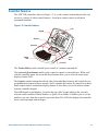
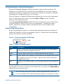
Controller Features
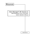
The ADTT16E controller, shown in Figure 1-2, is a video control station that provides easy
access to a variety of video control features—from basic camera control to advanced
automated functions.
Figure 1-2: Controller features
LCD
Keypad
A
B
Pe
el
Info
1
Me
O
Ou
tpu n
t
Off
nu
Zoom In
C le
4
5
Fli
p
6
7
Vie
w
Clo
se
8
Op
Zoom Out
D
3
ar
Iris
C
2
Pat
tern
9
en
Re
pea
t
Patt
er n
0
Se
q
Pre
vio
us
Nex
t
Tracker
Ball
Focus
Near
Focus Far
The Tracker Ball provides variable speed control of a camera's pan and tilt.
The zoom and focus buttons enable you to control a camera's zoom and focus. When used
with the controller menu, the zoom and focus buttons allow you to select the menu items
displayed on the LCD.
The keypad contains buttons that call up video from individual cameras and control the preprogrammed movement of those cameras. It also contains the buttons for camera iris control,
dome output control, and monitor display formats. It also allows you to clear dome alarms
from the controller keypad.
The LCD (liquid crystal display), located at the top of the keypad, displays the currently
selected camera number, Pattern Number, or Quick View number. It enables you to see the
numbers you enter from the keypad as you enter them. The LCD also displays the controller
menu, system prompts, and messages.
Getting Started with the ADTT16E Advanced Dome Controller
1-5
Controller Operating Modes
The ADTT16E controller functions differently depending upon the current operating mode.
Five operating modes are available:
•
•
•
•
•
Camera control mode
Menu/programming mode
Sequence mode
Alarm mode
Quest multiplexer control mode
Camera Control Mode
Camera control mode is the normal operating mode for the controller. In camera control
mode, the currently selected camera number and any running Pattern or Quick View appears
on the LCD. The Tracker Ball functions as the camera pan/tilt controller, and the zoom and
focus buttons control the zoom and focus of the currently selected camera. The following
tasks can be performed in camera control mode:
•
•
•
•
Change the display format for viewing video on the main monitor
Select individual cameras and display their video on the call monitor
Manually control cameras
Initiate automatic system functions
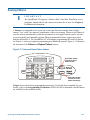
Menu/Programming Mode
Pressing the Menu button on the keypad activates menu/programming mode. In this mode,
the LCD displays the available menu items, and the Tracker Ball scrolls through the items.
There are always two menu items visible at one time on the LCD
The zoom and focus buttons are used to select the menu items. The zoom buttons (left of
Tracker Ball) selects the first line of the LCD. The focus buttons (right of Tracker Ball)
selects the second line of the LCD.
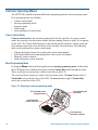
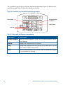
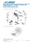
Figure 1-3: Operating in menu/programming mode
The LCD displays the
menu items.
A
The Tracker Ball scrolls
through the menu.
B
Pee
l
Info
1
Me
2
Off
C le
D
3
4
ar
5
Iris
Zoom selects the
first line of the LCD.
C
On
Out
put
nu
Flip
6
7
C lo
se
Vie
w
8
O pe
Patt
ern
9
n
Rep
eat
Patt
er n
0
Seq
Pre
viou
s
Next
Focus selects the
second line of the LCD.
1-6
ADTT16E Advanced Dome Controller Operator's Manual
Tip: The A, B, C, and D buttons may also be used in menu/programming
mode. The A or B buttons select menu items. C and D buttons scroll through
the menu.
•
•
•
•
A selects the first line on the LCD
B selects the second line item on the LCD
C scrolls to the previous menu item
D scrolls to the next menu item.
The following tasks can be performed in menu/programming mode:
• Configure system settings: external device, LCD display language, and Primary or
Secondary controller.
• Program automatic functions: Quick Views, Patterns, and Controller Sequence
• Program dome alarm actions: inputs triggering alarms with associated camera actions,
and output activated whenever an alarm is triggered.
• System maintenance functions: test device communications (ping), reset domes, display
version information, adjust LCD backlighting, and adjust key click sound.
Sequence Mode
Pressing the Seq button on the keypad activates the sequence mode. This runs the
Controller Sequence programmed using menu/programming mode. The Controller Sequence
consists 16 previously defined Quick Views and Patterns (called events). These events run
one after the other on the monitor. The sequence mode provides you with an unattended
surveillance of your facility. The Controller Sequence runs continuously until you stop it
manually.
When the controller is in the sequence mode, the LCD displays the following information:
• Camera number whose video appears on the monitor
• The event number (1 through 16) that the Sequence is currently displaying
• The remaining seconds that until the next event occurs
For more information about the Controller Sequence, see chapters 3 and 4.
Getting Started with the ADTT16E Advanced Dome Controller
1-7
Alarm Mode
The controller automatically goes into alarm mode whenever an alarm is triggered,
regardless of the operating mode. When the alarm mode is active, the controller beeps
intermittently until the alarm is cleared (either automatically or manually by pressing the
Clear button).
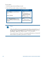
Alarms are configured using menu/programming mode. When configuring the alarm, you
determine what triggers the alarm and what actions occur in response to the alarm. The
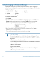
following illustration shows an example of the controller LCD during alarm mode.
Cam 3
Alarm2
Src:Cam 5 Inp3
In the previous example, there are currently two alarms active. The alarm whose information
appears on the LCD was triggered by input 3 of camera 5. The video from camera 3 appears
on the Main monitor.
For more information about alarms, see Chapters 3 and 4.
Quest Multiplexer Control Mode
If the controller is configured to interface with the Quest triplex multiplexer, many advanced
features of the multiplexer can be accessed. When the controller is Quest Multiplexer control
mode, the controller can be used to access the multiplexer display formats, digital zoom,
freeze frame, and sequence features. The following controls are used:
A
Displays the multiplexer sequence screens.
B
Toggles between multiplexer digital zoom and zoom area adjustment.
C
Toggles between freeze frame and freeze field mode.
D
Exits the current multiplexer mode.
Tracker
Ball
(Display)
Adjusts the position of highlighted window or zoom area.
Changes display format between the available multiplexer window
formats.
Assigns specific cameras to windows in multiplexer display format.
(Camera)
Zoom or
Focus
Selects the page to program for the selected multiplexer sequence.
For more information about the Quest triplex multiplexer functions, see Chapter 5.
1-8
ADTT16E Advanced Dome Controller Operator's Manual
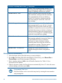
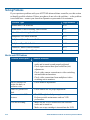
What To Do Next
Now that you have a basic understanding of the ADTT16E advanced dome controller, you
can begin using the system. The following table lists where to find additional information
about using the system features:
Chapter
Features Covered
Chapter 2:
Changing Configuration
Settings
•
•
•
•
Chapter 3:
Operating the ADTT16E
Advanced Dome
Controller
•
•
•
•
•
•
Chapter 4:
Programming System
Functions
•
•
•
•
Chapter 5:
Quest Multiplexer
Control
•
•
•
•
Changing the language setting
Configuring Primary and Secondary controllers
Configuring the external system
Setting the controller passwords
Logging on and off the controller
Selecting the display format for the monitor
Selecting and controlling cameras
Running Quick Views, Patterns, and the Sequence
Controlling dome outputs
Responding to alarms
Programming Quick Views
Programming Patterns
Programming the 16-event Controller Sequence
Programming actions for dome alarms
Accessing the Quest multiplexer sequences
Controlling multiplexer digital zoom
Switching between freeze frame and freeze field
modes
Programming multiplexer sequences
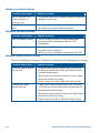
Chapter 6:
Using System Utilities
and Solving Problems
•
•
Accessing dome utilities
Accessing controller utilities
Troubleshooting system problems
Appendix A: Software
License Agreement
•
Terms and conditions for using the product
•
Getting Started with the ADTT16E Advanced Dome Controller
1-9
N O T E S :
1-10
ADTT16E Advanced Dome Controller Operator's Manual
CHAPTER 2
Changing Configuration Settings
Before performing other tasks, verify that your ADTT16E advanced dome controller
configuration settings are correct. Follow the instructions in this chapter to set the language,
configure primary or secondary controller settings, configure the external system, and enable
or disable passwords.
In This Chapter
•
•
•
•
Setting the Language for Prompts and Messages....................................................... 2-2
Setting Up Primary versus Secondary Controllers..................................................... 2-3
Configuring the External System ............................................................................... 2-5
Using Passwords to Restrict System Access.............................................................. 2-6
IMPORTANT
If passwords have been programmed for the controller, you must first log on
before performing the tasks in this chapter. See Chapter 3 for log on
instructions.
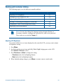
Setting the Language for Prompts and Messages
English is the initial setting for controller prompts and messages. Change the language
setting if you need to display the prompts and messages in another language. The following
languages are supported:
•
•
•
•
English (default)
French
Spanish
German
•
•
•
•
Dutch
Italian
Japanese
Portuguese
• Swedish
• Hungarian
To change the language setting:
1. Press Menu.
2. Scroll through the menu items until Select Language appears on the LCD. Press
Zoom to select the first line of the LCD, or press Focus to select the second line.
The list of supported languages appears on the LCD, two languages at a time.
English
Français
3. Scroll through the list until the preferred language setting appears. Press Zoom or
Focus to select the language setting.
The controller automatically restarts to activate the new setting.
IMPORTANT
Extra controller appliqués are available for each supported language. Contact
your American Dynamics representative for replacement appliqués. To replace
the appliqué:
1. Disconnect power from the controller.
2. Use a Philips-head screwdriver to remove the screws holding the controller's
top cover in place.
3. Remove the old appliqué.
4. Insert the new appliqué.
5. Replace the top cover. Insert the screws removed in step 2 and tighten.
6. Reconnect power to the controller.
2-2
ADTT16E Advanced Dome Controller Operator's Manual
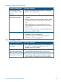
Setting Up Primary versus Secondary Controllers
If two controllers are installed, one must be configured as the Primary Controller, and one
must be configured as the Secondary Controller. The Primary Controller interfaces with the
multiplexer or other video switching unit. In addition, the Primary Controller can change the
display format of the Main Monitor and supports all system programming features.
The Secondary Controller controls the video information displayed on the Call monitor only
and provides limited programming functions.
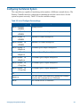
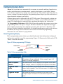
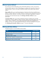
Table 2-1: Primary and Secondary Controllers supported functions.
Controller Functions
Primary
Controller
Secondary
Controller
Designate which external unit the system is
connected to (quad splitter, multiplexer, PC, no
unit)
Select display mode (2x2, 3x3, 4x4, or fullscreen format
Select a camera
Manually control a camera (pan, tilt, zoom,
focus, iris)
Flip a SpeedDome
Initiate automatic system functions (Quick
Views, Patterns, outputs)
Program and run the Sequence
Program and clear alarms
Define automatic system functions (Quick
Views, Patterns)
Reset a SpeedDome
Select language for Controller LCD text
Designate Primary vs. Secondary Controller
Adjust LCD brightness, speaker volume, and
turn key click on / off
Lock the multiplexer
9
*
9
9
9
9
9
9
9
9
9
9
9
9
*
*
9
9
9
9
9
9
9
9
9
9
*
* Menu options related to these items display on the secondary controller.
However, when attempting to select the controller beeps to indicate that the
function is not available.
If passwords are enabled, certain functions may not be available depending upon the
password level in currently use. See Using Passwords to Restrict System Access on page
2-6.
Changing Configuration Settings
2-3
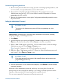
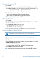
Changing the Primary/Secondary Controller Setting
IMPORTANT
If only one controller is installed, it must be configured as the Primary Unit.
1. Press Menu.
2. Scroll through the menu items until Tog Primary/2nd appears on the LCD.
Press Zoom or Focus to select.
Tip: Zoom selects the first line of the LCD; Focus selects the second line.
3. If configured as the Primary Controller, the LCD displays:
Primary Unit
Change w <Next>
If configured as the Secondary Controller, the LCD displays:
Secondary Unit
Change w <Next>
4. Press Next to change the controller setting. Each time Next is pressed, the display
toggles between Primary Unit and Secondary Unit.
A
C
B
D
Peel
1
Flip
3
View
Info
On
Output
Menu
Off
Clear
Close
Iris
4
5
6
7
8
9
0
Open
Pattern
Repeat
Pattern
Previous
Next
Press Next to switch between
Primary and Secondary Mode.
5. Press Menu to save the setting. If the setting changed, the controller restarts to activate
the new setting.
2-4
ADTT16E Advanced Dome Controller Operator's Manual
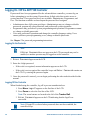
Configuring the External System
The controllers are capable of interfacing with a number of different external devices. The
Primary Controller must be configured to communicate with the correct device for the
system to operate correctly. Table 2-2 lists the available settings.
Table 2-2: List of Configure Device settings
Device Setting
Description
Device=Quad
=POSEM
Device=Mux 4
=POSEM
Device=Mux 9
=POSEM
Device=Mux 16
=POSEM
Device=Mux 4
=Duplex
Device=Mux 9
=Duplex
Device=Mux 16
=Duplex
Device=Mux 10
=Triplex
Device=Mux 16
=Triplex
Quad processor
PC
Reserved for service use.
Remote
Use this option if the controller is installed at a remote
location and communicates at 1200 baud.
None
No external device is connected.
Changing Configuration Settings
Standard 4-channel multiplexer
Standard 9-channel multiplexer
Standard 16-channel multiplexer
4-channel Quest Duplex multiplexer
9-channel Quest Duplex multiplexer
16-channel Quest Duplex multiplexer.
10-channel Quest Triplex multiplexer
16-channel Quest Triplex multiplexer.
2-5
Changing the External Device Setting
IMPORTANT
Only the Primary Controller can be used to perform this task.
1. Press Menu.
2. Scroll through the menu items until Config Devices appears on the LCD.
Press Zoom to select the first line of the LCD, or Focus to select the second line.
3. The LCD displays the current setting. Press Next to display the device types.
4. When the correct device appears on the top line of the LCD, press Menu to save the
device setting.
Using Passwords to Restrict System Access
When initially installed, the ADTT16E system provides full system programming authority
to anyone with access to the Primary Controller. This configuration is suitable if you are not
concerned about users changing system features, such as Quick Views, Patterns, or
Sequences. If this is the case, continue with programming other system features.
However, if you do not want all users to have the ability to program system features,
implement password protection. This allows you set three system access levels:
Administrator level, Programmer level, and User (Operator) level. In order to use the
system, the appropriate 4-digit code must be entered on the controller when the Enter
Password prompt appears on the LCD.
Note: Passwords are separate for each controller. If two controllers are
installed, you may choose to implement passwords on one controller but not the
other. If you forget the password, contact your American Dynamics
representative for instructions.
To implement password protection, program the Administrator password first. After the
Administrator password is set, program the Programmer and Operator passwords.
2-6
ADTT16E Advanced Dome Controller Operator's Manual
Password Programming Guidelines
1. Do not create passwords that can be easily guessed. Avoid using repeating numbers, such
as 1111 or 2222, or sequential numbers, such as 1234 or 9876.
2. Passwords for each privilege level should be distinct. For example, if you set the
Administrator password to be 6528, you would not want the Programmer or Operator
passwords to be 6527 or 6529.
3. Keep the list of passwords in a secure place. Only permit authorized personnel to access
the password list.
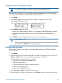
Setting the Administrator Password
IMPORTANT
You must set the administrator password before programming any other
password.
Administrators are authorized to perform all tasks documented in this book, including
assigning, changing, or disabling passwords.
1. Press Menu.
2. Scroll through the menu items until Admin Password appears on the LCD. Press
Zoom to select the first line of the LCD or Focus to select the second line.
3. Enter New Pswd appears on the LCD. Use the number buttons to enter the 4-digit
Administrator password. Press Zoom or Focus to save.
Note: Asterisks (*) appear on the LCD as the numbers are entered.
4. ReEnter New Pswd appears on the LCD. Enter the 4-digit Administrator password
used in step 3. Press Zoom or Focus to save.
IMPORTANT
If the same password is not entered, the controller beeps, and you must start
programming again at step 3.
5. Once the password is set, the controller menu displays. Press Menu to return to normal
controller operation.
Make note of the Administrator password, and keep it in a secure place. Provide this
password only to users requiring the authority to set, change, or disable passwords on the
controller. A password must be entered anytime the controller is used.
You can now program the Programmer and Operator passwords.
Changing Configuration Settings
2-7
Setting the Programmer Password
Once the Administrator password is set, assign Programmer and User (Operator) passwords.
Programmers can perform all programming tasks documented in this book except setting,
changing, or disabling passwords.
IMPORTANT
You must be logged on as the Administrator to set the Programmer password.
1. Press Menu.
2. Scroll through the menu items until Program Password appears on the LCD. Press
Zoom to select the first line of the LCD or Focus to select the second line.
3. Enter New Pswd appears on the LCD. Use the number buttons to enter the 4-digit
Programmer password. Press Zoom or Focus to save.
Note: Asterisks (*) appear on the LCD as the numbers are entered.
4. ReEnter New Pswd appears on the LCD. Enter the 4-digit Programmer password
used in step 3. Press Zoom or Focus to save.
IMPORTANT
If the same password is not entered, the controller beeps, and you must start again
at step 3.
5. Once the password is set, the controller menu displays. Press Menu to return to normal
controller operation.
Make note of the Programmer password and keep it in a secure place. Provide this password
to those users who require the authority to program system features, such as Quick Views,
Patterns, and sequences. A password must be entered anytime the controller is used.
2-8
ADTT16E Advanced Dome Controller Operator's Manual
Setting the User Password
Users (operators) are restricted from performing any programming tasks. Users can only
operate the ADTT16E system, log on or log off the controller, and change the LCD language
setting.
IMPORTANT
You must be logged on as the Administrator to set the User (Operator) password.
1. Press Menu.
2. Scroll through the menu items until User Password appears on the LCD. Press
Zoom to select the first line of the LCD or Focus to select the second line.
3. Enter New Pswd appears on the LCD. Use the number buttons to enter the 4-digit
User password. Press Zoom or Focus to save.
Note: Asterisks (*) appear on the LCD as the numbers are entered.
4. ReEnter New Pswd appears on the LCD. Enter the 4-digit User password used in
step 3. Press Zoom or Focus to save.
IMPORTANT
If the same password is not entered, the controller beeps, and you must start again
at step 3.
5. Once the password is set, the controller menu displays. Press Menu to return to normal
controller operation.
Make note of the User password and keep it in a secure place. Provide this password to those
users who require the authority to perform basic system operations. A password must be
entered anytime the controller is used.
Changing Configuration Settings
2-9
Disabling Passwords
Disable passwords by setting the Administrator password to “0000” (four zeros). Perform
this task on each controller where passwords have been set.
1. Enter the current Administrator password at the Enter Password prompt on the
controller.
2. Press Menu.
3. Scroll through the menu items until Admin Password appears on the LCD.
Press Zoom to select the first line of the LCD or Focus to select the second line.
4. Enter New Pswd appears on the LCD. Use the number buttons to enter 0000.
Press Zoom or Focus to save.
Note: Asterisks (*) appear on the LCD as the numbers are entered.
5. ReEnter New Pswd appears on the LCD. Enter the 0000 again. Press Zoom or
Focus to save.
IMPORTANT
If the same password is not entered, the controller beeps. You must start again at
step 4.
6. Press Menu to return to normal controller operation.
Once the Administrator password is set to 0000, all passwords are disabled. A password is
no longer required to use the controller.
Tip: If you experience problems disabling the password, program all password
levels first, and then follow the procedure for password removal.
2-10
ADTT16E Advanced Dome Controller Operator's Manual
CHAPTER 3
Operating the ADTT16E Advanced Dome Controller
This chapter explains how to operate the ADTT16E advanced dome controller. It explains
how to log on and off the controller if passwords are enabled. It describes how to change the
monitor display format, select and control cameras, run automated system functions, and
how to activate flip and peel functions for SpeedDome series camera domes. In addition, it
explains how to control dome outputs and clear system alarms.
In This Chapter
•
•
•
•
•
•
•
•
•
Logging On / Off the ADTT16E Controller .............................................................. 3-2
Monitor Display Formats ........................................................................................... 3-3
Selecting and Controlling Cameras............................................................................ 3-6
SpeedDome Peel and Flip Features.......................................................................... 3-11
Displaying Quick Views .......................................................................................... 3-12
Running Patterns ...................................................................................................... 3-13
Running the Controller Sequence ............................................................................ 3-15
Controlling Dome Outputs ....................................................................................... 3-16
Clearing System Alarms........................................................................................... 3-17
Logging On / Off the ADTT16E Controller
If passwords have been programmed for the advanced dome controller, you must log on
before attempting to use the system. Passwords are 4-digit codes that restrict access to
system functions. Three password levels are available: Administrator, Programmer, and
User. The functions available are based upon the password level assigned.
•
•
•
Administrators have full system privileges. Administrators may set, change or disable
passwords, program all system functions, and perform all system operations.
Programmers may perform all system programming and operations. Programmers cannot
set, change or disable passwords.
Users may perform all operations and change the controller language setting. Users
cannot perform system programming or set, change or disable passwords.
See Chapter 2 for password programming instructions.
Logging On the Controller
Note
If Enter Password does not appear on the LCD, passwords may not be
enabled, or another operator may be logged on to the controller.
1. Enter Password appears on the LCD.
2. Enter the 4-digit password.
•
If the code is recognized, camera information appears on the LCD.
•
If the code is not recognized the controller beeps and Enter Password remains on
the LCD. Try entering the password again.
3. Once the password is entered, you can begin performing the other tasks described in this
manual.
Logging Off the Controller
When finished using the controller, log off to prevent unauthorized use.
1. Press Menu. Logoff appears on the first line of the LCD.
2. Press Zoom to select the first line of the LCD.
Note: The zoom buttons are located to the left of the Tracker Ball.
3. Enter Password appears on the LCD indicating that the logoff was
successful.
Note: If Logoff is selected when passwords have not been enabled, the
controller beeps.
3-2
ADTT16E Advanced Dome Controller Operator's Manual
Monitor Display Formats
Tip: Only the Primary Controller can be used to perform this task.
Depending upon the installed switching device, video may be displayed in 2X2 (4 cameras),
3X3 (9 cameras), or 4X4 (16 cameras) format. Video from the selected camera may also be
displayed in full-screen format.
Note
If a Multivision Quest multiplexer is installed, other display formats are
available. Refer to Chapter 5 for more information.
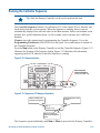
Pressing
(Display button) on the Primary Controller switches between the available
display formats. This button serves no function on the Secondary Controller. Figure 3-1
illustrates the location of the Display button.
Figure 3-1: Display button
A
C
B
D
Peel
1
Flip
3
View
Info
4
On
Output
Menu
Off
7
Clear
Close
Iris
Open
5
8
0
6
Pattern
Repeat
Pattern
9
Previous
Next
Press to change
display formats.
Operating the ADTT16E Advanced Dome Controller
3-3
Displaying Video with Quad Processors
Quad processors provide the ability to see video from up to eight cameras. The video can be
viewed from each camera individually, or it can be displayed in quad mode.
QUAD DISPLAY MODE
Quad display mode allows video from 4 cameras to
be displayed at once on the monitor. The camera
number appears in the bottom of its respective
quadrant on the monitor.
Depending upon the model, as many as eight cameras may be connected to your system.
However, only video from four cameras can be displayed at one time. If a dual page quad
processor is being used, the camera display is divided into two “pages.” Page 1 displays
Cameras 1 through 4; page 2 displays cameras 5 through 8.
To switch back and forth between pages, press
(Display button) on the Primary
Controller. By pressing
, the monitor display changes from page 1, to page 2, to fullscreen display. Regardless of which display format is active, you will always have control
over the camera indicated on the controller LCD.
(Display button) to
Tip: If your system includes only one monitor, press
put the monitor in the quad display format. Press the number associated with an
individual camera to call that camera to the full-screen mode (or select the fullscreen display mode via the Display button).
If your system includes two monitors, the Main monitor is dedicated to quad
display, and the Call monitor is dedicated to full-screen display.
Displaying Video with Multiplexers
Multiplexers allow viewing of up to 16 cameras simultaneously. Cameras may be called up
individually or the cameras may be displayed in one of the multiplexed modes. Three types
of multiplexers are available. Triplex multiplexers allow simultaneous viewing of live video
and playing back recorded video while recording video from up to 16 cameras. Duplex
multiplexers allow viewing live video or playing back recorded video while also recording
video from up to 16 cameras. Simplex multiplexers allow viewing cameras full-screen mode
while recording of up to 16 cameras or displaying the cameras in a multiplexed mode when
recording is off.
Standard simplex and duplex multiplexers are available in 4-camera, 9-camera, and 16camera models. When cameras are displayed in the multiplexed mode, they can be displayed
in 2x2, 3x3, or 4x4 format, depending upon the installed multiplexer. See Chapter 5 for
information about Quest multiplexers and the display formats available.
3-4
ADTT16E Advanced Dome Controller Operator's Manual
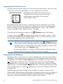
2x2 DISPLAY FORMAT
Video displays from 4 cameras when 2x2 format is
active. 4-, 9-, and 16-camera multiplexers support this
display format.
3x3 DISPLAY FORMAT
Video displays from 9 cameras when 3x3 format is
active. 9- and 16-camera multiplexers support this
display format.
1
2
3
4
5
6
7
8
9
4x4 DISPLAY FORMAT
1
5
Press
2
6
3
7
4
8
9
10 11 12
13
14 15 16
Video displays from 16 cameras when 4x4 format is
active. 16-camera multiplexers support this display
format.
(Display button) on the Primary Controller to choose from the available display
formats. Each time you press
, the monitor changes from 2x2, 3x3, 4x4, or full-screen
format. Regardless of which display format is active, you will always have control over the
camera indicated on the controller LCD.
(the Display button)
Tip: If the system includes only one monitor, press
to put the monitor in the multi-camera display format. Press the number
associated with an individual camera to call that camera to the full-screen mode
(or select the full-screen display mode by pressing
).
If your system includes two monitors, the Main monitor is dedicated to multicamera display and the Call monitor is dedicated to full-screen display.
If your system includes one controller with two monitors, the controller may be
used to control either Main or the Call monitor. To switch control to the Call
monitor, press the Sel button on the multiplexer twice. To return control to the
Main monitor, press the Sel button again.
Operating the ADTT16E Advanced Dome Controller
3-5
Selecting and Controlling Cameras
Each camera has been assigned a unique number. To select a camera, enter the camera
number and press
button.
(Camera button). Figure 3-2 illustrates the location of the Camera
Figure 3-2: Camera button
A
C
B
D
Peel
1
3
Flip
6
Pattern
View
Info
4
On
Output
Menu
Off
7
Clear
Close
Iris
Open
5
8
Repeat
Pattern
9
0
Previous
Next
Enter a camera
number and press
to select a camera.
Full-screen video from the selected camera appears on the monitor. The associated camera
number appears in the bottom left corner of the monitor. If the camera is selected via the
Primary Controller, video appears on the Main monitor. If the camera is selected via the
Secondary Controller, video appears on the Call monitor.
How the System Resolves Conflicts in Camera Control
If the configuration includes two controllers, the Primary Controller will always have camera
control priority over the Secondary Controller. The Primary Controller “locks” the selected
camera, and the Secondary Controller will only be able to display its video on the Call
monitor. The following situations may occur:
3-6
Situation
Message on Secondary Controller
The Secondary Controller attempts to
control a camera that is currently selected
by the Primary Controller.
Camera In Use
The Primary Controller selects a camera
currently controlled by the Secondary
Controller. The Primary Controller secures
control of the camera.
Camera Override
ADTT16E Advanced Dome Controller Operator's Manual
The Primary Controller operator maintains control over the camera until one of the following
events occurs:
•
•
•
•
•
A different camera is selected
Menu/programming mode is started
The Controller Sequence is initiated
An alarm comes into the system
The selected camera remains idle for 3 minutes
Once the Primary Controller operator relinquishes control of a camera, the message,
Camera Free appears on the Secondary Controller (if the Call operator has that camera
selected).
Stepping Through the Cameras
Press the Previous and Next buttons to step backward and forward through all of the
cameras configured for your system. The video displays full-screen on the Main or Call
monitor depending upon the controller currently being used. Figure 3-3 illustrates the
locations of the Previous and Next buttons.
Figure 3-3: Previous and Next buttons
A
C
B
D
Peel
1
Flip
3
View
Info
4
On
Output
Menu
Off
7
Clear
Close
Iris
Open
Press to display previous
camera in series.
5
8
0
6
Pattern
Repeat
Pattern
9
Previous
Next
Press to display next
camera in series.
Note: Previous and Next step through the first 16 cameras. If more than 16
cameras are installed, the camera number must be manually entered.
Operating the ADTT16E Advanced Dome Controller
3-7
Controlling a Camera's Pan and Tilt
Camera movement can be manually controlled once a camera is selected. Pan is the
side-to-side camera movement. Tilt is the up and down camera movement.
The Tracker Ball controls the pan and tilt movements. Move the Tracker Ball left and
right to pan the camera. Move the Tracker Ball towards you or away from you to tilt the
camera. Figure 3-4 illustrates how to control the pan and tilt movements.
Figure 3-4: Pan and tilt movement using the Tracker Ball
Tilt Up
Pan Left
Pan Right
Tracker Ball
Tilt Down
You can simultaneously pan and tilt the camera for diagonal movement. Moving the
Tracker Ball diagonally up and to the right moves the pointing direction of the camera up
and to the right. Figure 3-5 illustrates diagonal camera movement.
Figure 3-5: Diagonal camera movement using the Tracker Ball
Moves camera
up to left.
Moves camera
down to left.
Moves camera
up to right.
Moves camera
down to right.
Camera movement speed is directly proportional to the distance the Tracker Ball moves
from its center position. For example if the Tracker Ball moves slightly to the right, the
camera pans slowly to the right. As the Tracker Ball moves farther to the right, the panning
speed increases until maximum speed is reached.
Note: This variable speed operation applies to programmable domes only.
Non-programmable domes provide two speeds: normal and fast.
3-8
ADTT16E Advanced Dome Controller Operator's Manual
Controlling Zoom and Focus
Control the zoom and focus settings of the selected camera by pressing the Zoom and
Focus buttons. Figure 3-6 illustrates the locations of these buttons.
Figure 3-6: Zoom and Focus buttons
Zoom In
Zoom Out
Focus Near
Focus Far
Zoom refers to adjusting the magnification of the camera lens to make an object appear
closer (larger) or more distant (smaller). To make objects appear closer to the camera, press
Zoom In. To make objects appear more distant from the camera, press Zoom Out. Quickly
pressing and releasing a zoom button displays only a slight visible change on the monitor.
The longer a zoom button is pressed, the more noticeable is the response.
Focus refers to the process of adjusting the clarity of a scene or an object, as seen through
the camera lens. To adjust the focus setting for the object or scene displayed, press a focus
button. Press Focus Near if the object is closer than the current focus setting. Press
Focus Far if the object is more distant than the current focus setting. The scene on the
monitor becomes either sharper and clearer or fuzzier and less clear. Like the zoom buttons,
the focus buttons react based on the length of time the button is pressed; the longer a focus
button is pressed, the more noticeable is the response.
Operating the ADTT16E Advanced Dome Controller
3-9
Controlling the Iris
Normally the camera's automatic gain function and the auto/manual iris function control the
brightness of the image. However, there may be times when the scene on the monitor could
be even darker or brighter. The iris control buttons—Iris Close and Iris Open—regulate
the image brightness. Figure 3-7 illustrates the location of the iris control buttons.
Figure 3-7: Iris control buttons
A
C
B
D
Peel
1
3
Flip
6
Pattern
View
Info
4
On
Output
Menu
Off
Close
Press to make the
image darker.
7
Clear
Iris
Open
5
8
Repeat
Pattern
9
0
Previous
Next
Press to make the
image brighter.
Press both iris control buttons simultaneously to
return to auto iris / auto focus operation.
Press Iris Close to make the picture darker. Press Iris Open to make the picture brighter.
To return to auto iris/auto focus mode, press both iris control buttons simultaneously.
3-10
ADTT16E Advanced Dome Controller Operator's Manual
SpeedDome Peel and Flip Features
The SpeedDome series camera domes support two special features called Apple Peel and
Flip. Pressing the appropriate buttons on the controller automatically activate these features.
Figure 3-8 illustrates the location of the Peel and Flip buttons.
Figure 3-8: Peel and Flip buttons
A
C
B
D
Peel
1
3
Flip
Pattern
View
Info
On
Press to run the
default SpeedDome
pattern.
Output
Menu
Off
Clear
Close
Iris
Open
4
5
6
7
8
9
0
Repeat
Pattern
Previous
Press to rotate the
SpeedDome 180°
Next
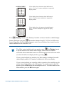
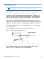
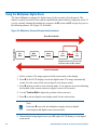
Running the “Apple Peel” Pattern
The Apple Peel pattern consists of three revolutions of camera panning (with tilt) starting at
the ceiling line. Each revolution tilts down approximately 30°. The Apple Peel pattern
provides you with a complete view of the area. Figure 3-9 illustrates the Apple Peel pattern
movement.
Figure 3-9: Apple Peel Pattern
Select the camera and press Peel to run the Apple Peel pattern. The Apple Peel pattern
repeats indefinitely until a camera command (pan, tilt, zoom, focus, or iris) is issued to the
camera. The following message displays on the LCD while the Apple Peel pattern is
running:
Cam 16
+
Apple Peel Patn
Note: If the ADTT16E controller is used with a Sensornet-to-RS-422 Code
Converter and Pattern 3 has been programmed, pressing Peel runs Pattern 3.
Operating the ADTT16E Advanced Dome Controller
3-11
“Flipping” the SpeedDome
A SpeedDome camera dome can rotate 180° from its current pointing direction by pressing
the Flip button. This feature is useful when tracking someone who walks directly under the
SpeedDome and continues walking on the other side. The message Flip Dome appears on
the second line of the LCD when the Flip button is pressed.
Cam 16
Flip Dome
+
Displaying Quick Views
Use Quick Views to call up specific scenes from programmable domes, regardless of the
current pointing direction. This feature is useful when you want to look at a particular item
or area quickly without manually adjusting pan, tilt and zoom. Depending on the dome type,
either 4 or 96 Quick Views may be defined for the selected dome. Figure 3-10 illustrates the
location of the View button.
Figure 3-10: View button
A
C
B
D
Peel
1
Flip
3
View
Info
4
On
Output
Menu
Off
7
Clear
Close
Iris
Open
5
8
0
6
Pattern
Repeat
Pattern
9
Previous
Enter Quick View number
and press to display the
Quick View.
Next
Chapter 4 provides Quick View programming instructions. If a list has been compiled for
your facility, refer to the Programming Worksheets (8200-0306-04) to determine which
Quick Views are available.
To display a Quick View:
1. Select the camera where the Quick View is saved.
2. Enter the Quick View number (1-96) and press View.
The camera immediately points to the programmed position, and then adjusts the zoom
and focus. The Quick View information appears on the second line of the LCD.
Cam 1
View 96
+
Note: The controller beeps if an invalid Quick View number is entered.
3-12
ADTT16E Advanced Dome Controller Operator's Manual
Running Patterns
IMPORTANT
The SpeedDome LT supports a feature called “Auto Pan” that allows you to
program a smooth side-to-side camera movement for an area. See Chapter 4
for additional information.
A Pattern is a sequential series of pan, tilt, zoom, and focus movements from a single
camera. You “teach” the camera a combination of these movements. Whenever the Pattern is
run, the camera automatically recalls the movements it was taught. Patterns can be run once
or run repeatedly until manually stopped. Most programmable domes support up to three
Patterns defined for it. The SpeedDome LT will support programming the Auto Pan feature
for Pattern 1; it does not support programming any additional patterns. Figure 3-11 illustrates
the locations of the Pattern and Repeat Pattern buttons.
Figure 3-11: Pattern and Repeat Pattern buttons
A
C
B
D
Peel
1
3
Flip
6
Pattern
View
Info
4
On
Output
Menu
Off
7
Clear
Close
Enter Pattern number
and press to run the
Pattern one time.
Iris
Open
5
8
0
Repeat
Pattern
9
Previous
Next
Enter Pattern number
and press to run the
Pattern continuously.
Chapter 4 provides Pattern programming instructions. If a list has been compiled for your
facility, refer to the Programming Worksheets (8200-0306-04) to determine which Patterns
are available for the installed domes.
Operating the ADTT16E Advanced Dome Controller
3-13
To run a pattern:
1. Select the camera where the Pattern is saved.
2. Enter the Pattern number, and press a pattern button.
Action
LCD Information
Press Pattern to run the Pattern
once.
Cam 8
Run Pattern
+
Pattern finished.
Cam 8
Pattern Done
+
Press Repeat Pattern runs the
Pattern indefinitely until manually
stopped.
Cam 8
+
Repeat Pattern
Notes
If the selected Pattern has been programmed, the Pattern automatically runs. If
the Pattern has not been programmed, the default Apple Peel pattern runs. See
Running the “Apple Peel” Pattern on page 3-11 for a description.
The controller beeps if a Pattern for a non-programmable dome or if an invalid
Pattern number (any number greater than 3) is entered.
3-14
ADTT16E Advanced Dome Controller Operator's Manual
Running the Controller Sequence
Tip: Only the Primary Controller can be used to perform this task.
The Controller Sequence consists of a collection of 16 events (Quick Views, Patterns, and
fixed shots) from the system cameras. When the Sequence is running, these events are
automatically displayed one after the other on the Main monitor. Each event remains on the
monitor for a specified duration (from 1 to 90 seconds); each event may have a different
duration.
Chapter 4 provides instructions for programming the Controller Sequence. Use to the
Programming Worksheets (8200-0306-04) to list Quick Views and Patterns to include in
the Controller Sequence.
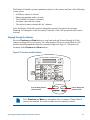
Press the Seq button on the Primary Controller to run the Controller Sequence. Figure 3-12
illustrates the location of the Sequence button. Figure 3-13 illustrates the information
appearing on the LCD when the Controller Sequence is running.
Figure 3-12: Sequence button
A
C
B
D
Peel
1
Flip
3
View
Info
On
Output
Menu
Off
Clear
Close
Press to start the
Controller Sequence.
(Primary Controller only)
Iris
Open
4
5
6
7
8
9
0
Pattern
Repeat
Pattern
Previous
Next
Figure 3-13: Sequence LCD display information
Current Sequence event
number
Camera number of the
currently running event
Cam 3
Sequencing
6
12
Seconds remaining
until the next Sequence
event
The Sequence repeats indefinitely until Seq or Clear is pressed on the Primary Controller.
Operating the ADTT16E Advanced Dome Controller
3-15
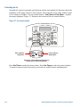
Controlling Dome Outputs
Output devices are hardware components connected to dome outputs that can be operated by
the controller. Typical output devices include gates, door strikes, and lights. Depending upon
the dome type, as many as four output devices may be connected. The output control
buttons on the controller activate or deactivate the output devices connected to the
currently selected dome. Figure 3-14 illustrates the location of these buttons.
Figure 3-14: Output control buttons
Press to activate the
selected dome
output.
A
C
B
D
Peel
1
Flip
3
View
Info
On
Output
Menu
Off
Clear
Close
Press to deactivate
the selected dome
output.
Iris
Open
4
5
6
7
8
9
0
Pattern
Repeat
Pattern
Previous
Next
The following procedure describes how to activate or deactivate a dome output. You must
know the dome number and the output number before performing this procedure.
1. Select the camera whose output state you want to control.
2. Enter the output number, and press an output control button.
Action
LCD Information
Press Output On to activate
Cam 13
Output On
+
Press Output Off to deactivate
Cam 13
Output Off
+
The controller beeps if an invalid output number or non-existent output number is
entered.
Tip: Up to 64 output devices can be configured at a single facility. Post a copy
of the Inputs / Outputs Worksheet found in the Programming Worksheets
(8200-0306-04) next to the controllers to help operators determine which
outputs are available.
3-16
ADTT16E Advanced Dome Controller Operator's Manual
Clearing System Alarms
Tip: Only the Primary Controller can be used to perform this task.
The ADTT16E advanced dome controller can be configured to handle up to 64 alarms.
When an alarm is triggered, it takes precedence over the activity currently being performed
on the Main monitor and Primary Controller. For example, if the controller is in
programming mode, the alarm information replaces the programming information. If the
Controller Sequence is running, the alarm information replaces the sequence information,
and alarm video replaces the sequence video on the Main monitor. The Call monitor and
Secondary Controller remain unaffected by incoming alarms.
Each alarm can be configured to automatically call up video and initiate an output. For
example, when an alarm is triggered, it can automatically run a specific Pattern and set off an
audible alarm. In addition, whenever an alarm is triggered, the controller beeps, signaling an
active alarm. The controller continues to beep intermittently until the alarm is cleared.
Only four alarms may be active at once. If a fifth alarm becomes active, the oldest alarm is
removed from the queue.
The following illustrates an example of the LCD when two alarms are active.
Figure 3-15: Alarm information appearing on the LCD
Number of active alarms
Camera displaying alarm
video
Cam 3
Alarm2
Src: Cam 5
Inp3
Camera and input triggering
the alarm
The default system setting automatically clears alarms after 60 seconds. No action is required
by the operator to clear alarms as long as automatic alarm acknowledgment is enabled.
However, alarms can manually cleared by pressing the Clear button on the Primary
Controller. Figure 3-16 illustrates the location of the Clear button.
Operating the ADTT16E Advanced Dome Controller
3-17
Figure 3-16: Clear button
A
C
B
D
Peel
1
Flip
3
View
Info
4
On
Output
Menu
Off
7
Clear
Close
Iris
Open
5
8
0
6
Pattern
Repeat
Pattern
9
Previous
Next
When you clear an alarm, its associated output returns to its original state, and the alarm
information is removed from the LCD. Continue to press Clear until all active alarms have
been acknowledged.
The controller stops beeping after all active alarms are cleared. If the Controller Sequence
was running the before the alarm occurred, the sequence restarts from the beginning. If
system programming was in process when the alarm occurred, you resume programming
from the beginning.
3-18
ADTT16E Advanced Dome Controller Operator's Manual
CHAPTER 4
Programming Controller Functions
This chapter explains how to program the automatic functions for the ADTT16E advanced
dome controller. Programming instructions for Quick Views, Patterns, and the Controller
Sequence are provided. In addition, system alarm set up is explained.
In This Chapter
•
•
•
•
•
Programming Quick Views.................................................................................................... 4-2
Programming Patterns............................................................................................................ 4-3
Programming the Controller Sequence.................................................................................. 4-5
Configuring System Alarms .................................................................................................. 4-8
SpeedDome LT Auto Pan Programming ............................................................................. 4-11
Programming Quick Views
A Quick View is a programmed video scene based on specific pan, tilt, zoom, and focus
settings for a programmable dome. Program Quick Views if you need to frequently observe
specific locations, such as entrances, lobbies, or loading docks. Presets and Targets are other
names used for Quick Views.
When accessed, the Quick View automatically calls up the scene for the selected dome,
regardless of where the dome is currently pointing. Either four or 96 Quick Views may be
programmed, depending on the programmable dome type.
Quick View Programming Instructions
1. Select the camera where the Quick View will be saved.
2. Adjust the pan, tilt, zoom and focus settings for the camera until the scene you want to
save appears on the monitor.
3. Press Menu.
4. Scroll through the menu until Setup View is displayed on the LCD. Press Zoom or
Focus to select.
Tip: Zoom selects the first line; Focus selects the second line.
5. Enter View#? appears on the LCD. Enter the view number (1-96), then press Zoom,
Focus or View to save. View Saved appears briefly on the LCD.
Note: The controller beeps if an invalid Quick Viewer number is entered. If this happens,
enter a valid number, and the Quick View will be saved.
The controller automatically returns to the camera control mode after saving the Quick
View. Make a record of the Quick View, including the camera number and a brief
description in the Programming Worksheets (8200-0306-04).
Programming Time Saver
To quickly program a Quick View, first adjust the camera to the desired scene.
Press Menu, and then press View. You will be prompted to assign a View
number. Enter the Quick View number (1-96), and press Zoom, Focus, or
View to save.
4-2
ADTT16E Advanced Dome Controller Operator's Manual
Programming Patterns
A Pattern is a series of pan, tilt, zoom and focus movements from a single programmable
dome. Program Patterns if you need to observe large areas at your facility, such as parking
lots, warehouses, or long hallways. Tour is another name used for Pattern. Depending on
dome type, up to three patterns may be programmed.
IMPORTANT
If you have SpeedDome LT domes installed, a special pattern called the Auto
Pan is available. The Auto Pan is a smooth side-to-side motion that can be
programmed for Pattern 1. No other patterns may be programmed for the
SpeedDome LT. See SpeedDome LT Auto Pan Programming on page 4-11 for
more information.
Pattern Programming Limitations
Two variables restrict pattern length and complexity:
•
•
Number of available camera commands
Time
Camera commands are issued each time the camera moves or the zoom and focus is adjusted.
The three Patterns for a dome can collectively use 98 camera commands. As you program a
Pattern, the number of remaining camera commands appears on the LCD. Depending on the
dome type, the number of available commands may also be displayed on the monitor.
Patterns also have time constraints. The maximum duration for each Pattern is 6 minutes and
50 seconds. Even if the Pattern has only two camera commands in it, the Pattern will stop
recording once the maximum duration has elapsed.
Patterns are programmed in real-time. This means that the camera is recording every
programming command made at the speed the commands are issued. For example, if the
camera sits motionless for 20 seconds during programming, the camera pauses for 20
seconds each time that Pattern runs. The 20 seconds of motionless time is part of the Pattern.
Tip: If you make a mistake during programming or you no longer want to
program the Pattern, press the Menu or the Clear button at any time to cancel
programming. The controller returns to the camera control mode.
Programming Controller Functions
4-3
Pattern Programming Instructions
1. Select the camera for the Pattern you want to program.
2. Adjust the pan, tilt, zoom and focus settings for the camera until the starting point for the
Pattern appears on the monitor.
3. Press Menu.
4. Scroll through the menu until Record Pattern appears on the LCD. Press Zoom or
Focus to select.
5. Enter Patrn#? appears on the LCD. Enter the Pattern number (1-3).
The following information appears on the LCD:
Record Pattern 98
Finish w <Next>
Available commands
6. Move the camera around and create the Pattern. The LCD displays the number of
remaining commands while the Pattern in programmed.
7. Press Next when finished programming. Pattern Saved appears briefly on the LCD.
The controller automatically returns to camera control mode after saving the Pattern. Make a
record of the Pattern, including the camera number and a brief description in the
Programming Worksheets (8200-0306-04).
Programming Time Saver
To quickly program a Pattern, first adjust the camera to the starting point of the
Pattern. Press Menu, and then press Pattern. Enter the Pattern number (1-3) to
start programming. Move the camera in the desired pattern. When finished
programming, press Next to save the Pattern.
4-4
ADTT16E Advanced Dome Controller Operator's Manual
Programming the Controller Sequence
Program the Controller Sequence if different locations require regular monitoring. The
Sequence is of a collection of 16 events that have been defined for your system's cameras
initiated by the Primary Controller. Each event can be a Quick View, Pattern, or fixed shot
that displays for a designated period (1 to 90 seconds).
When the Sequence is running, the Main monitor displays these events in the programmed
order. If suspicious activity is observed, pressing Seq or Clear stops the Controller
Sequence on the displayed camera.
Use the Programming Worksheets (8200-0306-04) to identify the events to include in the
Controller Sequence. List all of the events to be programmed —including the camera
number, Quick View or Pattern number, and duration. Refer to this worksheet while
programming.
Sequence Programming Display
Before programming the sequence, you should understand what information is displayed,
and how the controller is used for programming. Figure 4-1 illustrates the fields appearing
on the LCD; Table 4-1 describes the fields.
Figure 4-1: Sequence programming LCD display.
Evt Cam Act
Dur
01
- - View-- --
Cursor
Table 4-1: Sequence programming fields
Field
Description
Evt
Event: 16 slots used to run the actions in the sequence. The event number
determines when the assigned action runs.
Cam
Camera number: Any of the 16 cameras installed with the system.
Act
Action: Quick Views, Patterns, or Fixed Shots for the cameras that run when
the assigned event occurs. If View-- appears in the field, a Fixed Shot is
assigned to the event.
Duration: The amount of time (1 to 90 seconds) that the event is assigned to
run.
The blinking square on the LCD represents the cursor's location. Move the Tracker Ball
left and right to move the cursor between the fields for the event. Move the Tracker Ball up
and down to move between events.
Dur
Note: When the fields in an event have dashes in them instead of values, the
event is not defined. The Controller Sequence skips the event whenever it runs.
Programming Controller Functions
4-5
The controller keypad is also used during sequence programming. Figure 4-2 illustrates the
controller keypad; Table 4-2 describes which keys are used.
Figure 4-2: Controller keys used with Sequence programming
Enter numbers
A
C
B
D
Peel
1
3
Flip
6
Pattern
View
Info
4
On
Output
Clear field
Menu
Off
7
Clear
Close
Assign Quick View
or fixed shot
Iris
Open
5
8
0
Assign Pattern
Repeat
Pattern
9
Previous
Next
Table 4-2: Keys used with Sequence programming
4-6
Keys Used
Description
Numeric keypad
Enters the camera numbers, Quick View or Pattern numbers, and the
event duration.
Pattern
Changes the assigned action to a pattern.
View
Changes the assigned action to a Quick View or fixed shot. Leave the
View number blank for fixed shots.
Clear
Erases the information for the selected field. This allows the event to
be reprogrammed or skipped.
ADTT16E Advanced Dome Controller Operator's Manual
Sequence Programming Instructions
1. Press Menu.
2. Scroll through the menu until Define Sequence appears on the LCD. Press Zoom
or Focus to select. Information for the first event displays on the LCD. Continue with
step 4 to program this event. Otherwise, continue with step 3.
3. Move the Tracker Ball up or down to scroll to the event you want to define. If
necessary, press Clear to remove any previously programmed information.
4. Enter the camera number in the Cam field.
5. Move the cursor right to the Act field. Do one of the following:
•
Press View and enter the view number (1-96) to display a Quick View.
•
Press View and leave the number field blank to display a fixed shot.
•
Press Pattern and enter the pattern number (1-3) to run a Pattern.
6. Move the cursor right to the Dur field. Enter the event duration time (1 to 90 seconds).
7. Repeat steps 3 through 6 to program more events. When you complete defining the
Sequence, press the Menu button. This returns the controller to the camera control mode.
Programming Time Saver
To quickly start Controller Sequence programming, press Menu, and then press
Seq. Follow steps 3 through 7.
Programming Controller Functions
4-7
Configuring System Alarms
Alarms are events that occur automatically in response to external conditions. Input devices,
such as smoke detectors or motion sensors, connect to the domes at your facility. Alarms
occur whenever input devices change to its abnormal state. This situation places the alarm in
a queue, waiting for acknowledgement. Programming alarms helps to provide notification of
urgent situations arising at your facility.
64 dome alarms can be configured for the ADTT16E system. When triggered, an alarm can
automatically display a video action (Quick View, a Pattern, or a fixed shot) and initiate an
output. The output must be connected to the same dome that displays the video action.
The Programming Worksheets (8200-0306-04) provide a number of resources to use when
programming alarms. The Inputs / Outputs Worksheet identifies the inputs that can trigger
alarms and the outputs that can be initiated in response. The Quick Views Worksheet and
Patterns Worksheet identifies which Quick Views and Patterns can be used for video actions.
In addition, the Setup Alarms Worksheet can be used to list all of the programming
information for each alarm to be programmed.
Alarm Programming Display
Before programming system alarms, you should understand what information is displayed,
and how the controller is used for programming. Figure 4-3 illustrates the fields on the LCD;
Table 4-3 describes the fields.
Figure 4-3: Alarm programming LCD display.
Cam16/1
View96
Alarm Camera/
Input
Triggered
Video Action
=>Cam 1
Out4
Alarm Response
camera
Triggered
Output
Table 4-3: Alarm programming fields
4-8
Field
Description
Alarm Camera/Input
The selected camera and input number whose alarm
information is being configured. In the example, input 1 of
camera 16 is being configured.
Alarm Response
Camera
The camera whose video is displayed in response to the alarm.
In the example, camera 1 is displayed in response to the alarm.
Triggered Video
Action
Quick View, Pattern, or Fixed Shot from the alarm response
camera. In the example, View 96 from camera 1 is displayed in
response to the alarm.
Triggered Output
The output that activates in response to the alarm. In the
example, output 4 of camera 1 is activated in response to the
alarm.
ADTT16E Advanced Dome Controller Operator's Manual
The blinking square on the LCD represents the cursor's location. Move the Tracker Ball up
and down to move between inputs for the selected camera. Move the Tracker Ball left and
right to move the cursor between the fields.
The controller keypad is also used during alarm programming. Figure 4-4 illustrates the
controller keypad; Table 4-4 describes which keys are used.
Figure 4-4: Controller keys used with alarm programming
Enter numbers
A
C
B
D
Peel
1
Flip
3
View
Info
4
On
Output
Clear field
Menu
Off
7
Clear
Close
Assign Quick View
or fixed shot
Iris
Open
5
8
0
6
Pattern
Assign Pattern
Repeat
Pattern
9
Previous
Next
Navigate to previous
or next camera for
programming.
Table 4-4: Keys used with alarm programming
Keys Used
Description
Numeric keypad
Enters the alarm response camera, Quick View or Pattern, and the
triggered output numbers.
Pattern
Changes the assigned action to a pattern.
View
Changes the assigned action to a Quick View or fixed shot. Leave
the View number blank for fixed shots.
Previous
Displays previous alarm camera in series for additional
programming.
Next
Displays next alarm camera in series for additional programming.
Clear
Erases the information for the selected field. This allows the event
to be reprogrammed or skipped.
Programming Controller Functions
4-9
Alarm Programming Instructions
Tip: Only the Primary Controller can be used to perform this task.
1. Select the camera requiring alarm programming.
2. Press Menu.
3. Scroll through the menu selections until Alarm Actions is displayed on the LCD.
Press Zoom or Focus to select.
4. The information for input 1 appears on the LCD. If this is not the correct input number,
use the Tracker Ball to scroll until the correct input number appears. Continue with
step 5.
Note: Press Clear to remove any previously programmed alarm information.
5. Enter response camera number in the Cam field (top right of LCD).
6. Move the Tracker Ball right to the Video Action field (second line of LCD). Do one of
the following:
•
Press View and enter the view number (1-96) to display a Quick View.
•
Press View and leave the number field blank to display a fixed shot.
•
Press Pattern and enter the pattern number (1-3) to run a Pattern.
7. Move the Tracker Ball right to the Triggered Output field (lower right of LCD). Enter
the output number. This output must be connected to the camera you picked in step 5.
Note: Leave this field blank if you do not want an output to initiate.
8. Do one of the following:
•
•
•
4-10
To configure a different alarm input for the same camera: Use the Tracker Ball to
scroll to another input. Repeat Steps 5 through 7.
To configure alarm inputs for a different camera: Press Previous or Next until the
correct camera number appears in the Alarm Camera field (upper left of LCD). Repeat
Steps 4 through 7.
To complete alarm programming: Press Menu to save programming and return to
camera control mode.
ADTT16E Advanced Dome Controller Operator's Manual
SpeedDome LT Auto Pan Programming
The Auto Pan is a special feature supported by SpeedDome LT only. It allows you program
a smooth side-to-side camera pan of an area. The SpeedDome LT does not allow you to
program the same types of Patterns that other domes support. Instead, use Pattern
programming to set the Auto Pan function.
Auto Pan Programming Limitations
Keep the following limitations in mind when programming the SpeedDome LT Auto Pan
feature:
•
Although it appears to have three Patterns available to program, you can only program the
Auto Pan feature for Pattern 1.
•
Any extraneous movements made during the Auto Pan programming will be ignored
when the programming is complete. Once the ending point of the Auto Pan is set, the
result will be a smooth pan between the start and end of the Auto Pan.
•
Do not attempt to create an Auto Pan that is greater than one revolution (360º) of the
SpeedDome LT. The dome will accept this pattern during programming; however, it will
not work when you attempt to run the pattern. The starting point and the ending point
must be less than one revolution of the SpeedDome for the Auto Pan to work properly.
•
If you attempt to program Pattern 2 or 3 for the dome, the system will take you through
the motions of the programming. However, the new Auto Pan will not be saved. Do not
attempt to program more than one Auto Pan per SpeedDome LT.
•
If you need to re-program the Auto Pan for the dome, you must select Pattern 1. Selecting
another available Pattern number will not change the previously programmed Auto Pan.
Programming Controller Functions
4-11
Auto Pan Programming Instructions
1. Select the camera requiring alarm programming.
2. Adjust the pan, tilt, zoom and focus settings for the camera until the starting point for the
Pattern appears on the monitor.
3. Press Menu.
4. Scroll through the menu until Record Pattern appears on the LCD. Press Zoom or
Focus to select.
5. Enter Patrn#? appears on the LCD. Press number 1.
6. Move the camera until you see ending point for the Auto Pan you are programming.
IMPORTANT!
This ending point must be less than one full revolution of the dome.
7. Press Next when finished programming. Pattern Saved appears briefly on the LCD.
The controller automatically returns to camera control mode after saving the Pattern. Make a
record of the Pattern, including the camera number and a brief description in the
Programming Worksheets (8200-0306-04).
4-12
ADTT16E Advanced Dome Controller Operator's Manual
CHAPTER 5
Quest Multiplexer Support
The ADTT16E advanced dome controller provides support for the MultiVision Quest triplex
multiplexer. This chapter describes how to use the controller to access the advanced features
offered by the Quest triplex multiplexer. These features are not supported with the Quest
duplex multiplexer.
In This Chapter
•
•
•
•
•
•
What is the MultiVision Quest Triplex Multiplexer? ................................................ 5-2
Using the Controller to Access Multiplexer Functions.............................................. 5-3
Changing the Multiplexer Display Format ................................................................ 5-4
Using the Multiplexer Digital Zoom.......................................................................... 5-6
Working with Freeze Frame and Freeze Field Modes ............................................... 5-7
Working with the Multiplexer Sequence ................................................................... 5-7
What is the MultiVision Quest Triplex Multiplexer?
The MultiVision Quest triplex multiplexer is a 10- or 16-channel multiplexer that allows
viewing of multiple cameras using a single monitor. In addition, the video signals from all
camera inputs may be recorded using a single VCR. By connecting two VCRs, you can take
advantage of the multiplexer’s triplex features. Triplex operation allows video recording
while simultaneously viewing live video (from cameras) and video playback (from the
second VCR). In other words, tape playback on the second VCR does not affect the
recording of the cameras by the first VCR.
The multiplexer offers complete control over the system setup, including:
•
•
•
•
•
•
Layout of windows on the monitor screen
On-screen display including date/time and camera titles
Programmable sequential switching on the main monitor
Advanced alarm handling with history log
Intelligent motion detection
Special support for time-lapse VCRs
The ADTT16E Primary Controller can be used to access the multiplexer display formats,
digital zoom, freeze frame, and sequence features.
IMPORTANT!
All procedures documented in this chapter can also be performed using
the front panel of the multiplexer. In addition, many multiplexer functions
cannot be accessed using the controller. For complete multiplexer
instructions, refer to the Triplex Digital Video Multiplexer User’s Guide
included with the multiplexer.
5-2
ADTT16E Advanced Dome Controller Operator's Manual
Using the Controller to Access Multiplexer Functions
Specific controller keys permit access to the Quest multiplexer functions. Figure 5-1
illustrates the locations of the keys that can be used. Table 5-1 describes the various
Controller features used to access the Quest multiplexer functions.
Figure 5-1: Controller keys used with multiplexer features.
Multiplexer
Sequence
Multiplexer
Digital Zoom
A
C
B
D
Peel
1
View
On
Output
Off
Clear
Close
Exit Multiplexer
Control Mode
Flip
3
Info
Menu
Freeze Frame /
Freeze Field
Iris
4
5
6
7
8
9
Open
0
Pattern
Repeat
Pattern
Previous
Next
Change Multiplexer
Display Mode
Access Multiplexer
Display Setup Mode
Table 5-1: Description of Controller controls used with multiplexer features
Control
Description
A
Displays the three multiplexer sequence screens.
B
Toggle between multiplexer digital zoom and zoom area adjustment.
C
Toggle between freeze frame and freeze field mode.
D
Exit current multiplexer mode.
Tracker Ball
Adjust position of highlighted window or zoom area.
Change display format between available multiplexer window formats.
(Display)
Assign cameras to windows in multiplexer display format.
(Camera)
Zoom/Focus
Quest Multiplexer Support
Select page to program for selected multiplexer sequence.
5-3
Changing the Multiplexer Display Format
The Quest Multiple offers a variety of display formats not available with other American
Dynamics multiplexers. In addition, the order of cameras displayed in the different formats
can be manually assigned to suit your surveillance purposes. Press
format.
to change the display
Figure 5-2: Quest Multiplexer display formats
*
Full-Screen
Picture-in-Picture (PIP)**
2X2 (4 Cameras)
7 Cameras **
3X3 (9 Cameras)
10 Cameras**
13 Cameras*,**
4X4 (16 Cameras)*
Not available on 10-camera multiplexers.
** Not available on duplex multiplexers.
5-4
ADTT16E Advanced Dome Controller Operator's Manual
Assigning Cameras to Multiplexer Display Windows
1. Press
until the display format you want to change appears on the monitor.
2. Press
to start setup mode. The word Set and a highlight box appears on the screen.
Figure 5-3: Example multiplexer display programming screen.
Selected
window
SET
3. Use the Tracker Ball to move the highlight box to the window you want to set.
4. Enter the camera number and press
to assign the camera to the highlighted window.
5. Repeat steps 3 and 4 for each window you want to setup. When finished press D (to right
of LCD display) to exit setup mode.
Quest Multiplexer Support
5-5
Using the Multiplexer Digital Zoom
The Quest Multiplexer supports 2x digital zoom for the currently selected camera. This
feature is useful if you have fixed cameras installed and cannot otherwise adjust the zoom. If
you are currently running the multiplexer sequence, the B (zoom) and D (escape) keys act in
the following manner. See Figure 5-4 for details.
Figure 5-4: Multiplexer Zoom and Escape function behavior
Operating Mode
Press B on Controller
Seq.
Mode
MultiWindow
Select
Window
Full
Screen
2x
Zoom
Switches between Full Screen mode
and Zoom mode until D is pressed.
Press D on Controller
1. Select a camera. The image appears in full-screen mode on the display.
2. Press B (left of LCD display) to activate digital zoom. The image automatically
zooms 2x to the center of the screen (digital zoom display mode).
3. Press B again to switch to area selection mode. A box appears on-screen indicating
the location of the current zoom area (digital zoom selection mode).
4. Use the Tracker Ball to adjust the position of the zoom area.
5. Press B to activate digital zoom display mode for the selected area.
Note:
Each time B is pressed, the multiplexer toggles between digital
zoom display and digital zoom selection mode.
6. When finished using digital zoom, press D (right of LCD display) to exit digital
zoom mode.
5-6
ADTT16E Advanced Dome Controller Operator's Manual
Working with Freeze Frame and Freeze Field Modes
The Quest multiplexer supports the ability to freeze the current image on-screen. This is
useful if you need to briefly stop the live image to write pertinent information about a
situation or zoom into the image. For example, you may want to log license plate numbers
for vehicles entering a parking garage.
Two freeze modes are available: Freeze Frame and Freeze Field. Freeze Frame is useful for
static images with little motion. Freeze Field is useful for images with motion. Press C on
the controller to switch between Freeze Frame and Freeze Field modes.
Working with the Multiplexer Sequence
The Quest multiplexer supports three sequences. The number of “pages” displayed, the dwell
time between pages, and the screen display format can be programmed using the controller.
• Press A (left of LCD display) to activate multiplexer sequence mode. Each time you
press A, you switch to the next available sequence.
to start sequence programming for the currently displayed sequence. Follow
• Press
the instruction in Multiplexer Sequence Programming to program the selected
multiplexer sequence.
• If no button is pressed, the displayed sequence begins. To exit from multiplexer sequence
mode, press D.
Multiplexer Sequence Programming
1. Press A until the sequence you want to program appears on screen. Seq1, Seq2, or
Seq3 appears in the upper left corner of the screen.
2. Press
to start programming mode. The sequence setup screen appears.
Figure 5-5: Sequence Setup Screen
Number of pages in
sequence
Window display
format
Dwell time
for pages
Quest Multiplexer Support
1
2
3
4
5
6
7
8
9
10
Sequence_1
Pages 16
Mode
1
Timer
5
Page1
Page2
Page3
Page4
Page5
Page6
Page7
Set Up
11
Page 8
12
Page 9
13
Page10
14
Page11
15
Page12
16
Page13
17
Page14
18
Page15
19
Page16
20
Exit
Selected
Sequence
Exit programming
and run sequence.
5-7
3. The highlight appears on the 1 Pages setting. Move the Tracker Ball left or right to
change the number of pages displayed (1-16).
• Left decreases the number of pages.
• Right increases the number of pages.
4. Move the highlight to the 2 Mode setting. Move the Tracker Ball left or right to
change the mode. Table 5-2 describes the different modes; Figure 5-2 on page 5-4
illustrates the formats.
Table 5-2: Display modes
Mode
Setting
Full-Screen
0
Picture-in-Picture (PIP)
1
2x2 (4 windows)
2
7 windows
3
9 windows
4
10 windows
5
13 windows
6*
4x4 (16 windows)
7*
* Not available on 10-channel multiplexers.
5. Move the highlight to the 3 Timer setting. Move the Tracker Ball left or right to
change the dwell time (1-255 seconds).
• Left decreases the dwell time.
• Right increases the dwell time.
6. Move the highlight to the page that you want to configure. Press Zoom or Focus to
select. This page displays in the mode (format) selected in step 4.
7. Set and a window selection box appear on-screen (see Figure 5-3 on page 5-5).
a. Use the Tracker Ball to select a window.
to add the camera to the window.
b. Enter the camera number and press
c. Repeat steps 7a and b until all windows are programmed. Press D to return to the
Sequence programming menu.
8. Repeat steps 6 and 7 for each page that you need to program.
Note:
You can only program the number of pages displayed on the 1 Pages
setting. For example if you select 5 in step 3, the highlight bar moves to 8
Page5 and skips to 20 Exit when the Tracker Ball moves down.
9. When finished programming, press D (or move the highlight to 20 Exit and press
Zoom or Focus) to run the programmed sequence.
5-8
ADTT16E Advanced Dome Controller Operator's Manual
CHAPTER 6
Using System Utilities and Solving Problems
This chapter provides information about performing utility tasks for the ADTT16E advanced
dome controller. It also provides troubleshooting information for problem diagnosis.
In This Chapter
•
•
•
•
What are System Utilities? ......................................................................................... 6-2
Working with Dome Utilities ..................................................................................... 6-2
Working with Controller Utilities .............................................................................. 6-7
Solving Problems ..................................................................................................... 6-10
What are System Utilities?
If you need to perform maintenance on the ADTT16E controller, use the system utilities.
System utilities assist you with self-help diagnostics and provide convenience features for
system operation. There are two types of utilities available: dome utilities and controller
utilities.
Dome utilities allow you to perform maintenance functions on the domes installed at your
facility. Use these utilities to view dome firmware versions, test the communication between
the domes and the controller, reset domes, perform vertical phase adjustments on cameras,
and display the dome DirectSet menu. See Working with Dome Utilities for more
information.
Controller utilities allow you perform maintenance functions relating to the controller
performance. Use these utilities to change controller settings such LCD brightness, key click
volume, enable or disable key click sound, and automatic alarm acknowledgement. In
addition, you may view system information and lock or unlock the multiplexer front panel.
See Working with Controller Utilities on page 6-7 for more information.
Working with Dome Utilities
The following topics cover the different dome utilities.
Topic
6-2
Page Number
Displaying Dome Identification Information
6-3
Resetting a Dome
6-3
Adjusting Camera V-Phase
6-3
Testing Dome/Controller Communications
6-4
Displaying the Dome DirectSet Menu
6-4
ADTT16E Advanced Dome Controller Operator's Manual
Displaying Dome Identification Information
1. Select the dome whose information you need to display.
2. Press Menu.
3. Scroll through the menu items until Show Dome Info appears on the LCD.
Press Zoom or Focus to select.
4. The dome’s Flash PROM and EEPROM information appear on the LCD:
Flash PROM Version
F 0701-0147-0101
E 0701-0248-0101
EEPROM Version
5. When finished viewing the dome information, press Menu to resume camera control
mode.
Resetting a Dome
Reset the dome if it stops responding to controller commands.
1. Select the dome that has stopped responding to commands.
2. Press Menu.
3. Scroll through the menu items until Reset Dome appears on the LCD. Press Zoom or
Focus to select.
4. The LCD displays the selected camera number and Reset In Process.
Note: The dome cannot be operated while resetting. Once the reset completes, the controller
returns to the camera control mode.
Adjusting Camera V-Phase
IMPORTANT
Using the V-Phase utility on off-line domes or fixed cameras generates a
warning beep and disallows use of the utility. For additional information on
adjusting the V-Phase, see the service manual.
Only authorized service personnel should perform this function!
To adjust the V-phase of a selected camera:
1. Press Menu.
2. Scroll through the menu items until Adjust V-Phase appears on the LCD.
Press Zoom or Focus to select.
3. Press Next or Previous to observe the V-Phase through the oscilloscope or Fluke
scope.
4. When the V-Phase setting is acceptable, press Menu to exit.
Using System Utilities and Solving Problems
6-3
Testing Dome/Controller Communications
1. Press Menu.
2. Scroll through the menu items until Ping Dome / TTR appears on the LCD. Press Zoom
or Focus to select.
3. The LCD displays the dome communication (ping) test information.
Number of ping
messages sent
Ping Dome
Tx=0010
Bad=0000
Number of failed
messages
4. Press Next to display the controller ping test information.
Number of ping
messages sent
Ping Other TTR
Tx=0006
Bad=0006
Number of failed
messages
5. Make note if any of the tests fail. Press Menu to exit.
IMPORTANT!
The number of failed messages should be equal to zero. If a number appears in
this field, contact your service representative for instructions.
Displaying the Dome DirectSet Menu
SpeedDome Ultra VII and other suitably equipped domes provide a DirectSet menu to
access commonly used features. Depending upon the dome type, different DirectSet menu
options will be available.
The Info button on the ADTT16E controller is used to display this menu.
Figure 6-1: Displaying SpeedDome Ultra VII (or other suitably equipped dome) DirectSet Menu
Press to display
the DirectSet
menu
A
C
B
D
Peel
1
Flip
3
View
Info
On
Output
4
5
6
7
8
9
Pattern
Repeat
Pattern
Off
Menu
Clear
Close
6-4
Iris
Open
0
Previous
Next
ADTT16E Advanced Dome Controller Operator's Manual
Figure 6-2: SpeedDome Ultra
VII 22x DirectSet Menu
0
1
2
3
4
15
16
17
20
TOGGLE QUICK SET MENU
DOME CONFIG MENU
AUTO IRIS/AUTO FOCUS
FLIP
PEEL PATTERN
SMOOTH SCAN
STEPPED SCAN
RANDOM SCAN
DOME INFO
Figure 6-3: SpeedDome Ultra VII
Day/Night DirectSet Menu - Page 1
0
1
2
3
4
10
11
12
13
14
FOCUS
TOGGLE QUICK SET MENU
DOME CONFIG MENU
AUTO IRIS/AUTO FOCUS
FLIP
PEEL PATTERN
NIGHT MODE
DAY MODE
AUTO DAY/NIGHT MODE
WDR ON
WDR OFF
FAR = next page
Figure 6-4: SpeedDome Ultra VII
Day/Night DirectSet Menu - Page 2
15
16
17
20
SMOOTH SCAN
STEPPED SCAN
RANDOM SCAN
DOME INFORMATION
FOCUS NEAR = previous page
Table 6-1 provides a description of the different DirectSet menu options.
* Options 10-14 apply to SpeedDome Ultra VII Day/Night domes only.
Table 6-1: DirectSet menu options
DirectSet Command /Menu Item
Description
0+Info: Toggle Quick Set
Menu
Toggles between displaying and hiding the
DirectSet menu.
1+Info: Dome Config Menu
Displays the SpeedDome Ultra configuration
menu. Refer to the dome manual for
information about the available settings.
2+Info: Auto Iris/Auto Focus Resumes Auto Focus/Auto Iris mode.
3+Info: Flip
Rotates the SpeedDome 180° from its current
pointing direction. This is the same as pressing
the Flip button.
4+Info: Peel Pattern
Runs the default Apple Peel Pattern. This is
the same as pressing the Peel button.
* 10+Info: Night Mode
Sets the dome IR mode setting to ON. The
dome switches to full-time black-and-white
(B/W) mode.
* 11+Info: Day Mode
Sets the dome IR mode setting to OFF. The
dome switches to full-time color mode.
* 12+Info: Auto Day /
Resumes the most recently selected automatic
Night Mode
IR mode setting.
• Auto High: B/W mode activates ~30 lux.
• Auto Mid: B/W mode activates ~3 lux.
• Auto Low: B/W mode activates ~ .5 lux
* 13+Info: WDR ON
Enables Wide Dynamic Range (WDR). Use
this setting when both bright and low light
areas need to be viewed simultaneously.
Using System Utilities and Solving Problems
6-5
DirectSet Command /Menu Item
Description
* 14+Info: WDR OFF
Disables Wide Dynamic Range (WDR). Use
this setting when the light level is constant or
changes in lighting conditions are gradual.
Initiates a smooth scan between the left and
right scan limits, starting at the left scan limit.
If no scan limits have been set, initiates a
smooth 360° clockwise rotation around the
dome axis using the current tilt, zoom and
focus settings.
Initiates a scan between the left and right scan
limits pausing briefly every 10° (at 1x zoom),
starting at the left scan limit. When the right
scan limit is reached, the scan is reversed. If no
scan limits have been set, initiates a clockwise
rotation around the dome axis pausing briefly
every 10° (at 1x zoom) for 3 seconds using the
current tilt, zoom and focus settings.
Initiates a scan between the left and right scan
limits pausing randomly between the limits. If
no scan limits have been set, initiates a
clockwise or counter-clockwise rotation
around the dome axis using the current tilt,
zoom and focus settings. The dome pauses
randomly as it rotates around the axis.
Displays the Dome Information screen
available through the dome configuration
menu.
15+Info: Smooth Scan
16+Info: Stepped Scan
17+Info: Random Scan
20+Info: Dome Information
Working with the DirectSet Menu
1. Select the dome whose DirectSet menu you want to display.
2. Press Info. The Dome DirectSet menu displays. If necessary, press Focus Far or
Focus Near to scroll between pages of the menu.
3. Enter a number and press Info to use a DirectSet function. See Table 6-1 for a
description of the options.
4. When a selection is made, the DirectSet menu automatically closes. To close the menu
without making a selection, press Info.
Programming Time Saver
DirectSet features can be accessed at any time by entering the menu number
and pressing Info.
6-6
ADTT16E Advanced Dome Controller Operator's Manual
Working with Controller Utilities
The following topics cover the different controller utilities.
Topic
Page Number
Adjusting LCD Brightness
6-7
Turning Key Click Sound On / Off
6-8
Adjusting Key Click Volume
6-8
Locking or Unlocking the Multiplexer Front Panel
6-8
Changing the Alarm Acknowledgement Setting
6-9
Displaying System Information
6-9
Note: You may also change the language setting, designate Primary or
Secondary controller, configure the external device, and set the password.
These topics are covered in Chapter 2.
Adjusting LCD Brightness
If you find it difficult to see items displayed on the controller LCD, you may want to adjust
its brightness setting.
1. Press Menu.
2. Scroll through the menu items until Adj Backlighting appears on the LCD.
Press Zoom or Focus to select.
3. Press Previous and Next to change the setting.
• Previous makes the backlighting dimmer.
• Next makes the backlighting brighter.
4. When finished making changes, press Menu to resume camera control mode.
Using System Utilities and Solving Problems
6-7
Turning Key Click Sound On / Off
1. Press Menu.
2. Scroll through the menu items until Key Click On/Off appears on the LCD.
Press Zoom or Focus to select. The current key click setting appears on the LCD.
Keyclick ON
Change w <Next>
Keyclick OFF
Change w <Next>
3. Press Next to change the setting.
• Keyclick ON indicates that key click sound is enabled.
• Keyclick OFF indicates that key click sound is disabled.
4. When finished making changes, press Menu to resume camera control mode.
Adjusting Key Click Volume
1. Press Menu.
2. Scroll through the menu items until Adj Keyclick Vol appears on the LCD.
Press Zoom or Focus to select.
3. Press Previous or Next to change the setting.
• Press Previous to make the volume softer.
• Press Next to make the volume louder.
4. When finished making changes, press Menu to resume camera control mode.
Locking or Unlocking the Multiplexer Front Panel
Tip: Only the Primary Controller can be used to perform this task.
To prevent or allow access to the front panel functions on the multiplexer, use the
lock/unlock function.
1. Press Menu.
2. Scroll through the menu items until Tog MUX Lock appears on the LCD. Pressing
Zoom or Focus toggles the setting.
• If lock is enabled, Lock_key momentarily displays on-screen.
• If lock is disabled, Unlock_key momentarily displays on-screen.
3. Press Menu to resume camera control mode.
Note: When locked, the Quest multiplexer front panel lock button
6-8
illuminates.
ADTT16E Advanced Dome Controller Operator's Manual
Changing the Alarm Acknowledgement Setting
Tip: Only the Primary Controller can be used to perform this task.
The controller is initially set to acknowledge alarms automatically after a 60-second delay.
The setting can be changed to manual alarm acknowledgement.
1. Press Menu.
2. Scroll through the menu items until Tog Alarm ACK appears on the LCD.
Press Zoom or Focus to select.
The current alarm acknowledgement setting appears on the LCD.
Auto-Ack Alarm
Change w <Next>
Manual-Ack Alarm
Change w <Next>
3. Press Next to change the setting.
• Auto-Ack Alarm appears on the LCD if automatic acknowledgement is enabled.
• Manual-Ack Alarm appears on the LCD if automatic acknowledgement is
disabled.
4. Press Menu to save the changes and return to camera control mode.
IMPORTANT
Alarms can be manually acknowledged when automatic alarm acknowledgement
is enabled. Press Clear whenever alarms occur.
Displaying System Information
This procedure allows you to display system information about the ADTT16E advanced
dome controller.
1. Press Menu.
2. Scroll through the menu items until Show System Info appears on the LCD. Press
Zoom or Focus. The current controller setting appears on the LCD.
The following system information is available:
• Controller Type: Primary or Secondary Unit
• ROM Checksum Values
• Calibration information (display should read all 0)
• Product Code Flash Version
• Product Code EEPROM Version
3. Press Previous or Next to display the information.
4. When finished reviewing the information, press Menu to return to camera control mode.
Using System Utilities and Solving Problems
6-9
Solving Problems
If you experience problems with your ADTT16E advanced dome controller, use this section
to identify possible solutions. If these procedures do not solve the problem— or the problem
is not listed here—contact your American Dynamics representative for assistance.
Problem Type
Monitor and VCR Problems
Page Number
6-10
Monochrome Video-Switching Unit Problems
6-11
Color Video-Switching Unit Problems
6-11
Multiplexer Live Mode Problems
6-12
Multiplexer Motion Detection Problems
6-12
Multiplexer Tape Mode Problems
6-12
Controller Camera Control Problems
6-13
Controller Camera Control Problems
6-13
Monitor and VCR Problems
Problem Description
Possible Solution
No video on monitor.
•
All live pictures too
bright, too dark, or
incorrect color.
Some live pictures too
dark.
Poor or unstable VCR
pictures.
•
Verify that the monitor is connected to an electrical
outlet and is turned on and properly adjusted.
Check input camera/dome power and lens (iris)
adjustments.
Check video camera connections to video-switching
unit and dedicated monitors.
Check video connections from multiplexer/videoswitching unit to monitors.
Check monitor adjustments.
•
Check camera iris for proper adjustment.
•
VCR not recording.
•
The VCR might be faulty or require maintenance.
Perform periodic maintenance and test VCR
performance.
Make sure the VCR is connected to an electrical
outlet and is turned on.
Make sure a tape cartridge is inserted into the VCR.
•
•
•
•
6-10
ADTT16E Advanced Dome Controller Operator's Manual
Monochrome Video-Switching Unit Problems
Problem Description
Possible Solution
No video on monitor.
•
Quad display not shown
in automatic sequences.
•
Check that the monitor is powered on and adjusted.
Check the camera lens adjustments (iris).
Check video connections from camera(s) to the
video-switching unit.
Check video connections from video-switching unit
to the monitor.
Verify that the video-switching unit is not in VCR
playback mode.
Verify that Call output is connected to the monitor.
Verify that Quad is included in RUN sequence.
Quad display is frozen
and will not unfreeze.
No alarm callup.
•
Verify that alarm inputs are not active/closed.
•
Verify the alarm input connections.
Verify that the ALARMS button is illuminated.
•
•
•
Cannot access menu
displays.
•
•
•
Color Video-Switching Unit Problems
Problem Description
Possible Solution
No video on monitor.
•
Quad display not shown
in automatic sequences.
•
Check that the monitor is powered on and adjusted.
Check the camera lens adjustments (iris).
Check video connections from camera(s) to the
video-switching unit.
Check video connections from video-switching unit
to the monitor.
Verify that the video-switching unit is not in VCR
playback mode.
Verify that the Main output is connected to the
monitor.
Verify that camera input 1 has video present.
Verify that Quad is included in the CALL sequence.
Quad display is frozen
and will not unfreeze.
No alarm callup.
•
Verify that alarm inputs are not active/closed.
•
Verify the alarm input connections.
Verify that the ALARMS button is illuminated.
•
•
•
Cannot access menu
displays.
•
•
•
•
Using System Utilities and Solving Problems
6-11
Multiplexer Live Mode Problems
Problem Description
Possible Solution
All LIVE pictures too
bright, too dark, or
incorrect color.
Some LIVE pictures too
dark.
•
The monitor may not be properly adjusted. Adjust the
multiplexer gray bars.
•
The camera iris may not be correctly adjusted. Adjust
the camera iris using a calibrated monitor
Multiplexer Tape Mode Problems
Problem Description
Possible Solution
Poor or unstable pictures.
•
VCR not recording.
•
•
The VCR may be faulty or require maintenance.
Perform periodic maintenance and test VCR
performance.
Make sure the VCR is connected to an electrical
receptacle and is turned on.
Make sure a tape cartridge is inserted into the VCR.
Multiplexer Motion Detection Problems
Refer to the Multiplexer Operator's Manual for information about changing these settings.
Problem Description
Possible Solution
Important camera motion
not detected.
•
•
•
Unimportant camera
motion detected.
•
•
•
6-12
Required camera motion targets may be turned off.
Perform the motion detection setup and turn on the
required motion targets.
Motion detection sensitivity may be too low. Adjust
the motion sensitivity setting.
Delay setting is too long. Adjust the delay setting.
Unnecessary camera motion targets may be turned
on. Perform the motion detection setup and turn off
the undesired motion targets.
Motion detection sensitivity may be too high. Adjust
the motion sensitivity setting.
Delay setting is too short. Adjust the delay setting.
ADTT16E Advanced Dome Controller Operator's Manual
Controller Camera Control Problems
Problem Description
Possible Solution
Tracker Ball does not
move smoothly or binds
or sticks.
Erratic or no camera
control with controllers.
•
Check for dust and debris around the Tracker Ball.
Remove any foreign matter.
•
Verify that only one controller is configured as
“Primary.”
Perform a ping test on the controller and the camera
to determine if either is faulty. Replace the faulty
unit.
Ensure that the correct camera address has been
selected and that it corresponds to the correct video
input number.
Check connections between controller and External
Interconnect Module (EIM).
Verify that controller is correctly connected to the
multiplexer/video-switching unit.
Check the wiring between controller, EIM, and
multiplexer/video-switching unit.
•
•
•
Unable to switch video.
•
•
Alarm Processing Problems
Problem Description
Possible Solution
No response to a contact
alarm input.
•
No response to a
TTL/CMOS alarm input.
Continuous alarm when
alarm input is connected.
•
•
Using System Utilities and Solving Problems
The alarm device contact may be set for normally
closed (NC). Configure the alarm device for
normally open (NO) contact.
The alarm device logic may be set for active high.
Configure the alarm device logic as active low.
The alarm device polarity and multiplexer alarm
input polarity might not match. Change the alarm
device polarity or multiplexer alarm input polarity.
6-13
N O T E S :
6-14
ADTT16E Advanced Dome Controller Operator's Manual
APPENDIX A
Software License Agreement
By using the system software, you accept the terms and conditions of this license agreement. Read this
license agreement carefully.
SOFTWARE LICENSE AGREEMENT
1. General. Software is being licensed to the Customer pursuant to the following terms and conditions,
which supplement any purchase or lease agreement (the "Equipment Agreement") between Customer
and Sensormatic Electronics Corporation ("SEC"). By accepting receipt of, or by using, such Software,
the Customer agrees to be bound by the terms of this Software License Agreement (the "License
Agreement"). The term “Software” means all computer programs, instructions, data and databases, in
any form or on any media, supplied by SEC (or its suppliers) to Customer and all current and future
versions, revisions, updates, upgrades and new releases thereof. Except as otherwise provided in this
License Agreement, the terms and conditions of the Equipment Agreement apply to the Software, the
related technical and user manuals ("Documentation") and the license provided herein.
2. License. SEC licenses the Software and the Documentation to Customer, for the license fee(s) set forth
(or included in the product prices set forth) in the Equipment Agreement and subject to the terms and
conditions of this License Agreement. The license is non-exclusive and is limited by the terms of this
License Agreement. Customer may not transfer the license except to a party to whom the equipment is
transferred and then only with the written consent of SEC. The Software and Documentation are being
licensed and not sold or leased to Customer. SEC or its suppliers who have authorized SEC to
sublicense certain of the Software and Documentation retain ownership of the Software and
Documentation. The Software is being licensed for use only on (i) a single computer (A) owned or
leased by Customer and identified in the Equipment Agreement or (B) otherwise identified in the
Documentation as compatible with the Software, or (ii) a back-up machine if and so long as such
computer becomes temporarily inoperable.
3. Term. The term of the license is perpetual, except that it will terminate automatically if Customer sells
or otherwise disposes of the Software or its related equipment or Customer breaches any provision of
this License Agreement or the Equipment Agreement. If the license terminates, SEC will have the right
to take possession of all copies of the Software and Documentation in the possession of Customer or to
require Customer to destroy all such copies and certify such destruction in writing to SEC.
4. Ownership. Customer agrees and acknowledges that (i) SEC (or its suppliers) is the sole owner of the
Software and Documentation (including all copies thereof, in whatever form or media, delivered to or
made by Customer) and all patent, copyright and other intellectual property rights with respect thereto
and (ii) the Software and Documentation constitute valuable trade secrets, confidential information and
proprietary properties of SEC and its suppliers. Accordingly, Customer agrees that it will have no rights
in the Software or Documentation other than those granted under this License Agreement and agrees to
abide by the restrictions on its use of the Software and Documentation set forth in Section 5 of this
License Agreement.
5. Use and Copies. Customer may use the Software and Documentation only in conjunction with the other
equipment identified in the Equipment Agreement, as part of the access control, closed circuit television
or other security system being acquired from SEC and for Customer's internal business purposes. SEC
will furnish the Software to Customer solely in object code form.
Customer may make up to 2 copies of the Software solely for back-up and archival purposes. Customer
will not remove or modify the copyright and other proprietary notices and legends of SEC and its
suppliers contained in the Software and Documentation and will reproduce all such notices and legends
on all copies of the Software made by Customer. Customer may not make copies of the Documentation,
but may obtain additional copies of the Documentation from SEC at its established rates. Except as
permitted above, copying of the Software and Documentation is forbidden.
Customer will not sell, assign, sublicense or transfer this license or sell or otherwise transfer the
Software or Documentation (or any portion thereof) to others. Customer will maintain the Software and
Documentation in confidence and not disclose any data or other information contained in the Software
or Documentation to any party, except for Customer's employees and agents who require access to the
Software for the purposes of Customer's internal business and who use it in accordance with the terms of
this License Agreement. Customer will not use the Software for the provision of time-sharing services to
others. Customer will not modify the Software or decompile, disassemble or otherwise reverse engineer
the Software and will not have the right to create derivative works of the Software, including, without
limitation, translated or localized versions of the Software. Customer will not export or re-export the
Software or the Documentation or any portion thereof without appropriate United States or foreign
governmental licenses.
Customer will implement appropriate measures, such as the requirement that employees and others
permitted access to the Software enter into appropriate non-disclosure agreements, to satisfy its
obligations hereunder and, generally, will treat the Software and Documentation with the same degree of
care and confidentiality which Customer provides for its own confidential information. Customer
acknowledges that it may be held legally responsible for any copyright infringement or trade secret
violation that is caused, in whole or in part, by its failure to abide by the terms of this License
Agreement. Since unauthorized transfer, use or disclosure of the Software and Documentation would
diminish their value to SEC and its suppliers, who would have no adequate remedy at law if Customer
breaches its obligations under this License Agreement, SEC and its suppliers (who are direct and
intended beneficiaries of this License Agreement) will be entitled to injunctive relief, in addition to such
other remedies and relief that would be available to them in the event of such a breach.
6. Limited Warranty; Limitation of Liability. The provisions of the Equipment Agreement respecting
maintenance and warranty will not apply to the Software or the Documentation, unless specifically
stated otherwise and agreed to in writing by both parties. SEC's sole warranties with respect to the
Software and Documentation are that (i) SEC has title to the Software and Documentation and/or the
right to grant Customer the license set forth in this License Agreement and (ii) the magnetic media on
which the Software is recorded is free from defects in materials and workmanship under normal use.
SEC's sole obligation under this warranty will be to replace any defective media returned to it free of
charge. The period of this warranty will be 12 months from the date of the Equipment Agreement (the
“Warranty Period”).
A-2
ADTT16E Advanced Dome Controller Operator's Manual
EXCEPT AS SET FORTH IN THIS SECTION 6, SEC DISCLAIMS ANY WARRANTY, EXPRESS
OR IMPLIED, WITH RESPECT TO THE SOFTWARE OR THE DOCUMENTATION OR THEIR
OPERATION OR USE, INCLUDING, WITHOUT LIMITATION, ANY IMPLIED WARRANTY OF
MERCHANTABILITY OR OF FITNESS FOR A PARTICULAR PURPOSE OR USE. SOME
STATES DO NOT ALLOW THE EXCLUSION OF IMPLIED WARRANTIES, SO THE ABOVE
EXCLUSION DOES NOT APPLY IN SUCH STATES. THIS WARRANTY GIVES YOU SPECIFIC
LEGAL RIGHTS, AND YOU MAY ALSO HAVE OTHER RIGHTS THAT VARY FROM STATE
TO STATE.
SEC AND ITS SUPPLIERS, EMPLOYEES, AGENTS AND FRANCHISEES WILL IN NO EVENT
BE LIABLE FOR ANY INCIDENTAL, CONSEQUENTIAL OR OTHER DIRECT OR INDIRECT
DAMAGES (FOR LOSS OF BUSINESS INFORMATION OR PROFITS OR OTHERWISE)
SUFFERED BY CUSTOMER, ANY OF ITS EMPLOYEES OR AGENTS OR ANY OTHER PERSON
ARISING OUT OF OR IN CONNECTION WITH THE USE OR INABILITY TO USE THE
SOFTWARE OR THE DOCUMENTATION, OR THE MAINTENANCE OR SUPPORT THEREOF,
EVEN IF THEY HAVE BEEN ADVISED OF THE POSSIBILITY OF SUCH DAMAGES. SEC
neither assumes nor authorizes any employee, agent or franchisee to assume for SEC any other liability
in connection with the license, use or performance of the Software or Documentation.
Customer is solely responsible for the selection of the Software to achieve customer’s intended results,
for the conformity of the computer on which the Software is run to SEC’s specifications or requirements
and for the maintenance of such computer in good working order and repair. SEC’s suppliers do not
warrant the Software, assume any liability regarding the use of the Software or undertake to provide any
maintenance, support or information regarding the Software.
7. U.S. Government Restricted Rights. The Software and Documentation are provided with restricted
rights. Use, duplication or disclosure by the U.S. Government is subject to restrictions as set forth in
subparagraphs (c)(1)(ii) of the Rights in Technical Data and Computer Software Clause of Department
of Defense Federal Acquisition Supplement (DFARS) 252.227-7013 or in subparagraph (g)(3)(i) of
Federal Acquisition Regulations (FAR) 52.227-14, Alternate III, as applicable.
8. Indemnity. SEC will defend and hold Customer harmless from any claim, action, suit or proceeding
brought against Customer to the extent that it is based on a claim that the use of the Software, as such, in
accordance with this License Agreement and not as a result of the combination thereof with any other
article, computer software or process, constitutes an infringement of any United States patent or
copyright or the violation of any trade secret, if SEC is notified thereof promptly after its
commencement and is given control of the defense thereof and any negotiations for its settlement and
full cooperation by Customer.
SEC will pay all damages and costs awarded against Customer in connection with any such claim,
except that SEC will not be liable for any amounts paid under any compromise or settlement made
without its consent. If the Software is either claimed or held to infringe or violate any patent or
copyright, SEC may, at its sole option and expense, and Customer will permit SEC to, procure for
Customer the right to continue using the Software or modify it so that it becomes non-infringing or
replace it with a non-infringing counterpart. If neither of such alternatives is available on terms which
are reasonable in SEC's judgment, Customer will return all copies of the Software and Documentation in
the possession of Customer to SEC, at SEC's request, and SEC will refund a reasonable portion of the
license fees paid by Customer to SEC. This Section 8 sets forth SEC's entire liability regarding
infringement and the like.
Appendix A: Software License Agreement
A-3
N O T E S :
A-4
ADTT16E Advanced Dome Controller Operator's Manual
GLOSSARY
2x2 format
Display format available on the Main monitor when using a quad splitter or
multiplexer. Video from 4 cameras appears on the monitor at once—2 across
and 2 down.
3x3 format
Display format available on the Main monitor when using a 9 or 16-channel
multiplexer. Video from 9 cameras appears on the monitor at once—3 across
and 3 down.
4x4 format
Display format available on the Main monitor when using a 16-channel
multiplexer. Video from 16 cameras appears on the monitor at once—4 across
and 4 down
abnormal state
Describes an unexpected state of an input device or unexpected result of a
function. For example, if a user sets the normal state of a door to be closed, it
would be in an abnormal state when it is open. An alarm may be triggered when
the abnormal state is detected.
alarm
The system's response when an input device changes from its normal state to its
abnormal state. When an alarm is triggered, the controller (i.e., Touch Tracker)
beeps until it is acknowledged.
alarm mode
The condition of the controller when an alarm is active. In the alarm mode, the
controller beeps and the associated alarm information is displayed on the LCD.
Apple Peel
pattern
A default pattern that a SpeedDome camera dome runs by pressing the Peel
button on the controller. The dome makes three complete revolutions starting at
the ceiling line and tilting down 30° each revolution.
automatic system
function
A system operation that, once you program it, can be initiated automatically via
the controller. Quick Views, Patterns, and the Sequence are automatic system
functions
Call monitor
The monitor that displays the video that is being controlled by the secondary
controller. This monitor displays video in the full-screen format only.
camera command A directive—such as pan, tilt, zoom, focus near/far, or iris open/close— issued
to the camera using the controller.
camera control
mode
The active operating mode when an operator is manually selecting or controlling
cameras, selecting a monitor display format, running automatic system
functions, or toggling the state of a dome output.
Controller
The video control station that provides you with easy access to various video
control features. Also called “Touch Tracker”.
cursor
The blinking square appearing on the LCD when the controller is in the
menu/programming mode. This cursor indicates the currently active field on the
LCD.
DirectSet menu
A special menu available on SpeedDome Ultra VII and other suitably equipped
domes, providing easy access commonly used features. The Info button on the
ADTT16E controller is used to display this menu.
dome
A camera housed inside a plastic dome. The ADTT16E system can be used to
control programmable SpeedDome series, SpeedDome Ultra series, and
SpeedDome Optima series camera domes. See also SpeedDome, SpeedDome LT,
SpeedDome Optima, SpeedDome Optima LT, and SpeedDome Ultra series
camera dome.
duration
The amount of time, in seconds, that an event within the Sequence will remain
on the monitor before the next event starts.
event
A Quick View, Pattern, or fixed shot included in the Sequence.
fixed shot
A camera switch. The view of whatever a camera happens to be “looking at”
when it is called up on the monitor
flip
To instantaneously flip the SpeedDome 180° in the opposite direction of where
it is currently pointing.
focus
The process of adjusting the clarity of a scene or an object, as seen through the
camera lens.
full-screen
A camera display format whereby video from a single camera is displayed on
the monitor and it takes up the entire monitor display.
ID code
A way of identifying the type of dome that is currently selected. This code is
helpful if you need to explain to technical support the type of domes installed at
your facility.
input
A connection point on a system component that enables the system to monitor
input devices.
input device
A hardware component that provides an electrical signal to indicate the state of a
device. Typical input devices include door contacts, motion detectors and
smoke detectors.
iris
The camera component that determines how much light enters the camera. By
adjusting the iris, you can adjust the brightness and darkness of the video on the
monitor.
keypad
The portion of the controller containing the buttons that enables you to call up
an individual camera and control the selected camera. The keypad provides iris
control, flipping a SpeedDome, running the Apple Peel pattern, displaying
Quick Views, running Patterns, toggling the state of a dome output, designating
a monitor display format, and initiating the Sequence.
LCD
Liquid Crystal Display enables you to view which camera is currently selected,
and indicates when a Quick View or Pattern is running. It also displays system
messages and prompts, and the menu.
Glossary-2
ADTT16E Advanced Dome Controller Operator's Manual
main monitor
The monitor that displays the video that is being controlled by the primary
controller.
menu
programming
mode
The controller state that allows you to display and select from the menu,
program the automatic system functions, indicate which external device your
system is connected to, and perform utilities.
mode of
operation
The current operating condition of the controller. There are five operating
modes: camera control mode, menu/programming mode, sequencing mode,
alarm mode and Quest multiplexer control mode. The controller functions
differently depending on its current mode of operation. See also “operational
mode.”
monitor
The screen where camera video is displayed. Some configurations include one
monitor; others include two monitors: a Main monitor and a Call monitor.
multiplexer
The unit that some ADTT16E systems are connected to. It enables you to see
video from up to 16 cameras simultaneously and select the monitor's display
format—full-screen, 2x2, 3x3, or 4x4 display. If the Quest multiplexer is
installed, additional display formats are available.
Mux
The LCD's abbreviation for “multiplexer.”
nonprogrammable
camera
normal state
A camera or dome, e.g., the SpeedDome NP, which does not have any
programmable features.
operational mode
The current condition of the controller. There are four operational modes:
camera control mode, menu/programming mode, sequencing mode, and alarm
mode. The controller functions differently depending on its current operational
mode. See also “mode of operation.”
output
A connection point on a hardware component that enables the system to control
output devices.
Output device
An auxiliary. A hardware component that can be controlled by the system.
Typical output devices include gates, door strikes, and lights.
pan
Side to side camera movement.
pattern
A sequential series of pan, tilt, zoom, and focus movements from a single
programmable dome. You “teach” the dome a combination of these movements
that can be replayed automatically.
Peel
The TOUCH TRACKER button that enables you to initiate the SpeedDome
Apple Peel pattern.
Glossary
Describes the expected state of a device or expected result of a function. For
example, if a user sets the normal state of a door to be “closed”, the door would
be in a “normal state” when it is closed and an “abnormal state” when it is open.
Glossary-3
Primary
Controller
The controller that employs all of he functionality described in this manual. It
can perform system programming, initiate automatic functions, clear alarms, and
execute all of the utilities. Also called the Main Touch Tracker.
primary user
The person who is currently using the primary controller.
programmable
camera
A dome, such as the SpeedDome, that can be programmed to perform automatic
functions.
quad
The LCD's abbreviation for “quad processor.”
quad processor
The unit that some ADTT16E systems are connected to. It enables you to see
video from up to 4 cameras simultaneously.
quadrant
One of the areas on a monitor that camera video can be displayed in when that
monitor is in the multiplexed mode.
Quick View
A preset. The selected camera automatically and instantaneously calls up a view
from a programmable dome, regardless of where that dome is currently pointing.
reset
The process whereby a SpeedDome re-initializes, re-calibrates, homes up, and
then comes back on-line. The reset process takes approximately 30 seconds and
the SpeedDome is inoperable during that time.
Secondary
Controller
The controller whose feature set is somewhat limited. It cannot perform any
system programming, initiate the Sequence, select monitor display formats, or
clear alarms. Also called the Call Touch Tracker.
secondary user
The person who is currently using the secondary controller.
select
1. To choose a camera for displaying video in full-screen format on the
monitor.
2. To choose a menu item appearing on the LCD when the controller is in
menu/programming mode.
Sequence
A collection of up to 16 Quick Views, Patterns, and fixed shots, that plays one
after the other on the Main monitor. It provides a broad surveillance of a facility.
This feature is similar to a monitor tour.
Sequence mode
The condition of the primary controller when the Sequence is running.
SpeedDome LT
series camera
dome
A programmable camera that enables security personnel to track a target or
survey an area. This camera supports programmable features (presets and Auto
Pan), 360° continuous rotation, and has a 12x optical zoom lens. This type of
camera does not support pattern programming or alarm inputs and outputs.
SpeedDome
Optima LT series
camera dome
A programmable camera that enables security personnel to track a target or
survey an area. This camera supports programmable features (presets and
patterns), 360° continuous rotation, and has a 16x or 22x optical zoom lens. This
dome does not support inputs or outputs.
Glossary-4
ADTT16E Advanced Dome Controller Operator's Manual
SpeedDome
Optima series
camera dome
A programmable camera that enables security personnel to track a target or
survey an area. This camera supports programmable features (presets and
patterns), 360° continuous rotation, and has a 16x or 22x optical zoom lens. This
dome provides one input and one output.
SpeedDome
series camera
dome
Programmable camera dome that enables security personnel to track a target or
survey an area. This camera supports programmable features (presets and
patterns), 360° continuous rotation, alarm inputs and outputs, and has 10x fast
zoom lens.
SpeedDome Ultra
series camera
dome
A programmable camera that enables security personnel to track a target or
survey an area. It is compact in size compared other SpeedDomes. This camera
supports programmable features (presets and patterns), 360° continuous rotation,
alarm inputs and outputs. SpeedDome Ultra II and newer models support
configuration via on-screen menus. Refer to the dome documentation for
additional information about supported features.
tilt
Up and down camera movement.
toggle
To alternate the current state of a dome output. If the output is currently off,
toggling it will turn it on, and vice-versa.
Touch Tracker
Another name for controller. See Controller for a definition.
Tracker Ball
The portion of the controller that enables you to pan and tilt the camera and
scroll through the selections on the menu.
utility
A menu selection that either assists you in self-help system diagnostics, or
provides you with a convenience feature for system operation. The utilities are
accessed via the menu.
zoom
To adjust the magnification of the camera lens to make an object appear closer
(larger) or farther away (smaller).
Glossary
Glossary-5
N O T E S :
Glossary-6
ADTT16E Advanced Dome Controller Operator's Manual
INDEX
2x2 display format, 3-5
3x3 display format, 3-5
4x4 display format, 3-5
A
Adjustment
language, 2-2
primary versus secondary
controller, 2-3
Administrator password
how to disable, 2-10
how to set, 2-7
ADTT16E Overview, 1-2
Alarms
clearing automatically, 3-17
setting up, 4-8
Apple Peel pattern, 3-11
Auto Pan feature
SpeedDome LT, 4-11
automatic alarm
acknowledgment, 3-17
C
Cameras
iris control, 3-10
pan/tilt, 3-8
resolving control conflicts,
3-6
stepping through, 3-7
zoom/focus, 3-9
Controller
accessing Quest multiplexer
digital zoom, 5-6
accessing Quest multiplexer
functions, 5-3
accessing Quest multiplexer
sequence, 5-7
assigning cameras Quest
multiplexer windows, 5-5
logging off, 3-2
logging on, 3-2
outputs controlled by, 3-16
Setting primary versus
secondary, 2-3
using Quest Multiplexer
freeze frame/freeze
field, 5-7
D
Defining
alarms, 4-8
pattern, 4-3
quick view, 4-2
Display Format
Quest multiplexer, 5-4
Display Formats, 3-3
Display Modes
2X2, 3-5
3X3, 3-5
4X4, 3-5
full-screen, 3-4, 3-5
quad display, 3-4
using multiplexers, 3-4
using quad splitters, 3-4
E
External System
types supported, 2-5
F
Features
controller, 2-3
focus, 3-9
Freeze Frame/Field, 5-7
full-screen display format,
3-4, 3-5
Functions
primary controller, 2-3
secondary controller, 2-3
H
How to
disable passwords, 2-10
set
Administrator
password, 2-7
Programmer password, 2-8
User password, 2-9
L
Language
setting, 2-2
license
software, A-1
Logging off, 3-2
Logging on, 3-2
M
Modes of Operation, 1-6
alarm, 1-8
camera control, 1-6
menu/programming, 1-6
sequencing, 1-7
Monitor display format, 3-3
Multiplexer
16-channel, 2-5
4-channel, 2-5
9-channel, 2-5
multiplexers, 3-4
O
Operational modes, 1-6
alarm, 1-8
camera control, 1-6
menu/programming, 1-6
sequencing, 1-7
Outputs
controlling, 3-16
Overview
ADTT16E, 1-2
External systems supported,
2-5
Passwords, 2-6
Quest Multiplexer (Mux), 5-2
P
Passwords
Administrator, 2-7
Disabling All, 2-10
overview, 2-6
Programmer, 2-8
programming tips, 2-7
User/Operator, 2-9
Patterns
Apple Peel, 3-11
defining, 4-3
Programmer password
how to set, 2-8
Programming Time Saver
Patterns, 4-4
Quick Views, 4-2
Sequence, 4-7
Q
Quad splitter, 2-5
quad splitters, 3-4
Quest Multiplexer
accessing functions using
Controller, 5-3
assigning cameras to
windows, 5-5
Index-2
available display formats,
5-4
Description, 5-2
freeze frame/freeze field,
5-7
program sequence, 5-7
sequence, 5-7
using digital zoom, 5-6
Quick View
defining, 4-2
Quick Views
displaying, 3-12
R
Running
quick views, 3-12
S
Sequence
programming display
fields, 4-5
understanding, 4-5
Set up
alarms, 4-8
pattern, 4-3
quick view, 4-2
Setting language, 2-2
Software License Agreement,
A-1
SpeedDome
Apple Peel pattern, 3-11
flipping, 3-12
SpeedDome LT
auto pan programming, 4-11
System Alarms
automatic acknowledgment,
3-17
U
User password
how to set, 2-9
Z
zoom, 3-9
ADTT16E Advanced Dome Controller Operator's Manual
Please visit our website for more information
www.americandynamics.net
© 2004 Sensormatic Electronics Corporation
Product specifications subject to change without notice.
Certain product names mentioned herein may be trade names
and/or registered trademarks of other companies.
8200-0306-02 A1