1
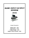
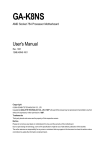
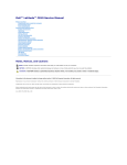
Dell™ Inspiron™ 700m/710m Service Manual Before You Begin
Recommended Tools
Turning Off Your Computer
Before Working Inside Your Computer
Computer Orientation
Screw Identification Placemat
Dell Diagnostics
When to Use the Dell Diagnostics
Starting the Dell Diagnostics
System Components
Battery
Removing a Battery
Installing the Battery
Palm Rest
Removing the Palm Rest
Replacing the Palm Rest
Memory, Modem, and Mini PCI Card Modules
Adding Memory
Replacing a Modem
Adding a Mini PCI Card
Installing Module Bay Devices
Keyboard
Removing the Keyboard
Replacing the Keyboard
Hard Drive
Replacing the Hard Drive
Returning a Hard Drive to Dell
Hinge Cover and Display Module
Removing the Hinge Cover
Replacing the Hinge Cover
Removing the Display Module
Replacing the Display
Coin-Cell Battery
Removing the Coin-Cell Battery
Replacing the Coin-Cell Battery
Cooling Fan
Removing the Cooling Fan
System Board
Removing the System Board
Replacing the System Board
Processor Thermal-Cooling Assembly
Removing the Processor Thermal-Cooling Assembly
Installing the Processor Thermal-Cooling Assembly
Processor
Removing the Processor
Installing the Processor
Optical Bay Latch
Removing the Optical Bay Latch
Replacing the Optical Bay Latch
Flashing the BIOS
Pin Assignments for I/O Connectors
USB Connector 2.0 (dual-stacked)
Video Connector
IEEE 1394 Connector
Model PP07S
Notes, Notices, and Cautions
NOTE: A NOTE indicates important information that helps you make better use of your computer.
NOTICE: A NOTICE indicates either potential damage to hardware or loss of data and tells you how to avoid the problem.
CAUTION: A CAUTION indicates a potential for property damage, personal injury, or death.
Abbreviations and Acronyms
For a complete list of abbreviations and acronyms, see the Dell Inspiron Help file.
If you purchased a Dell™ n Series computer, any references in this document to Microsoft® Windows® operating systems are not applicable.
Information in this document is subject to change without notice.
© 2005 Dell Inc. All rights reserved.
Reproduction in any manner whatsoever without the written permission of Dell Inc. is strictly forbidden.
Trademarks used in this text: Dell, the DELL logo, and Inspiron are trademarks of Dell Inc.; Microsoft and Windows are registered trademarks of Microsoft Corporation.
Other trademarks and trade names may be used in this document to refer to either the entities claiming the marks and names or their products. Dell Inc. disclaims any
proprietary interest in trademarks and trade names other than its own.
October 2005 Rev. A02
Back to Contents Page
Battery
Dell™ Inspiron™ 700m/710m Service Manual Removing a Battery
Installing the Battery
Removing a Battery
CAUTION: Before performing these procedures, disconnect the modem from the telephone wall jack.
CAUTION: Before you begin any of the procedures in this section, follow the safety instructions in the Product Information Guide.
NOTICE: If you remove the battery while the system is powered on and power cable is connected to an electrical outlet and then reinstall the battery
and disconnect the power cable within one and a half seconds, the system may shut down.
NOTICE: Do not replace the battery with the computer in standby mode.
1.
Ensure that the computer is turned off, set to the hibernate power management mode, or connected to an electrical outlet.
2.
Slide and hold the battery-bay latch release on the bottom of the computer, and then remove the battery from the bay.
1 battery-bay latch release
Installing the Battery
To install the battery, slide the battery into the bay until the latch release clicks.
Back to Contents Page
Back to Contents Page
Before You Begin
Dell™ Inspiron™ 700m/710m Service Manual Recommended Tools
Turning Off Your Computer
Before Working Inside Your Computer
Computer Orientation
Screw Identification Placemat
This section provides procedures for removing and installing the components in your computer. Unless otherwise noted, each procedure assumes that the
following conditions exist:
l
You have performed the steps in "Turning Off Your Computer" and "Before Working Inside Your Computer."
l
You have read the safety information in your Dell™ Product Information Guide.
l
A component can be replaced or—if purchased separately—installed by performing the removal procedure in reverse order.
Recommended Tools
The procedures in this document may require the following tools:
l
Small flat-blade screwdriver
l
Phillips screwdriver
l
Small plastic scribe
l
Flash BIOS update program floppy disk or CD
Turning Off Your Computer
NOTICE: To avoid losing data, save and close any open files and exit any open programs before you turn off your computer.
1.
Shut down the operating system:
a.
b.
Save and close any open files, exit any open programs, click the Start button, and then click Turn Off Computer.
In the Turn off computer window, click Turn off.
The computer turns off after the operating system shutdown process finishes.
2.
Ensure that the computer and any attached devices are turned off. If your computer and attached devices did not automatically turn off when you shut
down your operating system, press and hold the power button for 4 seconds.
Before Working Inside Your Computer
Use the following safety guidelines to help protect your computer from potential damage and to help ensure your own personal safety.
CAUTION: Before you begin any of the procedures in this section, follow the safety instructions in the Product Information Guide.
CAUTION: Handle components and cards with care. Do not touch the components or contacts on a card. Hold a card by its edges or by its metal
mounting bracket. Hold a component such as a processor by its edges, not by its pins.
NOTICE: Only a certified service technician should perform repairs on your computer. Damage due to servicing that is not authorized by Dell is not
covered by your warranty.
NOTICE: When you disconnect a cable, pull on its connector or on its strain-relief loop, not on the cable itself. Some cables have a connector with
locking tabs; if you are disconnecting this type of cable, press in on the locking tabs before you disconnect the cable. As you pull connectors apart, keep
them evenly aligned to avoid bending any connector pins. Also, before you connect a cable, ensure that both connectors are correctly oriented and
aligned.
NOTICE: To avoid damaging the computer, perform the following steps before you begin working inside the computer.
1.
Ensure that the work surface is flat and clean to prevent the computer cover from being scratched.
2.
Turn off your computer.
3.
If the computer is connected to a docking device (docked), undock it. See the documentation that came with your docking device for instructions.
NOTICE: To disconnect a network cable, first unplug the cable from your computer and then unplug it from the network wall jack.
4.
Disconnect any telephone or network cables from the computer.
5.
Close the display and turn the computer upside down on a flat work surface.
NOTICE: To avoid damaging the system board, you must remove the main battery before you service the computer.
6.
7.
Disconnect your computer and all attached devices from their electrical outlets, slide and hold the battery-bay latch release on the bottom of the
computer and remove the battery from the bay, and then press the power button to ground the system board.
Slide and hold the battery-bay latch release on the bottom of the computer, and then remove the battery from the bay.
1 battery latch release
8.
Remove any installed PC Cards or blanks from the PC Card slot.
9.
Remove the Secure Digital memory card, if installed, from the Secure Digital memory slot.
10.
Remove any installed modules.
11.
Remove the hard drive.
Computer Orientation
1
front
2
left
3
back
4
right
Screw Identification Placemat
When you are removing and replacing components, photocopy the placemat as a tool to lay out and keep track of the screws. The placemat provides the
number of screws and their sizes.
NOTICE: When reinstalling a screw, you must use a screw of the correct diameter and length. Ensure that the screw is properly aligned with its
corresponding hole, and avoid overtightening.
Cooling Fan:
Keyboard:
(3 each)
(2 each)
M2 x 3mm
M2.5 x 5mm
Display Module:
Modem:
(4 each)
(2 each)
M2.5 x 6 mm
M2 x 5mm
Palm Rest:
(1 each) (2 each)
(8 each)
M2 x 3 M2 x 5mm
M2.5 x 6mm
System Board:
(1 each)
M2 x 5mm
Back to Contents Page
Back to Contents Page
Flashing the BIOS
Dell™ Inspiron™ 700m/710m Service Manual To update the basic input/output system (BIOS):
1.
2.
Go to support.dell.com. If this is your first time to use the website, complete the
one-time registration.
Enter the Service Tag for your computer or select the appropriate Dell™ computer. Click Go.
3.
Click Downloads.
4.
Select the appropriate operating system and language for your computer.
5.
Select the FlashBIOS Updates download category.
Click Go.
6.
Click the BIOS link and follow the instructions to download the BIOS to your computer.
Back to Contents Page
Back to Contents Page
Processor Thermal-Cooling Assembly
Dell™ Inspiron™ 700m/710m Service Manual Removing the Processor Thermal-Cooling Assembly
Installing the Processor Thermal-Cooling Assembly
Removing the Processor Thermal-Cooling Assembly
CAUTION: Before you begin any of the procedures in this section, follow the safety instructions in the Product Information Guide.
NOTICE: Disconnect the computer and any attached devices from electrical outlets, and remove any installed batteries.
NOTICE: To avoid ESD, ground yourself by using a wrist grounding strap or by periodically touching an unpainted metal surface (such as the back
panel) on the computer.
NOTICE: Read "Before Working Inside Your Computer" before performing the following procedure.
1.
Remove the battery.
2.
Remove the keyboard.
3.
Disconnect the black and white antenna cables from the Mini PCI Card.
4.
Remove the display module.
5.
Remove the palm rest.
6.
Remove the system board.
NOTE: You can remove the microprocessor thermal-cooling assembly with the fan attached.
7.
Carefully turn the system board upside down.
8.
Disconnect the fan power cord from the system board.
1 processor thermal-cooling
assembly
2 cooling fan connector
3 cooling assembly support
plate
9.
Loosen in consecutive order the four captive screws labeled "1" through "4" that secure the microprocessor thermal-cooling assembly to the system
board.
10.
Rotate the microprocessor thermal-cooling assembly up toward the side of the computer and away from the system board.
11.
Lift the system board and rotate the cooling assembly support plate down and out from the video connector.
Installing the Processor Thermal-Cooling Assembly
1.
Slide the hole in the bottom cooling assembly plate over the video connector and carefully rotate the plate into place against the bottom of the system
board. Its holes should line up with holes in the system board.
2.
Seat the microprocessor thermal-cooling assembly in place. All four screws should match up with the screw holes in the system board and the bottom
cooling assembly plate. The fan should overhang the board to the right of the video connector.
3.
Reattach the fan power cord.
NOTICE: If the screws are not tightened in their numbered order, the processor may be damaged.
4.
Tighten the four captive screws labeled "1" through "4" in consecutive order.
Back to Contents Page
Back to Contents Page
Dell Diagnostics
Dell™ Inspiron™ 700m/710m Service Manual When to Use the Dell Diagnostics
Starting the Dell Diagnostics
When to Use the Dell Diagnostics
If you experience a problem with your computer, perform the checks in the "Solving Problems" section in your User's Guide or Owner's Manual and run the Dell
Diagnostics before you contact Dell for technical assistance. Running the Dell Diagnostics may help you resolve the problem without contacting Dell. If you do
contact Dell, the test results can provide important information for Dell's service and support personnel.
The Dell Diagnostics allows you to:
l
Perform tests on one or all devices.
l
Select tests based on a symptom of the problem you are having.
l
Choose how many times a test is run.
l
Suspend testing if an error is detected.
l
Access help information that describes the tests and devices.
l
Receive status messages that tell you whether tests completed successfully.
l
Receive error messages if problems are detected.
Starting the Dell Diagnostics
NOTICE: Use the Dell Diagnostics to test your Dell™ computer only. Using this program with other computers can result in error messages.
The Dell Diagnostics is located on a hidden diagnostic utility partition on your hard drive.
NOTE: If your computer cannot display a screen image, contact Dell.
1.
Shut down the computer.
2.
Connect the computer to an electrical outlet.
3.
Turn on the computer. When the DELL™ logo appears, press <F12>immediately. NOTE: If you cannot see anything on your display, hold down the <Fn> key and press the computer's power button to begin the Dell Diagnostics. The
computer automatically runs the Pre-boot System Assessment.
NOTE: If you see a message stating that no diagnostics utility partition has been found, run the Dell Diagnostics from your Drivers and Utilities CD.
If you wait too long and the Microsoft® Windows® logo appears, continue to wait until you see the Windows desktop. Then shut down your computer
through the Start menu and try again.
4.
When the boot device list appears, highlight Diagnostics and press <Enter>.
The computer runs the Pre-boot System Assessment, a series of initial tests of your system board, keyboard, hard drive, and display.
l
During the assessment, answer any questions that appear.
l
If a failure is detected, the computer stops and beeps. To stop the assessment and restart the computer, press <N>; to continue to the next
test, press <Y>; to retest the component that failed, press <R>.
l
If failures are detected during the Pre-boot System Assessment, write down the error code(s) and contact Dell before continuing on to the Dell
Diagnostics.
If the Pre-boot System Assessment completes successfully, you receive the message Booting Dell Diagnostic Utility Partition. Press any key to
continue.
5.
Press any key to start the Dell Diagnostics from the diagnostics utility partition on your hard drive.
6.
When the Dell Diagnostics Main Menu appears, select the test you want to run.
Dell Diagnostics Main Menu
After the Dell Diagnostics loads and the Main Menu screen appears, click the button for the option you want.
1.
Option
Function Express Test Performs a quick test of devices. This test typically takes 10 to 20 minutes and requires no interaction on your part. Run Express Test first to
increase the possibility of tracing the problem quickly.
Extended
Test
Performs a thorough check of devices. This test typically takes an hour or more and requires you to answer questions periodically.
Custom Test
Tests a specific device. You can customize the tests you want to run.
Symptom
Tree
Lists the most common symptoms encountered and allows you to select a test based on the symptom of the problem you are having.
If a problem is encountered during a test, a message appears with an error code and a description of the problem. Write down the error code and
problem description and follow the instructions on the screen.
2.
If you cannot resolve the error condition, contact Dell. See your User's Guide or Owner's Manual for contact information.
NOTE: The Service Tag for your computer is located at the top of each test screen. If you contact Dell, technical support will ask for your Service Tag.
3.
If you run a test from the Custom Test or Symptom Tree option, click the applicable tab described in the following table for more information.
Tab
Function Results
Displays the results of the test and any error conditions encountered.
Errors
Displays error conditions encountered, error codes, and the problem description.
Help
Describes the test and may indicate requirements for running the test.
Configuration Displays your hardware configuration for the selected device.
The Dell Diagnostics obtains configuration information for all devices from the system setup program, memory, and various internal tests, and
it displays the information in the device list in the left pane of the screen. The device list may not display the names of all the components
installed on your computer or all devices attached to your computer.
Parameters
4.
Allows you to customize the test by changing the test settings.
When the tests are complete, close the test screen to return to the Main Menu screen. To exit the Dell Diagnostics and restart the computer, close the
Main Menu screen.
Back to Contents Page
Back to Contents Page
Hinge Cover and Display Module
Dell™ Inspiron™ 700m/710m Service Manual Removing the Hinge Cover
Replacing the Hinge Cover
Removing the Display Module
Replacing the Display
CAUTION: Before you begin any of the procedures in this section, follow the safety instructions in the Product Information Guide.
NOTICE: Disconnect the computer and any attached devices from electrical outlets.
NOTICE: To avoid ESD, ground yourself by using a wrist grounding strap or by touching an unpainted metal surface on the computer.
NOTICE: Read "Before Working Inside Your Computer" before performing the following procedure.
Removing the Hinge Cover
CAUTION: Before you begin any of the procedures in this section, follow the safety instructions in the Product Information Guide.
1.
Remove the battery.
2.
Open the display all the way (180 degrees).
3.
Use a plastic flat screwdriver to slide the hinge caps away from the computer.
4.
Detach the two display latches on the back of the computer.
5.
Use plastic flat screwdriver to carefully pry up the latches on either side of the hinge cover.
1 hinge cover tab
2 hinge cover
3 hinge cover
6.
Carefully lift the hinge cover from the main unit and remove it from the main unit.
Replacing the Hinge Cover
1.
Open the computer all the way (180 degrees) so that it lies flat against your work surface.
2.
Connect the main cable.
3.
Place the hinge cover over the front display latches and rotate the cover down into place.
4.
Ensure that the two securing tabs on the outer edge of hinge cover are engaged in their respective slots.
NOTE: Make sure that the main cable and the speaker cables are tucked away from the hinge before you reattach the hinge cover.
5.
Slide the hinge caps over the display hinges and press down to snap the hinge caps into place.
6.
Close the display.
Removing the Display Module
1.
Remove the battery.
2.
Remove the keyboard.
3.
Disconnect the black and white antenna cables from the Mini PCI Card.
NOTE: You must detach the antenna cables from the Mini PCI Card before you remove the display module.
1
4.
Loosen the two M2 x 2mm captive screws and remove the upper memory module cover.
5.
Turn the computer over, and remove the two M2.5 x 6-mm screws from the bottom of the computer.
M2.5 x 6-mm screws (2)
6.
1
Remove the two M2.5x 6-mm screws from the back of the computer.
M2.5 x 6-mm screws (2)
7.
Turn the computer over and open the display 180 degrees.
8.
Disconnect the speaker cable connector.
9.
Gently pull on the display cable tab and disconnect the display cable on the left side of the unit.
10.
Disconnect the display cable on the right side of the unit.
NOTE: Make sure that the antenna cables are disconnected from the Mini PCI Card before removing the display module.
11.
Disconnect the antenna cables and make note of the path.
1 display cable tab
2 display module
3 speaker cable connector
4 display cable connector
NOTICE: Do not pull on the signal cable. Pull the signal connector to disconnect the cables.
12.
Disconnect the signal cable from the system board.
13.
If a tape secures the signal connector, remove it and disconnect the signal cable from the system board.
14.
Remove the display module out of the bottom case.
Replacing the Display
1.
Replace the display module into the bottom case and open the display 180 degrees.
2.
Replace the two M2.5 x 6-mm screws on the back of the computer.
3.
Connect the speaker cable connector.
4.
Connect the display cables on the left and right sides of the unit.
5.
Connect the antenna cables.
6.
Carefully thread the antenna cable back into place and connect both antenna connectors, matching the color codes.
7.
Connect the signal cable to the system board.
8.
If a tape secured the signal connector, replace it and connect the signal cable to the system board.
9.
Close the display and turn the computer over.
10.
Replace the two M2.5 x 6-mm screws from the bottom of the computer.
11.
Replace the upper memory module cover and tighten the two captive screws.
12.
Replace the keyboard.
13.
Replace the battery.
Back to Contents Page
Back to Contents Page
Cooling Fan
Dell™ Inspiron™ 700m/710m Service Manual Removing the Cooling Fan
Removing the Cooling Fan
CAUTION: Before you begin any of the procedures in this section, follow the safety instructions in the Product Information Guide.
NOTICE: Disconnect the computer and any attached devices from electrical outlets.
NOTICE: To avoid ESD, ground yourself by using a wrist grounding strap or by touching an unpainted metal surface on the computer.
NOTICE: Read "Before Working Inside Your Computer" before performing the following procedure.
1.
Remove the battery.
2.
Remove the keyboard.
3.
Disconnect the black and white antenna cables from the Mini PCI Card.
4.
Remove the display module.
5.
Remove the palm rest.
6.
Remove the system board.
7.
Remove the three M2 x 3-mm screws that secure the cooling fan to the system board.
1
system board connector
2
cooling fan connector
3
cooling fan
4
M2 x 3-mm screws (3)
8.
Remove the tape that secures the cooling fan cable to the fan.
NOTICE: Do not pull on the cooling fan cable. Pull from the cooling fan connector to disconnect the cable.
9.
10.
Disconnect the cooling fan cable from the system board connector.
Lift the cooling fan up and out of the bottom case.
Back to Contents Page
Back to Contents Page
Hard Drive
Dell™ Inspiron™ 700m/710m Service Manual Replacing the Hard Drive
Returning a Hard Drive to Dell
Replacing the Hard Drive
CAUTION: Before you begin any of the procedures in this section, follow the safety instructions in the Product Information Guide.
NOTICE: Disconnect the computer and any attached devices from electrical outlets.
NOTICE: To avoid ESD, ground yourself by using a wrist grounding strap or by touching an unpainted metal surface on the computer.
NOTICE: Read "Before Working Inside Your Computer" before performing the following procedure.
1.
Remove the battery.
2.
Loosen the three captive screws that secure the hard drive to the bottom case.
NOTE: Rubber grommets secure each screw to the hard drive so that you do not need to completely remove the screws.
1 captive screws (3)
2 hard drive cover
NOTICE: When the hard drive is not in the computer, store it in protective antistatic packaging. See "Protecting Against Electrostatic Discharge" in the
Product Information Guide.
3.
Loosen the two captive screws on the hard-drive securing bracket and remove the bracket.
4.
Pull the hard drive out of the computer using the pull tab.
1 hard-drive securing bracket
2 pull tab
3 hard drive
5.
Remove the new drive from its packaging.
Save the original packaging for storing or shipping the hard drive.
NOTICE: Use firm and even pressure to slide the drive into place. If you use excessive force, you may damage the connector.
6.
Insert the new drive at a 45-degree angle and rotate the drive into place.
7.
Press on the connector until the drive is fully seated.
8.
Replace the hard-drive securing bracket and tighten the two captive screws.
9.
Replace the hard drive cover and tighten the three captive screws.
10.
Install the operating system for your computer.
11.
Install the drivers and utilities for your computer.
Returning a Hard Drive to Dell
Return your old hard drive to Dell in its original or comparable foam packaging. Otherwise, the hard drive may be damaged in transit.
1 foam packaging
2 hard drive
Back to Contents Page
Back to Contents Page
Keyboard
Dell™ Inspiron™ 700m/710m Service Manual Removing the Keyboard
Replacing the Keyboard
Removing the Keyboard
CAUTION: Before you begin any of the procedures in this section, follow the safety instructions in the Product Information Guide.
NOTICE: Disconnect the computer and any attached devices from electrical outlets.
NOTICE: To avoid ESD, ground yourself by using a wrist grounding strap or by touching an unpainted metal surface on the computer.
NOTICE: Read "Before Working Inside Your Computer" before performing the following procedure.
1.
Remove the battery.
2.
Remove the hinge cover.
3.
Remove the two M2.5 x 5-mm keyboard securing screws.
NOTICE: The keycaps on the keyboard are fragile, easily dislodged, and time-consuming to replace. Be careful when removing and handling the
keyboard.
1
M2.5 x 5-mm securing screws (2)
4
ZIF connector
2
keyboard
5
ZIF connector tabs (2)
3
keyboard flex cable
6
securing tabs (4)
4.
Gently pull up either of the two keyboard locator tabs to pop up the keyboard.
5.
Pull the keyboard a small distance away from the front of the computer to release the four securing tabs located across the front edge of the keyboard.
6.
Rotate the keyboard toward the back of the computer and place it face down on the upper case.
NOTICE: Do not pull on the keyboard flex cable.
7.
Open the ZIF connector on the system board by pulling the ZIF connector tabs toward the back of the computer.
8.
Remove the keyboard flex cable from the ZIF connector.
9.
Lift the keyboard up and out of the computer.
Replacing the Keyboard
1.
Place the keyboard face down on the upper case and flip the keyboard flex cable toward the front of the computer.
NOTICE: To avoid damage to the connector pins, insert the keyboard flex cable evenly into the ZIF connector on the system board, and do not reverse
the keyboard flex cable.
2.
Ensure that the ZIF connector is open by pulling the ZIF connector tabs toward the back of the computer.
3.
Press the keyboard flex cable into the ZIF connector.
4.
Close the ZIF connector by pushing the ZIF connector tabs toward the front of the computer.
To aid with proper flex cable connection, a locator line has been added near the end of the flex cable. Press the cable into the connector until the line
disappears and hold the cable steady while you close the ZIF connector. (The white line may reappear after the connector is closed, which should not
indicate a problem with the connection.)
NOTICE: Position the keyboard flex cable so that it is not pinched when you replace the keyboard in the bottom case.
5.
6.
Turn the keyboard over and align the four securing tabs on the front of the keyboard with the slots on the upper case.
Ensure that all four keyboard securing tabs are engaged in their respective slots before trying to completely seat the keyboard. Press down on the left
and right <Alt> keys to help control tab/slot alignment.
When the keyboard appears to be completely seated, confirm that the front edge of the keyboard is aligned with the edge of the palm rest before
proceeding.
7.
Replace the two M2.5 x 5-mm securing screws on the keyboard.
8.
Replace the hinge cover.
Back to Contents Page
Back to Contents Page
Optical Bay Latch
Dell™ Inspiron™ 700m/710m Service Manual Removing the Optical Bay Latch
Replacing the Optical Bay Latch
Removing the Optical Bay Latch
CAUTION: Before you begin any of the procedures in this section, follow the safety instructions in the Product Information Guide.
NOTICE: Disconnect the computer and any attached devices from electrical outlets.
NOTICE: To avoid ESD, ground yourself by using a wrist grounding strap or by touching an unpainted metal surface on the computer.
NOTICE: Read "Before Working Inside Your Computer" before performing the following procedure.
1.
Remove the battery.
2.
Remove the memory module.
3.
Remove the Mini PCI card, if present.
4.
Remove the modem card, if present.
5.
Remove the hard drive.
6.
Remove the keyboard.
7.
Remove the display module.
8.
Remove the palm rest.
9.
Remove the system board.
10.
On the inside of the bottom case, use your fingers to unhook the latch from the bottom case and the snap tabs, catching the optical-latch release
button on the outside of the bottom case.
1 optical lock latch
2 spring
3 bottom case
4 optical-latch release
button
Replacing the Optical Bay Latch
1.
Snap in the new latch button from behind the bottom case, making certain that the snap tabs are fully engaged in the latch.
NOTE: The optical latch release has springs and should be installed on the bottom case.
2.
Ensure that the newly installed latch moves smoothly and freely when pushed and released.
Back to Contents Page
Back to Contents Page
Palm Rest
Dell™ Inspiron™ 700m/710m Service Manual Removing the Palm Rest
Replacing the Palm Rest
Removing the Palm Rest
CAUTION: Before you begin any of the procedures in this section, follow the safety instructions in the Product Information Guide.
NOTICE: Disconnect the computer and any attached devices from electrical outlets.
NOTICE: To avoid ESD, ground yourself by using a wrist grounding strap or by touching an unpainted metal surface on the computer.
NOTICE: Read "Before Working Inside Your Computer" before performing the following procedure.
1.
Remove the battery.
2.
Remove the keyboard.
3.
Disconnect the black and white antenna cables from the Mini PCI Card.
4.
Remove the display module.
5.
Turn the computer over, loosen the two captive screws, and remove the upper memory module cover.
6.
Remove the eight M2.5 x 6-mm screws from the bottom of the computer and the one M2 x 3-mm screw from the optical bay.
7.
Turn the computer over, and with the bottom of the case resting on a flat surface, carefully separate the palm rest from the lower case.
a.
Disconnect the touch pad cable from the system board.
b.
Remove the two M2 x 5-mm screws from the palm rest.
c.
Carefully detach the palm rest from the bottom case.
1 palm-rest flex cable
4 M2 x 5-mm screws (2)
2 ZIF connector
5 palm-rest
3 ZIF connector tabs (2) 6 bottom case
8.
Lift the ZIF connector, and disconnect the palm-rest flex cable from its ZIF connector on the system board.
9.
Lift the palm rest up and out of the computer.
Replacing the Palm Rest
To aid with proper flex cable connection, a locator line has been added near the end of the palm-rest flex cable. When replacing the palm-rest flex cable, press
the cable into the connector until the line aligns with the system board and hold it steady while you snap the ZIF connector down. (The locator line may
reappear after the connector is closed, which should not indicate a problem with the connection.)
Back to Contents Page
Back to Contents Page
Pin Assignments for I/O Connectors
Dell™ Inspiron™ 700m/710m Service Manual USB Connector 2.0 (dual-stacked)
Video Connector
IEEE 1394 Connector
USB Connector 2.0 (dual-stacked)
Pin Signal
1
VCC
2
Data–
3
Data+
4
GND
Video Connector
Pin Signal Pin Signal
1
RED
2
GREEN 10
9
CRT_VCC
GND
3
BLUE
11
NC
4
NC
12
DAT_DDC2
5
GND
13
HSYNC
6
GND
14
VSYNC
7
GND
15
CLK_DDC2
8
GND
IEEE 1394 Connector
1
TPB–
2
TPB+
3
TPA–
4
TPA+
Back to Contents Page
Back to Contents Page
Processor
Dell™ Inspiron™ 700m/710m Service Manual Removing the Processor
Installing the Processor
Removing the Processor
CAUTION: Before you begin any of the procedures in this section, follow the safety instructions in the Product Information Guide.
NOTICE: Disconnect the computer and any attached devices from electrical outlets.
NOTICE: To avoid ESD, ground yourself by using a wrist grounding strap or by touching an unpainted metal surface on the computer.
NOTICE: Read "Before Working Inside Your Computer" before performing the following procedure.
1.
Remove the battery.
2.
Remove the keyboard.
3.
Disconnect the black and white antenna cables from the Mini PCI Card.
4.
Remove the display module.
5.
Remove the palm rest.
6.
Remove the system board.
7.
Gently turn the system board upside down.
8.
Remove the processor thermal-cooling assembly.
NOTICE: When removing the microprocessor module, pull the module straight up. Be careful not to bend the pins on the microprocessor module.
To loosen the ZIF socket, use a small, flat-blade screwdriver and rotate the ZIF-socket cam screw counterclockwise until it comes to the cam stop.
9.
1
processor
2
cam stop
3
ZIF socket cam screw
NOTE: The ZIF-socket cam screw secures the microprocessor to the system board. Take note of any directional indicators on the ZIF-socket cam screw.
10.
Lift out the microprocessor module.
Installing the Processor
NOTICE: Ensure that the cam lock is in the fully open position before seating the microprocessor module. Seating the microprocessor module properly in
the ZIF socket does not require force.
NOTICE: A microprocessor module that is not properly seated can result in an intermittent connection or permanent damage to the microprocessor and
ZIF socket.
1.
Align the pin-1 corner of the microprocessor module with the pin-1 corner of the ZIF socket, and insert the microprocessor module.
NOTE: The pin-1 corner of the microprocessor module has a triangle that aligns with the triangle on the pin-1 corner of the ZIF socket.
NOTICE: You must position the microprocessor module correctly in the ZIF socket to avoid permanent damage to the module and the socket.
When the microprocessor module is correctly seated, all four corners are aligned at the same height. If one or more corners of the module are higher
than the others, the module is not seated correctly.
2.
Tighten the ZIF socket by turning the cam screw clockwise to secure the microprocessor module to the system board.
3.
Perform the steps in "Removing the Processor" in reverse order, beginning with step step 8.
4.
Update the BIOS using a flash BIOS update program floppy disk or CD. For instructions on how to flash the BIOS, see "Flashing the BIOS."
Back to Contents Page
Back to Contents Page
Coin-Cell Battery
Dell™ Inspiron™ 700m/710m Service Manual Removing the Coin-Cell Battery
Replacing the Coin-Cell Battery
Removing the Coin-Cell Battery
CAUTION: Before you begin any of the procedures in this section, follow the safety instructions in the Product Information Guide.
NOTICE: Disconnect the computer and any attached devices from electrical outlets.
NOTICE: To avoid ESD, ground yourself by using a wrist grounding strap or by touching an unpainted metal surface on the computer.
NOTICE: Read "Before Working Inside Your Computer" before performing the following procedure.
1.
Remove the battery.
2.
Remove the keyboard.
3.
Remove the display module.
4.
Remove the palm rest.
NOTICE: Do not pull on the coin-cell battery cable. Pull from the coin-cell battery connector to disconnect the cable.
5.
Disconnect the coin-cell battery cable from the system board connector.
1 system board connector
2 coin-cell battery connector
3 system board
4 coin-cell battery
6.
Pry the coin-cell battery free from the bottom case. The coin-cell battery is attached to the bottom case with a piece of adhesive tape.
7.
Remove any remnants of the adhesive tape from the bottom case.
Replacing the Coin-Cell Battery
1.
Connect the coin-cell battery connector to the system board connector.
2.
Press the coin-cell battery into place on the bottom case.
3.
Ensure that the cable is routed correctly as shown to avoid damaging the cable.
4.
Update the CMOS settings.
Back to Contents Page
Back to Contents Page
System Board
Dell™ Inspiron™ 700m/710m Service Manual Removing the System Board
Replacing the System Board
Removing the System Board
CAUTION: Before you begin any of the procedures in this section, follow the safety instructions in the Product Information Guide.
NOTICE: Disconnect the computer and any attached devices from electrical outlets.
NOTICE: To avoid ESD, ground yourself by using a wrist grounding strap or by touching an unpainted metal surface on the computer.
NOTICE: Read "Before Working Inside Your Computer" before performing the following procedure.
1.
Remove the battery.
2.
Remove the module bay device.
3.
Remove the hard drive.
4.
Remove the Mini PCI card, if present.
5.
Remove the modem card, if present.
6.
Remove the keyboard.
7.
Remove the upper memory module.
8.
Remove the memory module.
9.
Remove the display module.
10.
Remove the palm rest.
1 hex screws (2)
4 system board
2 coin-cell battery connector
5 modem cable connector
3 upper case M2 x 5-mm screw
11.
Remove the two 5 mm hex nuts on either side of the video connector located on the left side of the computer.
12.
Disconnect the coin-cell battery connector and the modem cable connector from the main board.
13.
Remove the M2 x 5-mm screw that secures the system board to the bottom case.
14.
Lift the system board up from the right side and out of the bottom case.
15.
Gently turn the system board upside down.
16.
Remove the processor thermal-cooling assembly.
17.
Remove the processor.
Replacing the System Board
1.
Install the processor.
2.
Install the processor thermal-cooling assembly.
3.
Turn the system board over and place it in the bottom case.
NOTE: Route cables so that they will not be crimped or pinched when the complete assembly is put back together.
4.
Reconnect all the cables to the system board ZIF connectors.
5.
Reinstall the M2 x 5-mm screw that secures the system board to the bottom case.
NOTE: After replacing the system board, enter the computer Service Tag into the BIOS of the replacement system board.
Back to Contents Page
Back to Contents Page
System Components
Dell™ Inspiron™ 700m/710m Service Manual NOTICE: Only a certified service technician should perform repairs on your computer. Damage due to servicing that is not authorized by Dell is not
covered by your warranty.
NOTICE: Unless otherwise noted, each procedure in this manual assumes that a part can be replaced by performing the removal procedure in reverse
order.
1 display with integrated speakers (2) 10 bottom case
2 hinge cover
11 battery
3 keyboard
12 modem
4 palm rest
13 mini PCI card
5 hard drive
14 upper memory module cover
6 system board
15 cooling fan assembly plate
7 optical drive
16 CPU
8 memory module
17 cooling fan assembly
9 coin-cell battery
Back to Contents Page
Back to Contents Page
Dell™ Inspiron™ 700m Service Manual NOTE: A NOTE indicates important information that helps you make better use of your computer.
NOTICE: A NOTICE indicates either potential damage to hardware or loss of data and tells you how to avoid the problem.
CAUTION: A CAUTION indicates a potential for property damage, personal injury, or death.
For a complete list of abbreviations and acronyms, see the Dell Inspiron Help file.
If you purchased a Dell™ n Series computer, any references in this document to Microsoft® Windows® operating systems are not applicable.
Information in this document is subject to change without notice.
© 2005 Dell Inc. All rights reserved.
Reproduction in any manner whatsoever without the written permission of Dell Inc. is strictly forbidden.
Trademarks used in this text: Dell, the DELL logo, and Inspiron are trademarks of Dell Inc.; Microsoft and Windows are registered trademarks of Microsoft Corporation.
Other trademarks and trade names may be used in this document to refer to either the entities claiming the marks and names or their products. Dell Inc. disclaims any
proprietary interest in trademarks and trade names other than its own.
February 2005 Rev. A01
Back to Contents Page
Back to Contents Page
Memory Module, Modem, Mini PCI Card and Module Bay Device
Dell™ Inspiron™ 700m/710m Service Manual Adding Memory
Replacing a Modem
Adding a Mini PCI Card
Installing Module Bay Devices
Adding Memory
You can increase your computer memory by installing a memory module on the system board. See the "Specifications" section in your Owner's Manual for
information on the memory supported by your computer. Be sure to add only a memory module that is intended for your computer.
Your computer has two memory modules:
l
Lower memory module located under the memory module cover on the bottom of the base
l
Upper memory module located under the keyboard
CAUTION: Before you begin any of the procedures in this section, follow the safety instructions in the Product Information Guide.
NOTICE: Read "Before Working Inside Your Computer" before performing the following procedure.
NOTE: Memory modules purchased from Dell are covered under your computer warranty.
Installing A Lower Memory Module
1.
Ensure that the work surface is flat and clean to prevent scratching the computer cover.
2.
Save and close any open files, exit any open programs, and shut down the computer.
3.
Disconnect the computer from the electrical outlet.
4.
Wait 10 to 20 seconds, and then disconnect any attached devices.
5.
Remove the battery and any installed PC Cards.
NOTICE: Handle components and cards by their edges, and avoid touching pins and contacts. Ground yourself by touching a metal connector on the
back of the computer. Continue to ground yourself periodically during this procedure.
6.
Turn the computer over, loosen the two captive screws on the memory module cover, and then remove the cover.
1
memory module cover
2
captive screws (2)
NOTICE: To prevent damage to the memory module connector, do not use tools to spread the memory module securing clips.
7.
If you are replacing a memory module, remove the existing module.
NOTICE: Handle components and cards by their edges, and avoid touching pins and contacts. Ground yourself by touching a metal connector on the
back of the computer. Continue to ground yourself periodically during this procedure.
8.
a.
Use your fingertips to carefully spread apart the securing clips on each end of the memory module connector until the module pops up.
b.
Remove the module from the connector.
Ground yourself and install the new memory module:
a.
Align the notch in the module edge connector with the tab in the center of the connector slot.
b.
Slide the module firmly into the slot at a 45-degree angle, and rotate the module down until it clicks into place. If you do not hear the click,
remove the module and reinstall it.
NOTE: If the memory module is not installed properly, the computer may not boot properly. No error message indicates this failure.
9.
Replace the cover.
NOTICE: If the cover is difficult to close, remove the module and reinstall it. Forcing the cover to close may damage your computer.
10.
Insert the battery into the battery bay, or connect the AC adapter to your computer and an electrical outlet.
11.
Turn on the computer.
As the computer boots, it detects the additional memory and automatically updates the system configuration information.
To confirm the amount of memory installed in the computer, click the Start button, click Help and Support, and then click Computer Information.
Installing An Upper Memory Module
1.
Ensure that the work surface is flat and clean to prevent scratching the computer cover.
2.
Save and close any open files, exit any open programs, and shut down the computer.
3.
Disconnect the computer from the electrical outlet.
4.
Wait 10 to 20 seconds, and then disconnect any attached devices.
5.
Remove the battery and any installed PC Cards.
NOTICE: Handle components and cards by their edges, and avoid touching pins and contacts. Ground yourself by touching a metal connector on the
back of the computer. Continue to ground yourself periodically during this procedure.
6.
Remove the keyboard.
7.
Loosen the two captive screws, and remove the upper memory module cover.
1
upper memory module cover
2
captive screws (2)
NOTICE: To prevent damage to the memory module connector, do not use tools to spread the memory module securing clips.
8.
If you are replacing a memory module, remove the existing module.
NOTICE: Handle components and cards by their edges, and avoid touching pins and contacts. Ground yourself by touching a metal connector on the
back of the computer. Continue to ground yourself periodically during this procedure.
9.
a.
Use your fingertips to carefully spread apart the securing clips on each end of the memory module connector until the module pops up.
b.
Remove the module from the connector.
Ground yourself and install the new memory module:
a.
Align the notch in the module edge connector with the tab in the center of the connector slot.
b.
Slide the module firmly into the slot at a 45-degree angle, and rotate the module down until it clicks into place. If you do not hear the click,
remove the module and reinstall it.
NOTE: If the memory module is not installed properly, the computer may not boot properly. No error message indicates this failure.
10.
Insert the securing tabs on the upper memory module cover into the notches above the memory module connector and tighten the captive screws.
NOTICE: If the upper memory module cover is difficult to replace, remove the module and reinstall it. Forcing the cover to close may damage your
computer.
11.
Replace the keyboard.
12.
Insert the battery into the battery bay, or connect the AC adapter to your computer and an electrical outlet.
13.
Turn on the computer.
To confirm the amount of memory installed in the computer, click the Start button, click Help and Support, and then click Computer Information.
Replacing a Modem
CAUTION: Before performing any of the procedures listed below, read and follow the safety instructions in the Product Information Guide.
NOTICE: Read "Before Working Inside Your Computer" before performing the following procedure.
1.
Ensure that the work surface is flat and clean to prevent scratching the computer cover.
2.
Save and close any open files, exit any open programs, and then shut down the computer.
3.
Disconnect the computer from the electrical outlet.
4.
Wait 10 to 20 seconds and then disconnect any attached devices.
5.
Remove the battery, any installed PC Cards or blanks, and devices.
NOTICE: Handle modules by their edges, and do not touch the components on a module. Ground yourself by touching a metal connector on the back of
the computer, and continue to do so periodically during this procedure.
6.
Turn the computer over and loosen the two captive screws on the modem cover, and remove the cover.
1
Mini PCI card and modem cover
2
captive screws (2)
7.
If a modem is not already installed, go to step 10.
8.
If you are replacing a modem, remove the existing modem:
a.
Remove the two M2 x5-mm screws securing the modem to the system board, and set them aside.
b.
Pull straight up on the attached pull-tab to lift the modem out of its connector on the system board, and disconnect the modem cable.
1
M2 x 5-mm modem screws (2)
2
modem
3
modem cable connector
4
system board connector
9.
Connect the modem cable to the modem.
NOTICE: The connectors are keyed to ensure correct insertion. If you feel resistance, check the connectors and realign the card.
10.
Align the modem with the screw hole and press the modem into the connector on the system board.
11.
Install the two M2 x 5-mm screws to secure the modem to the system board.
12.
Replace the cover.
Adding a Mini PCI Card
If you ordered a Mini PCI card with your computer, the card is already installed.
CAUTION: Before performing any of the procedures listed below, read and follow the safety instructions in the Product Information Guide.
NOTICE: Read "Before Working Inside Your Computer" before performing the following procedure.
1.
Ensure that the work surface is flat and clean to prevent scratching the computer cover.
2.
Save and close any open files, exit any open programs, and shut down the computer.
3.
Disconnect the computer from the electrical outlet.
4.
Wait 10 to 20 seconds and then disconnect any attached devices.
5.
Remove the battery, any installed PC Card or blanks, and devices.
NOTICE: Handle modules and cards by their edges, and avoid touching pins and contacts. Ground yourself by touching a metal connector on the back of
the computer. Continue to ground yourself periodically during this procedure.
6.
Turn the computer over.
7.
Loosen the two captive screws on the cover, and remove the cover.
1 Mini PCI card and modem cover
2 captive screw (2)
8.
If a Mini PCI card is not already installed, go to step 10.
9.
If you are replacing a Mini PCI card, remove the existing card:
a.
Disconnect the Mini PCI card from the attached cables.
1 antenna cable connectors
b.
Release the Mini PCI card by spreading the metal securing tabs until the card pops up slightly.
1 Mini PCI card
2 release latches (2)
c.
Lift the Mini PCI card out of its connector.
NOTICE: To avoid damaging the Mini PCI card, never place cables on top of or under the card.
10.
To replace a Mini PCI card, align the card with the connector at a 45-degree angle, and press the Mini PCI card into the connector.
11.
Lower the Mini PCI card toward the inner tabs to approximately a 20-degree angle.
12.
Continue lowering the Mini PCI card until it snaps into the inner tabs of the connector.
1
Mini PCI card
2
connector
13.
Connect the antenna cable to the antenna connector on the Mini PCI card.
NOTICE: The connectors are keyed for correct insertion. If you feel resistance, check the connectors and realign the card.
1 antenna cable connectors
14.
Replace the cover and tighten the screws.
Installing Module Bay Devices
CAUTION: Before you begin any of the procedures in this section, follow the safety instructions located in the Product Information Guide.
You can install devices such as a DVD drive, CD-RW/DVD drive, or DVD+RW in the module bay.
Removing and Installing Devices While the Computer Is Turned Off
NOTICE: To prevent damage to devices, store them in a safe, dry place when they are not installed in the computer. Avoid pressing down on them or
placing heavy objects on top of them.
1.
Slide and hold the device latch release.
2.
Pull the device out of the module bay.
3.
Push the new device into the bay until it clicks.
Removing and Installing Devices While the Computer Is Running
1.
Before ejecting the device, double-click the Safely Remove Hardware icon on the taskbar, click the device you want to eject, and click Stop.
NOTICE: To prevent damage to devices, store them in a safe, dry place when they are not installed in the computer. Avoid pressing down on them or
placing heavy objects on top of them.
2.
Slide and hold the device latch release.
3.
Pull the device out of the module bay.
4.
Push the new device into the bay until it clicks.
The operating system automatically recognizes the device.
Back to Contents Page