1
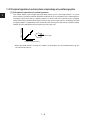
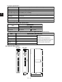
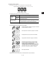
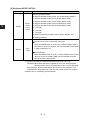
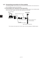
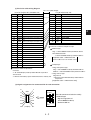
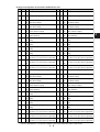
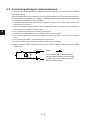
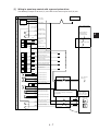
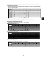
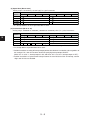
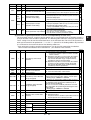
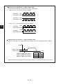
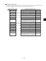
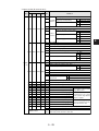
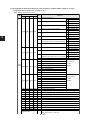
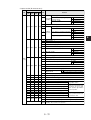
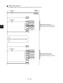
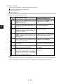
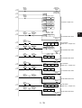
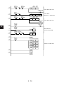
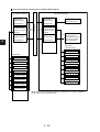
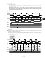
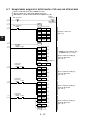
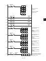
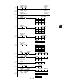
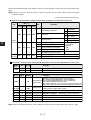
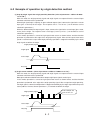
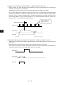
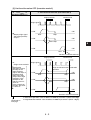
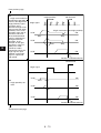
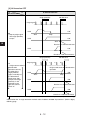
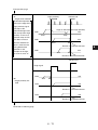
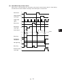
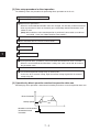
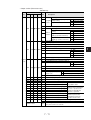
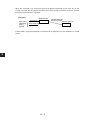
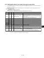
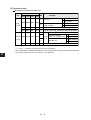
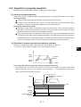
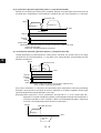
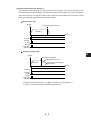
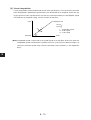
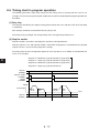
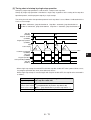
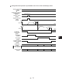
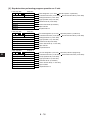
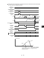
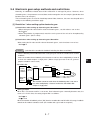
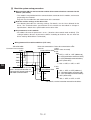
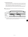
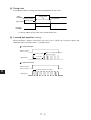
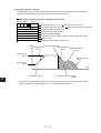
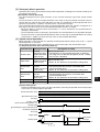
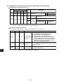
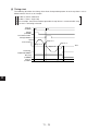
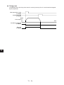
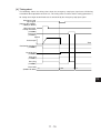
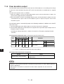
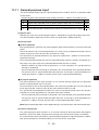
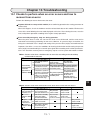
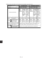
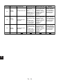
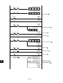
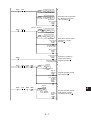
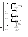
11-9 Clear deviation output
Clear deviation output (CN2/3 pin Nos.6 and 18) turns ON for about 20 ms according to the change
in state of the clear deviation relay from OFF to ON. Clear deviation is enabled only in a stopped
state.
The state of the present value is as follows:
1. When this module is used in an open loop control system, and clear deviation is output, the
present value (origin) becomes unconfirmed.
2. When this module is used in a closed loop control system, and clear deviation is output, the value
calculated from the pulse value of the feedback system is input to the pulse value of the
instruction system.
Clear deviation output is automatically output at the following conditions in addition to the ON/OFF
state of this relay:
1. Clear deviation output turns ON for about 20 ms when zero return is completed.
2. Clear deviation output turns ON for about 20 ms together with suspension of pulse output when an
emergency stop is executed.
(according to setting of parameter 1 (address A+0000 bit 5) "Emergency stop input function
selection")
(1) Assignment of operation relay (assignment of special I/O data area)
I/O
11
Byte address of data memory
Function
Bit
X-axis Y-axis Z-axis* A-axis*
Input
0000 0020 0040 0060
(PC←PS)
2
Busy flag
Output 0201 0221 0241 0261
(PC→PS)
5
Busy state
0 Clear deviation
1 Non-busy state
0 OFF
1 ON
*JW-14PS only
• "****" in N+**** indicates the numerical value of the address.
(2) External I/O connector pin arrangement
Name
Pin No.
6 (X-/Z-axes) / 18 (Y-/A-axes)
Clear deviation output/origin alignment instruction
output (24 V)
Note
• When the servo is powered ON with a deviation having occurred, the motor suddenly operates,
which is dangerous.
When only the servo driver is turned OFF and the motor is operated, be sure to clear the
deviation.
11 - 20