1
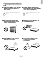
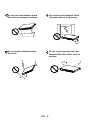
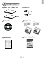
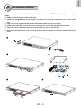
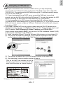
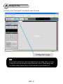
NR8201/8301
H.264 Compatible with VAST CMS Lockable HDD & Rack Mount Design
NR8201
4-CH Viewing & Recording
External eSATA Interface
NR8301
8-CH Viewing & Recording
RAID 0, 1 Scalable Storage
Rev. 1.1
P/N: 625013601G Ver.1.1
Copyright c 2011 VIVOTEK INC. All rights reserved.
New Taipei City
English
Warning Before Installation
Power off the Network Video Recorder
as soon as it is found smoking or
smelt unusual.
Contact your distributor when such cases
happen.
Power
PoE
Status
HDD
WA N
LAN1
LAN2
LAN3
LAN4
LAN5
LAN6
LAN7
Contact your distributor when such cases
happen.
Refer to your user's manual for the
operating temperature.
Do not place the Network Video
Recorder around the heat sources,
such as television or oven.
NR8301 Network Video Recorder
Keep the Network Video Recorder
away from water. If the Video Recorder
is wet, power off immediately.
LAN8
NR8301
Network
Video
Recorder
Power
Status
Keep the Network Video Recorder
away from direct sunlight.
PoE
WAN
HDD
LAN1
LAN2
LAN3
LAN4
LAN5
Network
Video
Recorder
Power
Status
Network
Video
Recorder
Power
Status
PoE
WAN
HDD
LAN1
LAN2
LAN3
LAN4
LAN5
LAN6
LAN7
LAN7
LAN8
Do not place the Network Video
Recorder in high humidity
environments.
NR8301
NR8301
LAN6
LAN8
EN - 1
PoE
WAN
HDD
LAN1
LAN2
LAN3
LAN4
LAN5
LAN6
LAN7
LAN8
Do not touch the Network Video
Recorder when it's lightening.
Do not place the Network Video
Recorder on unsteady surfaces.
Power
NR8301 Network Video
PoE
Recorder
WAN
Status
LAN1
LAN2
LAN3
LAN4
LAN5
LAN6
LAN7
LAN8
HDD
NR8301
Network
Video
Recorder
Power
Status
Do not drop the Network Video
Recorder.
NR8301
Network
Video
Recorder
Power
Status
LAN7
LAN6
LAN5
LAN4
LAN3
LAN2
LAN1
PoE
WAN
Power
Video
Network
WAN
LAN1
LAN2
LAN3
LAN4
LAN5
LAN6
LAN7
LAN8
Do not insert any object into the
Network Video Recorder, such as
needles.
LAN8
HDD
Recorder
PoE
HDD
Status
NR8301
EN - 2
PoE
WAN
HDD
LAN1
LAN2
LAN3
LAN4
LAN5
LAN6
LAN7
LAN8
English
1
Package Contents
NR8201 (4CH) or NR8301 (8CH)
Power Cord
NR8201
Power
Status
PoE
WAN
HDD
LAN1
LAN2
LAN3
LAN4
NR8201
Network
Video
Recorder
NR8301
NR8301
Network
Video Recorder
Power
Status
PoE
WAN
HDD
LAN1
LAN2
LAN3
LAN4
LAN5
LAN6
LAN7
LAN8
Rack Mount Kit
Software CD
NR8201:
Rack Mount Ear x 2
Screws x 4 (Black)
Screws x 4 (Grey)
Key x 2
NR8301:
Rack Mount Ear x 2
Screws x 4 (Black)
Screws x 8 (Grey)
Key x 2
510000210G
Quick Installation Guide
Warranty Card
EN - 3
2
Physical Description
NR8301
Removable & Lockable Hard Disk Trays x 2
Status Indicator
USB Socket
Power
PoE
Status
HDD
NR8301 Network Video Recorder
WAN
LAN 1
LAN 2
LAN 3
LAN 4
LAN5
LAN6
LAN7
LAN8
Ethernet 10/100 RJ45 Socket x 8 (LAN);
Gigabit Ethernet RJ45 Socket x 1 (WAN)
Power Cord Socket
POWER
AC IN 100V-240V
Power Button
RESET
LAN2
LAN4
LAN6
LAN8
LAN1
LAN3
LAN5
LAN7
WAN
1 2 3 4 5 6 7 8 9 10 1112
Recessed Reset Button
General I/O Terminal Block
NR8201
Status Indicator
Power
PoE
Status
HDD
Removable & Lockable Hard Disk Tray x 1
NR8201 Network Video Recorder
WAN
LAN1
LAN2
LAN3
LAN4
USB Socket
Ethernet 10/100 RJ45 Socket x 4 (LAN);
Gigabit Ethernet RJ45 Socket x 1 (WAN)
eSATA Socket
Power Cord Socket
POWER
Power Button
AC IN 100V-240V
RESET
eSATA
LAN1
LAN3
LAN5
LAN7
WAN
1 2 3 4 5 6 7 8 9 10 1112
Recessed Reset Button
General I/O Terminal Block
EN - 4
English
3
Hardware Installation
Before using the Network Video Recorder, please prepare SATA hard disk(s) for recording
video.
1. Make sure the power is disconnected.
2. Install the supplied rack mount ears if you want to install the enclosure into a rack cabinet.
3. Open the drive tray bezel as shown below and remove the drive trays.
4. Install your hard disk to the drive tray, and secure it with the supplied four screws.
5. Open the drive tray bezel and insert hard disk(s) into the drive bays.
6. Use the supplied bezel key to lock the drive trays in place to prevent unauthorized access.
2
NR8301
Network
Video Recorder
Power
Status
PoE
WAN
HDD
LAN1
LAN2
LAN3
LAN4
LAN5
LAN6
LAN7
LAN8
4
3
NR8301
Network
Video Recorder
Power
Status
PoE
WAN
HDD
LAN1
LAN2
LAN3
LAN4
LAN5
LAN6
LAN7
5
LAN8
6
NR8301
Network
Video Recorder
Power
Status
PoE
WAN
HDD
LAN1
LAN2
LAN3
LAN4
LAN5
LAN6
LAN7
NR8301
LAN8
Network
Video Recorder
Power
Status
EN - 5
PoE
WAN
HDD
LAN1
LAN2
LAN3
LAN4
LAN5
LAN6
LAN7
LAN8
4
Network Deployment
1. Connect the supplied power cable from the Network Video Recorder (NVR) to a power
outlet.
2. Push the power button to run the NVR.
3. Connect network cameras to the NVR’s PoE LAN ports. Connect a management PC to the
WAN port directly or via LAN. The NVR comes with an embedded DHCP server for its LAN
ports. It is necessary to configure the LAN ports and the WAN port into different Class C
subnets, e.g., 192.168.100.xxx for LAN and 192.168.4.xxx for WAN.
4. If you want to access NVR over the Internet, connect the NVR to the Internet via the
WAN port.
5. If you have external devices such as sensors and alarms, make connections from the
general I/O terminal block.
NVR embedded
DHCP server
POWER
AC IN 100V-240V
2
RESET
1
LAN2
LAN4
LAN6
LAN8
LAN1
LAN3
LAN5
LAN7
WAN
5
1 2 3 4 5 6 7 8 9 10 1112
Private LAN
LAN
3
Cable, DSL
Modem, or router
Internet
Network Camera
(PoE)
Powe
x8
r/MIC
Activity
Powe
r/MIC
Activity
Class C
subnet #0
3
Network
Video Recorder
Power
Status
PoE
WAN
HDD
LAN1
LAN2
LAN3
LAN4
LAN5
LAN6
LAN7
LAN8
NR8301
Power Supply
4-CH PoE
Data Transmitting
Power
Status
PoE
WAN
HDD
LAN1
LAN2
LAN3
LAN4
NR8201
Network
Video
Recorder
NR8201
Class C
subnet #1
5
8-CH PoE
Data Transmitting
NR8301
4
Power Supply
EN - 6
Management
PC
1: Power
2: Relay output COM
3: Relay output N.O.
4: Digital Input 1
5: Digital Input 1 Ground
6: Digital Input 2
7: Digital Input 2 Ground
8: Digital Input 3
9: Digital Input 3 Ground
10: Digital Input 4
11: Digital Input 4 Ground
12: Ground
English
5
Assigning an IP Address
1. 1-1. If your local network does not have a DHCP server, you may temporarily
connect a PC to a LAN port for initial configuration. The NVR comes with a default IP,
192.168.100.1. You can access the NVR server using this IP, and then manaully assign
an IP to the NVR WAN port.
1-2. If your local network has a DHCP server, connect the WAN port to your local
network, and use the IW2 utility to find the NVR server IP. You may then access the NVR
server by entering the discovered IP in the address bar of a web browser.
1-3 Once connected to the NVR server, please keep the LAN setting as default.
You may let DHCP server assign an IP to your NVR WAN port - or - if you need to access
NVR over Internet, please configure a WAN port IP address in Router/firewall using port
forwarding or DMZ.
2. If you need to access NVR over the Internet, please assign a WAN IP address in the
configuration page. You may use DDNS for Internet access. There are three ways to get
WAN IP address: DHCP (Dynamic IP), Static IP address, and PPPoE (DSL).
If your network environment is DHCP, you can use VIVOTEK Installation Wizard 2 (IW2)
to discover the IP address for the WAN port.
(1) Install “Installation Wizard 2” from the Software Utility directory on the software CD.
(2) The program will conduct an analysis of your network environment. After your network is analyzed, please click on the “Next” button to continue the program.
Installation
Wizard 2
(3) The program will search the VIVOTEK Network Devices on the same LAN.
(4) After searching, the main installer window will pop up.
Click on the MAC that matches the one labeled on your device to connect to the Network Video Recorder via Internet Explorer.
00-02-D1-07-89-3F
192.168.5.131
NR8301
0002D107893F
NR8301
0002D107893F
3. Use the WAN IP address to access the Network Video Recorder from the Internet.
EN - 7
6
Ready to Use
Following is the Homepage of the Network Video Recorder.
Configuration page
Note
If you want to record live video and playback the recorded video, you have
to add devices to the Network Video Recorder on the Configuration page.
For further setup, please refer to user's manual on the software CD.
EN - 8
NR8201/8301
H.264 Compatible with VAST CMS Lockable HDD & Rack Mount Design
NR8201
4-CH Viewing & Recording
External eSATA Interface
NR8301
8-CH Viewing & Recording
RAID 0, 1 Scalable Storage
Rev. 1.1
P/N: 625013601G Ver.1.1
Copyright c 2011 VIVOTEK INC. All rights reserved.
New Taipei City


![Cover [NR7401]_o](http://vs1.manualzilla.com/store/data/006290720_1-4f23ff4bcdfa148ab77552381ec65ce5-150x150.png)
![Cover [NR7401]_o](http://vs1.manualzilla.com/store/data/006042530_1-185ebf28069afc0fe2e7c38ffff6187c-150x150.png)