1
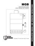
SERIES 15B CAST iRON GAS FIRED BOILERS
FOR FORCED HOT WATER
MODEL NUMBERS:
15045,15070,15096,
15120,15145,15175,
15195,15245,15295
PENNCO BOILERS
85 Middle Rd.
Dunkirk. NY 14048
Ph: (7161 366-5500
Fax: (7161 366-1209
www. ecrinternational.com
R International
An/SO
Brand
Ic_/
9001-2000 Certified Company
F N 1305026, Rev. 1.1 [03/05]
P/N# 1305026,
Rev 1 1 [03/05]
• Printed
in USA.
MPORTANT:
OMPLETELY
Safety Symbols and Warnings
Ratings and Data
Installation Procedure
Ventilation and Combustion Air
Connecting Supply
Vent Installation
Vent System
and Return Piping
8
10
Modification
and Instructions
mstructlon_
1. Keep boilerarea
clear and free from combustible materials,
gasoline and other flammable
vapors and liquids.
Instructions
11
12
12
12
2. DO NOT obstruct
room.
15
of factory
equipped,
supplied
or specified
components
may result in property damage,
Normal Sequence of Operation
General Instructions
17
18
Checking Gas Input Rate to Boiler
Boiler Exploded View
Replacement
Parts Lists
Conversion Kits
20
21
22
27
,
Read the following
before mstalhngll
10
Vent Damper Installation
Connecting Gas Service
Electrical Wiring
Thermostat Installation
Lighting
3
4
5
6
Made In USA
KEEP THIS
BOILER
RETAIN
FORMANUAL
FUTURE NEAR
REFERENCE
3. Modification,
personal
air openings
substitution
to the boiler
or elimination
injury or the loss of life.
4. TO THE OWNER
- Installation
of this boiler
fied installer.
be performed
must
and service
by a quali-
5. TO THE INSTALLER
- Leave all instructions
with the boiler for future reference.
)
6. When this product is installed in the Corn=
monwealth
of Massachusetts
the installation
must
The following defined symbols are used throughout
this manual to notify the reader of potential hazards
of varying risk levels
nediCates an imminently
hich,
if not avoided,
dicates
hazardous
WiLL
a potentially
hich, if not avoided,
serious injury,
k,Licensed
situation_
result in death or I
hazardous
COULD
result
situation
I
in death
I
practices,
Plumber
or
J
boilers and venting should
a qualified
expert
and in
the appropriate
Pennco
or venting
a boiler or any
other gas appliance
with improper methods
or materials
may result in serious
injury
or
death due to fire or to asphyxiation
from
poisonous
gases such as carbon monoxide
which is odorless and invisible.
_J
j
dicates
a potential
hazardous
situation
I
hich, if not avoided,
MAY result in minor or I
oderate injury. It may also be used to alert I
unsafe
by a Licensed
Gas Fitter.
All installations
of
be done only by
accordance
with
manual.
Installing
i
gainst
be performed
j)
(if
_"
C S A
For
Natural
,,_
,,
Certified
Gas
Or Propane
o¢®@
Tested
For
100 LBS
ASME
/_,,orkln g Pressure
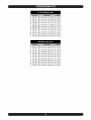
15045
45,000
37,000
32,000
243
1
15
30
47
2.4
82%
80%
15070
70,000
57,000
50,000
365
2
15
33
50
4.0
82%
80%
47
4.0
82%
80%
15096
96,000
79,000
69,000
481
2
30
30
15120
120,000
98,000
85,000
603
3
30
31
49
5.6
82%
80%
47
5.6
82%
80%
15145
145,000
119,000
I03,000
7t9
3
30
30
15175
175,000
141,000
I23,000
829
4
30
31
49
7.2
80.5%
80%
15195
195,000
157,000
137,000
957
4
30
30
47
7.2
80.5%
80%
15245
245,000
197,000
171,000
1,t89
5
30
30
47
8.8
80.5%
80%
15295
295,000
237,000
206,000
1,368
6
60
30
47
I0.4
80.5%
80%
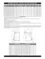
HAll boilers are design certified for installation on noncombustible
--For installation on combustible floors use combustible floor kit
floor.
--Recommended
chimney height 20 feet In special cases where conditions permit, chimney height may be reduced to 10 feet Refer to the latest revision of
NFGC part 11.
--Electric service to be 120 Volts, 15 Am ps, 60 Hz
--The MEA number for the this boiler is 39-86-E Vol VIII
§ For elevations above 2000 feet, ratings should be reduced at a rate of 4% for each 1000 feet above sea level
1 Base on 170 ° temperature in radiators
:1:Tank sized for non-ferrous baseboard or radiant panel systems. Increase size for cast iron baseboard and radiation
--Net I=B=R ratings include 15% allowance for normal piping and pick-up load Manufacturer should be consulted on installations having other than normal piping
and pick-up requirements
** For equivalent square feet of radiation, divide I=B=R output by 150.
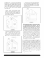
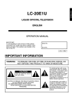
STANDARD
EQUIPMENT:
Boiler Jacket, Cast Iron Boiler Battery, High Limit Control, Vent Damper Relay, Theraltimeter
Gauge, Circulator With Return Piping To Boiler,
Main Gas Burners, Combination 24 Volt Gas Control dnciudes Automatic Gas Valve, Gas Pressure Regulator, Automatic Pilot, Safety Shutoff, Pilot Flow Adjustment, Pilot
Filter), A.S.M.E. Relief Valve, Drain Cock, Spill Switch, Rollout Switch, Automatic Vent Damper Not Shown Are: Wiring Harness, Thermocouple, Nondinting Safety Pilot.
'_D"
OPTIONAL EQUIPMENT: Intermittent Electbc Ignition PHot System.
"A"
25 5/16"
.....
kB" _
"Z'
"C"
4"
.
,1 d
,
.oi
5j
......
-o
i
col
1 ]/4 II REURN
%
1 1/4"
t
U
t
-oi
U
15045
½"
11.250
5.625
4.000
27.125
20.469
4.969
1¼"
15070
½"
15.125
7.562
5.000
28.125
20.969
4.969
1¼"
15096
½"
15.125
7.562
5.000
28.125
20.969
4.969
1¼"
15120
½"
19.000
9.500
6.000
29.125
21.469
5.469
1¼"
15145
½"
19.000
9.500
6.000
29.125
21.469
5.469
1¼"
15175
½"
22.875
11.438
7.000
30.125
21.969
5.969
1¼"
15195
½"
22.875
11.438
7.000
30.125
21.969
5.969
1¼"
15245
¾"
26.750
13.375
8.000
31.125
22.469
6.969
1¼"
15295
¾"
30.625
15.312
9.000
32.125
22.969
8.969
1¼"
* Propane Gas Inlet (All Units) 1/2"
1. The installation must conform to the requirements
of the authority having jurisdiction or, in the absence
of such requirements,
to the latest revision of the
National Fuel Gas Code, ANSI Z223. (Available from
the American
Gas Association,
8501 E. Pleasant
Valley Road, Cleveland,
Ohio 44134). Reference
should also be made to local gas utility regulations
and other codes in effect in the area in which the
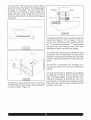
7. Allow 24 inches at the front and right side for
servicing and cleaning.
8. When installed in a utility room, the door shoutd be
wide enough to allow the largest boiler part to enter,
or to permit replacement of another appliance such
as a water heater.
installation is to be made. When installed in Canada:
The latest revision of the CAN 1-B 149.1 and/or B 149.2
9. FOR INSTALLATION
ON NON-COMBUSTIBLE
FLOORS ONLY - For installation on combustible
Installation Codes for Gas-Burning
local codes.
flooring special base part no. 325-2-8.00 must be
used. The boiler can not be installed on carpeting.
Minimum
clearances
to combustible
construction
2. Where required bythe authority
Equipment
and/or
having jurisdiction,
the installation must conform to American Society
of Mechanical Engineers Safety Code for Controls
and Safety Devices ForAutomaticatly
Fired Boilers,
ANSI/ASME
No.CSD-1.
3. This boiler series is classified as a Category 1 and
the vent installation shall be in accordance with Part
7 of the National Fuel Gas Code noted above when
installed in the United States.
In Canada refer to
the CAN1-B149.1
and or B149.2 Installation Codes
for Gas-Burning
provisions
Equipment.
are:
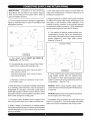
TOP ...................................................
18 IN.
FRONT ......................................
ALCOVE *
FLUE CONNECTOR
........................... 6 IN.
REAR ...................................................
CONTROL SIDE ..................................
OTHER SIDE .......................................
NOTE:
supersede
Greater
clearances
fire protection
for
access
8 IN.
9 IN.
3 IN.
should
clearances.
Also refer to applicable
of the local building
codes.
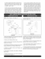
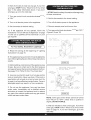
* The definition of an Alcove is a three sided space with
no wall in front of the boiler. TheANSI standard for an
4. This boiler has met safe lighting and other
performance criteria with the gas manifold and control
alcove is 18 inches from the front of an appliance to
the leading edge of the side walls as shown below.
assembly on the boiler per the latest revision of ANSI
Z21.13/CGA 4.9.
5. The boiler shall be installed such that the gas
ignition system components
are protected
from
MINIMUM CLEARANCES TO COMBUSTIBLE CONSTRUCTION (AS SEEN FROM ABOVE)
water(dripping,
spraying, rain, etc.)during appliance
operation
and service,
(circulator
replacement,
condensate trap, control replacement,
etc.).
6. Locate
boiler on level, solid
base
as near the
chimney as possible and centrally located with respect
to the heat distribution system as practical.
_
9"_
3"
18"
1
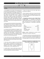
COMBUSTION
(Minimum
ANSI Z223.1 section 1.7), the boiler area
should be considered as a confined space.
In this case air for combustion and ventilation
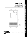
AIR REQUIREMENTS
Square Inches Requirement)
shall be provided according to Step 5. If there
is any doubt, install air supply provisions in
accordance
with the latest revision of the
National Fuel Gas Code.
i iii,ii!o iiiB
15045
I00
10
I3
25
15070
I00
15
I9
38
15096
I00
20
25
50
15120
I25
25
32
63
15145
I50
30
38
75
15175
I75
35
44
88
15195
200
40
50
I00
15245
250
50
63
I25
15295
300
60
75
150
3. When a boiler is installed
space
in a building
of unusually
tight
construction,
air for combustion
and
ventilation must be obtained from outdoors
* A space whose volume is not less than 50 cubic feet per 1000 BTU per hour of all
appliances installed in that space (cubic feet of space = height x width x length)
** A space whose volume is less than 50 cubic feet per 1000 BTU per hour of a!t
appliances installed in that space (cubic feet of space = height x width x length)
1. Ventilation of the boiler room must be adequate to
provide sufficient air to properly support combustion
per the latest revision of the National Fuel Gas Code,
ANSI Z223.1 section 5.3.
i
c,R
i3
I FIGURE 1 !
2. When a boiler is located in an unconfined space in a
building or conventional construction frame, masonry
or metal building, infiltration normally is adequate to
provide air for combustion and ventilation. However,
if the equipment is located in a building of unusually
tight construction (See the National Fuel Gas Code,
in an unconfined
or from spaces freely communicating
with the
outdoors. A permanent opening or openings
having a total free area of not less than 1
square inch per 5000 BTU per hour of total
input rating of all appliances shall be provided.
Ducts may be used to convey makeup air
from the outdoors and shall have the same
cross-sectional
area of the openings
they are connected.
4. When
air for combustion
and ventilation
to which
is from
inside buildings, the confined space shall be provided
with two permanent openings, one starting 12 inches
from the top and one 12 inches from the bottom of the
enclosed space. Each opening shall have a minimum
free area of I square inch per 1000 BTU per hour of
the total input rating of all appliances in the enclosed
space, but must not be less than 100 square inches.
These openings must freely communicate
directly
with other spaces of sufficient volume so that the
combined volume of all spaces meets the criteria
for an unconfined space. (Figure 1)
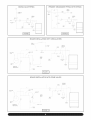
5. When the boiler is installed in a confined space
and all air is provided from the outdoors the confined
space shall be provided with one or two permanent
openings according to methods A or B. When ducts
are used, they shall be of the same cross sectional
area as the free area of the area of the openings
to which they connect. The minimum dimension of
rectangular
air ducts shall be not less than 3 x 3
inches or 9 square inches.
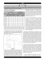
A. When
commence
installing
within
two openings,
one
must
12 inches from the top and
the other within
12 inches from the bottom
of
the enclosure. The openings shall communicate
directly, or by ducts, with the outdoors or spaces
(crawl or attic) that freely communicate with the
outdoors. One of the following methods must
be used to provide
and combustion.
adequate
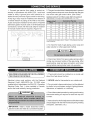
3. If horizontal ducts are used, each opening
and duct shall have a minimum free area 1
square inch per 2,000 BTU per hour of total
input rating of all appliances in the enclosed
space. (Figure 4)
air for ventilation
CHIMNEY
OR
VENT
GAS
1. When directly communicating
with the
outdoors, each opening shall have a minimum
free area of 1 square inch per 4,000 BTU per
hour of total input rating of all equipment
the enclosure. (Figure 2)
in
CH MNEY
VENTLAT ON LOUVERS
i
(EACH ENDQF ATTIC:}
OUTLET/
•
y"
i_ii
".......
ii ii
i!i}!}i}i}iE
J}i:}iii!iiiiii}
!iiiiiiii
¸:}i!}i}i}i}i:}ii{
¸i¸i!!i¸ii! iiii!i!!iiiiiE!i}
iiik
fi!¸U}:}i!}:::i
!
J
AIR
VENT FIPE
...............
VENTLATIOn
LOUVEnS
Fort
\
IFGORE21
2. When communicating
with the outdoors by
means of vertical ducts, each opening shall
have a minimum free area of 1 square inch per
4,000 BTU per hour of total input rating of all
appliances in the enclosed space. (Figure 3)
VFNT
(EACH
LAT ON
END
LOUVERS
OF
ATTIC}
....
CHIMNEY
B. One permanent opening, commencing within
12 inches of the top of the enclosure, shall be
permitted where the equipment has clearances
of at least 1 inch from the sides, 1 inch from the
back, and 6 inches from the front of the boiler.
The opening shall directly communicate
with
the outdoors or shall communicate
through a
vertical or horizontal duct to the outdoors or
spaces (crawl or attic) that freely communicate
with the outdoors.
The openings must have a
minimum free area of I square inch per 3000 Btu
per hour of the total input rating of all equipment
located in the enclosure.
The free area must
be no less than the sum of the areas of all vent
connectors
in the confined
space.
6. In calculating free area using louvers, grilles or
screens for the above, consideration
shall be given
to their blocking effect. Screens used shall not be
smatter than 1/4 inch mesh. If the free area through
a design of louver or grill is known, it should be used
in calculating the size opening required to provide
the free area specified. If the design and free area
is not known, it may be assumed that wood louvers
will have 20-25% free area and metal louvers and
[]ZI }
i IZ] _ZZZIiZiZZZI i IZ] IZZZI LZI i !
grilles will have 60-75% free area. Louvers and grilles
should be fixed in the open position or interlocked
with the boiler so they are opened automatically
during the boiler operation.
MPORTANT:
Circulators
in the
foltowing"_
tustrations are mounted on the system supply I
ide, but mounting on the system return side is I
!soaccep!ab!e
p! e:
)
1. Connect supply and return piping as suggested in
Figure 5 when the boiler is used in connection with
refrigerated systems•
P_ESSU_E
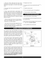
6. Bypass piping is an option which gives the ability
to adjust the supply boiler water temperature
to fit
the system or the condition of the installation• This
method of piping, however, is not typically required
for baseboard heating systems• Typical installations
where bypass piping is used are as follows:
/ VALVE
G_TE
,,VALVE
A. This method is used to protect boilers from
condensation
forming due to low temperature
return water• Generally noticed in large converted
gravity systems or other large water volume
systems• (Figure 6)
i
:E:
vA,_ ,
_'_tE
5. Hot water boilers and system must be filled with
water and maintained to a minimum pressure of 12
pounds per square inch.
E
_SCN
,,_TE
BYPASS PIPING
suPP
........
' :i_ii
_ESSU_E
,'_V,kp,'E
.... :ii
FIGURE 5 I
....
::.
A. The chilled medium MUST
PARALLEL
with the boiler•
BE PIPED
- During cooling cycle, open valves C and D,
close valves A and B.
clearance
of one inch
to hot water pipes•
2. When the boiler is connected to heating coils located
in air handling units where they may be exposed to
refrigerated air circulation, the boiler piping system
MUST BE supplied with flow control valves or other
automatic means to prevent gravity circulation of the
boiler water during the cooling cycle.
3. Hot water boilers
must be provided
installed
above
,
B
_ALTE
- During heating cycle open valves A and B,
close valves C and D.
a minimum
::
IN
B. Use appropriate valves to prevent the chilled
medium from entering the heating boiler•
C. Maintain
,
radiation
level
with a low water cut-off device•
4. When a boiler is connected to a heating system
that utilizes multiple zoned circulators, each circulator
must be supplied with a flow control valve to prevent
gravity circulation•
C
_
PUROE
V_LVE
IF'GURE01
B. These methods are used to protect systems
using radiant panels and the material they
are encased in from high temperature
supply
water from the boiler and protect the boiler from
condensation.
(Figures 7-8)
NOTE#l:
When using bypass piping, adjust
vatvesAand
B until desired system temperature
is obtained•
NOTE#2: Bypass loop must be same size piping
as the supply and return piping.
7. Installation using circulators and zone valves are
shown in Figures 9-10. Forfurther piping information
refer to the I=B=R Installation and Piping Guide•
MIXING VALVE PIPING
PRIMARY SECONDARY PIPING WITH BYPASS
FL
M_x
_
TE_IPERATURE
a£uaE
C_RCU_£TC,_
_LC,W
V£LVE
S,STEr4
, T=_,IPE_£TURE
S,sUC_=
_,
S_ST_4
=r,ESSURE
_EDU,S,r_a
"/AL_'E
,_LVE
O_E
_L,'E
GATE
,h,ALVE
4;
P ESSdRE
R_DUO O
VA:,
-.
i
,_L',
PURaE
V£LVE
_1
PURGE
[ FIGURE 7]
FIGURE 8 ]
BOILER INSTALLATION WITH CIRCULATORS
>
i
FLO'A
CONTRC L
/_L FS
:4:#.
HOT
(OLD
INLET
¢_/_TER
OJTLET
%ATER
T/_NK
PRESSiJRL
REDdCING
/VALVE
GATe
/VALVE
CR
x
S_STEM
RETgRN
PrPiNG
FEED
,',ATER
ilia'ZZZZZ£
THER /_L
TR/_p
qRING FOR
THER; O TAT
Pur!P "_O TROL
pL_iRC_E
]
RELEF VALVE
PURG
V_LvE
t FIGURE 9 J
BOILER INSTALLATION WITH ZONE VALVES
PRcSSiJRE
REDUCING
/VALVE
GATe
/VALVE
COLD W_TER
INLET
HOT CATER
OUTLET
C:_R
T_NK
,!
ZONE
,_L'E
/
CHECK
S_'3TEM
RETdRN
VALVE
[ \
/
PIPING
FEED
(,_TER
f\
EXDA
51ON
TANK
ill
THERMAL
TR#P
PURGE
ALE
CRNG FOR
THERMOSTAT /
PUMP CONTROL
RELIEF
/_L,E
PURGE
'/_L'
E
FIGURE I0]
,_
II installations of boilers and venting should be done only by a qualified expert and in accordance
ith the appropriate Utica Boilers manual. Installing or venting a boiler or any other gas appliance
ith improper methods or materials may result in serious injury or death due to fire otto asphyxiation
om poisonous
his boiler
_positive
shall
gases such as carbon
not be connected
monoxide
to any portion
with is odorless
and invisible.
of a mechanical
draft system
J
operating
und
pressure.
1 The vent pipe must slope upward from the boiler
not less then I/4 inch for every 1 foot to the vent
terminal
shall be Type B or metal pipe having resistance to
heat and corrosion not less than that of galvanized
sheet steel or aluminum not less than 0 016 inch
thick (No 28 Ga)
2 Horizontal portions of the venting system shall
be supported rigidly every 5 feet and at the elbows
No portion of the vent pipe should have any dips
or sags
3 This boiler series is classified as a Category 1
and the vent mstallahon shall be m accordance with
chapter 7 and 10 of the Nahonal Fuel Gas Code
noted above or apphcable provisions of the local
building codes
4 Inspect chimney to make certain it is constructed
according to NFPA 211 The vent or vent collector
5 Connect flue pipe from draft hood to chimney
Bolt or screw joints together to avoid sags Flue pipe
should not extend beyond reside wall of chimney
Do not install manual damper in flue pipe or reduce
size of flue outlet except as prowded by the latest
rewslon ofANSIZ223
1 Protect combustible celhng
and walls near flue pipe with fireproof insulation
Where two or more apphances vent into a common
flue, the area of the common flue must be at least
equal to the area of the largest flue plus 50 percent
of the area of each additional flue
When an existing boiler is removed from a common
venting system, the system is hkely to be too large
is no blockage or restriction, leakage, corrosion
and other deficiencies
which could cause an
for the proper venting of the apphances still connected to it If this situation occurs, the following test
procedure must be followed
unsafe condition
At the time of removal of an existing boiler, the following steps shall be followed with each appliance
remaining connected tothe common venting system
placed m operation, while the other apphances remaining connected to the common venting system
are not in operation
A
Seal an unused
opening
in the common
venting system
B Visually mspectthe venting system for proper
size and horizontal pitch and determine there
C Insofar as is practical, close all building doors
and windows and all doors between the space
in which the appliances
remaining connected
to the common venting system are located and
other spaces of the building Turn on clothes
dryers and any other apphance not connected
tothe common venting system Turn on any exhaust fans, such as range hoods and bathroom
exhausts, so they operate at maximum speed
Do not operate a summer
fireplace dampers
D Place
in operation
exhaust
the apphance
fan
Close
being re-
spected Follow the hghtmg mstruchons Adjust
thermostat
so apphance will operate continuously
E. Test for spitlage atthe draft hood retief opening
after 5 minutes of main burner operation. Use
the flame of a match or candle, or smoke from
G. Any improper operation of the common venting system should be corrected so the installation
conforms with the latest revision of the National
a cigarette,
Fuel Gas Code, ANSI Z223.1. When resizing
any portion of the common venting system, the
cigar or pipe.
F. After it has been determined that each appliance remaining connected to a common venting
system properly vents when tested as outlined
above, return doors, windows,
exhaust fans,
fireplace dampers and any other gas burning
appliances to their previous condition of use.
NOTE:
Refer to Figure 11 for steps 1-7.
common venting system should be resized to
approach the minimum size as determined using the appropriate tables in appendix G in the
latest revision of the National Fuel Gas Code,
ANSI Z223.
1. Ensure that only the boiler is serviced
Damper. (Figure 12)
!NSTALL R
HOOK JP
LJIX #C:C:EPT,_
E)#I
by the Vent
BLE
PER LOC#T
ONS
DAMPR
,MOTOR
•
VENT
DAM_'ER
VENT
OI.TLET
CONTROL
VENT DAMPER
INSTALL R
OOK
U?
/"
HAR
ESS
HOT d'/ATER HEATER
H! LIM,F
CONTROL
_'_
FACTORY
IFIGURE
WRD
121
I FIGURE 111
2. Clearance
1. Place Vent Damper
of boiler as possible.
on or as close to vent outlet
(Figure
12)
service
2. Remove
Vent Damper
3. Remove
Iocknut from connector
of not less than 6 inches between
of Vent Damper.
Motor cover.
3. Vent Damper
Damper
Vent
Damper and combustible
material must be maintained. Additional clearance should be allowed for
at the end of the
appliance
must be in the open position when
main burners
are operating.
wire harness.
4. Feed Damper and Damperwire harness connectors
through bracket hole on Damper Motor frame.
5. Replace and tighten
harness connector.
6. Plug Damper
Motor frame.
Iocknut
connector
onto Damper
wire
4. The Vent Damper position indicator
visible location following installation.
5. The thermostat's heat anticipator must be adjusted
to match the total current draw of all controls associated with the boiler during a heating
into socket
on Damper
7. Replace Damper Motor cover and wire Damper
in accordance with Figure 11.
must be in a
cycle.
1. Connectgas servicefrom meter to control assemblyin accordancewith ANSIZ223.1 and local
codesor utility.A groundjoint unionshould be installedforeasyremovalofgas controlforservicing.
A dripleg or trap mustbe installedat the bottomof
a verticalsectionof pipingat the inletto the boiler.
A pipe compoundresistantto the actionof liquified
petroleumgasesmustbe usedon allthreadedpipe
connections.Checkwith the localutilityfor location
of manualshutoffvalveif required.(Figure 13)
INS
IALL
6
#_.
b
£t
_/'FIE_E
MANUAL
VALVE
(183cm)
(]5_crn)
REOUIRED
EJ]F
FH_
AB_VE
BY
%,/2/
HIM
BOILER
Z_ND
T,_
FL NrqR
LEI]CAL
CE]DE3
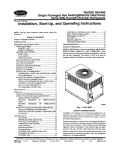
2. The gas line should be of adequate size to prevent
undue pressure drop and neversmalter
than the pipe
size of the main gas control valve.
MAXIMUM CAPACITY
(See Chart)
OF PiPE IN CUBIC FEET OF GAS/HOUR
(Gas Pressure = 0.5 psig or less, Pressure Drop = 5 in. w/c)
I0
175
360
680
1400
20
120
250
465
950
30
97
200
375
770
40
82
170
320
660
60
66
138
260
530
80
57
118
220
460
100
50
195
400
Foradditionalinformation
Code Handbook.
I03
referto"Table
C"ofthe
National Fuel Gas
3. To check for leaks in gas piping, use a soap and
water solution or other approved method.
.3"
_---
GAS
(8
c_,)
MINUMUM
LEG
DRIP
CDNTRD
ZNi
ET
[Fl U .Sq
4. Disconnect boiler from gas supply piping system
during any pressure testing of the gas piping. After
reconnecting,
leak test gas connection and boiler
piping before placing boiler back into operation.
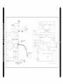
SEE WIRING DIAGRAMS
WO PAGES
ON THE FOLLOWING_
FOR DETAILS.
j/
1. Thermostat should be installed
about four feet above the floor.
Electrical wiring must conform with the National
Electrical
Code, ANSI/NFPA
No. 70-1990 when
installed in the United states, the CSAC22.1 Canadian
Electrical Code, Part 1, when installed in Canada
2. NEVER
and/or the local authority
televisions,
having jurisdiction.
install a thermostat
3. Do not install a thermostat
on an outside wall.
where it witl be affected
by drafts, hot or cold pipes, sunlight,
a fireplace,
on an inside wall
lighting fixtures,
or a chimney.
4. Check thermostat operation by raising and lowering
thermostat setting as required to start and stop the
burners.
_h
IMPORTANT:
Lbetween
Install
a fused disconnect
boiler and meter at a convenient
switch h
location S
5. Instructions for the final adjustment of the thermostat
are packaged with the thermostat (adjusting heating
anticipator, calibration, etc.)
HONEYWELL
L4080B
THERMOSTAT
L7
]
--1_
TR
r J
vtA E
I
I
I
I
I
I
I
0
I
I
CAMPER
BOARD
CONTROL
NEUTRAL
115 VAC
POWER
SUPPLY
HOT
OVER CURRENT & PROTECTED
DESCONNECT
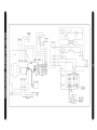
HONEYWELL
L4OSOB
THERMOSTAT
_
LB/C2
_>_Pv
C1
_
LI
1 V_aR2°4
TR
1
L]'_]rJ
I1_
O
ssw
vR°3°°
--4<
--X<
<4
--<4
RSW
L
I
I
TH--2
IK
b
L
I
I
I
I
I
I
J
IL
L_b__
I
I
FUSE
_oo.
11234
I
__
]
S8600(F,M)
INTERMITTENT
PILOT CONTROL
RSX4
SSb4
s
6
9 I
RToT_I_K
T_T
IBK _09_TO
PILOT
NEUTRAL POWER
115 VAC
HOT
SUPPLY
OVER CURRENT & PROTECTED
DISCONNECT
| | J w l_
wl,u:
J
GAS VALVE
|
PvJMv
IZ'_
VRB204A
_
_
VR8304M
/
B
push in or turn by hand, don't try to repair it. Call
a qualified service technician. Force or attempted
repair may result in a fire or explosion.
D. Do not use this appliance
if any part has been
under water. Immediately
call a qualified service
technician to inspect the appliance and to replace
any part of the control system and any gas control
which has been under water.
1. STOP! Read the safety information
information Manual.
For Your Safety,
Read Before
in the User's
Operating!!
A. This appliance is equipped with an ignition device
which automatically
lights the pilot. Do not try to light
the appliance by hand.
2. Set the thermostat
to lowest setting.
3. Turn off all electric
power to the appliance.
4. This appliance
B. Before operating, smell all around the appliance
area for gas. Be sure to smell next to the floor
because some gas is heavier than air and will settle
on the floor.
is equipped
with an ignition device
which automatically
lights the pilot. Do not try to light
the pilot by hand. (Figure 14)
(i:/_
_
iN[
INLI
[
F RE
:-"
S?UI_E
JA CAUT,O.
WHAT
TO DO IF YOU SMELL
GAS
* Do not try to light any appliance.
* Do not touch any electrical switches;
use any phones in your building.
* Immediately
call your gas supplier
neighbor's
phone.
instructions.
Follow
do not
from
a
the gas supplier's
G F'_._
I]LJ
* If you cannot reach
the fire department.
your
gas supplier,
I
I2 I
call
C. Use only your hand to push in or turn the gas
control knob. Never use tools. If the knob wilt not
6. Turn
"OFF."
gas
control
knob
clockwise_
to
6. Wait (5) minutes to clear out any gas. If you then
smell gas, STOP! Follow "What To Do If You Smell
Gas" in the safety information
above. If you don't
smell gas, go on to the next step.
7. Turn gas control
to "ON."
8. Turn on all electric
9. Set thermostat
10. If the
at the beginning
knob counterctockwisef-'_,,
power to the appliance.
to desired
appliance
1. STOP! Read the safety information
of these instructions.
wilt
to the lowest setting.
3. Turn off all electric
power to the appliance.
4. Remove
setting.
not operate,
2. Set the thermostat
follow
instructions "To Turn Off Gas To Appliance"
13 and call a qualified service technician
the
on page
or your
access panel and burner door.
5. Turn gas control knob clockwise
(Figures
i_to
"OFF."
15 and 16)
gas supplier.
A. Read the warning at the beginning
Instructions" on page 15.
of "Lighting
/i//
B. This appliance has a pilot which must be lighted by
hand. When lighting the pilot, follow these instructions
exactly.
FIGURE t5]
C. Before lighting, smell all around the appliance area
for gas. Be sure to smell next to the floor because
some gas is heavier than air and will settle on the floor.
See page 15 for "What To Do If You Smell Gas."
PRESSURE
RE@ULATOR
INLET
PRESSURE
OUTLET
PRESSURE
TAP\
TAP
D. Use only your hand to push in or turn gas control
knob or reset button. Never use tools. If the knob or
reset button will not push in or turn by hand, don't try
to repair it, call a qualified service technician. Force or
attempted repair may result in a fire or explosion.
E. Do not use this appliance if any part has been
under water. Immediately
call a qualified service
technician to inspect the appliance and to replace
any part of the control system
which has been under water.
and any gas control
GA£
NUT
GAS
INLET
PILOT
BENEATH
@AS
CONTROL
FLOW
ADS
COVER
FT
SCREW
SCRE%J
KNOB
IFIGURE
161
NOTE: Some gas control knobs cannot be turned
from "PILOT" to "OFF" unless knob is pushed in
slightly. DO NOT FORCE,
6. Wait (5) minutes to clear out any gas. If you then
smell gas, STOP! Follow "What To Do IfYou Smell
Gas" on page 15. If you don't smell gas, go to the
next step.
7. Find pilot. Follow metal tube from gas control.
Dependingon the modelof the boiler,pilotis either
mounted on the base or on one of the burner
tubes.
8. Turn gas control knob counterclockwise
to "PILOT."
f'_'_,
10. Replace
burner door.
11. Turn gas control knob counterclockwise
to "ON."
12. Replace
access panel.
13. Turn on all electric
9. Push
in gas control
knob or reset button
power to the appliance.
if so
equipped, all the way in and hold. Immediately light
the pilot with a match. Continue to hold the gas control
knob or reset button in for about 1 minute after the
pilot is lit. Release
14. Set thermostat
to desired
setting.
knob or button, and it will pop up
back up. Pilot should remain lit. If it goes out, repeat
steps 5 through 9.
* If knob or button does not pop u p when released,
stop and immediately
call a qualified service
technician or your gas supplier.
1. Set the thermostat
to lowest setting.
2. Turn offatl electric power to the appliance
is to be performed.
the gas control knob clockwise
,_'_tto
"OFF."
See note on page 16 and call a qualified
technician or your gas supplier.
heat, the
thermostat
will
and damper
the damper.
the ignition
4. Call a qualified
service
technician.
service
actuate,
completing the circuit to the control. The completed
circuit to the control will first activate the circulator
FOR h,/O DE L3:
15045 THROUGH 1509_
FOR MODELS:
i5123 THRCL, GH 15275
"\
which will close an end switch inside
This action will complete the circuit to
"\\BLOCKED
VENT
5A_EIY 5WIICd
system and ignition wilt take place.
INTEGR/\L
H ( ):1[
In the event the boiler water temperature
exceeds
the high limit setting on the boiler mounted high
limit control, power will be interrupted between the
control system and the ignition system. The power
will remain off until the boiler water temperature
drops below the high limit setting. The circulator wilt
continue to operate under this condition until the
thermostat is satisfied.
D R/_ FT /
_
BASE.
FOR MODELS: 150 8 & 152P5
//
\.
"\MAN
IACKET
main burner gas off. (Figure 17) If either of these
conditions occur, DO NOT ATTEMPT TO PLACE
THE BOILER BACK INTO OPERATION. CONTACT
A QUALIFIED
SERVICE
AGENCY.
FCLD
ROLL OdT 3A_ ETI'j /
SWITCH
BAS
PANEL
IFIGURE
In the event the flow of combustion products through
the boiler venting system becomes blocked, the
blocked vent safety switch will shut the main burner
gas off. Similarly,
if the boiler flueway becomes
blocked, a flame rollout safety switch will shut the
if service
3. Push in gas control knob slightly and turn clockwise
_to
"OFF." DO NOT FORCE.
* If the pilot will not stay lit after several tries, turn
On a call for
f_"_'\
171
Before seasonal
start-up,
have a competent
service
The venting system should be inspected
agency check the boiler for soot and scale in the
flues, clean the burners and check the gas input rate
to maintain high operating efficiency.
of each heating season. Check the vent pipe from
the boiler to the chimney for signs of deterioration by
rust or sagging joints. Repair if necessary. Remove
the vent pipe at the base of the chimney or flue and
using a mirror, check vent for obstruction and make
iAc o,,o.Ai
certain the vent is in good working
abel all wires prior to disconnection
when
ervicing
controls.
Wiring errors
can cause
proper
and dangerous
Verify proper operation
I
I
operation.
after service.
The service agency or owner should make certain
the system is filled with water to minimum pressure
and open air vents, if used, to expel any air that may
have accumulated
in the system. Check the entire
piping system
repaired.
and, if any leaks appear,
Many circulators
require periodic
at the start
order.
The boiler flue gas passageways
may be inspected
by a light and mirror. Remove the burnerdoor. (Figure
17) Place a trouble lamp in the flue collector through
the draft relief opening. With the mirror positioned
above the burners, the flue gas passageways
be checked for soot or scale.
can
The following procedure should be followed to clean
the flue gas passageways:
have them
1. Remove
like the one pictured in Figure 18
servicing. The motor usually has
openings at each end to lubricate the bearings.
Put about one half teaspoon of SAE 20 or 30 nondetergent motor oil in each opening twice a year.
the burners
from the combustion
chamber by raising the burners up from the
manifold orifices and pulling toward the front of
the boiler. (Figure 17)
2. Disconnect
hood.
the
vent
pipe
3. Remove
the top jacket
4. Remove
the combination
from
the
draft
flue collector
and
panel.
draft hood from the boiler castings by loosening
the nuts on the hold down bolts located on each
side of the collector.
(Figure
17)
5. Place a sheet of heavy paper or similar
material over the bottom of the base and brush
down the flue passageways.
The soot and scale
will collect on the paper and is easily removed
with the paper.
With the paper still in place in the base, clean
the top of the boiler castings of the boiler putty
or silicone used to seal between the castings
FIGURE 18J
Do Not Over
and flue collector. Make certain that chips are
not lodged in the flue passageways.
Oil!!
Many circulators have an oil opening for the shaft
bearing. This should be oiled at the same time for quiet
When the cleaning
boiler components
operation. Follow the manufacturer's
oiling the shaft bearing.
boiler putty or IS-808 GE silicone (available from a
Pennco distributor) to seal around the flue collector
and boiler castings.
instructions
for
process is complete, restore the
to their original position. Use
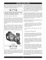
A visual checkof the mainburnerand pilotflames
shouldbe madeat the start of the heatingseason
and again in mid-season.The main burner flame
shouldhavea weltdefinedinnerblue mantelwith a
lighterblue outermantel,Checkthe burnerthroats
andbumerorificesforlintordustobstruction.(Figures
19 and 20)
PZLOT
LIGHT
BLUE
OUTER
MAKN
FLAME
:BURNER
/
MANTEL
FIGURE I8]
To adjust the pitot flame, remove the pilot adjustment
cover screw (Figures 14-16 on pages 15-16) and
turn the inner adjustment
screw counterclockwise
f_'_
to increase or clockwise _"_
to decrease
pilot flame,
FIGURE 19]
adjustment
Be sure to replace
to prevent
possible
cover screw
after
gas leakage,
The burners and pilot should be checked for signs
of corrosion, rust or scale buildup. The area around
the boiler must be kept clear and free of combustible
materials, gasoline and other flammabte vapors and
\
liquids.
The free flow of combustion
and ventilating air to
the boiler and boiler room must not be restricted or
blocked,
iFIGURE
20]
The pilot flame should envelop _8 to ½ inch of the tip
of the pilot thermocoupte,
ignition/sensing
electrode
or mercury sensor, (Figure 21)
It is recommended
that a qualified service agency
be employed to make an annual inspection of the
boiler and heating system, They are experienced
in
making the inspections outlined above, and, in the
event repairs or corrections
are necessary, trained
technicians can make the proper changes for safe
operation of the boiler,
Gas input to the boiler can be adjusted by removing the
protective cap on the pressure regulator (Figures 1416 on pages 15-16) and turning the screw clockwise
_"_to
f-'_'-,
increase
to decrease
input
input.
and
counterclockwise
Natural
gas
manifold
pressure should be set at approximately
3.5 inches
water column. Propane gas manifold pressure should
be set at approximately
11 inches water column.
These manifold pressures are taken at the outlet
side of the gas valve. (Figures 15 and 17 on pages
16-17) To check for proper flow of natural gas to the
boiler, divide the input rate shown on the rating plate
by the heating value of the gas obtained from the
local gas company. This will determine the number
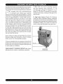
1. Pilot:
pilot gas
With main burner operating,
adjusting
screw
clockwise
control should
main burner.
close, shutting
the boilerwater temperature exceeds the control
temperature
setting, the control will open the
circuit, closing the automatic main gas valve.
Front Lower
Gas Valve
CHECK
SAFETY
adjustments
CONTROL
CIRCUIT
are made for satisfactory
after burner
operation.
off the gas to the
2. High Limit Control
(Figure 22): Remove
cover and note temperature setting. Decrease
this setting to minimum and operate boiler. When
Burner orifices should be changed ifthe final manifold
pressure varies more than plus or minus 0.3 inches
water column from the specified pressure.
air adjustment is not necessary, therefore air
are not furnished as standard equipment.Air
can be furnished on request where required
codes or conditions.
_
until pilot gas is turned off. (Figures 14-16 on
pages 15-16) Within 90 seconds the main gas
of cubic feet of gas required per hour. With all other
gas appliances off, determine the flow of gas through
the meter for two minutes and multiply by 30 to get
the hourly rate. Make minor adjustments to the gas
input as described above.
Primary
shutters
shutters
by local
turn the
I FIGURE 221
I
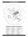
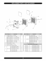
Jacket Front Lower
13
3raft Hood
25
Pipe Nipple
2
Control
14
Restrictor
26
Pilot Spark Control
3
Jacket Front Upper
15
Jacket Back
27
Therattimeter
4
Jacket Side Right
16
Right End Section
28
High Limit Control
5
Left End Section
17
Jacket Side Left
29
Pipe Bushing
6
Push Nipple
18
Relief Valve
30
¢7elt
7
Jacket Top
19
Dipe Nipple
31
Tray
Base
8
Damper
20
_ipe Elbow
32
9
Baffle
21
.Circulator
33
Burner Door
I0
Center Section
22
nipe Nipple
34
Gas Valve
I1
Jacket Back To Flue
23
nipe Tee
35
Manifold
I2
Flue Coltecter
24
3rain Cock
36
Burner Tube
Gauge
\
\
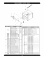
iiii:!i t!!iN:o:iiii:
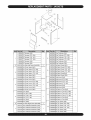
1
3352401
5611601
3urner Tube 1¾" (070, 096)
2
3urner Tube 1¾" (120, 145)
3
3urner Tube 1¾" (175, 195)
4
3urner Tube 1¾" (245)
5
3urner Tube 1¾" (295)
6
6
7
3ase w/Insul & Bracket (045)
3ase w/Insul & Bracket (070, 096)
5611603
3ase w/Insul & Bracket (120, 145)
5611604
3ase w/Insul & Bracket (175, 195)
5611605
3ase w/Insul & Bracket (245)
]611606
3ase w/Insul & Bracket (295)
3261201
3urner Door (045)
32611405
3urner Door (070, 096)
32611401
3urner Door (120, 145)
3
5
1
5611602
2
4
3urner Tube 1¾" (045)
32611402
3urner Door (175, 195)
32611403
3urner Door (245)
32611404
3urner Door (295)
VG-003.05
-gasValve, 24V Nat (045-145)
7G00307
-gasValve, 24V LP (045-295)
7G01101
-gasValve, Spark Nat (045-145)
7G01103
-gasValve, Spark Nat (175-295)
7G01104
-gasValve, Spark LP (045-295)
7G01201
-gasValve, 24V Nat (245, 295)
VG01202
-gasValve, 24V Nat (175, 195)
VG01601
_traight Flange - ¾" NPT (175, 195,
245, 295 - LP ONLY)
8
VG-006.00
Internal Bushing ¾ x ½ (ALL LP)
356-2-1.01
Manifold (045)
356-2-1.02
Manifold (070, 096)
356-2-1.03
Manifold (120, 145)
356-2-1.04
Manifold (175, 195)
356-2-1.05
Manifold (245)
356-2-1.06
Manifold (295)
HW-O05.01
Screw ½- 20 x ½ Self Tap
4
Orifice #30, Nat. (045)
1
Orifice #30, Nat. (096)
2
Orifice #30, Nat. (145)
3
Orifice #30, Nat. (195)
4
Orifice #30, Nat. (245)
5
Orifice #30, Nat. (295)
6
Orifice #31, Nat. (120)
3
Orifice #31, Nat. (175)
4
Orifice #33, Nat. (070)
2
Orifice #47, LP (045)
1
Orifice #47, LP (096)
2
Orifice #47, LP (145)
3
Orifice #47, LP (195)
4
Orifice #47, LP (245)
5
Orifice #47, LP (295)
6
Orifice #49, LP (120)
3
Orifice #49, LP (175)
4
Orifice #50, LP (070)
2
1
355-1-5.01
1
355-1-5.02
355-1-5.03
355-1-5.04
1
355-1-5.06
1
355-1-5.07
/
7/
/
/
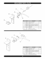
1
HW06901
B - Left Hand Section
1
Tie Rod - ¼" x 7¼" (045)
Push Nipple 2" Mach. (045)
2
Tie Rod - ¼"x 11½" (070,096)
Push Nipple 2" Mach. (070,096)
4
Push Nipple 2" Mach. (120, 145)
6
_lut 5/16-
18 Wislock
14605001
HW-011.01
HW-011.03
Tie Rod - ¼"x 15½" (120, 145)
2
6
7
2
100-2-2.01
43300976
HW-011.05
Tie Rod - ¼"x 19½" (175, 195)
Push Nipple 2" Mach. (175, 195)
8
HW-011.07
Tie Rod - ¼" x 23" (245)
Push Nipple 2" Mach. (245)
10
HW-011.09
Tie Rod - ¼" x 27" (295)
Push Nipple 2" Mach. (295)
12
Baffle (045 Only)
2
3
HW-OO3.O2 _lut ¼"-20 Hex
2
4
HW-OO8.Ol
Nasher - 5/16" Flat
4
5
100-2-3.01
3 - Right Hand Section
1
100-2-7.01
Heat Exchanger
(3 Section)
3 - Center Section (070,096)
1
100-2-7.02
Heat Exchanger
(4 Section)
3 - Center Section (120, 145)
2
100-2-7.03
Heat Exchanger
(5 Section)
3 - Center Section (175, 195)
3
100-2-7.04
Heat Exchanger
(6 Section)
3 - Center Section (245)
4
100-2-7.05
Heat Exchanger
(7 Section)
3 - Center Section (295)
6
100-2-7.06
Heat Exchanger
(2 Section)
100-2-I.01
9
3461601
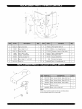
2\
3\
1
2
3
4
5
6
7
1182004
_-"Damper
(045)
34620501
=lue Collector
(045)
1182005
5" Damper
(070,096)
34620502
=lue Collector
(070,096)
34620503
=lue Collector
(120, I45)
34620504
=lue Collector
(175, 195)
1182006
3" Damper
(120, 145)
1182007
7" Damper
(175, 195)
1182008
5" Damper
(245)
34620505
=lue Collector
(245)
1182009
9" Damper
(295)
34620506
=lue Collector
(295)
31623101
Jkt Side Left Panel (046-295)
31623301
Jkt Back Panel (045)
31623001
Jkt Front Upper (045)
31623302
Jkt Back Panel (070,096)
31623002
Jkt Front Upper (070,096)
31623303
Jkt Back Panel (I20,
145)
31623003
Jkt Front Upper (120,
I45)
31623304
Jkt Back Panel (175,
195)
31623004
Jkt Front Upper (175,
I95)
31623305
Jkt Back Panel(245)
31623005
Jkt Front Upper (245)
31623306
Jkt Back Panel (295)
131623006 Jkt Front Upper (295)
34620601
Draft Hood (045)
34620602
Draft Hood (070,096)
34620603
Draft Hood (120,
145)
34620604
Draft Hood (175,
I95)
1
8
1
9
31622001
Jkt Front Lower (045)
31622002
Jkt Front Lower (070, 096)
31622003
Jkt Front Lower (I20,
I45)
31622004
Jkt Front Lower (175,
195)
I
10
I
34620605
Draft Hood (245)
Draft Hood (295)
31622005
Jkt Front Lower (245)
34620606
31622006
Jkt Front Lower (295)
31623501
Jkt Back to Flue (045)
31622701
Tray (045)
31623502
Jkt Back to Flue (070,096)
31622702
Tray (070,096)
31623503
Jkt Back to Flue (120, 145)
31622703
Tray (120,
145)
31623504
Jkt Back to Flue (175, 195)
31622704
Tray (175,
195)
31623505
Jkt Back to Flue (245)
31622705
Tray (245)
31623506
Jkt Back to Flue (295)
31622706
Tray (295)
31622901
Jkt Top Panel (045)
31623201
Jkt Side Right Panel (046-295)
31622902
Jkt Top Panel (070, 096)
3461701
Flue Collector
Restrictor
(045)
31622903
Jkt Top Panel (120, 145)
3461702
Flue Collector
Restrictor
(070)
31622904
Jkt Top Panel (175, 195)
i 3461703
Flue Collector
Restrictor
(096)
31622905
Jkt Top Panel (245)
3461704
Flue Collector
Restrictor
(295)
31622906
Jkt Top Panel (295)
11
I
1
12
I
1
1
1
1
1
\6
I
1520001
I-hermocouple Q309A
I
2
14695046
_crew #8 - I8 x ½
4
2380002
(it, Pilot Tube Assy., Nat. Stdg. 20½"
2380006
iKit, Pilot Tube Assy., LP Stdg. 20½"
4
32621101
Pilot Bracket
1
5
3261401
Pilot Shield
1
6
N/A*
iPtot Tube ¼" x 20½" AL
1
3
1
* Included with #3 - Pilot Tube Assembly Kit (above)
\
\
,\
\
1
PB00702
Pilot Ignition Cable 30"
t
2
14695046
_crews #8 - 18 x ½
2
2380004
iKit, Pilot Tube Assy., Nat. Spark 20½"
2380008
(it, Pilot Tube Assy., LP Spark 20½"
4
32621101
Pilot Bracket
I
5
N!A*
Pilot Tube ¼" x 20½" AL.
1
3
* Included with #3 - Pilot Tube Assembly
Kit (above)
1
13
lO
11
1
AQ-020.01
Welt ¾" x 3"
I
I0
2
AQ-022.01
High Limit Control
I
3
1310001
Pipe - Nipple _A*'x 4"
I
4
VR-001.01
Relief Valve 30#
5
1190001
6
7
8
1310002
Pipe - Nipple 1W' x4½"
9
HW-016.03
1516001
_ipe-Tee1W'x_A'x1W
I1
PB00702
_ilot Ignition Cable 30"
I
I2
375-1-14.01
Wire - Low Voltage/Damper
I
I
I3
37413602
Harness - Ignition to Gas Valve 18"
I
Pipe - Elbow _A*' 90 °
I
I4
37513301
JVire - Roltout/Spilt 28"
2
1260006
Gauge - Theraltimeter
1
15
PB00604
_ilot Spark Control
1
37519501
Harness Circulator 72"
I
I6
EF0360I
:.lamp #3600 White
2
I
I7
Z99
.Control Vent Damper
I
I
I8
240004779
Wire, 2 Cond., Bonded 18"
I
Drain Cock
NPT
'
Base (045 Only)
I
la
32611001
iTemp. Sensor Bracket-
lb
3262001
iTemp. Sensor Bracket - Base (070-295)
I
lc
3461201
iTemp. Sensor Bracket - Flue Collector
I
2
AQ-021.01
2.ontrol - Fixed Temperature Thermostat
Rollout Switch)
1
3
HW06501
Bcrew - #6 x 1/4" Hex HD
2
NOTES:
(1) The rollout switch is located on the base and flue collector•
(2) The quantities above are for each switch.
I
5501270Kit,Conversion
LPtoNatural
5501271Kit,Conversion,
LPtoNaturalI507C
5501272Kit,Conversion,
LPtoNaturalI509C
5501273Kit,Conversion,
LPtoNaturalI512C
5501274Kit,Conversion,
LPtoNatural1514_
5501275Kit,Conversion,
LPtoNatural1517_
5501276Kit, Conversion, LP to Natural I 1519_
5501277Kit, Conversion, LP to Natural I 1524_
5501278Kit, Conversion, LP to Natural ]1529_
5501279
Kit, Conversion
Natural to LP
5501280
Kit, Conversion,
Natural to LP
1507C
5501281
Kit, Conversion,
Natural to LP
1509C
5501282
Kit, Conversion,
Natural to LP
1512C
5501283
Kit, Conversion,
Natural to LP
I514_
5501284
Kit, Conversion,
Natural to LP
I517_
5501285
Kit, Conversion,
Natural to LP
1519_
5501286
Kit, Conversion,
Natural to LP
I524_
5501287
Kit, Conversion,
Natural to LP
I529_