1
48JZ(N) 024-060
Single Packaged Gas Heating/Electric
Heat Pump
Umts With Puron® (R-410A) Refrlqerant
Visit www.camer.eom
Installation, Start-Up, and Operating Instructions
NOTE: Read
installation.
the entire
instruction
TABLE
SAFETY
before
starting
the
OF CONTENTS
CONSIDERATIONS
INTRODUCTION
manual
.....................................................
..........................................................................
1
2
RECEIVING AND INSTALLATION
..........................................
CHECK EQUIPMENT .............................................................
IDENTIFY UNIT ................................................................
INSPECT SHIPMENT ........................................................
2
2
2
2
PROVIDE UNIT SUPPORT ....................................................
ROOF CURB .......................................................................
SLAB MOUNT ...................................................................
2
2
2
GROUND MOUNT ............................................................ 2
FIELD FABRICATE DUCTWORK ........................................ 3
PROVIDE CLEARANCES ...................................................... 4
RIG AND PLACE UNIT ......................................................... 6
CONNECT CONDENSATE DRAIN ...................................... 6
INSTALL FLUE HOOD .......................................................... 6
ELECTRICAL
CONTROLS
AND WIRING
.................. 25
HEAT PUMP SYSTEM ITEMS ......................................
REFRIGERANT
CIRCUIT ...............................................
26
27
GAS INPUT ......................................................................
INDOOR AIRFLOW ........................................................
PURON® SYSTEM ITEMS ............................................
27
27
27
TROUBLESHOOTING
START-UP
CHECKLIST
...............................................................
28
............................................................
28
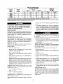
NOTE TO INSTALLER-Before the installation, READ THESE
INSTRUCTIONS
CAREFULLY
AND COMPLETELY.
Also,
make sure the User's Manual and Replacement Guide are left with
the unit after installation.
The furnace is NOT to be used for
temporary
beating
of buildings
or structures
under construction.
INSTALL
GAS PIPING ........................................................... 7
INSTALL DUCT CONNECTIONS ........................................ 9
CONFIGURING
UNITS FOR DOWNFLOW
(VERTICAL) DISCHARGE ............................................................
9
INSTALL ELECTRICAL
CONNECTIONS
......................... I0
HIGH-VOLTAGE
CONNECTIONS
................................
10
SPECIAL PROCEDURES
FOR 208-V OPERATION ...11
CONTROL VOLTAGE CONNECTIONS
....................... 11
HEAT ANTICIPATOR
SETTING ...................................
TRANSFORMER
PROTECTION ....................................
PRE-START-UP
START-UP
CHECK
11
11
..........................................................................
12
...................................................................................
FOR REFRIGERANT
LEAKS ...............................
13
13
START-UP
CHECK
HEAT AND MAKE ADJUSTMENTS
............. 13
HEATING CONTROL .......................................
13
HEATING
SEQUENCE
OF
OPERATION-HEAT
PUMP .................................................................................
18
HEATING
SEQUENCE
OF
OPERATION-GAS
HEAT .................................................................................
18
START-UP COOLING
AND MAKE ADJUSTMENTS.....,
19
COOLING SEQUENCE OF OPERATION ..................... 19
CHECKING
COOLING CONTROL OPERATION
(NONICM UNITS) ......................................................................
19
MAINTENANCE
.........................................................................
AIR FILTER ......................................................................
INDOOR BLOWER AND MOTOR ................................
FLUE GAS PASSAGEWAYS
.........................................
COMBUSTION-AIR
BLOWER .......................................
LIMIT SWITCH ................................................................
BURNER IGNITION ........................................................
MAIN BURNERS .............................................................
OUTDOOR
COIL, INDOOR COIL, AND
CONDENSATE
DRAIN ...................................................
OUTDOOR
FAN ...............................................................
20
22
22
24
24
25
25
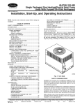
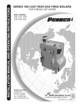
C99O88
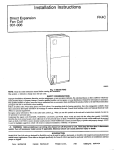
Fig. 1--Untt 48JZ
SAFETY CONSIDERATIONS
Installation and servicing of air-conditioning
equipment can be
hazardous due to system pressure and electrical components, Only
trained and qualified personnel should install, repair, or service
alr-eooditioning
equipment.
Untrained personnel can perform basic maintenance
functions of
cleaning coils and filters. All other operations should be performed
by trained service personnel. When working on air-conditioning
25
equipment, observe precautions in the literature,
attached to the unit, and other safety precautions
25
25
Follow all safety codes. Wear safety glasses and work gloves. Use
quenching cloth for unbrazing operations. Have fire extinguisher
available for all brazing operations.
Manufacturer reserves the right to discontinue, or change at any time, speciflcatiotls or designs without notice and without Incurring
PC 101
Catalog NO, 534--80083
Printed in U.S,A,
Form 48JZ-1SI
Pg 1
10-01
tags, and labels
that may apply.
obligations.
ReplaCeS: New
Ensure electrical power supply provided for unit matches
requirements listed on the unit rating plate.
Improper installation, adjustment, alteration, service, maintenance, or use can cause carbon monoxide poisoning, fire, or
an explosion which can result in serious injury, death or unit
INSPE, CT SHIPMENT
Inspect for shipping damage while unit is still on shipping pallet.
If unit appears to be damaged or is torn loose from its anchorage,
have it examined
by transportation
inspectors before removal.
damage. Consult a qualified installer, service agency, or gas
supplier for information or assistance. The qualified installer
or agency must use only factory-authorized kits or accessories
when modifying
Forward claim papers directly to transportation
company. Manufacturer is not responsible for any damage incurred in transit.
this product.
Check all items
nearest distributor
gl.3_
safety information.
This is the sat_ty-alert
When you see this symbol in instructions
the potential for personal injury.
or manuals,
against shipping
list, Immediately
if any item is missing.
To prevent loss or damage,
until installation.
tum off gas supply to unit. Then turn off unit main power
switch and
install lock-out
tag,maintenance
Electrical shock
or explosion
I Before
performing
service or
operations
on unit,
could cause serious injury or death.
Recognize
the
Step 2--PROVIDE
leave
notify
all parts in original
the
packages
UNIT SUPPORT
ROOF CURB
symbolAN.
Install accessory roof curb in accordance with instructions shipped
with curb (See Fig. 4 for roof curb dimensions),
Install insulation,
be alert to
cant strips, roofing,
curb.
Understand the signal words DANGER, WARNING,
CAUTION,
and NOTE. These words are used with the safety-alert
symbol.
DANGER identifies the most serious hazards which will result in
and flashing,
Duetwork
must be attached
to
IMPORTANT: The gasketing of the unit to the roof curb is critical
for a watertight seal. Install gasketthg material supplied with the
roof curb. Improperly applied gasketing can also result in air leaks
severe personal injury or death. WARNING
signifies
a hazard
which could result in personal injury or death, CAUTION
is used
and poor unit performance.
to identify unsafe practices which would result in minor personal
injury or product and property damage. NOTE is used to highlight
suggestions which will result in enhanced installation, reliability,
Curb should be level to within
drain to function properly.
instructions for additional
or operation.
These instructions cover minimum requirements
and conform to
existing national standards and safety codes. In some instances.
these instructions
exceed certain local codes and ordinances,
1/4 in. This is necessary
for unit
Refer to accessory roof curb installation
information
as required.
SLAB MOUNT
Place the unit on a solid, level concrete pad that is a minimum
of
4 in. thick with 2 in. above grade. The slab should be flush on the
compressor end of the unit (to allow condensate drain installation)
and should extend 2 in. on the three remaining sides of the unit. Do
not secure the unit to the slab except when required by local codes.
especially those that may not have kept up with changing residential construction practices. We require these instructions
as a
minimum for a safe installation.
INTRODUCTION
GROUND
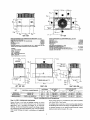
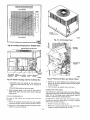
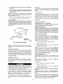
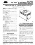
The 48JZ unit (See Fig, 1) is a fully self-contained,
combination
electric heat pump unit with gas-firod back-up heat designed for
outdoor installation (See Fig. 2 and 3 for unit dimensions). All unit
sizes have return and discharge openings for both horizontal and
MOUNT
DUCTS
downflow configurations,
and are factory shipped with all downflow duct openings covered. Units may he installed either on a
rooftop, a cement slab, or directly on the ground if local codes
permit (See Fig. 4 for roof curb dimensions).
Models with an N in the fifth position (available on single phase
only) of the model number are dedicated Low NOx units designed
for California installations.
NOTE:
lations.
These
Low NOx requirements
models
apply only to natural
meet the California
maximum
oxides
SEAL STRIp MUST BE IN
pLACE B_FORE pLACING
UNIT ON ROOF CURB
12k_3
gas instal-
PL_3E RIGGING STRAPS IN
BASEPAN SLOT (B_LC'_ RIGGING 1.1(_05)
BEFORE P,_*GIi*K3
C99015
of nitrogen
4 zl,h
I ommln,ore
(NOx) emissions requirements of 40 nanograms/jouIe or less as
shipped from the factory and must be installed in California Air
Quality Management Districts where a Low NOx rule exists.
UNIT
NOTE: In order for this unit to run as designed, you must install
with either Carrier's Thermidistat TM control or Dual fuel thermo-
024
030
332
346
151
157
22.0
22.0
558.5
558.5
14.50
15.30
368.3
388.6
stat. We recommend the Thermidlstat
speed blower motors.
036
343
402
156
182
22.0
23.0
558.5
584.2
15.30
16.3
388.6
414.0
431
526
195
239
21.5
23.5
546.1
596.9
16.3
16.3
414.0
414.3
RECEIVING
Step 1--CHECK
IDENTIFY
TM
control
MAXIMUM WEIGHT
A
B
UNIT 48JZ
if using variable
042
048
060
AND INSTALLATION
EQUIPMENT
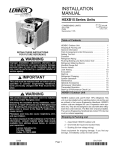
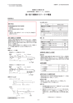
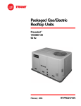
Fig. if--Suggested
UNIT
The unit model number and serial number are stamped on unit
identification
/ rating plate. Check this information
against shipping papers and job data.
Rigging
The unit may be installed either on a slab or placed directly on the
ground if local codes permit. Plane the unit on level ground
prepared with gravel for condensate discharge.
2
[)$_]
IZliI]
1583_
REAR VIEW
TOP VIEW
REQ'D CLEARANCES FOR OPERATION AND SERVICING. in. (mm)
REQ'D CLEARANCES TO COMBUSTIBLE
Evaporator coil access side ..................
Power entry side (except lot NEC requirements) .........
Unit top ..........................
S de opposite ducs .....................
Duct panel ........................
Top of unit .........................
Duct side of unit .......................
Side opposite ducts .....................
Bottom 0t unit .......................
Flue panel .........................
36 (914)
36 (914)
48 (1219
36 914
12 (304.8)"
*Minimum distances: If unit is placed less than 12 in. (304.8 ram) from wall
system, then the system pedormance may be compromised.
MATL. in. (mm)
14 (395.6)
2 (50.8)
14 (355.6)
0.50 (12.7)
36 (914.4)
NEC REQ*C CLEARANCES. in. (mrn)
Between units, power entry side ..............
Un t and ungrounded sudaces, power entry side .........
Unit and blOCkor conctele wails and other grounded
surfaces, contrel pox side .................
LEGEND
CG - Center of Gravity
CONC _ CondenSer
EVAP - Evaporator
NEG - National EleCtriCalCode
REQ'D - Required
Note: Dimensions are in in. (mrn)
42 1066.8)
35 {914
42 (1066.8)
A
• Z? ! DP
tl2.1
I_$_)
831.0
r_
721
LEFT SIDE ViEW
FRONTV_EW
RIGHT SIDE VIEWC99017
Ib
kg
X
Y
Z
208/230-1-60
310,0
141,0
35.02 (889,5)
22.0 (558.8)
14.5 (368.3)
16.0 (406.4)
48JZ030-040/060
208/230-1-60
324.0
147,0
37.02 (940,3)
22.0 (558,8)
15,3 (387.4)
17.6 (447,0)
48JZ836_060/090
208/230-1-60. 208/230-3-60
321,0
145,6
37.62 (940.3)
22.0 (558,8)
15.3 (387.4)
16,5 (419,1)
ELECTRICAL
48JZ024-040
CHARACTERISTICS
UNIT WEIGHT
CENTER OF GRAVITY
iN. (MM)
UNIT HEIGHT
IN. (MM)
"A"
UNIT
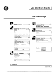
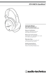
Fig. 2--48JZ024-036
Step 3--FIELD
FABRICATE
DUCTWORK
Secure all ducts to roof curb and building structure on vertical
discharge units. Do /lot connect ductwork to unit. For horizontal
applications,
unit is provided
with flanges on the horizontal
openings.
All ductwork
should be secured
to the flanges.
Insulate
and weatherproof
all external ductwork, joints, and roof openings
with counter flashing and mastic in accordance with applicable
codes.
Unit Dimensions
Ducts passing through an unconditioned
and covered with a vapor barrier.
space must be insulated
If a plenum return is used on a vertical
unit, the return should
ductod through the roof deck to comply
with applicable
A minimum
return-air
clearance
is not requin_d around
static shall not exceed -.25 in. wg.
ductwork.
be
fire codes.
Cabinet
HgHHHHmH
SU_pLf
oueT
Op[Mty_
loz._
I15_)
I
R[TURN
0U¢1
O_EliH5
i
I
(4 53)
+s 3
1_ 4+)
11]|]_
(l]|il
TOP VIEW
[l_.|3J
REARVIEW
REQUIREDCLEARANCETO COMBUSTIBLEMATL,
REQUIRED CLEARANCEFOR OPERATIONAND SERVICING
in. ram]
EV_.
CO,L
AOCSSS
mOB
..............................................................
36.00,
1914.0TOP OF UNIT ...................................................................................
POWER ENTRY SiDE ......................................................................
36.00 t91+.o! DUCT SIDE OF UNIT .........................................................................
SIDE OPPOSITE DUCTS ................................................................
(EXCEPT
POR
NEC
REOUmEMENTSl
OF UNIT .............................................................................
UNITTOP
.........................................................................................
36.00
[g14.0
$14.0
I BOTTOM
FLUE PANEL ....................................................................................
SIDEOPPOSITE
DUCTS ................................................................
36,00
DUCT PANEL ...................................................................................
in.
14.00
2.00
14.00
0.50
36.00
mm]
355.6]
50.6
355.6]
12.7
914.4
12+001304.81 "
NED, REQUIRED CLEARANCES.
"MINIMUM DISTANCES: IF UNIT IS PLACED LESS THAN 12.C0 [304,8] FROM
WALL SYSTEM, THEN SYSTEM PERFORMANCE MAYBE COMPROMISE+
MILLIMETERS [IN.]
B_TN EEN UNITS, POWER ENTRY SIDE .................................... 42.00 It 066.8
UNIT AND UNGROUNDED SURFACES, POWER ENTRY S DE ._36.00 9 4.0
UNIT AND BLOCK OR CONCRETE WALLS AND OTHER
GROUNDED SURFACES, POWER ENTRY SIDE ......................... 42.00 11066.8]
Z81
IOZO]
IIZ_.I
144.22J
LEFT SIDE VIEW
UNIT
FRONT VIEW
ELECTRICAL
CHARACTERISTICS
RIGHT SIDE VIEW
UNIT
UNIT WEIGHT
C99074
CENTER OF GRAVITY
IN. (MM)
HEIGHT
IN. (MM)
ib
kg
X
Y
Z
208/230-1-60, 208123C_3-60
380
172
40.98 (1040.9)
23.0 (584.2)
16,3 (412.8)
16.6 (421,6)
48JZ048-0901115/130
205/230-1-60, 208/230-3-60
409
186
40.98 (1040.9)
21,5 (946.1)
16.6 (422+1)
16.0 (457.2)
48JZ060-O95/115/130
205/230-1-60+ 205/230-3o60
504
229
42.96 (1091,1)
23.5 (596,9)
16.3 (412.8)
17.6 (447.0)
48JZ042-060/090
Fig.
Step 4--PROVIDE
3--48JZ042-060
CLEARANCES
The required minimum operating and service clearances are shown
in Fig. 2 and 3. Adequate combustion,
ventilation and outdoor coil
air must be provided in accordance
with section 5.3, Air for
Combustion and Ventilation, of the National Fuel Gas Code ANSI
(American
provisions
National
Standards
Institute) Z223.1 or applicable
of local building code. In Canada, follow sections 7.2,
Unit
Dimensions
7.3, or 7.4 or Can/CGA.
Installation
(Canadian
Codes or applicable
provisions
Gas Association)
of local building
B149
code.
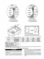
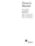
Roof Curb for Small
Roof Curb
Cabinet
for Larga
Cabinet
Note A: When unit mounting screw is used,
retainer bracket must also be used.
Note A: When unit mounting screw is used,
retainer bracket must alsO be used.
\
R/A
\/
/\
S/A
\
"'-"Gasket
around_
duct
Insulated
Gasket around
deck pan
outer edge \
\
C00076
UNIT SIZE
48JZ024-036
48JZ042-060
B
IN, (MM)
11(279)
A
IN. (MM)
ODS CATALOG NUMBER
CPRFCURB006A00
8 (203)
14 (356)
CPRFCURB007A00
CPRFCURB008A00
11(279)
163/16 (411)
8 (203)
14 (356)
CPRFCURBO09A00
163/16 (411)
C
IN, (MM)
D
IN, (MM)
16 1/2 (419)
16 1/2 (419)
28 3/4 (730)
28 3/4 (730)
17 3/8 (441)
40 1/4 (1022)
17 3/8 (441)
40 1/4 (1022)
NOTES:
1. Roof curb must be set up for unit beinlng
installed.
2, Seal strip must be applied, as require, to unit being installed,
3. Dimensions in ( ) are in millimeters.
4, Roof curb is made ol 16-gage steel,
5. Table lists only the dimensions, per part number, that have changed.
6. Attach ductwork to curb (flanges ol duct rest on curb).
7. Insulated panels: 1-in, thick fiberg{ass 1 Ib density.
8. Dimensions are in inCheS.
9. When unit mounting screw is used (see Note A), a retainer bracket must be used as well. This bracket must also be used when required by code for hurricane or
seismic conditions. This bracl_et is available through Micromed.
Fig.
--)
4---Roof
Curb
Dimensions
corner or under an overhead
under
Do not restrict outdoor
coil airflow. An air restriction
the outdoor-air inlet or the fan discharge
compressor life.
at either
can be detrimental
to
The outdoor tan pulls air through the outdoor coil and discharges
it through the top cover. Be sure that the fan discharge does not
recirculate to the outdoor coil. Do not locate the unit in either a
a partial
overhang
obstruction.
The minimum
(such as a normal
house
48-in. above the unit top. The maximum horizontal
partial overhang must not exceed 48-in.,
clearance
overhang)
extension
is
of a
Do not place the unit where water, ice. or snow from an overhang
or roof will damage or flood the unit. Do not install the unit on
carpeting, tile. or other combustible
materials. The unit may be
installed on wood flooring or on Class A. B. or C roof covering
materials.
1
2
H
Y
©
4
3
x
C00070
CORNER WEIGHTS (SMALL CABINET)
N
036
321
N
52
60.5
61.0
,¢t
88
49
121
57.3
95.0
108.2
57.8
99.5
102.7
024
_10
Comer Weight 1
Comer Weight 2
Corner Weight 3
Corner Weight 4
I
I
=o
1:=
o
CORNER WEIGHTS (LARGE CABINET)
Unit
042
048
030
,_P4
Unit
Totn) W_inht
380
409
5O4
Comer Weight 1
83
108
105
Comer Weight 2
Comer Weight 3
Comer Weight 4
52
115
130
48
125
128
76
130
193
,q
o
060
Total Weight
Fig. 5--48JZ Corner Weights
-..)
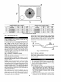
Step 5---RIG AND PLACE UNIT
Prime the trap with water. Connect
When installing the unit on a rooftop,
support the additional weight.
be sure the roof will
Use spreader bars or crate top when rigging the unit. The units
must be rigged for lifting (See Fig. 6). Refer to Table 1 for
operating weight. Use extreme caution to prevent damage when
of 3/4-in.
outlet end
drain tube
horizontal
a drain tube - using a minimum
PVC or 3/4-in. copper pipe (all field-supplled)
- at the
of the 2-in. trap. Do not undersize the tube. Pitch the
downward at a slope of at least l-in. for every 10 ft of
run. Be sure to check the drain tube for leaks.
1" (25mm) MIN.
moving the unit. Unit must remain in an upright position during all
rigging and moving operations.The
unit must be level for proper
condensate drainage; therefore, the ground-level
pad or accessory
2" (50mm) MIN.
roof curb must be level before setting the unit in place. When a
field-fabricated
support is used, be sure that the support is level
and properly supports the unit. Lifting point should be directly
over the center of gravity
Step 6---CONNECT
CONDENSATE
of condensate
fitting which exits through
2 and 3 for location).
Fig. 7--Condensate Trap
for the unit.
Step 7--INSTALL
DRAIN
NOTE: When installing condensate drain connection
comply with local codes and restrictions.
Model 4gJZ disposes
C99013
water
the compressor
be sure to
through
a 3/4 in. NPT
access
panel (See Fig.
FLUE HOOD
The flue hood assembly is shipped screwed to the coil panel in the
indoor blower compartment. Remove the service access panel to
locate the assembly.
Condensate water can be drained directly onto the roof in rooftop
installations (where permitted) or onto a gravel apron in groundlevel installations. Install a field-supplied condensate trap at end of
condensate connection to ensure proper drainage. Make sure that
the outlet of the trap is at least I in. lower than the drain condensate
connection to prevent the drain from overflowing
(See Fig. 7).
Prime the trap with water. When using a gravel apron, make sure
it slopes away from the unit.
If the installation
requires draining the condensate
water away
from the unit, install a 2-in. trap at the condensate connection to
ensure proper drainage (See Fig. 7). Make sure that the outlet of
the trap is at least 1 in. lower than the drain condensate connection,
This prevents
the drain from overt]owing.
Install the flue hood as follows:
1. This installation must conform with local building
with the National Fuel Gas Code (NFGC), ANSI
Canada, CAN/CGA B149.1, and B149.2) or NFPA
Fire Protection Association)
latest revision. Refer
cial and
applicable
local plumbing
local codes.
or
wastewater
codes
codes and
Z223.1 (in
(National
to Provinand
other
2. Remove flue hood from shipping location (inside the blower
compartment).
Place vent cap assembly over flue panel. Orient
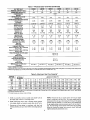
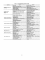
Table
UNIT SIZE 48JZ
NOMINAL CAPACITY (ton)
OPERATING WEIGHT (lb.)
COMPRESSORS
Quantity
REFRIGERANT (R-410A)
Quantity (Lb.)
REFRIGERANT METERING DEVICE
Orifice ID (In,)
AccuRater Piston
•
Orifice OD (in.)
OUTDOOR COIL
Rows...Flns/In.
Face Area (sq ft)
OUTDOOR FAN
Nominal Cfm
Dlameter (in.)
Motor HP (Rpm)
iNDOOR COIL
Rows..Fins/in.
Face Area (sq ft)
INDOOR BLOWER
(Standard PSC Motor)
Nominal Airflow (Cfm)
Size (in.)
Motor (HP)
FURNACE SECTION*
Burner Odfice No. (Qty...Ddll Size)
Natural Gas
Burner Orifice No. (Qty,..Ddfl Size)
Propane Gas
HIGH-PRESSURE SWITCH (psig)
Cut-out
Reset (Auto)
LOSS-OF-CHARGE /
LOW-PRESSURE SWITCH
(Liquid Line) (pslg)
Cut-out
Reset (auto)
RETURN-AIR FILTERS (tn.)t
Throwaway
BaSedon altitudeof 0 to 2000 ft.
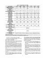
1--Physical
Data---Unit
48JZ
024040
2
030040
2-112
030060
2-1/2
036060
3
036090
3
042060
042090
3-1/2
3-1/2
310
324
324
321
Scrofl
1
321
380
380
7.0
8.9
8.9
9.3
9.3
9.5
9.5
0.061
0.061
0.061
0.067
0.067
0.073
0.073
0,032 (2)
0.040 (2)
0.040 (2)
0.040 (2)
o.o4o(2)
0.038 (2)
0.038 (2)
2...17
6.5
2...17
10.3
2...17
10.3
2..17
10.3
2...17
10.3
2...17
13.5
2...17
13.5
2350
22
1/8 (825)
2350
22
1/8 (825)
2300
22
1/8 (825)
2800
22
1/4 (1100)
28O0
22
1/4 (1100)
2500
22
1/6 (825)
2500
22
1/8 (1100)
3...15
3.7
3...15
3.7
3...15
3.7
4...15
3.7
4...15
3.7
3...15
4.7
3...15
4.7
800
10X10
1/4
1000
10X10
1/4
1000
10X10
114
1200
10X10
1/2
1200
10X10
1/2
1400
11X10
1/2
1400
11X10
1/2
2...44
2...50
2...44
2...50
2...36
2...46
2...38
2.-46
3...38
3..,46
2...38
2...46
3...38
3...46
610 +/- 15
420 +/- 25
20 +/- 5
45 +/- 10
20x20
i20.0xt
1 i20x24x1120x24xf
i20x24x1!
24x30xli
24x30xl
t Required filter sizes shown are based on the larger ot the ARI Air Conditioning and Refrigeration InstLtute)rated cooling aidlow or the heating aLdLowvelocity of 300
if/minute for high-capacity type. Air tLiterpressure drop tot non-standard filters must nol exceed 0.08 n, wg.
screw holes in vent cap with holes in the flue panel.
3. Secure fine hood to flue panel by insetting
a single screw on
the right side and the left side of the hood.
Step g--INSTALL
The
gas supply
the absence
GAS PIPING
pipe enters the unit through
When installing the gas supply line, observe local codes pertaining
to gas pipe installations. RetEr to the NFGC ANSI Z223.1 NFPA
54 latest edition (in Canada, CAN/CGA B 149.1, latest edition). In
pertinent
the access
hole
1.
provided. The gas connection to the unit is made to the l/2-in. FPT
gas inlet on the manual shutoff or gas valve.
Install a gas supply line that tans to the heating section. Refer to
Table 2 and the NFGC for gas pipe sizing. Do not use cast-iron
pipe. It is recommended that a black iron pipe is used. Check the
unit is operating. For propane applications, the gas pressure must
not be less than 7.0 in. wg or greater than 13 in. wg at the unit
connection.
An I/8-in. NPT plugged tapping, accessible for test gage connection. must be installed immediately
upstream of the gas supply
connection to the gas valve.
building
codes,
adhere
to the following
Avoid low spots in long runs of pipe. Grade all pipe 1/4 in. in
every 15 ft to prevent traps. Grade all horizontal
runs
downward to risers. Use risers to connect to heating section
and to meter.
2.
Protect all segments of piping system against physical and
thermal damage. Support all piping with appropriate straps,
hangers, etc. Use a minimum of one hanger every 6 ft. For
pipe sizes larger than I/2 in., follow recommendations
of
national codes.
3,
Apply joint compound (pipe dope) sparingly and only to male
threads of joint when making pipe connections. Use only pipe
dope that is resistant to action of liquefied petroleum gases as
specified by local and/or national codes. Never use Teflon
local utility for recommendations
concerning existing lines. Size
gas supply piping for 0.5 in. wg maximum pressure drop. Never
ltse pipe smaller than tile l/2-in. FPT gas inlet on the unit gas
valve.
For natural gas applications, the gas pressure at unit gas connection
must not be less than 4.0 in. wg or greater than 13 in. wg while the
of local
recommendations:
tape.
4. Install sediment
Fig. 8). This
condensate.
trap in riser leading
drip
leg
functions
to heating
as a trap
section. (S¢€
for
dirt
and
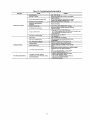
Table 1--Physical Data---Unit 48JZ (Continued)
UNIT SIZE 48JZ
NOMINAL CAPACITY (ton)
OPERATING WEIGHT (lb.)
COMPRESSORS
Quantity
REFRIGERANT (R-410A)
Quantity (lb.)
REFRIGERANT METERING DEVICE
Orifice ID (In.)
AccuRater
048090
4
048115
4
048130
4
060090
5
060115
5
060130
5
409
409
409
504
504
804
10.6
12.4
12.4
12.4
Scroll
1
Orifice OD (In.)
OUTDOOR COIL
Rows...Flns_l n.
Face Area (sq ft)
OUTDOOR FAN
Nominal Cfm
Diameter (in.)
Motor HP (Rpm)
INDOOR COIL
Rows...Flns/In.
Face Area (sq ft)
iNDOOR BLOWER
(Standard PSC Motor)
Nominal Airflow (Cfm)
Size (in.)
Motor (HP)
FURNACE SECTION"
Burner Orifice No. (Qty..Drill Size)
Natural Gas
Burner Orifice No. (Qty...Drgl Size)
Propane Gas
HIGH-PRESSURE SWITCH (psig)
Cut-out
Reset (Auto)
LOSS-OF-CHARGE /
LOW-PRESSURE SWITCH
(Uquld Line) (psig)
Cut-out
Reset (auto)
RETURN-AIR FILTERS (in.)1"
Throwaway
• Basedon altitudeof 0 to 2000 ft.
10.6
10.6
I
0.076
0.076
0.076
0.088
0.088
0.088
0.046 (2)
0.046 (2)
0.046 (2)
0.052 (2)
0.052 (2)
0.05_ (2)
2...17
13.5
2...17
13.5
2...17
13.5
2..17
15.4
2...17
15.4
2...17
15.4
3300
22
1/4 (1100)
3300
22
1/4 (1100)
3300
22
1/4 (1100)
3300
22
1/4 (1100)
3300
22
1/4 (1100)
3300
22
1/4 (1100)
4...15
4.7
4...15
4.7
4...15
4.7
4...15
5.7
4.,15
5.7
4._15
5.7
1600
11 X10
112
1600
11X10
112
t 600
11Xt0
1/2
t750
11X10
1.0
1750
11 X 10
1.0
1750
11 X 10
1.0
3...38
3...46
3...33
3...42
3...31
3...41
3...38
3...46
3...33
3...42
3..31
3...41
610 +/- 15
420 +/- 25
20+/- 5
45 +/" 10
24x30Xl
124x30x1
124x30x1
124x30xt
! 24x30x1
124x30xt
t Required filter sizes shown are based on the larger of the ARI (Air Conditioning and Refrigeration Institute) rated cooling aidlow or the heafing airflow velocity of 300
ft/minute for higfi-capacity type. Air filter pressure drop for non-staedard tilters must not exceed 0.08 in. wg.
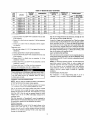
Table 2--Maximum
NOMINAL
IRON PIPE,
SIZE
0N.)
1/2
3/4
Gas Flow Capacity*
INTERNAL
DIAMETER
(IN.)
LENGTH OF PIPE, FTt
10
20
30
40
50
60
70
80
90
100
125
150
.622
175
120
97
82
73
66
61
57
53
50
44
40
1
.824
1.049
360
680
250
465
200
375
170
320
151
285
138
260
125
240
118
220
110
205
103
195
93
175
1 1/4
1 1/2
1.380
1.610
1400
2100
950
1460
770
1180
800
990
580
900
530
810
490
750
480
690
430
650
400
620
360
550
175
200
84
160
77
145
72
135
325
500
300
460
280
430
• Capacity of pipe in cu ft of gas per hr for gas pressure of 0.5 psig or less. Pressure drop of 0.5-in. wg (based on a 0.60 specific gravity gas). Refer to Table, National
Fire Protection Association NFPA 54.
_" This
length
includes
an ordinary
5. Install an accessible,
gas supply
external,
pipe within
6. Install ground-joint
unit manual shutoff
number
of fittings.
manual
6 ft of heating
main shutoff
valve in
section.
union close to heating section between
and external manual main shut-off valve.
7. Pressure-test all gas piping in accordance
with local and
national plumbing and gas codes before connecting piping to
unit.
NOTE: Pressure test the gas supply system after the gas supply
piping is connected to the gas valve. The supply piping must be
disconnected from the gas valve during the testing of the piping
systems when test pressure is in excess of 0.5 psig. Pressure test
the gas supply piping system at pressures equal to or less than 0.5
psig. The unit heating section must be isolated from the gas piping
system by closing the external main manual shutoff valve and
slightly opening the ground-joint union.
[N
3. Use a screwdriver and hammer to remove the panels in the
bottom of the unit base (See Fig. 9 & 10).
..=====,......"
.._
. CAP
C99020
Fig. 8--Sediment Trap
=---=
Unstable operation may occur when the gas valve and
manifold assembly are forced out of position while connecting improperly-routed
rigid gas piping to the gas valve. Use
a backup wrench on the square neck of the inlet side of the
gas valve when
i distortion
making
connection
of, the gas control
to avoid
,
SUPPLY
DUCT
OPENING
RETURN
DUCT
OPENING
C99011
Fig. 9_Supply and Return Duct Opening
strain on, or
piping.
Never use a match or other open flame when checking for gas
leaks. Never purge gas line into combustion chamber. Failure
to follow this warning could
serious injury or death.
result in an explosion
causing
8. Check for gas leaks at the field-installed and factory-installed
gas lines after all piping connections
have been completed.
Use soap-and-water
solution (or method specified by local
codes and/or
Step 9--INSTALL
regulations).
DUCT
ductwork
connects
to the roof
connections sizes and locations).
UNITS
curb
(See
FOR DOWNFLOW
Fig.
2 and
(VERTICAL)
3 for
DIS-
Before performing service or maintenance operations on the
system, turn off main power to unit and install lock-out tag.
Electrical
REMOVED
C99012
The unit has duct flanges on the supply- and return-air openings on
the side and bottom of the unit. For downshot applications,
the
CONFIGURING
CHARGE
COVERS
DUCT CONNECTIONS
shock could cause serious
1. Open all electrical
work.
disconnects
injury or death.
before
starting any service
2. Remove horizontal
duct coversto access bottom returnand
supply knockoutpanels.
Fig. 10--Vertical
Duct
Cover
Removed
4. If unit ductwork is to be attached to vertical
on the unit base (jackstand
time.
5. It is recommended
applications
that the base insulation
opening flanges
only),
do so at this
around the perim-
eter of the vertical return-air opening be secured to the base
with aluminum
tape. Applicable
local codes may require
aluminum tape to prevent exposed fiberglass.
6. Cover both horizontal duct openings with the provided
covers. Ensure opening is air- and watertight.
duct
7. After completing unit conversion,
and power up unit.
perform
all safety
checks
NOTEt The design and installation of the duct system must be in
accordance with the standards of the NFPA for installation of
the unit being installed:
I. Make all electrical connections in accordance with NEC
ANSI/NFPA
70 (latest edition) and local electrical codes
nonresidence-type air conditioning and ventilating systems, NFPA
90A or residence-type,
NFPA 90B; and/or local codes and
ordinances.
Adhere to the following
installing the duct system:
I. Units are shipped
duct covers).
criteria when
for horizontal
selecting,
duct installation
sizing,
governing
such wiring. In Canada, all electrical connections must be in accordance
with CSA standard C22.1
and
Canadian
(by removing
2. Select and size ductwork, supply-air registers, and return-air
grilles according to American Society of Heating, Refrigeration and Air Conditioning Engineers (ASHRAE) recommendations.
insulate
and weatherproof
all ductwork
systems.
Secure all ducts to building
located
HIGH-VOLTAGE
The field-supplied
a separate electrical service
disconnect
switch mounted
with a fieldat, or within
disconnect
switch box may be mounted on the
unit over the high-voltage
inlet hole when the standard power and
low-voltage entry points are used (See Fig. 2 and 3 for acceptable
location).
and airtight seal.
See unit wiring label and Fig. 11 for reference when making high
voltage connections.
Proceed as follows to complete the highvoltage connections to the unit.
7. Hash, weatherproof,
and vibration-isolate
all openings
in
building structure in accordance with local codes and good
building practices.
ELECTRICAL
local
sight from, the unit. Refer to the unit rating plate for maximum
fuse!circuit breaker size and minimum circuit amps (ampacity) for
wire sizing. (See Table 3 for electrical data.)
structure.
6. All units must have field-supplied
filters or accessory filter
rack installed in the return-air side of the unit. Recommended
sizes for filters are shown in Table 1.
Step 10--INSTALL
l and applicable
CONNECTIONS
The unit must have
supplied, waterproof,
5. Use flexible transition
between rigid ductwork and unit to
prevent transmission
of vibration.
The transition
may be
screwed or bolted to duct flanges. Use suitable gaskets to
ensure weathertight
Part
4. Do not damage internal components when drilling through
any panel to mount electrical hardware, conduit, etc. On
3-phase units, ensure phases are balanced within 2 percent.
Consult local power company for correction of improper
voltage and/or phase imbalance.
outdoors. Insulate ducts passing through unconditioned
space,
and use vapor barrier in accordance with latest issue of Sheet
Metal and Air Conditioning Contractors National Association
(SMACNA)
and Air Conditioning
Contractors
of America
(ACCA) minimum installation standards for heating and air
conditioning
Code
3. Be sure that high-voltage power to unit is within operating
voltage range indicated on unit rating plate.
3. Size all ductwork
for maximum
required
airflow (either
heating or cooling) for unit being installed. Avoid abrupt duct
size increases or decreases or performance
may be affected.
4. Adequately
Electrical
codes. Refer to unit wiring diagram.
2. Use only copper conductor
for connections
between
field-supplied
electrical disconnect
switch and unit. DO
NOT USE ALUMINUM
WIRE.
CONNECTIONS
(SEE UNIT WIRING
LABEL)
The unit cabinet must have an uninterrupted,
unbroken
electrical ground to minimize
the possibility
of personal
injury if an electrical fault should occur. This ground may
consist of an electrical wire connected to the unit ground lug
fi:i:
.
/_
•
I=m
GND
CONTROL
in the control compartment, or conduit approved for electrical
ground when installed in accordance
with NEC (National
Electrical Code) ANSI/NFPA
70 (latest edition) and local
electrical codes. In Canada, follow Canadian Electrical Code
FIELD-SUPPLIED
FUSED DISCONNECT
BOX
tOLOW-VOLTAGE
POWER LEADS"
(SEE UNIT
WIRING LABEL)
CSA (Canadian
Standards
Association)
C22.1 and local
electrical codes. Failure to adhere to this warning could result
in serious injury or death.
/
, O-
®
i O-
io.i
ioSPLICE
'-NL°LD-
BOX
FIELD CONTROL - VOLTAGE WIRING
FIELD HIGH - VOLTAGE WIRING
C01110
Fig. 11--High-
and Control-Voltage
Connections
Single phase units:
i. Run the high-voltage
control box.
2. Connect
l0
ground
(LI,
L2) and ground
lead to chassis ground
leads
connection.
into the
Table3---ElectrlcaIData_Unlt48JZ
UNIT
SIZE
48JZ
VOLTAGE
RANGE
V-PH-HZ
COMPRESSOR
INDOOR FAN
MOTOR
OUTDOORFAN
MOTOR
Min
Max
RLA
LRA
FLA
POWER SUPPLY
FLA
MCA
MAX FUSE
OR CKT BKR
2.0
2.1
19.8
22.9
30
35
4.1
4.1
4.1
26.8
21.0
33.0
40
30
50
24.3
32.3
24.1
35
50
35
024
208/230-1-60
187
253
13.5
61.0
0.9
030
208/230-1-60
187
263
15.9
73.0
0.9
208/230-1-60
187
253
16.9
83.0
1.6
208/230-.3--60
187
253
12.2
77.0
1.6
208/230-1-60
187
263
22.4
105.0
0.9
208/230-3-60
187
253
15.4
88.0
0.9
208/230-1-60
187
253
21.3
109.0
1.6
208/230-3-60
187
263
14.7
91.0
1.6
4.1
4.1
4.1
208/230--1-60
187
253
27.6
158.0
1.5
6.2
42.2
60
208/230-3-60
187
253
19.2
137.0
1.5
6.2
31.7
40
036
042
048
060
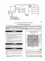
3. Locate the black and yellow wires connected
of the contactor.
4. Connect LI to black wire on connection
contactor.
Locate five 18-gage wires leaving control box, These low-voltage
connection leads can be identified by the colors red, green, yellow.
brown, and white (See Fig. 11). Ensure the leads are long enough
to be routed into the low-voltage splice box (located below right
side of control box). Stripped yellow wire is located in connection
box. Route leads through hole in bottom of control box and make
low-voltage connections (See Fig. 11). Secure all cut wires, so that
23 of the compres-
units:
1. Run the high-voltage
control box.
2. Connect
ground
(LI. L2, L3) and ground
4. Connect
field
compressor
LI
leads into the
they do not interfere
lead to chassis
ground connection.
3. Locate the black and yellow wires connected
of the contactor.
to black
HEAT
to the lines side
wire on connection
compressor
6. Connect
11 of the
required
13 of the
heat anticipator
must be properly
adjusted to
setting,
NOTE: For thermostat selection purposes, use 0.18 amp for the
approximate
required setting. Failure to make a proper heat
anticipator adjustment will result in improper operation, discomfort to the occupants
of the conditioned
space, and inefficient
energy utilization; however, the required setting may be changed
contactor.
FOR 208-V
of unit.
SETTING
ensure proper heating performance. Set the heat anticipator, using
an ammeter between the W and R terminals to determine the exact
field wire L3 to Blue wire from compressor.
PROCEDURES
with operation
ANTICIPATOR
The room thermostat
contactor.
5. Connect field wire L2 to yellow wire on connection
SPECIAL
Run the low-voltage leads from the thermostat, through the inlet
hole, and into unit low-voltage splice box.
11 of the compressor
5. Connect L2 to yellow wire on connection
sor contactor.
Three-phase
to the line side
OPERATION
slightly to provide
installation.
TRANSFORMER
a greater
degree
of comfort
for a particular
PROTECTION
The transformer
is of the energy-limiting
type. It is set
withstand a 30-see. overload or shorted secondary condition.
CONTROL
NOTE:
VOLTAGE
CONNECTIONS
This unit must be installed with either
or Dual fuel thermostat
Do not ttse any type of power-stealing
"C" comtectiott
at Slat).
a Thermidistat
TM
for proper system operation.
thermostat
Unit control problems
(no Common
may result.
Use no. 18 American Wire Gage (AWG) color-coded,
insulated
(35 C minimum) wires to make the control voltage connections
between the thermostat and the unit. If the thermostat is located
more than 100 ft from the unit (as measured along the control
voltage wires), use no. 16 AWG color-coded,
insulated (35 C
minimum) wires.
Dual fuel thermostat or Thermidistat '_t control is required for
proper operation of the dual fuel heat pump unit. Be sure to follow
the instructions supplied with the thermostat and control.
Standard
Connection
Remove knockout hole located in the flue panel adjacent to the
control access panel (See Fig. 2 and 3). Remove the rubber
grommet from the installer's packet (included with unit) and install
grommet in the knockout opening.
running wire through panel.
Provide
a ddp
loop befure
11
to
EXAMPLE: Supply voltage is 230-3-60.
A B C
AB=232V
FLA
LRA
MCA
CKT BKR
RLA
---
Full Load Amps
Locked Rotor Am s
Minimum Circuit Amps
Circuit Breaker
Rated Load Amps
LmENO
'PO
---
,, @
AC = 225 v
US
_lp
Average Voltage = 232 + 227 + 225
3
BG = 227 v
= 68._4
3
= 228
NOTES:
1. In compliance with NEC (National Electrical Code) requirements
for multimotor and combination load equipment (refer to NEC
Articles 430 and 440), the overcurrent protective device for the
unit shall be Power Supply fuse. Canadian units may be
fuse or circuit breaker.
2. Minimum wire size is based on 60 C copper wi_e. If other than
60 C wire is used, or if length exceeds wire length in table,
determine size from NEC.
3. Unbalanced 3-Phase Supply Voltage
Never operate a motor where a phase imbalance in supply voltage is greater than 2%. Use the following formula to determine
the percentage of voltage imbalance.
Determine maximum deviation from average vcttage.
(AB) 232- 228 = 4v
(BC) 228- 227= 1 v
(AC) 228 - 225 = 3 v
Maximum deviation is 4 v.
Determine percent of voltage imbalance.
% Voltage Imbalance = 100 x
4
228
= 1.75%
This amount of phase imbalance is satisfactory as it is below the
maximum allowable 2%.
% Voltage imbalance
= 100 x max voltage deviation from average voltage
average voltage
1
IMPORTANT: If the supply voltage phase imbalance is l
more than 2%, contact your local electric utility company
immediately.
I
(501106
Table 4--Legend
PRE-START-UP
b. Inspect for oil at all refrigerant tubing connections
and on
unit base. Detecting oil generally indicates a refrigerant
leak.
c. Leak test all refrigerant tubing connections using electronic
leak detector, halide torch, or liquid-soap solution.
If a
refrigerant leak is detected, see the Cheek for Refrigerant
Leaks section,
Failure to observe the following warnings could result in
serious injury or death:
1. Follow recognized safety practices and wear protective
goggles when checking or servicing refrigerant system.
d. inspect
2. Do not operate compressor or provide any electric power to
unit unless compressor
tecminal cover is in place and
secured.
3. Do not remove
compressor
terminal
carefully
goggles
and proceed
a. Shut off gas supply and then electrical
install lock-out tag.
to inspect
and prepare
as fol-
access
If the gas supply pipe was not purged before connecting
the unit, it will be full of air. It is recommended that the
ground joint union be loosened, and the supply line be
allowed to purge until the odor of gas is detected, Never
purge gas lines into a combustion chamber. Immediately
upon detection of gas odor, retighten the union. Allow 5
minutes
the unit for initial
panel.
3. Make the following
to elapse,
then light unit.
b. Make sure that outdoor fan blade is correctly positioned
fan orifice. Leading edge of outdoor fan blade should
I/2 in. maximum from fan orifice.
2. Read and follow instlxtctions
and INFORMATION
I
a. Make sure gas line is free of air. Before lighting the unit for
the first time, perform the following with the gas valve in
the "OFF" position:
power to unit and
startup:
I. Remove
fins with a fin comb.
Do not purge gas supply into the combustion chamber. Do not
use a match or other open flame to check fbr gas leaks.
Failure to follow this warning could result in an explosion
causing serious injury or death.
d. Carefully unsweat remaining tubing stubs when necessary. Oil can ignite when exposed to torch flame.
as follows
Be sure
conditions:
P'+__,._UJi[,]:
b. Relieve and recover all refrigerant from system using
both high- and low-pressure
ports.
c. Cut component connecting tubing with tubing cutter and
remove component from unit.
Proceed
straighten
Verify the following
refrigerant leak is suspected around compressor terminals.
5. Never attempt to repair brazed connection while refrigerant
system is under pressure.
6. Do not use torch to remove any component.
System
contains oil and refrigerant under pressure. To remove a
wear protective
connections.
e. Inspect coil fins. If damaged during shipping and handling,
cover until all electri-
cal sources are disconnected and tagged.
4. Relieve and recover all refrigerant from system before
touching
or disturbing
anything
inside terminal box if
component,
lows;
all field- and factory-wiring
that connections
are completed,
not rubbing against any
sharp sheet metal edges or refrigerant tubing and are tight.
on all WARNING,
CAUTION,
c. Ensure
labels attached to, or shipped with, unit.
from motor
housing
(See Fig. 12).
inspections:
a. Inspect for shipping and handling damages
lines, loose parts, disconnected wires, etc.
fan hub is 118 in. maximum
in
be
d. Make sure that air filter(s)
such as broken
e. Make sure that condensate
ensure proper drainage.
12
is in place.
drain trap is filled with water to
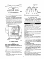
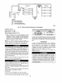
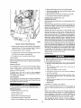
BURNER FLAME
• FAN GRILLE
1/8" (3•175mml MAX BETWEEN
MOTOR AND FAN HUB
MOTOR SHAFT
C99009
_/_ABURNIR
Fig. 12--Fan
f. Make sure that all tools and miscellaneous
been removed.
loose parts have
5. Compressors
are internally spring mounted.
remove compressor bold-down bolts.
Do not loosen or
C_2I
Fig. 14--Monoport
6. Each unit has 2 schrader-type
ports, one low-side located on
the suction line. and one high-side located on the compressor
discharge line. Be sure that caps on these ports are tight.
7. This unit has High Flow Valves located on the compressor
of a refrigerant
Burner
5. Charge unit with R-410A refrigerant,
using a volumetriccharging cylinder or accurate scale. Refer to unit rating plate
for required charge. Be sure to add extra refrigerant
to
hot
gas and suction tubes. Large black plastic caps with O-rings
distinguish these valves. These valves cannot be accessed for
service in the field. Ensure the plastic caps are in place and
tight or the possibility
NIFOLD
Blade Clearance
compensate
for internal volume of filter drier.
Step 2--START-UP
HEAT AND MAKE ADJUSTMENTS
leak could occur.
NOTE:
This unit is factory
Do not jumper
Make
sure that
equipped
any safety devices
burner
orifices
with natural gas orifices.
when operating
are properly
operation may occur when the burner orifices
misaligned.
the unit.
aligned.
Unstable
in the manifold
are
Follow the lighting instructions on the heating section operation
label (located inside the burner or blower access door) to start the
heating section.
NOTE:
Make sure that gas supply
gas piping has been checked
CHECK
HEATING
has been purged,
and that all
for leaks.
CONTROL
Start and check the unit for proper cooling control operation as
follows (see furnace lighting instructions located inside burner or
blower access panel):
/
MANIFOLD
1. Place room thermostat SYSTEM switch in the HEAT position
and the fan switch is placed in AUTO. position. Verify that the
PIPE PLUG
C99019
Fig. 13--Burner
outdoor
Assembly
air sensor setting
2. Set the heating
is above the outdoor
temperature
control
temperature.
of the thermostat
above
room temperature.
START-UP
Step 1--CHECK
Proceed as follows
charge the unit:
3. The induced-draft
FOR REFRIGERANT
to locate and repair a refrigerant
leak and to
reset the control,
ports.
2. Repair leak following
(R-410A)
Install a bi-fiow
whenever
Refrigerant
Service
filter drier suitable
3. Add a small charge of R-410A refrigerant
leak-test unit.
4. Recover refrigerant and evacuate
additional leaks are not found.
system
procedures.
thermostat has been satisfied•
for repair.
CHECK
GAS INPUT
Check gas input and manifold pressure after unit start-up (See
Table 5). If adjustment is required proceed as follows:
vapor to system and
to 500 Microns
break the 24-v power to W.
5. The indoor fan will turn on 45 sec. at_er the flame has been
established• The indoor fan will turn off 45 sec. after the
for use with Puron®
the system has been opened
the main burner should light within 5
sec. If the burners do not light, there is a 22-sec. delay before
another 5-sec. try. If the burners still do not light, this
sequence is repeated. If the burners do not light within 15
minutes from the initial call for heat, there is a lockout. To
1. Locate leak and make sure that refrigerant system pressure has
been relieved and reclaimed from both high- and low-pressure
NOTE:
motor will sta_.
4. After a call for heating,
LEAKS
if
•
13
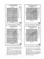
The rated gas inputs shown in Table 5 are for altitudes from sea
level to 2000 ft above sea level• These inputs are based on
SCHEMATIC 2081230-I-60
SUPPLY
P_[R
tomlclnm _
o
w
"--WSI
_
8L
LK
HP$
_3 9RII-
_,3o _ozl uN,It
-pNx
_[_Tn_
_a tC_n_
UNIT
COMPON[NT
O_lo00ltal
11¢I1_
ARRANGtMENT
[]
[_IP.
$[¢11_1
$[¢TI_ I
¢G_II_
601
L- 3r__1
....
DIP SWITCH SETTINGS
__I°
it_
,----,
....
---i
ekel n
nlglT($
i I[III
- - -_
_
_
j
||
IIINI,I|
Ill
_OIr
_Jll|
÷
C_
I l
i
LAIG[ ¢II_$$I$ L_&TI_I*
10 III11115
O
P[I
% i_1511[i LII_[5
I[IIII
IITIIIUll
II_III&T[
ILOI_I
I1€
_OIIPOII[NT$
pAIIII+
_[11_1
IILL
III_IUT|
III _
S[I_. IF OfT I_L
GOIO!
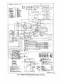
Fig.
15---208/230-1-60
Wiring
natural gas with a heating value of 1050 Btu/ft _ at 0.65 specific
gravity, or propane gas with a heating value of 2500 Btu/ft 3 at
1.5 specific gravity.
Diagram,
Unit 48JZ
For elevations above 2000 ft, reduce input 4 percent
1000 ft above sea level.
14
for each
EraOSl
8oa_o
R
(oe_
_
_
[-----_54
8L_)--W53
W5 _ 6LU
8RJ
BLK
Hp$
43 BRN--
3iZ)
UNIT
COHPON[NT
s[¢l_oN
°_TOOO_rAI
ARRANGE_EN!
[]
(o,u r _.,
GUD
DiP
iKr_ml_
SWITCH
SETTINGS
i_
w_t_s
....
--i
_ Iru I
m
c_
"-'a
_
mlts: I
_r _, w _
NI_II_
,1_1
r_lls_|
_
_K(o,
SCOIIII[_I
P[I I[¢
c I
I
--,-_,-,- ;-
_1@ ,(_
48JZ500002
1,.°
L4J
Fig. 16--208/230-3-60
Wiring
When the gas supply being used has a different heating value or
specific gravity, refer to national and local codes, or contact
your distributor to determine the required orifice size.
15
Diagram,
Units 48JZ
SCHEMATIC 2081230-I-60
II[LD
m
_PLt
I
_'OW(R
i
m
DiP
SWITCH SETTINGS
÷
[_,_
14eJ_500004
Fig. 17--208/230-1-60
ICM FlOP Wiring Diagram, Unit 48JZ
i6
l i 0
301101
Table 5--Heating
HEATING
INPUT
(BTUH)*
Inputs
GAS SUPPLY PRESSURE
(IN. WG)
Natural
Propanet
NUMBER
OF
ORIFICES
MANIFOLD
PRESSURE
(IN. WG)
Min
Max
Min
Max
Natural
Propane1*
40,000
2
4.0
13.0
4.0
13.0
3.5
3.5
60,000
2
4.0
13.0
4.0
13.0
3.5
3.5
90,000
3
4.0
13.0
4.0
13.0
3.5
3.4
115,000
3
4.0
13.0
4.0
13.0
3.5
• 3.7
130,000
3
4.0
13.0
4.0
13.0
3.5
3.5
f When a and is converted to propane, different size orifices must be used, See s_ _arate. natural-to-propane conversion kit instructions.
• Based on attitudes from sea level to 2000 ft above sea level, For altitudes above 2000 if. reduce input rating 4 percent tor each 1000/1 above sea level In Canada,
from 2000 ft above sea level to 4500 ft above sea level, de-rate the unit 10 percent.
I. Remove
valve.
These units are designed to consume the rated gas inputs
using the fixed orifices at specified manifold pressures as
shown in Table 5. DO NOT RE-DRILL
THE ORIFICES
UNDER
ADJUST
2. Turn regulator adjustment screw
input, or turn regulator adjustment
decrease input. Manifold pressure
3.6 in. wg. Unsafe operation of the
ANY CIRCUMSTANCES.
GAS
The gas input to the unit is determined by measuring the gas flow
at the meter or by measuring the manifold pressure. Measuring the
Measure
Gas Flow (Natural
must
4. Turn off gas supply to unit. Remove manometer
Measure Manifold Pressure (Propane Units)
The main burner orifices on a propane gas unit are sized for the
be
unit rated input when the manifold
level specified in Table 5.
Proceed
13) and connect
(number
5. Remove
valve.
of
6. Adjust
that the size of test dial is I cuft,
1. 32 sec. to complete
4. 112.5 x 1050=
manifold
one
value of the gas is 1050
CHECK
ft _ of gas flow/hr.
118,125 Btuh input.
and proceed
as follows
manometer
(See
adjustment
screw
screw on gas
to the correct
manifold
in Table 5. Turn adjusting
screw
manifold pressure, or turn adjusting
to decrease manifold pressure.
cover screw.
BURNER
FLAME
With burner access panel removed, observe the unit heating
operation. Watch the burner flames to see if they are light blue and
soil in appearance, and that the flames are approximately
the same
for each burner. Propane will have blue flame with yellow tips
(gee Fig. 14). Refer to the Maitltenance section for information on
burner removal,
one revohuion.
pressure
gas unit:
8. Turn off gas to unit. Remove manometer from pressure tap.
Replace pipe plug on gas valve, then turn on gas to unit. Check
for leaks.
If the desired gas input is 115,000 Btuh, only a minor change in the
manifold pressure is required.
Observe
input:
and connect
cover screw over regulator adjustment
regulator
7. Replace
2. 3600 + 32 = 112.5.
3. 112.5 x 1 =112.5
the
a call lbr Gas Heating.
pressure,
as specified
clockwise to increase
screw counterclockwise
7. Multiply result of Step 5 by Btu heating value of gas to obtain
total measured input in Btuh. Compare this value with heating
input shown in Table 5. (Consult the local gas supplier if the
heating value of gas is not known.)
Assume
matches
3. Turn on gas to unit.
4. Initiate
6. Multiply result of Step 4 by the number of cu ft shown for one
revolution of test dial to obtain cuft of gas flow per hour.
revolution takes 32 see., and the heating
Btu/ft -_.Proceed as follows:
reading
as follows to adjust gas input on a propane
2. Remove pipe plug on manifold
Fig. 13).
Record number of seconds for gas meter test dial to make one
revolution.
in Step 3 into 3600
pressure
1. Turn off gas to unit.
a call for Gas Heating.
5. Divide number of seconds
seconds in one hour).
from pressure
tap and replace pipe plug on gas valve. Turn on gas to unit and
check for leaks.
1. Turn off gas supply to unit.
EXAMPLE:
injury or unit damage
3. Replace cover screw cap on gas valve.
as follows:
2. Remove pipe plug on manifold (See Fig.
manometer. Turn on gas supply to unit.
4
clockwise to increase gas
screw counterclockwise
to
must be between 3.4 and
unit may result if manifold
Gas Units)
NOTE: All other appliances that use the same meter
turned off when gas flow is measured at the meter.
3. Initiate
screw on gas
for natural gas units. The
to determine the input of
Minor adjustment to the gas flow can be made by changing the
manitbld pressure. The manifold pressure must be maintained
between 3.4 and 3.6 in. wg. If larger adjustments
are required,
change main burner orifices following the recommendations
of
national and local codes.
Proceed
adjustment
pressure is outside this range. Personal
may result.
INPUT
gas flow at the meter is recommended
manifold pressure must be measured
propane gas units.
cover screw over regulator
to adjust gas
17
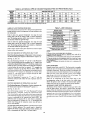
Table
6--Air
Delivery
(CFM) at Indicated
Temperature
Rise and Rated Heating
Input
HEATING
INPUT
(BTUH)
TEMPERATURE RiSE =F
20
25
30
35
40
45
50
56
60
65
70
40,000
1500
1200
1000
857
750
667
600
545
500
--
--
60,000
90,000
115_000
2250
---
1800
---
1500
2250
--
1286
1929
2464
1125
1668
2156
1000
1500
1917
900
1350
1725
818
1227
1568
750
1125
1438
692
1038
1327
-964
1232
130,000
--
--
--
2786
2438
2167
1950
1773
1625
1500
--
NOTE: Cashed areas do not fall within the approved temperature rise range of the unit.
AIRFLOW
AND TEMPERATURE
Table 7--LED Indications
RISE
The heating section for each size unit is designed and approved for
heating operation within the temperature-rise
range stamped on the
unit rating plate.
ERROR CODE
Table 6 shows the approved temperature
rise range for each
heating inpuL and the air delivery CFM at various temperature
rises. The heating operation airflow must produce a temperature
rise that falls within
Table
6 shows
the approved
the approved
Four Consecutive Limit Switch Faults
rise range
Ignition Lockout Fault
Induced-Draft Motor Fault
Rollout Switch Fault
for each
section
OF OPERATION-HEAT
Heat Pump Heating-Sequence
ture above
of Operation:
(option
l 1).
(See Fig. 15, 16 & 17)
On a call for heating, terminals "Y" and "G" of the Thermidistat TM or Dual Fuel thermostat are energized. The "Y" signal is sent
to the Defrost Board (DB) terminal "Y". The DB has a built in five
LIMIT SWITCHES
minute anti-short cycle timer which will not allow the compressor
to restart before the time delay has expired, "T2" energizes the
compressor
eontaetor via the High Pressure Switch (HPS) and
Normally
the Thermidista0
compressor contaetor
de-energized.
HEATING
M removes
and outdoor
SEQUENCE
Gas Heating--Sequence
low balance
point setpoint
the "Y"
motor
OF OPERATION-GAS
HEAT
of Operation:
temperature
Outdoor
of Thermidistuff
M (option
are
system cycles and the unit returns to normal
be-
AUXILIARY
11).
burners.
speed, the burner sequence
The
LIMIT
SWITCH
heating operation.
(ROLLOUT)
The function of the switch is to close the main gas valve in the
event of flame rollout. The switch is located above the main
On a call for heating, terminal "W" of the Thermidistat TM or Dual
Fuel thermostat is energized, starting the induced-draft
motor.
When the hall-eft_ct sensor on the induced-draft
motor senses that
the required
The limit switch is normally
When the air temperature
at the limit switch drops to the
low-temperature
setting of the limit switch, the switch closes
allows the ignition cycle to restart. The electric-spark ignition
(See Fig. 15, 16 & 17)
it has reached
limit switch (LS)-
opens the gas valve circuit and stops gas flow to the burners.
blower motor continues to run until LS resets.
and +'G" calls, the
fan and evaporator
closed
closed and opens on sensing excessive temperature
rise in the heat
exchanger compartment. Should the leaving-air temperature
rise
above the maximum allowable temperature, the limit switch opens.
When tile limit switch opens the IGC control circuit instantly
Low Pressure Switch (LPS). The compressor and outdoor fan start.
Thermidistat r_ "G" energizes the Integrated Gas Control (IGC)
tet_thnal '+G". Tile blower motor is energized through the "BM"
and "L2" terminals of the IGC.
When
8 Flashes
B. If more than one error code exists, all applicable
error COdeS will be
displayed in numerical sequence
C. This chart is on the wiring diagram located inside the burner access panel.
2.
A. This code indicates an internal processor fault that will reset itself in one
bOll=. Fault can be caused by stray RF signals in the structure or nearby. This
is a UL requirement.
B. Wrien W1 is energized
the burners will remain
on for a minimum
el 60
seconds+
Outdoor temperaTM
6 Flashes
7 Flashes
Internal Control Fault
PUMP
balance point setpeint of Thermidistat
4 Flashes
5 Flashes
Temporary one hour automatic
9 Flashes
reset fault (See note 2)
NOTES:
1.
A. There is a 3-sec.pause betweenerror codedisplays.
to adjust
airflow when required.
SEQUENCE
2 Flashes
3 Flashes
Flame Sense Fault
range.
temperature
Refer to htdoor Airflow attd Airflow Adjustments
HEATING
Off
1 Flash
Fan On/Off Delay Modified
Limit Switch Fault
heating input, and the air delivery CFM at various temperature
rises. The heating operation airflow must produce a temperature
rise that fails within the approved range.
heating
LED INDICATION
On
Normal Operation
Hardware Failure
When the temperature
at the auxiliary switch reaches
maximum allowable temperature
opening the gas wdve circuit and
The indoor fim motor (IFM) and
run until switch is reset. The IGC
7.
begins. This
t_nction is performed
by the integrated gas control (IGC). The
indoor-fan motor is energized 45 sec. after flame is established.
When the thermostat is satisfied and '+W" is de-energized,
the
burners stop firing and the indoor-fan motor shuts off after a
45-see. time-off delay.
An LED (light-emitting
diode) indicator is provided on the control
board to monitor operation.
The control board is located by
removing the burner access panel. During normal operation, the
LED is continuously on. (See Table 7 for error codes.)
18
the
and opens, the IGC circuit opens,
stopping gas flow to the burners.
induced drafi motor continue to
LED will display FAULT CODE
Step 3_START-UP
MENTS
COOLING
COMPRESSOR
AND MAKE ADJUST-
On 3-phase
ROTATION
units with scroll compressors,
it is important
to be
certain compressor is rotation in the proper direction, To determine
whether or not compressor is rotating in the proper direction:
1. Connect
fittings.
Complete the required procedures given in the Pre-Sturt-Up
section before starting the unit.
Do not jumper any safety devices when operating the unit.
Do not operate the compressor
in cooling mode when the
outdoor
ambient
temperature is below
kit is installed).
40°F
(unless
accessory
SEQUENCE
low-
pressure
pressure
If the suction pressure does not drop and the discharge
does not rise to normal levels:
pressure
The suction
their normal
NOTE:
is as follows:
any two of the unit power
These
completed
leads.
CHECKING
an elevated
is rotating
in the wrong direction,
level of noise
AND ADJUSTING
now move to
and does not provide
REFRIGERANT
CHARGE
with R_IOA
refrigerant,
NOTE: Adjustment
of the refrigerant
charge is not required
unless the unit is suspected of not having the proper R-410A
charge, The charging label and the tables shown refer to system
2. "O" terminal energizes Reversing Valve (RV) through Defrost
Board (DB),Note:
The RV remains energized
while the
Thermidistat J_'E
cooling mode is selected.
3. "Y" terminal energizes DB "Y". At_er 5 minute time delay of
DB terminals "TI" & "T2" has expired, ifLPS and HPS safety
temperatures
and pressures
An accurate
superheat,
in cooling
mode only.
thermocouple-
or thermistor-type
ther-
mometer, a sling psychrometer,
and a gauge manifold arc required
when using the superheat charging method for evaluating the unit
charge. Do not use mercury or small dial-type thermometers
because they are not adequate for this type of measurement,
start-
4. "G" terminal energizes
"BM" terminal of Integrated
Control (IGC) and the indoor motor starts.
When the compressor
levels should
The refrigerant system is fully charged
tested, and factory-sealed.
circuits
contactor is energized
tan motor,
and discharge pressure
start-up levels.
the unit makes
cooling.
1. When the room temperature
rises to a point that is slightly
above the cooling control setting of the thermostat,
the
thermostat completes circuit between thermostat terminal "R"
switches are closed. Compressor
ing the compressor and outdoor
and discharge
2. Reapply power to the compressor.
OF OPERATION
to terminals "Y", "G" and "O".
through the thermostat:
to suction
3. The suction pressure should drop and the discharge
should rise, as is normal on any start-up.
1. Reverse
With the room thermostat SYSTEM switch in the COOL position
and the FAN switch in the AUTO. position, the cooling sequence
of operation
gages
2. Energize the compressor.
Do not rapid-cycle the compressor. Allow 5 minutes between
"on" cycles to prevent compressor damage.
COOLING
service
Gas
NOTE:
Once the compressor
has started and then stopped, it
should not be started again until 5 minutes have elapsed. The
cooling cycle remains "on" until the room temperature drops to a
point that is slightly below the cooling control setting. The
thermostat opens tbe circuit between thermostat terminal R to
terminals Y, O and G. Tbese open circuits de-energize contactor
coil C and BM of the IGC. Tbe outdoor and compressor motors
stop. After a 30-see. delay, the blower motor stops. The unit is in
a "standby" condition,
the room thermostat.
CHECKING
UNITS)
waiting for the next "call for cooling"
COOLING
CONTROL
Start and check the unit for proper
follows:
1. Place
room
thermostat
OPERATION
cooling
SYSTEM
control
switch
Refrigerant
Charge-- Amount of refrigerant charge is listed on
unit nameplate (also refer to Table 1). Refer to Corporate GTAC
2-5 Charging, Recovery, Recycling,
and Reclamation
training
manual and the following procedures.
from
(NON-ICM
operation
in OFF
NOTE: Unit panels must
during charging procedure.
as
be in place
when
unit is operating
1. No Charge- Use standard evacuating techniques. After evacuating system, weigh in the specified amount of refrigerant
(Refer to Table 1),
position.
Observe that blower motor starts when FAN switch is placed
in ON position and shuts down when FAN switch is placed in
AUTO. position.
2. Place SYSTEM switch in COOL position and FAN switch in
AUTO. position. Set cooling control below room temperature.
2. Low-Charge
Cooling- Using Cooling Charging Charts (Fig
20-25), vary refrigerant until the conditions of the appropriate
chart are met. Tbese charging cbarts are different from type
normally used. Charts are based on charging the units to the
correct superheat for various operating conditions. Accurate
Observe that compressor,
outdoor tan, and indoor blower
motors start. Observe that cooling cycle shuts down when
control setting is satisfied. The indoor fan will continue to ran
for 30 sec.
pressure gauge and temperature sensing device are required.
Connect the pressure gauge to the service port on the suction
line. Mount the temperature sensing device on the suction line
and insulate it so that outdoor ambient temperature does not
affect the reading. Indoor air (CFM)
normal operating range of the unit.
3. When using an auto-changeover
room thermostat, place both
SYSTEM and FAN switches in AUTO. positions. Observe
3. Using Cooling
that unit operates in Heating mode when temperature control
is set to "call for heating"
(above morn temperature) and
operates in Cooling mode when temperature control is set to
"call for cooling"
(below room temperature).
Charging
Charts-
must
Compare
be within
outdoor-air
the
tem-
perature (*F db) and the suction line pressure (psig) and
temperature with corresponding
charging
chart (See Fig.
20-25).
19
OUTDOOR CC4L
INDOOR COIL
LCS
Meledng
Posilton
LEGEND
HPS - High Pressure Switch
LCS - Loss of Charge Switch
z_:
AccurateP Metering Device
]
Arrow indicates direction of flow
C_
Fig. 18--Typical
EXAMPLE: IFig. 20)
Outdoor Temperature.....85
Heat Pump Operation,
Table
F
Suction Pressure......145
psig
Suction Temperature
should be...70 F
(Suction Temperature
may vary +/- 3°1::)
4. Using a tolerance
of +/- 3°F, add refrigerant
if actual
temperature is more than 3*F higher than proper suction-tube
If the problem
refrigerant
INDOOR
causing
the
inaccurate
leak, refer to the Check for Refrigerant
AIRFLOW
AND AIRFLOW
readings
8-Color
Mode
Coding
for 208/230-V
Motor
Leads
3-SPEED
2-SPEED
black = high speed
blue = medium speed
black = high speed
red = low speed
red = low speed
is attached to terminal BM for single- and 3-phase units. To change
the speed, remove and replace with lead for desired blower motor
speed. Insulate the removed lead to avoid contact with chassis
temperature,
or remove refrigerant if act-aM temperature
is
more than 3°F lower than required suction-tube temperature.
Recheck the readings as charge is adjusted.
NOTE:
Heating
parts.
is a
MAINTENANCE
Leaks section.
To ensure continuing
high performance
and to minimize the
possibility of premature equipment failure, periodic maintenance
must be performed
on this equipment.
This combination
ADJUSTMENTS
Vml[,-Z_rI_0TSI
For cooling operation, the recommended
airflow is 350 to 450
cfm for each 12,000 Btuh of rated cooling capacity. For
heating/cooling unit should be inspected at least once each year by
a qualified service person. To troubleshoot
cooling or heating
components of units, ret_r to Tables 1 I, 12 and 13.
heating operation, the airflow must produce a temperature rise
that fails within the range stamped on the unit rating plate.
NOTE: Consult your
maintenance contract.
Table 6 shows the temperature rise at various airflow rates. Table
10 shows both heating and cooling airflows at various external
static pressures. Refer to these tables to determine the airflow for
the system being installed.
NOTE: Be sure that all supply- and return-air grilles
free from obstructions, and adjusted properly.
can cause serious
Airflow can be changed
blower motor.
injury
are open,
THIS EQUIPMENT.
of the
All 48JZ units are factory wired for low speed and may need to be
wired for medium or high speed in the field.
For 208/230V
For color coding on the 208/230V
motor leads, see Table
about
the availability
of a
perform any maintenance on this equipment other than those
procedures recommended
in the User's Manual. FAILURE
TO HEED THIS WARNING COULD RESULT IN SERIOUS INJURY OR DEATH AND POSSIBLE DAMAGE TO
or death.
by changing the lead connections
dealer
The ability to properly perform maintenance
on this equipment requires certain expertise, mechanical skills, tools, and
equipment, If you do not possess these, do not attempt to
Before changing blower speed, shut off gas supply. Then
disconnect electrical power to the unit . Electrical shock or
explosion
local
8.
To change the speed of the blower motor, remove the fan motor
speed leg lead t?om the blower relay (BM on the 1GC). This wire
20
INDOOR COIL
C:3
LCS
OLff!).OOR
Ci
BypaSs
Position
LEGEND
HPS - High Pressure Switch
LCS - LOSSof Charge Switch
_;
Accurate(" Metering Device
]
Arrow indicates direction of flow
C00096
Fig. 19---Typical Heat Pump Operation, Cooling Mode
Table 9---Filter Pressure Drop (In. wg)
FILTERSIZE
500
600
700
800
900
1000
1100
1200
1300
20X20X1
20 X 24 X 1
OmO50.07
....
0.08
0.10
0.12 0.13
O.O9 0.10
0.14
0.11
0.15
0.13
...........
0114 0115
0c9M0,10
0.16
24X30Xl
.......
0107
0.08
1400
1500
cF
¥!!|','l._l
_l(I)2b'l
Failure to tollow these warnings
or death:
1600
Oil
1700
........
1
0m_2
1800
1900
0"13
0'14
(Ct24) 60 Hz COOLING
2000
0615
CHARGING
2100
0mRS
2200
2300
0117
0
"18
CHART
FO="use with units using R4t 0a Refrigerant
could result in serious injury
1. First, turn off gas supply to the unit. Then turn off electrical
power and
maintenance
install lock-out tag before
or service on the unit.
2. Use extreme caution
with any mechanical
any
F
when removing panels and parts. As
equipment, personal injury can result
from sharp edges, etc.
3. Never place anything combustible
with. the unit.
4. Should overheating
performing
C
ITS
t_
either on. or in contact
¢t
Is
71
21
4s
1
occur or the gas supply fail to shut off,
turn off external main manual gas valve to the unit. Then
shut off electrical supply.
tion when servicing.
L, UUU_
Fig.
20mCOoIIng
Charging
Chart,
48JZ024
Units
death.
The minimum
follows:
1. Inspect
maintenance
requirements
for this equipment
are as
Clean
when
2. Inspect indoor coil. outdoor coil drain pan, and condensate
drain each cooling season tbr cleanliness.
Clean when necessary.
air
tilter(s)
each
month.
necessary. Certain geographical
frequent inspections.
locations
or
replace
may require
3. Inspect blower motor and wheel for cleanliness at the beginning of each heating and cooling season. Clean when necessary. For first heating and cooling season, inspect blower
more
21
Table 10---Wet Coil Air Delivery* - Horizontal and Downflow Discharge Unit 48JZ024-060 (Deduct 10 percent for 208 Volts)
230 VOLT
Unit
0.0
0.1
0.2
0.3
External
0,4
Wa_s
279
282
280
277
276
Motor Speed
Low
024
Med
High
Low
030
Med
High
Low
036
Med
High
Low
042
Med
Low
046
Med
High
Low
060
Med
High
(in. wg)
0.6
0.7
0.8
0.9
1,0
......
Cfm
582
801
738
674
604
Wa_s
--
--
--
373
367
361
356
351
--
--
--
Cfm
--
--
--
936
868
797
719
626
--
--
......
--
Wa_s
.....
463
452
439
428
--
--
Cfm
.....
956
878
794
702
--
--
WaRs
243
244
242
.....
........
Cfm
885
842
786
WaRs
353
339
333
330
326
320
Cfm
1195
1134
1070
997
911
818
.....
Watts
Cfm
---
---
---
443
1230
436
1145
426
1061
416
977
406
888
397
786
---
---
........
Watts
490
463
446
432
418
403
389
378
--
--
--
Cfm
1431
1398
1347
1281
1205
1118
1024
921
--
--
--
WaRs
--
513
501
488
474
459
443
428
--
--
--
Cfm
--
1491
1426
1351
1267
1175
1077
976
--
--
--
WaRs
Cfm
---
---
645
1484
636
1410
627
1330
616
1243
605
1147
593
1044
583
936
---
---
WaRs
634
618
608
598
583
562
534
502
473
454
457
Clm
1669
1599
1545
1498
1448
1391
1326
1257
1189
1132
1101
WaRs
--
--
--
733
704
672
638
004
574
660
536
Cfm
--
--
--
1746
1688
1630
1566
1492
1399
1279
1120
797
1727
773
1632
751
1537
727
1423
690
1308
--
Watts
Cfm
High
StOic Pressure
0.5
......
......
Watts
591
578
573
568
559
544
524
500
--
--
Cfm
1554
1523
1496
1467
1432
1387
1332
1269
--
--
--
WaRs
755
737
719
699
678
653
627
602
579
562
556
Cfm
1834
1802
1758
1706
1648
1585
1520
1455
1392
1332
1276
WaRs
Cfm
---
---
---
890
1943
858
1870
828
1793
801
1711
777
1624
756
1531
734
1433
709
1329
....
WaRs
589
576
569
566
559
541
499
Cfm
1946
1891
1836
1779
1718
1651
1577
....
WaRs
750
733
715
695
673
648
623
593
577
--
--
Cfm
2189
2097
2021
1952
1883
1809
1727
1635
1530
--
--
Wa_s
Cfm
---
879
2337
850
2159
821
2050
795
1974
772
1905
750
1824
728
1722
701
1597
---
---
• Air delivery values are without air tiller.
NOTE: Deduct field-supplied air tilter pressure drop to obtain external static pressure available for ducUng.
wheel bi-monthly
4. Check electrical
proper operation
when necessary.
to determine
proper cleaning
INDOOR
frequency.
connections
for tightness and controls for
each heating and cooling season. Service
5. Check and inspect heating section before each heating
Clean and adjust when necessary.
6. Check flue hood and remove
any obstructions,
BLOWER
AND MOTOR
NOTE: All motors are prelubricated.
these motors.
Do not attempt to lubricate
For longer life, operating economy,
and continuing
clean accumulated
dirt and grease from the blower
motor annually.
season.
efficiency,
wheel and
if necessary.
AIR FILTER
Never
operate
the unit without
a suitable
air filter
Before cleaning the blower motor and wheel, turn off gas
supply. T/ten turn off and tag electrical power to the unit.
Failure to adhere to this warning could cause serious injury or
death.
in
return-air duct system Always replace the filter with the same
dimensional size and type as originally installed. (See Table
1 tot recommended
filter sizes.)
Cleaning
the Blower Motor and Wheel
1. Remove and disassemble
Inspect air filter(s)
at least once each month and replace
(throwaway-type)
or clean (cleanable-type)
at least twice during
each heating and cooling season or whenever the filter(s) becomes
clogged with dust and/or lint.
a. Remove
unit access
blower assembly
and internal blower
as follows:
panels.
b. Disconnect motor lead from blower relay (BR). Disconnect
yellow lead from terminal L2 of the contactor.
22
(030) 60 Hz CCOUNG CHARGING CHART
For Use with Units Using R410a Rel;lger_nt
(042) 60 Hz COOLING
CHARGING
CHART
For use with units using R41 Ca Refrigerant
I
_LlttF4_Q
otno0_
i
F
t25
C
52
it5
106
46
41
35
35
35
I
F
C
115
46
K
15
24
¢5
R
zl
K
58
7
gJGrcwU_ rBe_t
_
_
C00083
Fig. 21--Cooling
Charging
Chart,
48JZ030
C00085
Units
Fig. 23--Cooling
(036) 60 HZ COOLING
CHARGING
CHART
For USII with ur,=t$ USing R4 1 0*3 RI_ frig er _tl_t
Charging Chart, 48JZ042 Units
(048) 60Hz COOLING
CHARGING
For use with units using R410a
CHART
Refrigerant
F
CU10OOA
115
C
$2
t_
C
105
41
95
115
46
10S
4t
R
21
45
?
35
85
75
N
45
7
I
e
_=
w
I
GO001
Fig. 22--Cooling
Charging
Chart,
48JZ036
C00086
Units
Fig. 24--Cooling
c. On all units, remove blower assembly from unit. Remove
screws securing blower
to blower partition and slide
assembly out. Be careful not to tear insulation in blower
compartment.
a.
C.
e. Loosen setscrew(s)
that secures wheel to motor shaft.
Remove
screws that secure motor mount brackets
to
2. Remove
and slide motor and motor mount
Ensure proper reassembly
Chart,
48JZ048
Units
by marking wheel orientation.
b. LiR wheel from housing. When handling and/or cleaning
blower wheel, be sure not to disturb balance weights (clips)
on blower wheel vanes.
d. Ensure proper reassembly
by marking blower wheel and
motor in relation to blower housing before disassembly.
housing,
Charging
Remove caked-on dirt from wheel and housing with a
brush. Remove lint and/or dirt accumulations from wheel
and housing with vacuum cleaner, using soft brash attachmeat, Remove grease and oil with mild solvent.
out of housing.
and clean blower wheel as follows:
d. Reassemble
23
wheel into housing.
F
C
12S Q I
IS
II
IS
7
FRONT
ACCESS
PANEL
C99091
Fig. 27--Unit Access Panel
G_7
Fig. 25---Cooling Charging Chart, 48JZ060 Units
BLOWER
HOUSING
INDUCED DRAFT MOTOR MOUNT
2 SETSCREWS
(HIDDEN)
LLOUT
VENT HOOD
IN SHIPPING
LOCATION
FLUE /'
COLLECTOR
BOX
SWITCH
BLOWER
HOUSING
BURNER
RACK
MOUNTING
SCREW
C99085
C99022
Fig. 26---Blower
Housing
and Flue Collector
Fig. 28---Removal
Box
3. Remove
e. Reassemble
motor into housing. Be sure setscrews are
tightened on motor shaft flats and not on round part of
shaft,
of Motor and Blower
the 12 screws holding
the flue collector
(See Fig. 26. 28 & 29) to the heat exchanger
the heat exchangers.
4. Clean all surfaces,
as required,
Wheel
box cover
assembly,
Inspect
using a wire brush.
f. Reinstall blower panel _nd unit access panel.
3. Restore
electrical
power
proper blower rotation
cooling cycles.
to unit.
and motor
Start
unit
COMBUSTION-AIR
and check for
speeds during
beating
Clean periodically to assure proper airflow and heating efficiency.
Inspect blower wheel every fall and periodically during the heating
and
season. For the First heating season, inspect blower
monthly to determine proper cleaning frequency.
FLUE GAS PASSAGEWAYS
To inspect
exchanger:
the flue collector
BLOWER
box and upper
areas of the heat
bi-
To inspect blower wheel, remove draft hood assembly. Shine a
flashlight into opening to inspect wheel, if cleaning is required.
remove motor and wbeel as follows:
1. Remove the combustion
blower wheel and motor assembly
according to directions in the Combustion-Air
Blower section.
2. Remove the 3 screws holding the blower housing
collector box cover (See Fig. 28).
wheel
to the flue
I. Remove
unit access
2. Remove
the 7 screws that attach induced-draft
lag plate to blower
24
panel (See Fig. 27).
motor mount-
housing (gee Fig. 26 & 28).
6. Remove
ignitor and sensor wires at the ignitor module.
7. Remove
the mounting
screw that attaches
the burner
rack to
the unit base (See Fig. 28).
8. Slide the burner rack out of the unit (See Fig. 26 and 29).
9. To reinstall,
reverse the procedure
OUTDOOR COIL, INDOOR
CONDENSATE DRAIN
outlined above.
COIL, AND
Inspect the Outdoor coil. Indoor coil. and condensat_
once each year,
drain at least
The coils are easily cleaned when dry; therefore, inspect and clean
the coils either before or after each cooling season. Remove all
obstructions,
including weeds and shrubs, that interfere with the
airflow through the outdoor coil.
Straighten
bent fins with a fin comb.
If coated
with dirt or lint,
clean the coils with a vacuum cleaner, using the soft brash
attachment.
Be caret_l not to bend the fins. If coated with oil or
grease, clean the coils with a mild detergem-aod-water
solution.
Rinse coils with clear water, using a garden hose. Be careful not to
splash water on motors, insulation, wiring, or air filter(s). For best
results, spray outdoor coil fins from inside to outside the unit. On
units with an outer and inner outdoor coil, be sure to clean between
the coils. Be sure to flush all dirt and debris from the unit base.
C99086
Fig.
29---Burner
Rack
Inspect the drain and condensate drain line when inspecting the
coils. Clean the drain and condensate drain line by removing all
foreign matter from the drain. Flush the drain and drain tube with
clear water. Do not splash water on the insulation, motor, wiring,
or air filter(s). If the drain tube is restricted, clear it with a
Removed
3. Slide the motor and blower wheel assembly out of the blower
housing (See Fig. 28). Clean the blower wheel, If additional
cleaning is required, continue with Steps 4 and 5.
4. To remove
blower, remove
"plumbers snake" or similar probe device. Ensure that the auxiliary
drain port above the drain tube is also clear
2 setscrews.
5. To remove motor and cooling fan assembly, remove
that hold blower housing to mounting plate.
6. To reinstall,
reverse the procedure
outlined
4 screws
OUTDOOR
FAN
above.
LIMIT SWITCH
Remove unit access panel, then the blower door to gain access to
the limit switch. The limit switch is located above the indoor
unit. Damage
to unit may result.
blower housing.
BURNER
1. Remove
IGNITION
Unit is equipped with a direct spark ignition 100 percent lockout
system. Ignition module is located in tbe control box. Module
contains a self-diagnostic
LED. During servicing, ret_r to label
diagram
occurs,
unit
may
be
reset
by
either
3. Inspect the fan blades
switch to
At the beginning of each heating season, inspect for deterioration
or blockage due to corrosion or other causes. Observe the main
and adjust,
6, Ensure that setscrew
when tightening,
if necessary.
7. Replace
Remowd
the gas train tbr servicing:
Remove
2. Shut off power to unit.
unit access
4. Disconnect
5. Remove
gas piping
engages
the flat area on the motor shaft
CONTROLS
AND WIRING
access
panel
to locate
all the electrical
controls
and
noticed, disassemble the connection, clean all the parts, re-strip the
wire end and reassemble the connection properly and securely.
panel (See Fig. 26).
at unit gas valve.
wires connected
and slide the
wiring. Check all electrical connections
for tightness, Tighten all
screw connections,
If any smoky or burned connections
are
1. Shut off main gas valve.
3. Remove
or bends.
loosen the setscrew
Inspect and check the electrical controls and wiring annually. Be
sure to turn off the gas supply, and thetl the electrical power to the
unit.
gas train, do not hit or plug orifice spuds.
of Gas Train
To remove
on top cover to
grille.
ELECTRICAL
When servicing
grille and motor to
5, When replacing fan blade, position blade so the hub is i/8 in.
away from the motor end, (I/g in. of motor shaft will be
visible. See Fig. 12).
BURNERS
burner flames
for cracks
4. If fan needs to be removed,
fan off the motor shaft.
momentarily
interrupting power supply to unit or by turning selector
OFF position at the thermostat.
MAIN
outdoor motor
2. Turn motor/grille assembly upside down
expose the fan blade.
for LED interpretation.
If lockout
6 screws holding
top cover.
to gas valve.
After inspecting the electrical controls and wiring, replace the
access panel. Start the unit, and observe at least one complete
Mark each wire.
25
7,
m
"11
.-I
O
i o
Speedup
Pins
Fig. 30--Defrost Control Board
heating
cycle and one complete
operation. If discrepancies
cycles, or if a suspected
cooling
cycle
to ensure
proper
field-selectable
time period (DIP switch 1 and 2 on the board)
between defrost cycles of 30, 60, 90, or 120 minutes (factory set at
30 minutes).
are observed in either or both operating
malfunction
has occurred, check each
electrical component
with the proper electrical instrumentation.
Refer to tile unit wiring label when making these checkouts.
NOTE:
Refer to the heating and/or cooling
in this publication
operation
HEAT
as
PUMP SYSTEM
Defrost
Control
QUIET
SHIFT
an
sequence
aid in determining
To initiate a forced defrost, two options are available
the status of the defrost thermostat.
of operation
proper
If defrost thermostat is closed, speedup pins (J 1) must
by placing a flat head screw driver in between for
releasing,
to observe a complete defrost cycle. When
Shift switch is selected, compressor will be turned off
control
ITEMS
Quiet Shift is a field-selectable
defrost mode, which will eliminate
40 sec, before starting
short defrost cycle will be observed (actual length is dependent
upon the selected Quiet Shift position). When Quiet Shift switch is
in ON position, the length of defrost is I minute (30 see
compressor off period followed by 30 sec of defrost with compressor operation). On return to heating operation, compressor will
again turn off for an additional 30 see and the outdoor fan for 40
see. When the Quiet Shift is in OFF position,
cycle will be observed.
in the Heating
only a brief 30 sec
If it is desirable to observe a complete defrost in warmer
the defrost thermostat must be closed as lbllows.
Defrost
The defrost control
be shorted
5 see and
the Quiet
for two 30
If defrost thermostat is in open position, and speedup pins are
shorted (with a flat head screw driver) for 5 see and released, a
When Quiet Shift switch is placed in ON position, and a defrost is
initiated, the tbllowing sequence of operation will occur. Reversing valve will energize, outdoor fan will turn off, compressor will
turn off for 30 sec and then turn back on to complete detbost. At
the start of heating atler conclusion of defrost reversing valve will
de-energize,
compressor will turn off for another 30 sec, and the
fan will stay offfor
is a time/temperature
control which includes
on
see intervals during this complete defrost cycle, as explained
previously. When Quiet Shift switch is in factory default OFF
position, a normal and complete defrost cycle will be observed.
occasional noise that could be heard at the start of defrost cycle
and restarting of heating cycle. It is selected by placing DIP switch
3 (on defrost board) in ON position.
outdoor
mode.
depending
a
1. Turn off power to outdoor unit and install lock-out
weather,
2. Disconnect
board.
26
outdoor
fan motor
lead
(See Fig. 30) Tape to prevent
from
tag.
OF2 on
grounding.
control
3. Restart unit in Heating mode, allowing
outdoor coil.
frost to accumulate
GASINPUT
on
The gas input does not require checking unless improper heating
performance is suspected. If a problem exists, refer to the Start-Up
section.
4. After a few minutes in Heating mode, liquid line temperature
should drop below closing
proximately 30°F).
NOTE:
Unit
will
remain
point of defrost
thermostat (ap-
INDOOR
in defrost
until
reopens at approximately
80°F coil temperature
remainder of defrost cycle time.
defrost
The heating and/or cooling
unless improper performance
at liquid line or
signals heat pump that conditions
PURON® SYSTEM
METERING
ITEMS
DEVICE
--
ACCURATER
This metering device is an AccuRater Piston (fixed orifice)
contained in the brass hex-body in the liquid line.
PRESSURE
Pressure
FEEDER TUBE
I
checking
exists, be
are right
for defrost or that conditions have changed to terminate defrost. It
is a thermally actuated switch clamped to outdoor coil to sense its
temperature. Normal temperature range is closed at 30 ° ± 3°F and
open at 80 ° :1:5°F.
_--
airflow does not require
is suspected. If a problem
sure that nil supply- and return-air grilles are open andfreefrom
obstrttctiotls, attd that the air filter is clean. When necessary, refer
to the bldoor AitJlow and Abflow Adj,stments
section to check the
system airflow.
5. Turn off power to outdoor and reconnect fan motor lead to
OF2 on control board after above forced defrost cycle.
Defrost Thermostat
The defrost thermostat
AIRFLOW
thermostat
and is
SWITCHES
switches
ale protective
devices
wired into control circuit
(low voltage). They shut off compressor if abnormally high or low
pressures are present in the refrigeration
circuit. These pressure
switches are specifically designed to operate with Puron (R-410A)
systems. R-22 pressure switches must not be used as replacements
BTUB TUBE
ft)r the Puron (R-410A)
LOSS OF CHARGE
system.
SWITCH
This switch is located on the liquid line and protects against
suction pressures caused by such events as loss of charge,
airflow across indoor coil, dirty filters, etc. It opens on a pressure
drop at about 20 psig, If system pressure is above this, switch
should be closed. To check switch:
C99029
1, Turn off all power to unit and install lock-out
Fig. 31--Defrost Thermostat
2. Disconnect
3. Apply
NOTE: The defrost thermostat must be located on the liquid side
of the outdoor coil on the bottom circuit and as close to the coil as
Defrost
meter
leads
across
switch.
You should
have
on a good switch.
NOTE: Because these switches are attached
to refrigeration
system under pressure, it is not advisable to remove this device for
Thermostat
troubleshooting
unless you are reasonably
exists. If switch must be removed, remove
There is a liquid header with a brass distributor and feeder tube
going into outdoor coil. At the end of I of the l_eder tubes, there
is a 3/8-in. OD stub tube approximately
3 in. long (See Fig. 31).
The defrost thermostat should be located on stub tube. Note that
certain that a problem
and recover all system
charge so that pressure gauges read 0 psi. Never
without breaking vacuum with dry nitrogen.
there is only 1 stub tube used with liquid header, and on most units
it is the bottom circuit.
HIGH-PRESSURE
REFRIGERANT
psig.
connections
and the unit
oil generally indicates a
SWITCH
High pressure may be caused by a dirty outdoor coil, failed
motor, or outdoor air recirculation.
fan
To check switch:
1. Turn off all power to unit and install lock-out
f,._l!/_-.LqqTb
2. Disconnect
System under pressure. Relieve pressure and recover all
refrigerant befbre system repair or final unit disposal to avoid
serious injury or death. Use all service ports and open
flow-control
devices, including solenoid valves.
open system
The high-pressure
switch is located in the discharge line and
protects against excessive outdoor coil pressure. It opens at 610
CIRCUIT
Annually inspect all refrigerant tubing
base for oil accumulations.
Detecting
refrigerant leak.
tag.
leads on switch.
ohm
continuity
possible.
Check
low
low
3. Apply ohm meter leads across
continuity on a good switch.
all
COPELAND
tag.
leads on switch.
SCROLL
switch.
COMPRESSOR
You should
(PURON
have
REFRIG-
ERANT)
The compressor used in this product is specifically
designed to
operate with Ptlron (R-41OA) refrigerant and cannot be inter.
changed.
If oil is detected or if low cooling performance
is suspected,
leak-test all refrigerant tubing using an electronic leak-detector,
halide torch, or liquid-soap
solution.
If a refrigerant leak is
detected, refer to the Check for Refrigerant Leaks section.
The compressor is an electrical (as well as mechanical) device.
Exercise extreme caution when working near compressors.
Power
should be shut off, if possible, for most troubleshooting techniques. Refrigerants present additional safety hazards.
If no refrigerant leaks are found and low cooling performance is
zuspected, refer to the Checking and Adjustbzg Refrigerant Charge
section.
27
Exposure, even if immediately cleaned up, may cause embrittlement (leading to cracking) to occur in one year or more. When
Wear safety glasses and gloves when handling refrigerants.
Keep torches and other ignition sources away from refrigerants and oils. Failure to tollow this warning can cause a fire,
serious injury, or death.
performing any service that may risk exposure of compressor oil to
the roof. take appropriate precautions to protect roofing. Procedures which risk oil leakage include, but are not limited to,
compressor
replacement,
repairing
refrigerant
leaks, replacing
refrigerant components
such as filter drier, pressure switch, metering device, coil. accumulator,
or reversing valve.
The scroll compressor pumps refrigerant throughout the system by
the interaction of a stationary and an orbiting scroll. The compres-
Synthetic
sor is equipped with an anti-rotational
device and an internal
pressure relief port. The anti-rotational
device prevents the scroll
from turning backwards and replaces the need for a cycle protector. The pressure relief port is a sat_ty device, designed to protect
against extreme high pressure. The relief port has an operating
range between 550 and 625 psi differential pressure.
The Copeland
scroll compressor
uses Mobil
This is the only oil allowed for oil recharge.
REFRIGERANT
POE
synthetic
oil.
3. Place terry cloth shop towel inside unit immediately
under
component(s)
to be serviced and prevent lubricant run-offs
through the louvered openings in the base.
the refrigerant
system of the 48JZ.
oil needed, servicing systems on roofs
materials,
the filter
drier
4. Perform
and refrigerant
BI-FLOW
This system uses Puron (R-410A) refrigerant
which has
higher operating pressures than R-22 and other refrigerants.
No other refrigerant may be used in this system, Gauge set,
PURON
per
(R..410A)
REFRIGERANT
Heat
from
CHARGING
plate and charging
chart. Some
R-410A
refrigerant
cylinders contain a dip tube to allow liquid refrigerant to flow from cylinder in upright position. For cylinders
equipped with a dip tube. charge Puron units with cylinder in
upright position and a commercial
metering device in manifold
Oil
The compressor m this system uses a polyolester (POE) oil, Mobil
3MA POE. This oil is extremely hygroscopic,
meaning it absorbs
water readily. POE oils can absorb 15 times as much water as other
hose. Charge refrigerant
into suction-line.
TROUBLESHOOTING
oils designed for HCFC and CFC refrigerants. Take all necessary
precautions to avoid exposure of the oil to the atmosphere.
WITH
material
DRIER
Refer to unit information
injury.
ON ROOFS
FILTER
of any oil contaminated
system, Do not unsweat
a filter drier from the system.
from unsweating
will release moisture and contaminants
drier into system.
hoses, and recovery
system must be designed to handle
Puron. if you are unsure consult the equipment manufacturer.
Failure to use Puron compatible servicing equipment
or
replacement components
may result in property damage or
SYSTEMS
service.
This hi-flow filter drier is specifically designed to operate with
Puron. Use only factory-authorized
components. This filter drier
must be replaced whenever the refrigerant system is opened. When
removing a filter drier, use a tubing cutter to cut the drier from the
Lq_W_,ITI
SERVICING
MATERIALS
required
5. Remove and dispose
local codes.
Refrigerant
Cnmpressor
Procedure
2, Cover area in front of the unit service panel with a terry cloth
shop towel to absorb lubricant spills and prevent run-offs, and
protect drop cloth from tears caused by tools or components.
SYSTEM
This information
covers
including the compressor
containing
charging.
3MA
Roof Precautionary
1. Cover extended
roof working
area with an impermeable
polyethylene (plastic) drip cloth or tarp. Cover an approximate
10 X 10 ft. area.
Use the Troubleshooting
occur with these units.
SYNTHETIC
Guides
START-UP
POE (polyolester) compressor lubricants axe known to cause long
term damage to some synthetic roofing materials.
Use the Start-Up
followed.
28
(See Tables
11-13)
if problems
CHECKLIST
Che_'klist to ensure proper start-up procedures
are
HEAT PUMP WITH PURON--QUICK
REFERENCE
GUIDE
Puron refrigerant operates at 50-70 percent higher pressures than R-22. Be sure that servicing equipment and replacement components are
designed to operate with Puron. Puron refrigerant cylinders are rose colored.
• Puron refrigerant cylinders manufactured prior to March 1, 1999, have a dip tube that allows liquid to flow out of cylinder in upright position.
Cylinders manufactured Mamh 1, 1999 and later DO NOT have a dip tube and MUST he positionedupside down to allow liquid to flow.
• Recovery cylinder service pressure rating must be 400 psig. DOT 4BA400 or DOT BW400.
• Puron systems should be charged with liquid refdgerant. Use a commercial type metering device in the manifold hose.
• Manifold sets should be 750 psig high-side and 200 psig low-side with 520 psig low*side retard.
• Use hoses with 750 psig service pressure rating.
• Leak detectors should be designed to detect HFC refrigerant.
• Puron, as with other HFCs, is only compatible with POE oils.
• Vacuum pumps will not remove moisture from oil.
• Only use factory specified liquid-line filter driers with rated working pressures no less than 600 psig.
• Do not install a suction-line filter drier in liquid line.
• POE oils absorb moisture rapidly. DO not expose oil to atmosphere.
• POE oils may cause damage to certain plastics and roofing materials.
• Wrap atl filter dders and service valves with wet c]cth when brazing.
• A Puron liquid-line filter drier is required on every unit.
• Do not use an R-22 TXV.
• Never open system to atmosphere while it is under a vacuum.
• When system must be opened for service, break vacuum with dry nitrogen and replace tilter driers.
• Do not vent Puron into the atmosphere.
• Observe all warnings, cautions, and bold text.
• DO not leave Puroa suction line driers in place for more than 72 hrs.
29
Table
11--Troubleshooting
Power
Fuse
Compressor and outdoor tan
will not start.
REMEDY
Call power company.
Failure
blown or cimutt
DetectNe
breaker
thermostat,
insufficient
Incorrect
translormer,
or cordtol
setting
or loose connect tons in compressor
burned
Detecttve
capaettor,
runi_tatt
leg of 3-phase
power
out. seized,
or internal
overload,
start relay
circutt
dead
Ralrigerant overcharge or undercharge
Defective compressor
Compressor cycles (other than
normally satisfying thermostat).
Compressor operates continuously.
Excessive
head
pressure.
Head pressure too low.
Exccssive
5uGtion
pressure.
insufficient line voltage
Etocked outdoor coil
too taw,
CheCk wiring and repair or replace.
Determine cause after allowing time
for overload to cool and close
Replace compressor.
Determine cause and replace.
Replace fuse or reset circuit breaker.
Determine
CauSe,
Recover relrige an , evacuae sys era, and echarge to
I capacities shown on nameplate.
Replace and determine cause.
Determine cause and correct.
Determine cause and COrrect.
Defective run/start capacitor. OVerloador stad retey
Defective thermostat
Determine cause and replace.
Faulty outdoor-fan motor or capacitor
Restdctten in relngerant system
Replace.
Locate restriction and remove.
Dirty air filter
Unit underSized for toad
Replace litter.
Decrease lOad or increase unit size.
Thermostat set too low
Reset thermostat.
LOw reldgerant charge
Locate leak, repair, and recharge.
Air in system
Recover relrigerant, evacuate system, and recharge.
Outdoor coil dirty or restricted
Ctean coil or remove restriction.
Dirty air lilter
Dirty outdoor coi_
Replace liltar.
Clean coil.
Refrigerant overcharged
Recover excess refrigerant.
Air in system
Outdoor coil air restricted or air short-cyclteg
Recover refrigerant, evacuate system, and recharge.
Determine cause an_ COrTect.
Low relrigerant charge
Chael< for leaks, repair, and recharge.
Compressor
Restnction in liquid tube
Replace compressor.
Remove restriction.
High heat load
Check Ior source and eliminate.
Refrigerant overcharged
Recover excess reldgerant.
Dirty air fitter
Replace Filter.
Low refrigerant charge
Check for teaks, repair, and recharge.
Remove source of restriction.
scroll plates cracked
Metenng device or low side restritaed
Suction pressure
Replace component.
Determine cause and correct.
Lower thermostat setting below room temperature.
too high
Compressor
motor
overload open
relay
Check wiring diagram and rewire correctly.
or faulty widng
Faulty wiring
One
Replace |use or reset circuit breaker.
tripped
contactor,
line voltage
_ermostat
Compressor
will not
start but outdoor
fan runs,
Gulde--Cooling
CAUSE
SYMPTOM
Insufficient indoor airitow
Temperature too low in conditioned area
Replace Ihermostat.
Increase air quantity. Check tilter -- replace tt necessaP!.
Reset thermostat.
QLttdoor ambient below 40°F
(55°F with ICM FLOP)
Install low-ambient ktt ,
Factory-testalted filler-drier restncted
Replace.
3O
Table
12--Troubleshooting
SYMPTOM
Water
No 24-v
to tUrdaCe
power
Misowited
Burned*out
thermostat
will not
ignite.
Broken
to conttot
circuit
heat anticipator
spark
Drain.
Install drip leg.
Check
power
Check
translormer.
_upp]y
fuses,
wiring, or circuit breake_
NOTE: Some transformers
have Ioternal over-current
protection
that require_ a coot-down perv3d to reset.
or loose connections
No gas at main
Poor flame characteristics.
supp;y
thermostat
Misaligned
Inadequate heating.
REMEDY
in gas fine
NO power
Burners
Guide-Heating
CAUSE
CheCk
in
Replace
wire
all winng
and wire nut
connections
thermostat.
Run continuity check. Replace wire if necessary.
CheCk flame ignition and sense electrode positioning.
Adjust as necessary.
electrodes
t .Check gas fine for air. Purge as necessary.
NOTE: Alter purging gas fine of air. wait at least 5 minutes for any
gas to dissipate before attempting to light unit.
2. Check gas valve.
burners
IGC board not allowing spark
Verify IGC has 24-v. at "W" & =E'
If so. replace IGC
Dirty air tilter
Clean or replace filter as necessary.
Gas input to furnace too low
Check gas pressure at manifold match with th_t on
unit nameplate.
Unit undersized for application
Replace with proper unit or add additiOnal unit.
RestriCted aidlow
Clean or replace tilter, Remove any restriction.
Blower speeO too low
Use taster speed tap if available, or install alternate
motor.
Limit switch cycles main burners
CheCk rotation ol blower, thermostat heat anticipator settings.
temperature rise of unit. Adjust as necessary.
--orVerify use ol proper thermostat - ThermidistatTM
or dual-fuel thermostat must be uSed.
incomplete combustion results in;
Aldehyde oacrs, carbon monoxide, sooting
flame, floating tlarne
t.Tighten all screws around burner compartment.
2. Cracked heat exchanger. Replace.
3. Unit over-tirdd. Reduce input (change orifices or
adjust gas line or rnanitotd pressure).
4. Check burner alignment.
31
Table 13--Troubleshooting
SYMPTOM
He.ware failure.
(LED OFF)
Fan OWOFF
delay
(LED 1 FLASH)
Limit
switch
2 flashes)
REMEDY
Check 5-amp fuse on IGC*, power to urdt. 24-v circuit breaker, and
transformer. Units without a 24_/circuit breaker have an internal
ovehoad in the 24-v transformer. If the overlOad tdps, al_w 10 minutes
for automatk_reset.
LosS of power to control module (]GC)*.
modified
High Jim[t switch opens duhog heat
exchanger
warm-up
panod before fan-on
delay expires.
Limit switch opens within three minutes
alter
(LED
Guide-LED Error Codes
CAUSE
blower_ff
delay
timing
in Heating
mode.
Check the operation ol the indoor lan motor. Ensure
that the supply-air temperature rise is in accordance with the range
on the unit nameplate.
fauhs,
High temperature
limit switch
Fteme sense fault.
(LED 3 flashes)
4 consecutive limit switch faults,
(LED 4 flashes)
The IGC*
Dreserlt,
flame
Ignition lockout.
(LED 5 flashes)
Unit unsuccessfully
15 minutes.
Induced-draft motor fautt.
(LED 6 flashes)
IGC does
inadequate
motor
sensed
is open.
thai should
nol be
not sense
ignition for
is operating,"
Rollout switch
Rollout control toulL
(LED S flashes)
Microprocessor
has sensed
software or hardware.
9 Ftashes
Redundant Safety Circuit
Software Maitunolion
Check ignitor and flame sensor electrode spamng, gaps, etc. Ensure
that flame sense and ignition wires are propedy terminated. Verify
that unit is obtaining proper amount of gas.
Check for proper voltage. II motor is operating, check the speed
sensor plug/IGC Terminal J2 connection. Proper connection:
PIN 1-- White
PIN 2 -- Red
PIN 3 -- BlacK.
that induced°draft
Roltout switch fault.
(LED 7 flashes)
Reset unit. If problem persisls, replace control board.
Check operation ol indoor fan motor and that supply-air
temperature rise agrees with range on unit nameplate information.
airflow to unit
attempted
Ensure unit is fired on rate; ensure temperature rise is correct.
Ensure unit's external static pressure is within application guidelines.
Rot[out switch wiJl automatically reset, but IGC° will conchue to lOCkout unil. Check gas valve operation. Ensure that ioduce_-draft
blower wheel is properly secured to motor shaft. Reset unit at unit
disconnect.
has opened.
an eKor
in the
fl error code is not cleared by resetting unit power, replace the IGC'.
Irdemal processor fault that Wi, reset itself in t hour.
Fault can be caused by stray RF signals in the structure or nearby.
ThLs is a UL Requirement.
• WARNING_,_ : If the tGC must be replaced, be sure to ground yourse, to dissipate any electrical charge that may be present before handling new control board. The
IGC is sensitive to static electdcity and may be damaged it the necessary precautions are not taken.
IMPORTANT: Refer to Table 12--TrOubleshooting Guide-Heating
for additional troubleshOOtinganalysis.
LEGEND
_rdegrated
Gas Unit Controller
LED -- LightoEmitting Diode
32
START-UP
(Remove
I. PRELIMINARY
CHECKLIST
and Store in Job File)
INFORMATION
MODEL NO: .............................................................................................................................................................
SERIAL NO: ..............................................................................................................................................................
DATE: ........................................................................................................................................................................
TECHNICIAN/JOB
LOCATION: ...................................................................................................................
II. PRE-START-UP
(insert checkmark in box as each item is completed)
VERIFY THAT ALL PACKING MATERIALS HAVE BEEN REMOVED
FROM UNIT
__
REMOVE ALL SHIPPING HOLD-DOWN BOLTS AND BRACKETS PER INSTALLATION
INSTRUCTIONS
MAKE SURE THAT-ON 060 SIZE ONLY-THE TWO WIRE TIES FASTENED TO THE OUTDOOR COILS
AND REVERSING VALVE / ACCUMULATOR
ASSEMBLY HAVE BEEN REMOVED
__
__
__
VERIFY THAT CONDENSATE CONNECTION
IS INSTALLED PER INSTALLATION
CHECK ALL ELECTRICAL CONNECTIONS
AND TERMINALS FOR TIGHTNESS
CHECK GAS PIPING FOR LEAKS
CHECK THAT INDOOR AIR FILTER IS CLEAN AND IN PLACE
__
__
__
VERIFY THAT UNIT
CHECK FAN WHEEL
SET OUTDOOR-AIR
THE THERMOSTAT
Ili. START-UP
ELECTRICAL
SUPPLY VOLTAGE
COMPRESSOR
INSTALLATION
IS LEVEL
PROPELLER FOR LOCATION IN HOUSING
SENSOR SETTING TO PROPER SELECTION
INSTALLATION
INSTRUCTIONS
L1-L2
L2-L3
AMPS L1
COMPRESSOR
AMPS C
INDOOR FAN AMPS
TEMPERATURES
OUTDOOR
PRESSURES
GAS INLET PRESSURE
S
R.
DB -DB
DB
VERIFY
• Mea.sUrCd at suction
5" Me_urt'd
at liquid
inlet
REFRIGERANT
WB
IN, WG
PSIG
PSIG
CHARGE
outdoor
SUCTION
coil
33
LINE TEMP*
DISCHARGE
USING CHARGING
to compressct-
line leaving
WB
WB
IN. WG
GAS MANIFOLD PRESSURE
REFRIGERANT
SUCTION
REFRIGERANT
DISCHARGE
--
L3 __
AIR TEMPERATURE:
RETURN-AIR TEMPERATURE:
COOLING SUPPLY AIR:
GAS HEAT SUPPLY AIR:
ORIFICE AND SETSCREW TIGHTNESS
BASED ON BALANCE POINT PER
L3-L1
L2
INSTRUCTIONS
TABLES
LINE TEMPt
34
35
Copyright 2001 CARRIER Corp. ° 7310 W. Morris St. • indianapolis, IN 46231
Manufacturer reserves the right to discontinue,
PC 101
Catalog No. 534-80083
48JZlsi
or change at any time, specifications or designs without notice and without incurring obligations.
Printed in U.S.A.
Form 48JZ-1SI
Pg 36
10-01
Replaces: New