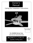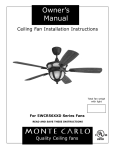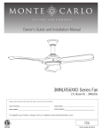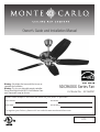
1
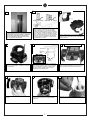
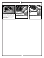
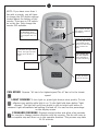
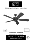
Owner’s Guide and Installation Manual
Warning: Only blades that come with the fan are accepatable for installation.
Warning: This fan uses dimmable remote controller.
Do not install light kit with SBCFL (Self-Ballasted Compact Fluorescent Lamp) on this fan.
5DCR60XX Series Fan
UL Model No. : AC-560DC
Attach sales receipt to this card and retain as your proof of purchase
DATE OF PURCHASE:
RETAILER NAME:
MODEL NUMBER:
RETAILER ADDRESS:
To register your fixture, please visit our website www.montecarlofans.com
11 kgs
24.2 lbs
Total fan weight
WARNING: TO REDUCE THE RISK OF FIRE, ELECTRIC SHOCK, OR INJURY TO PERSONS, OBSERVE THE FOLLOWING
READ AND SAVE THESE INSTRUCTIONS
Installation work and electrical wiring must be done by qualified person(s) in accordance with applicable codes and standards (ANSI/NFPA
70-1999), including fire-rated construction.
Use this unit only in the manner intended by the manufacturer. If you have any questions contact the manufacturer.
After making the wire connections, the wires should be spread apart with the grounded conductor and the equipment-grounding conductor
on one side of the outlet box and ungrounded conductor on the other side of the outlet box. The splices, after being made, should be
turned upward and pushed carefully up into the outlet box.
WARNING: Before you begin installing the fan, servicing or cleaning unit, Switch power off at Service panel and lock service disconnecting
means to prevent power from being switched on accidentally. When the service disconnecting means cannot be locked, securely fasten a
prominent warning device, such as a tag, to the service panel.
Be cautious! Read all instructions and safety information before installing your new fan. Review the accompanying assembly diagrams.
When cutting or drilling into wall or ceiling, do not damage electrical wiring and other hidden utilities.
Make sure the installation site you choose allows the fan blades to rotate without any obstructions. Allow a minimum clearance of 7 feet
from the floor to the trailing edge of the blade.
WARNING: To Reduce The Risk Of Fire, Electric Shock, or Personal Injury, Mount To Outlet Box Marked “Acceptable for Fan Support of
31.8 kg (70 lbs) or less” And Use Mounting Screws Provided With The Outlet Box.
WARNING: To reduce the risk of personal injury, do not bend blade holders during installation to motor, balancing or during cleaning. Do
not insert foreign object between rotating blades.
Attach the mounting bracket using only the hardware supplied with the outlet box.
WARNING: To reduce the risk of fire or electric shock, this fan must be installed with an isolating wall control/switch.
WARNING: To reduce the risk of fire or electric shock, this fan should only be used with fan speed control part no. BJX1514AST manufactured by Air Cool Industrial Co., Ltd.
WARNING: To reduce the risk of fire or electric shock, do not use this fan with any solid state fan speed control device, or variable speed
control.
If this unit is to be installed over a tub or shower, it must be marked as appropriate for the application.
Never place a switch where it can be reached from a tub or shower.
The combustion airflow needed for safe operation of fuel-burning equipment may be affected by this unit’s operation. Follow the heating
equipment manufacturer’s guideline safety standards such as those published by the National Fire Protection Association (NFPA), and the
American Society for Heating, Refrigeration and Air Conditioning Engineers (ASHRAE) and the local code authorities.
CAUTION: To Reduce the Risk of Electric Shock, Disconnect the electrical supply circuit to the fan before installing the light kit.
All set screws must be checked and tightened where necessary before installation.
Tools Required for Assembly (not included): Electrical Tape, Phillips Screwdriver, Pliers, Safety Glasses,
Stepladder and Wire Strippers.
Cutomer Service
800-969-3347
Customer Service Center
7400 Linder Ave.
Skokie, IL 60077
www.montecarlofans.com
© 2011 Monte Carlo Fan Company
2
4/20/2012
1
Before you begin installing the fan, Switch power off
at Service panel and lock service disconnecting means
to prevent power from being switched on accidentally.
When the service disconnecting means cannot be
locked, securely fasten a prominent warning device,
such as a tag, to the service panel.
4
2
OUTLET BOX METHOD
Warning-Risk of fire, electric shock, or personal injury. The fan in this box may be either
directly supported from a structural framing
member of a building and/or may be mounted
to an outlet box marked acceptable for fan support of of 31.8kg (70 lbs) or less. Most outlet
boxes commonly used for the support of lumminaires may not be acceptable for fan support
and may need to be replaced. Consult a qualified electrician if in doubt.
5
3
Remove Safety bar from mounting bracket by
loosing screws, sliding bar to side, and lifting it
off the 2 screws.
6
BUILDING STRUCTURE METHOD
FAN BRACE AND BOX METHOD
Outlet box
Mounting
Plate
Wood
Screws
Remove the 6 screws attaching the Mounting
neck the mounting plate. Retain the 6 screws
for re-assembly.
Secure mounting plate directly to a joist from
the buliding structure via the two knock out
holes on the outlet box. Use only the appropriate wood screws and washers included with
your fan. Caution: Wood screws must go
through into the building joist.
Install the mounting Plate to approved fan
brace and box combination use only the hardware provided with the fan brace and box.
7
8
9
Lift mounting neck to mounting Plate and align
screws.
Secure mounting neck to the mounting plate
with 6 screws to become a complete mounting bracket.
Remove the keeper pin and cotter pin.
© 2011 Monte Carlo Fan Company
3
4/20/2012
10
Loosen the 2 set screws. You should
be able to put your downrod into the
yoke.
13
Tighten both yoke set screws to further secure downrod. Reinstall the
downrod ball previously removed.
16
Carefully lift fan assembly onto
mounting bracket. Rotate fan so that
the notch on the ball engages the
ridge in the mounting bracket. This
will allow hands-free wiring.
© 2011 Monte Carlo Fan Company
12
11
Install canopy and yoke cover over
the downrod. Thread wire through
downrod with canopy and yoke cover
assembled.
Insert downrod into motor yoke.
Next, insert clevis pin through yoke
and downrod and secure with cotter
pin.
14
15
Install the two thumbscrews to
secure the yoke cover. Tighten
securely.
17
Remove the shipping stabilizers
and discard.
18
Hang assembled fan from the mounting bracket
installed to ceiling in previous step. Make sure
the fan is hanging straight. Rotate fan until the
tab on the Mounting bracket engages the slot
on the Downrod Ball. This must be done to
prevent the fan body from rotating when the
blades are in motion.
4
Re-install safety bar removed in step.
3 by placing safety bar on screws,
sliding into place, and tightening the
2 screws.
4/20/2012
19
Safety cable installation
21
20
Black
Safety Cable
White
Lag Screw
Green
safety
cable
lock
washer
For Canadian installation and for USA fan and
light kit combinations over 35 lbs, in both flush
and downrod mode the safety cable must be
installed into the house structure beams using
the 3” lag screws,washers, and lock washers.
provided. Make sure that when the safety cable
is fully extended the leadwires are longer than
the cable and no stress is placed on the leadwires.
22
Loosen one and remove one preassembled screw from mounting bracket. Save
screw. Lift canopy up, aligning its keyhole
slot with the preassembled screw on
mounting bracket and twist clockwise to
lock in place. Re-install the removed
screw and tighten all screws securely.
25
Install 3 screws and washers per
blade and tighten securely. Repeat
for all 5 blades.
© 2011 Monte Carlo Fan Company
Fan
Black
White
Green(downrod)
Green(Bracket)
washer
3” lag
screw
House
Make wire connections to power source using
wire nuts provided. Make sure that no filiments
are outside of the wirenut. After making the
wire connections, the wires should be spread
apart with the grounded conductor and the
equipment-grounding conductor on one side of
the outlet box and ungrounded conductor on
the other side of the outlet box.
23
Make sure that all exposed wiring is
secured inside wire nuts. Note: Wires
from house may vary in color and
may not include ground wire. After
wiring is conplete, gently push wires
into junction box with wire nuts
pointing upward. Refer to point 3 of
safety tips.
24
Place the gasket onto the blade
bracket as shown above.
26
Warning: Only blades that come
with the fan are accepatable for
installation.
Place blade onto blade bracket with
gasket.
27
Attach blade assembly to motor
using the motor screws and washers
provided. Tighten screws securely.
5
Loosen 2 screws and remove 1 screw
and save.
4/20/2012
28
Install the switch housing plate by
aligning the 2 screws with the 2 key
slot holes on the plate and twist to
lock into place. Install the 1 screw
removed and tighten the other 2
screws securely.
© 2011 Monte Carlo Fan Company
29
30
Remove the 3 screws on the switch
housing plate and save.
6
Install the switch housing using the
three screws previously removed.
4/20/2012
Receiver learning function (dc motor)
After the fan is powered (DC motor), the receiver will start sourcing the frequency in the first 30 seconds; during the time, any instruction from the transmitter (pressing any button) will be recognized and
memorized as the ID frequency of the using transmitter; frequencies from the other transmitters won’t
be identified as the instruction to operate your fan. When the power is off and on again, if the receiver
does not receive the frequency from the transmitter in 30 seconds, receiver will automatically use last
frequency set before the power off.
Setting up the dIp switch: Follow below steps:
1.Cut off power supply (turn off the power switch) to the fan before setting up and matching between
the fan and the transmitter.
2.Then set/change the DIP switch on the transmitter wanted to work with the fan.
3.Then re-connect the power supply (turn on) the fan again. If the power is on already, you must
turn the power off first (turn off the power switch) and then turn the power back for learn
function setting.
4.Push any key on transmitter within 30 second (Keep pusing the key for at least 3 seconds), the
fan will match and set up with the transmitter.
5.Repeat the above steps for the other set of fans and transmitters in the house.
Special note:
1.If there is a power failure, and you have more than one fan inside the house, do not push the transmitter within 60 seconds, otherwise the transmitter signal will be picked up by all fans and the fans cannot be controlled separately.
2.The fan can remember the running setting before power failure or cut off.
3.If the new fan runs after connected to power, it may be due to the fan remembering the previous
running setting in the factory during the QC process, push “stop” key on transmitter twice to stop.
Operation & Installation:
1. Remove the battery cover and the battery from the transmitter, you will see 4 dipswitches with on/off
printing, adjust the dipswitches with your own choice (different combinations).
2. Power your fan, use the transmitter to send the signal to the receiver by pressing any button on the
transmitter, the receiver will memorize the frequency from the transmitter as the ID signal from now.
3. Refer to page 8 for remote control transmitter features.
Tips for end users:
1. Once the power is off from last using and you want to restart your fan, in case there are two fans or
more in your house with the same transmitter and receiver set, REMEMBER to wait for 60 seconds
before using the transmitter, otherwise it will cause a transmitter to control both fans in the same time.
2. Receiver has the memory function, fan will automatically return to the previous setting before power
off.
3. If your fan is operated automatically after installation, it is because your fan still memorize the previous setting at factory, just simply press the “stop” button on the transmitter twice to stop your fan.
4. When fan is turned on or operated forward/reverse function, it shutters & goes back & forth until it
turns. It is a normal performance of this fan and it will take for few seconds to run this operation.
5. If fan or light isn't working, reset the power ( turn power off and then turn it back ) and redo the
learn function.
© 2011 Monte Carlo Fan Company
7
4/20/2012
NOTE: If you have more than 1
fan with a remote, you will have
to change the DIP switch settings
located above the battery of the
remote. There are no DIP switches on the fan. Only change the
remote DIP switches.
LIGHT DELAY
FAN REVERSE (Press
once to change direction
of the fan)with fan running.
When the low battery
sign is shown on the
LCD display, replace a
new battery.
Memory for fan speed.
Press "M", fan will run
at the speed as last
setting if it was turned
off by remote controller
Pressing the light delay button activates the light delay
function. The light will automatically shut off after 1
minute.
LIGHT ON/OFF SETTING AND DIMMER
(Press and hold to
dim light infinitively)
Fan speed control
FAN OFF SETTING
(Turns fan off only)
FAN SPEED Depress “#1 bar is for highest speed.The #7 bar is for the lowest
speed.
LIGHT DIMMER To turn light on, press light dimmer once quickly. To turn
offpress once quickly while light is on. To dim light hold down button “light
dimmer”. The light will cycle from bright to dim to bright until button is
released. Light willmaintain last setting if turned off. You can see the percentage
on the display screen.
FORWARD/REVERSE Depress reverse button and allow a few seconds
for remote to change rotation direction with fan running. The fan will come to
a complete stop and then run in the opposite direction. This process may take
20-30 seconds.
© 2011 Monte Carlo Fan Company
8
4/20/2012
Trouble Shooting
If you have difficulty operating your new ceiling fan, it may be the result of incorrect assembly, installation,
or wiring. In some cases, these installation errors may be mistaken for defects. If you experience any faults,
please check this Trouble Shooting Chart. If a problem cannot be remedied, or you are experiencing difficulty
in installation, please call our Customer Service Center at the number printed on your parts list insert sheet.
Warning: Before servicing or cleaning unit, Switch power off at Service panel and lock service disconnecting means to prevent power from being switched on accidentally. When the service disconnecting means cannot be locked, securely fasten a prominent warning device, such as a tag,
to the service panel.
1. If fan does not
start:
1.Check main and branch circuit fuses or circuit breakers.
2.Check line wire connections to fan and switch wire connections in switch housing.
3.Check learn function setting.
cauTIOn: Make sure main power is turned off.
2. If fan sounds noisy: 1.Check to make sure all screws in motor housing are snug (not over tightened).
2.Check to make sure the screws which attach the fan blade holder to the motor are tight.
3.Check to make sure wire nut connectors in switch housing are not rattling against each
other or against the interior wall of the switch housing.
cauTIOn: Make sure main power is turned off before entering switch housing.
4.Some fan motors are sensitive to signals from Solid State variable speed controls. dO nOT
uSe a Solid State variable speed control.
5.Allow "break-in" period of 24 hours. Most noises associated with a new fan will disappear
after this period.
3. If fan wobbles:
1.Make sure that the ridge of the canopy engages the notch in the downrod ball.
2.Check that all blades are screwed firmly into blade holders.
3.Check that all blade holders are tightened securely to motor.
4.Make sure that canopy and mounting bracket are tightened securely to ceiling junction box
and junction box is mounted firmly to ceiling joist.
5.Most fan wobble problems are caused when blade levels are unequal. Check this level by
selecting a point on the ceiling above the tip of one of the blades. Measure this distance from
blade tip to ceilng. Keeping measure within 1/8", rotate the fan until the next blade is positioned for measurement. Repeat for each blade. If all blade levels are not equal, you can
adjust blade levels by the following procedure. To adjust a blade tip down, insert a washer
(not supplied) between the blade and blade holder at the screw closest to the motor. To
adjust a blade tip up, insert washer (not supplied) between the blade and blade holder at the
two screws farthest from the motor. Reverse the position of the washer if blades mount from
top of blade.
6.If blade wobble is still noticeable, interchanging two adjacent (side by side) blades can
redistribute the weight and possibly result in smoother operation.
4. If light does not
work:
1.Check
2.Check
3.Check
4.Check
5.Check
wire from fan to make sure it is connected to hot wire from house.
for loose or disconnected wires in fan switch housing.
for loose or disconnected wires in light kit.
for faulty light bulbs.
learn function setting.
cauTIOn: Make sure main power is turned off before entering switch housing.
Warning: Only blades that come with the fan are accepatable for installation.
Warning: This fan uses dimmable remote controller. do not install light kit
with SBcFL (Self-Ballasted compact Fluorescent Lamp) on this fan.
© 2011 Monte Carlo Fan Company
9
4/20/2012
Apr.2012 New format
Sep.5.2012 update about learn function setting