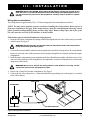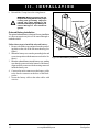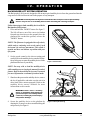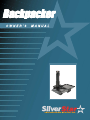
1
Backpacker
SAFETY
GUIDELINES
The symbols below are used throughout this owner's manual and on the product to identify warnings and
important information. It is very important for you to read them and understand them completely.
WARNING! Failure to follow designated procedures can cause either personal injury,
component damage, or malfunction (black symbol on yellow triangle with black border).
MANDATORY! These actions should be performed as specified. Failure to perform
mandatory actions can cause injury to personnel and/or damage to equipment (white
symbol on blue dot with white border).
PROHIBITED! These actions should be prohibited. These actions should not be performed
at any time or in any circumstances. Performing a prohibited action can cause injury to
personnel and/or damage to equipment (black symbol with red circle and red slash).
Please fill out the following information for quick reference:
Pride Provider:_____________________________________________________________________
Address:__________________________________________________________________________
Phone Number: ___________________
Purchase Date:____________________
Serial Number:_________________________________
NOTE: This owner’s manual is compiled from the latest specifications and product information available at the time of publication. We reserve the right to make changes as they become necessary. Any
changes to our products may cause slight variations between the illustrations and explanations in this
manual and the product you have purchased.
Copyright © 2006
Pride Mobility Products Corp.
INFMANU3109/Rev B/April 2006
This product is manufactured by:
Silver Star Mobility
578 Mason Way
Medford, Oregon 97501
www.pridemobility.com
Backpacker
C O N T E N T S
I.
INTRODUCTION......................................................................................................................... 4
II.
SAFETY ......................................................................................................................................... 6
III. INSTALLATION .......................................................................................................................... 8
IV.
OPERATION ............................................................................................................................... 13
V.
BATTERY CHARGING ........................................................................................................... 15
VI. CARE AND MAINTENANCE ................................................................................................ 16
VII. TROUBLESHOOTING ............................................................................................................ 18
VIII. SPECIFICATIONS ................................................................................................................... 19
IX. WARRANTY................................................................................................................................ 20
Backpacker
www.pridemobility.com
3
I .
INTRODUCTION
Welcome to Pride Mobility Products Corporation (Pride). Congratulations on the purchase of your new
Backpacker Lift System. The Backpacker Lift System design combines the most advanced state-of-the-art
components with modern, attractive styling. We are certain that the design features and trouble-free operation
will add convenience to your daily living and ensure complete satisfaction.
At Pride, your safety is important to us. Please read and follow all instructions in this manual before
operating your lift system for the first time. These instructions were produced for your benefit. Your
understanding of these instructions is essential for the safe operation of your new lift system.
Pride is not liable for damage to property or personal injury arising out of the unsafe use of a Backpacker
Lift System. Pride is also not liable for any property damage or personal injury arising out of the failure of
any person and/or user to follow the instructions and recommendations set forth in this manual or any other
instructions or recommendations contained in other Backpacker Lift System related literature issued by
Pride or contained on the Backpacker Lift System itself.
INTERNET AND PRIVATE PURCHASES
If you purchased your product over the internet or from a previous owner and you have any questions about
the safe use and/or maintenance of the product, please visit Pride’s web site www.pridemobility.com or
contact your authorized Pride Provider.
PURCHASER’S AGREEMENT
By accepting delivery of this product, you promise that you will not change, alter, or modify this product or
remove or render inoperable or unsafe any guards, shields, or other safety features of this product; fail,
refuse, or neglect to install any retrofit kits from time to time provided by Pride to enhance or preserve the safe use
of this product.
INFORMATION EXCHANGE
We want to hear your questions, comments, and suggestions about this manual. We would also like to hear
about the safety and reliability of your new lift system, and about the service you received from your
authorized Pride Provider.
Please notify us of any change of address, so we can keep you apprised of important information about
safety, new products, and new options that can increase your ability to use and enjoy your new lift system.
Please feel free to contact us at the address below:
Pride Mobility Products Corporation
Attn.: Customer Care Department
182 Susquehanna Ave.
Exeter, PA 18643-2694
[email protected]
800.424.8205
NOTE: If you ever lose or misplace your product registration card or your copy of this manual, contact
us and we will be glad to send you a new one immediately.
4
www.pridemobility.com
Backpacker
I .
INTRODUCTION
PRIDE OWNERS CLUB
As an owner of a Pride product, you are encouraged to enroll in the Pride Owners Club. Complete and
return your enclosed product registration card or visit Pride’s web site at www.pridemobility.com. As a
registered member, each time you visit our site, you have access to the most interactive, educational venue
available today for people with mobility needs, their families, and friends.
From our home page, select “Owners Club” to enter a page dedicated to current and potential Pride product
owners. You will gain access to interviews, stories, recreation ideas, daily living tips, product and funding
information, and interactive message boards. These message boards invite you to communicate with other
Pride customers as well as Pride representatives who are available to assist you with any questions or
concerns you may have.
Backpacker
www.pridemobility.com
5
II.
SAFETY
PRODUCT SAFETY SYMBOLS
The symbols below are used on the lift system to identify warnings, mandatory actions, and prohibited
actions. It is very important for you to read and understand them completely.
Crush Hazard—Pinch/crush points created during assembly and operation.
Keep hands clear.
Crush Hazard—Moving parts can crush and cut. Keep hands clear.
Crush Hazard—Moving lift can crush. Keep feet clear during operation.
Do not sit on Power Chair or
Scooter while activating lift
or during transport.
Do not sit on mobility device while activating lift or during transport.
Read and follow the information in the owner’s manual.
Maximum lifting capacity.
DW
R
1234L004 R EV
A
Do not use as a step.
Lift system intended for use with unoccupied mobility device. Do not use
product to lift people.
Removal of grounding prong can create electrical hazard. If necessary,
properly install an approved 3-pronged adapter to an electrical outlet having
2-pronged plug access. Failure to heed could result in personal injury and/
or property damage.
Prevent personal injury and equipment damage. Do not connect an extension
cord to the charger cord.
6
www.pridemobility.com
Backpacker
II.
SAFETY
LIFTING CAPABILITIES
The Backpacker Lift System is designed for a maximum lifting capacity of 325 lbs. (147 kg). Under no
circumstances should the Backpacker Lift System be made to exceed this weight limit. Subjecting the lift
system to the strain of hoisting more than it is designed to lift may cause it to fail, resulting in damage to the
mobility device and/or the lift operator. Refer to the mobility device owner’s manual for information on the
overall weight of the mobility device before lifting.
WARNING! Adding accessories, oversize batteries, or a different seat will increase the
weight of your mobility device. Verify with your authorized Pride Provider that the total
weight of your mobility device, including additions, does not exceed 325 lbs. (147 kg).
INSTALLATION
Your Backpacker Lift System is an inside van lift designed for installation into various brands of full-sized and mini
vans. Read and fully understand the installation instructions provided in this manual and related literature for your
brand of vehicle before installing the lift system.
LIFTING NON-PRIDE PRODUCTS
The Backpacker Lift System is an extremely versatile device which users may employ to lift items other than Pride
products. Pride has no control over such use, nor can Pride anticipate every possible use to which a Backpacker
Lift System may be put. Lifting non-Pride products with the Backpacker Lift System is done at the operator’s own
risk, and Pride accepts no liability for damage or injury resulting from such use.
PRELIFT INSPECTION
Before operating the Backpacker Lift System, conduct a careful survey of your surroundings to ensure that
the lift system has a clear path of operation. Remove any possible obstructions before operating the lift and
do not allow children to operate or play near the lift.
OPERATOR POSITIONING
The operator of the lift should stand a safe distance from the unit being lifted/lowered to ensure that his/her
feet are never positioned under the raised lift platform. The operator should also keep his/her hands clear of
the lift system to avoid the potential for injury.
TRANSPORT VEHICLE POSITIONING
Be sure your vehicle is parked on flat, level ground before attempting to load, lift, or remove a mobility
device with the Backpacker Lift System. Make sure the vehicle emergency park brake is engaged before
loading or unloading a mobility device.
Backpacker
www.pridemobility.com
7
III.
INSTALLATION
BACKPACKER LIFT SYSTEM INSTALLATION
WARNING! Prevent product and/or vehicle damage! The Backpacker Lift should be installed
by an authorized service technician only.
NOTE: Use only the supplied hardware to install the Backpacker Lift System.
NOTE: If you are installing the Backpacker into a full-sized van, refer to the information provided in
separate literature for side-entry securement system installation. If you are installing the Backpacker
into a mini van, refer to the following information.
Follow these steps to install the Backpacker:
1. Remove the rear seat from the van according to the vehicle manufacturer removal instructions.
2. Route the Backpacker wiring harness through the vehicle. See “Wiring Harness Installation.”
WARNING! Prevent product damage! Route the wiring harness through the vehicle rather
than under the vehicle to avoid coming in contact with sharp edges, extreme temperatures,
moving parts, and roadway debris. Power shorts may occur if wires come in contact with
hot exhaust parts or sharp edges.
WARNING! Never attach the wiring harness to a secondary power source. Do not attempt
to use trailer wiring to power the lift system. The wiring harness must be connected
directly to the vehicle battery.
NOTE: If your lift is equipped with an optional onboard battery, refer to “Onboard Battery Installation.”
3. Position a securement system floor plate over each
set of floor locks that hold the rear seat to the
floor of the van. See figure 1.
FLOOR PLATE
MID-RISER BAR
NOTE: Securement systems vary depending on
vehicle manufacturer. While these instructions
describe basic installation for most vehicles,
your securement system may require separate
parts based on the make of your vehicle. Refer
to the installation instructions supplied with
your securement system or contact your authorized Pride Provider for more information.
4. Secure each floor plate to the floor of the van
using the supplied mounting hardware. See figure
1. Do not fully tighten the mounting hardware at
this time.
5. Position the mid-riser bar over the floor plate
closest to the rear of the vehicle, aligning the
mounting holes in the mid-riser bar with those in
the floor plate. See figure 1.
8
MOUNTING HARDWARE
Figure 1. Basic Securement System Installation
www.pridemobility.com
Backpacker
III.
INSTALLATION
TOWER MICROSWITCHES
STOP BLOCK
TRUCK
FRAME
LOCKING PLATE
TRUCK MICROSWITCH
Figure 2. Backpacker Installation
6. Remove the shipping cleat from the Backpacker stop block and discard it and the mounting nut.
7. Install the bolt you removed from the shipping cleat into the stop block on the Backpacker and secure with the
supplied nut. See figure 2.
8. Connect the Backpacker wiring harness to the hand control.
9. Place the Backpacker up on blocks, so that there is at least 1-foot of clearance under the frame.
10. Connect the Backpacker to a power source.
11. Reach under the Backpacker truck frame and simultaneously press the microswitch and the “UP” button on
the hand control to raise the tower 4-6 in. See figure 2.
12. Carefully slide the Backpacker into the rear of the van and center it over the threaded holes in the floor plates.
See figure 2. Make sure the mid-riser bar is still properly aligned.
WARNING! Lifting weight beyond your physical capability can result in personal injury. At
least two people should lift the Backpacker into the rear of the vehicle.
WARNING! Avoid pinch points! Do not hold the lift frame by the pivot points when installing
the Backpacker.
13. Place a locking plate over each of the threaded holes in the floor plate and secure with the supplied bolts. Screw
the bolts into the threaded holes, but do not fully tighten the hardware at this time. See figure 2.
Backpacker
www.pridemobility.com
9
III.
INSTALLATION
14. Simultaneously press the two microswitches on the
Backpacker tower arm and the “DOWN” button
on the hand control until the tower reaches its full
extension. See figure 2.
15. Release the microswitches, then press the “UP” button on the hand control to retract the tower arm.
16. Insert the T-Bar into the lift tower and secure into
position with the supplied hardware. See figure 3.
17. Push the “UP” button on the hand control to raise the
platform frame to its highest position.
18. Inspect the clearance between the bumper and the
platform frame. Appropriate clearance is necessary in
order to slide the platform into the vehicle.
NOTE: If there is not adequate clearance between
the bumper and the platform frame, you may need
to install an end support bracket. Remove the Backpacker from the van and install the end support
bracket close to the rear door opening. Reinstall the
lift into the van, making sure that the bolts protruding from the bottom plate of the Backpacker closest
to the van door snap into the tapped holes on the
top of the end support bracket, then repeat steps 13
through 18.
LIFT TOWER
T-BAR
Figure 3. T-Bar Installation
NOTE: It may be required to trim the rear inside
sill to achieve the adequate platform clearance with
the platform under load.
19. Attach the lift platform to the lift frame. Refer to the
installation instructions supplied with your lift platform.
20. Drape the Y-strap over the platform and secure the
lock assembly to the lift platform. See figure 4.
21. Fully tighten all mounting hardware throughout the lift
system once the unit has been centered and all required clearances have been achieved.
22. Run the Backpacker through an entire lift cycle. Lower
the platform to the ground and then raise the platform
to the fully stowed position in the van. See IV.
“Operation.”
LOCK ASSEMBLY
Figure 4. Y-Strap Installation
NOTE: Pay attention to the path of the lift platform during operation. Make sure the lift does not rub
against or interfere with the vehicle in any way. If you notice any contact between the lift platform and
the vehicle, stop lift operation immediately and contact your authorized Pride Provider for assistance.
10
www.pridemobility.com
Backpacker
III.
INSTALLATION
WARNING! Release the “DOWN” button when the lift platform touches the ground. Do not
allow the motor to run after the lift platform has touched the ground. Allowing the motor to
run will increase the pressure on the lift platform and may result in product or vehicle
damage.
Wiring Harness Installation
The wiring harness is approximately 25 ft. (7.62 meters) long and will accommodate most vehicles.
NOTE: You may wish to perform a practice run before installing the wiring harness. Route a piece of
light rope (equivalent to the gage of the wiring harness) along the anticipated path observing contact
points, potential rubbing/chafing points, and any sharp edges. Remove sharp edges with a fine grade
file, then treat the steel with a rust inhibitor or metal sealant.
Follow these steps to route the Backpacker wiring harness:
1. Route the lift system wiring harness (starting at the lift) through the interior of the vehicle until you reach the
vehicle battery. See figure 5.
WARNING! Avoid routing the wire harness where it will interfere with or become pinched
by the securement system floor plates.
2. Conceal the harness behind or under the interior panels (there should be existing holes). Be certain that the
harness is protected with a rubber grommet when passing it through the metal panels and into the engine
compartment.
3. Inside the engine compartment, secure the harness to the firewall and the inner fender with plastic wire ties. Use
care not to cause abrasions to the wiring harness. It is important to secure the wiring harness at various points
along its run of the vehicle.
WARNING! Do not cut or shorten the wiring harness. If the harness is too long, coil the
excess wire and secure it with plastic wire ties.
4. Remove the 15-amp fuse from the wiring harness. See figure 5.
5. Connect the red wire to the positive (+) terminal and the black (grounding) wire to the negative (-) terminal
of the vehicle battery.
HAND CONTROL
GROUNDING WIRE
FUSE
WIRING HARNESS
VEHICLE BATTERY
LIFT WIRING CONNECTION
Figure 5. Wiring Harness Installation
Backpacker
www.pridemobility.com
11
III.
INSTALLATION
6. Reinstall the 15-amp fuse to the wiring harness.
WARNING! Before operating the lift,
inspect the wiring harness for proper
routing and grounding. Improper
routing can cause damage to the
harness, and improper grounding can
cause damage to the electrical
system.
PROTRUDING BOLTS
Onboard Battery Installation
The optional onboard battery is designed for easy installation
as it does not require any wires to be routed through or
under the vehicle.
Follow these steps to install the onboard battery:
1. Remove the rubber caps and nuts from the protruding bolts on the side of the lift motor housing. See
figure 6.
2. Mount the battery case onto the protruding bolts and
secure into position with the nuts removed earlier. See
figure 6.
3. Insert the onboard battery into the battery case, making
sure that the connector on the bottom of the battery
aligns and fully connects with the mating connector
inside the battery case.
4. Connect the male connector on the battery cable
to the female connector at the base of the Backpacker.
5. Secure the battery cable to the other cables with
wire ties.
12
Figure 6. Onboard Battery Installation
www.pridemobility.com
Backpacker
I V.
OPERATION
BACKPACKER LIFT SYSTEM OPERATION
The Backpacker Lift System is designed to lift an unoccupied mobility device from the ground and into the
cargo area of a full-sized or mini van for the purpose of easy transport.
WARNING! The Backpacker Lift System is intended for the transport of unoccupied mobility
devices only. Do not sit on mobility device while activating lift or during transport.
Follow these steps to load a mobility device with the
Backpacker Lift System:
1. Press and hold the “DOWN” button. See figure 7.
The lift will move out of the van to its farthest
forward stop, then lower to the ground. Once the
platform has reached the ground, release the
“DOWN” button.
NOTE: The lift motor is equipped with a slip clutch,
which emits a ratcheting noise at the end of each
horizontal (in and out) movement. This sound is
normal and does not indicate a problem with your
lift system.
2. Set the speed control to the slowest setting and
carefully drive the mobility device onto the lift platform, being sure to center the mobility device on the
platform to the best of your ability.
Figure 7. Hand Control
NOTE: You may wish to load the mobility device
while standing next to it using the manual freewheel
feature. Refer to the mobility device owner’s manual
for more information on manual freewheel mode.
3. Shut down the power to the mobility device, remove
the key if applicable, and make sure the unit is in
drive mode (drive motors engaged). Refer to the
mobility device owner’s manual for more
information on drive mode.
WARNING! Never leave a mobility
device in freewheel mode during lift
system transport. The mobility device
could roll, resulting in personal injury
and product damage.
4. Secure the mobility device to the platform by
draping the Y-strap over the seat and buckling the
strap securely. See figure 8.
Backpacker
Figure 8. Y-Strap Positioning
www.pridemobility.com
13
I V.
OPERATION
WARNING! Prevent product damage! Never attempt to secure the Y-strap over the seatback
or armrests of the mobility device.
5. Pull the end of the strap tightly to remove any excess slack over the seat.
NOTE: Inspect the Y-strap before each use to ensure there are no signs of fraying or wear. Ensure that
the mobility device is secured properly before transport. Pride is not liable for damage or loss resulting
from improper securing of a mobility device.
6. Press and hold the “UP” button. See figure 7. The lift will move up to its highest lift point, then slide into the van.
Once the mobility device is stowed completely within the van, release the button.
NOTE: Make sure that the van has enough headroom to accommodate the height of the mobility device
before loading it into the van. Lower the tiller, adjust the seatback angle, or remove the seat if necessary.
Refer to the mobility device owner’s manual for more information on these adjustments.
WARNING! Prevent vehicle damage! Do not exceed the load limits of your vehicle as
specified by the vehicle manufacturer.
WARNING! Do not sit on your mobility device while it is in a moving vehicle. Personal
injury and/or property damage may result.
When you are ready to remove the mobility device from the van, lower the platform to the ground, unfasten the
Y-strap, and drive the mobility device off of the platform. Once unloading is complete, return the lift platform
into the van.
14
www.pridemobility.com
Backpacker
V.
BATTERY
CHARGING
BATTERY CHARGING
Follow these steps to charge the onboard battery:
1. Remove the onboard battery from the battery case and place it near a standard electrical wall outlet.
2. Remove the cap from the charger socket located on the bottom of the battery, plug the charger cord into the
charger socket, then connect the charger cord to a standard electrical outlet. See figure 9.
PROHIBITED! Never use an extension cord to plug in your charger cord. Plug the charger
cord directly into a properly wired standard wall outlet.
PROHIBITED! Removal of the grounding prong can create an electrical hazard. If necessary,
properly install an approved 3-pronged adapter to an electrical outlet having 2-pronged
plug access. Failure to heed could result in personal injury and/or property damage.
WARNING! Prevent component damage! Do not attempt to charge the battery and operate
the lift system at the same time.
WARNING! Prevent component damage! Do not attempt to wire the lift system directly to
the vehicle battery if the lift system is equipped with an onboard battery.
NOTE: It is recommended that you replace the battery every 3–5 years. Store the battery in a
moisture-free environment when not in use.
Charger Circuit Fuse
The battery charger cord is equipped with a 7.5A charger
circuit fuse. In the event the fuse should cease to work:
1. Remove the cap from the fuse holder, then pull the
fuse out of its slot.
2. Examine the fuse to be sure it is blown. See figure 10.
3. Insert a new fuse of the same rating.
MAIN CIRCUIT BREAKER
WARNING! The replacement fuse
must exactly match the rating of the
fuse being replaced. Failure to use
properly rated fuses may cause
damage to the electrical system and
may result in personal injury.
Main Circuit Breaker
The main circuit breaker is a safety feature built into your
lift system battery. When the battery and/or motor is heavily
strained (e.g., from excessive loads), the main circuit
breaker trips to prevent damage to the motor and the
electronics. If the circuit trips, allow the lift system to “rest”
for approximately one minute. Then, push in the circuit
breaker button and continue normal operation. If the main
circuit breaker continues to trip repeatedly, contact your
authorized Pride Provider.
CHARGER SOCKET AND CAP
Figure 9. Battery Charging
WORKING FUSE
BLOWN FUSE (REPLACE)
Figure 10. Fuse Replacement
Backpacker
www.pridemobility.com
15
VI.
CARE
AND
MAINTENANCE
CARE AND MAINTENANCE
Your lift system requires a minimal amount of care and maintenance. If you do not feel confident in your
ability to perform the maintenance listed below, you may schedule inspection and maintenance at your
authorized Pride Provider. The following areas require periodic inspection and/or care and maintenance.
90-Day Maintenance Schedule
Every 90 days, remove the battery connections and clean them to ensure uninterrupted electronic connection and grease these pivot points:
! Main screw
! Pivot
Wiring Harness and Hand Control
! The wiring harness should be checked periodically for corrosion and/or decay. Contact your authorized Pride
Provider if the wiring harness needs to be replaced.
! Avoid leaving the hand control in areas where it will be exposed to inclement weather or temperature extremes.
Exposure to the elements may cause damage to the hand control.
Lift Platform/Metal Components
! Check the lift platform for wear or damage. Contact your authorized Pride Provider for repair or replacement.
! The lift platform surface may become slippery if exposed to moisture (ice, snow, rain, mist/spray conditions,
etc.). Use caution when loading/unloading a mobility device in these conditions and wipe off any excess
moisture from the lift platform.
! Regularly inspect the metal lift components for scratches. Treat any problem areas with a rust inhibitor or metal
sealant.
Battery Replacement
WARNING! Battery posts, terminals, and related accessories contain lead and lead
compounds. Wash hands after handling.
Follow these steps to replace the onboard battery (figure 11):
1. Unfasten the battery securement strap located at the bottom of the battery box.
2. Remove the hardware from the battery securement bracket and remove the bracket.
3. Remove the hardware from the battery connector.
4. Slide the battery out of the battery box to expose the battery harness.
5. Disconnect the battery harnesses from the battery terminals.
6. Connect the battery harnesses to the new battery.
7. Slide the new battery into the battery box.
8. Reinstall the hardware to secure the battery connector and tighten.
9. Reinstall the battery securement bracket and tighten the hardware.
10. Refasten the battery securement strap.
If your lift system is exhibiting wear that you feel is questionable in any way, contact your authorized Pride Provider
immediately. Do not attempt to repair, adjust, or modify the manufacturer settings and materials.
16
www.pridemobility.com
Backpacker
VI.
CARE
AND
MAINTENANCE
BATTERY BOX
BATTERY SECUREMENT STRAP
BATTERY SECUREMENT BRACKET
BATTERY CONNECTOR
Figure 11. Battery Replacement
Backpacker
www.pridemobility.com
17
VII.
TROUBLESHOOTING
TROUBLESHOOTING
Any electromechanical device occasionally requires some troubleshooting. However, most of the problems that may arise can usually be solved with a bit of thought and common sense. Many of these problems
occur because the batteries are not fully charged or because the batteries are worn down and can no longer
hold a charge.
What if the motor on my lift system will not operate?
! Make sure the onboard battery or vehicle battery is fully charged.
! Make sure all connections to the motor and battery are secure.
! Check the wiring harness for signs of wear or decay. Replace the harness if necessary.
What if the lift system operates slowly up or down?
! Make sure the onboard battery or vehicle battery is fully charged.
! Make sure all connections to the motor and battery are secure.
! Check the wiring harness for signs of wear or decay. Replace the harness if necessary.
What if the lift platform does not lower completely to the ground?
Check to make sure that the area under the lift platform is free from obstructions.
18
www.pridemobility.com
Backpacker
VIII.
Lift System Dimensions
Total Lift System Weight
Base Lift Weight
Maximum Lift Capacity
Mobility Device Dimensions
Maximum Lift Travel Distance
Motor
Onboard Battery
Charger
SPECIFICATIONS
SPECIFICATIONS
Overall Length: 46 in. (117 cm)
Overall Width (including platform): 47 in. (119.4 cm)
Overall Height: 38 in. (96.5 cm)
Platform Length: 47 in. (119.4 cm)
Platform Width: 27 in. (68.6 cm)
155 lbs. (70 kg) including standard platform
98 lbs. (44.5 kg)
325 lbs. (147 kg)
Length: 47 in. (119.4 cm)*
Height: 34 in. (86.4 cm)*
Width 26 in. (66 cm)
26 in. (66 cm) van floor to ground
Fully sealed, 12-volt DC
12-volt, 18 AH
110-volt, off-board
*Depending on vehicle dimensions.
Backpacker
www.pridemobility.com
19
IX.
WARRANTY
THREE-YEAR TRANSFERABLE LIMITED WARRANTY
For three (3) years from the date of purchase, Pride Mobility Products will repair or replace at our option, free of
charge, any mechanical or electrical component found upon examination by an authorized representative of Pride
to be defective in material and/or workmanship.
This warranty does not extend to those items, which may require replacement due to normal wear and tear.
! Labor, service calls, shipping, and other charges incurred for repair of the product, unless specifically authorized by Pride Mobility Products Corporation IN ADVANCE, are excluded.
Exclusions also include components with damage caused by:
! Contamination
! Abuse, misuse, accident, or negligence
! Battery fluid spillage or leakage
! Commercial use, or use other than normal
! Improper operation, maintenance, or storage
! Repairs and/or modifications made to any part without specific consent from Pride Mobility Products Corporation.
! Circumstances beyond the control of Pride
ONE-YEAR WARRANTY
The battery is covered by a separate one (1) year warranty provided by the battery manufacturer. The batteries
are not warranted by Pride Mobility Products Corporation.
SERVICE CHECKS AND WARRANTY SERVICE
An authorized Pride Mobility Products Provider must perform warranty service. Do not return faulty parts to Pride
Mobility Products without prior written authorization. All transportation costs and shipping damage incurred while
submitting parts for repair or replacement is the responsibility of the purchaser.
Failure to follow the instructions, warnings, and notes in the owner’s manual and those located on your Pride lift
product can result in personal injury or product damage and will void Pride’s product warranty.
There is no other express warranty.
IMPLIED WARRANTIES
Implied warranties, including those of merchantability and fitness for a particular purpose, are limited to one (1)
year from the date of purchase and to the extent permitted by law. Any and all implied warranties are excluded.
This is the exclusive remedy. Liabilities for consequential damages under any and all warranties are excluded.
Some states do not allow limitations on how long an implied warranty lasts or do not allow the exclusion of
limitation incidental or consequential damages. The above limitation or exclusion may not apply to you.
This warranty gives you specific rights, and you may also have other rights, which vary from state to state.
Please fill out and return the product registration card to Pride Mobility Products. This will aid Pride in providing
the best possible technical and customer service.
20
www.pridemobility.com
Backpacker
N OT E S
Backpacker
www.pridemobility.com
21
NOTES
22
www.pridemobility.com
Backpacker
*INFMANU3109*