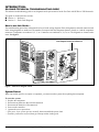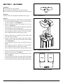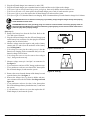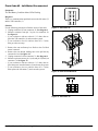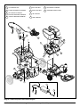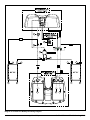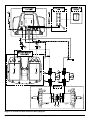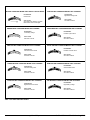
1
SAFETY
GUIDELINES
The symbols below are used throughout this troubleshooting guide to identify warnings and important information. It is very
important for you to read what follows the symbols and understand it completely.
WARNING! Failure to follow designated procedures can cause either personal injury, component damage, or
malfunction (black symbol on yellow triangle with black border).
MANDATORY! These actions should be performed as specified. Failure to perform mandatory actions can cause
injury to personnel and/or damage to equipment (white symbol on blue dot).
PROHIBITED! These actions are prohibited. These actions should not be performed at any time or in any
circumstances. Performing a prohibited action can cause injury to personnel and/or damage to equipment (black
symbol with red circle and red slash).
© Pride Mobility Products Corp. 2006
RevA/October06/INFMANU3424
tents
Table of Contents
Introduction ....................................................................................................................4
Go-Chair Technical Troubleshooting Guide ............................................................................................. 4
How to use this Guide... ..........................................................................................................................4
System Retest .........................................................................................................................................4
Section 1 - No Power......................................................................................................5
Section 2 - Flash Code Diagnosis ................................................................................7
Flash Code - Steady Flash of the Speed/Profile LEDs ....................................................................... 7
Flash Code - Battery Condition Meter LEDs Scroll Left-to-Right ......................................................7
Flash Code #1 - Low Battery Voltage ...................................................................................................7
Flash Code #2 - Left Motor Disconnected ...........................................................................................9
Flash Code #3 - Left Motor Wiring Fault ............................................................................................10
Flash Code #4 - Right Motor Disconnected ......................................................................................11
Flash Code #5 - Right Motor Wiring Fault .........................................................................................12
Flash Code #7 - Possible Joystick Fault ...........................................................................................12
Flash Code #8 - Possible Controller Fault .........................................................................................13
Flash Code #9 - Solenoid Brake Fault ...............................................................................................13
Flash Code #10 - High Battery Voltage ..............................................................................................14
Go-Chair Technical Troubleshooting Guide
www.pridemobility.com
3
INTRODUCTION:
GO-CHAIR TECHNICAL TROUBLESHOOTING GUIDE
This technical troubleshooting guide covers diagnostic and repair scenarios for the Go-Chair with PG Drives VSI electronics.
This guide is divided into two sections:
! Section 1 — No Power
! Section 2 — Flash Code Diagnosis
How to use this Guide...
The troubleshooting procedures in the manual are keyed to the wiring diagrams. Each wiring harness and each connector used
in the wiring diagrams are numbered. The numbers correspond with the component (harness, board, etc.) and the component
connector. Components are numbered 1, 2, 3, etc. Connectors are numbered 1a, 2a, 3a, etc. The diagrams are located on the
insert. See figure 1.
Use Diagram Insert for Reference
2b
(+)
( )
(+)
50A
Figure 1. Reference Diagram Insert
System Retest
When a procedure specifies to replace a component, you must retest the system after replacing that component.
To retest the system:
1. Replace the component.
2. Reconnect any harnesses that were disconnected.
3. Reconnect the batteries (if disconnected).
4. Power on the controller.
5. Operate the seat or power base.
— If the power chair system operates normally, then reassemble the power chair.
— If another problem has surfaced, then go to that procedure in this guide.
4
www.pridemobility.com
Go-Chair Technical Troubleshooting Guide
SECTION 1 - NO POWER
Symptoms:
! The batteries are fully charged.
! All electrical components are connected correctly.
! The on/off key is pressed and the power does not come on.
Diagnosis:
The power has been interrupted somewhere in the system.
Figure 2. Connector 1a
Solution:
Use the following procedure to find the source of the interruption:
1. Locate the off-board charging socket (1a) on the front of
the VSI controller (1). See diagram 1.
2. Measure voltage across pin 1 (B+) and pin 2 (B-) on connector 1a. See figure 2.
— If your multimeter indicates about 25VDC, then replace the
VSI controller (1) and retest the system.
— If your multimeter indicates 0VDC, then go to the next step.
— If your multimeter indicates 18VDC or less (but not 0VDC),
then recharge the batteries and retest the system.
3. Remove the battery box from the Go-Chair. Refer to the
Go-Chair owner’s manual.
4. Measure voltage across the negative and positive battery
contact pads (5e and 6d) on the underside of the battery
box. See diagram 2.
— If your multimeter indicates more than 18VDC, then go to
step 9.
— If your multimeter indicates 18VDC or less (but not 0VDC),
then recharge the batteries and retest the system.
— If your multimeter indicates 0VDC, then go to the next step.
5. Remove the hardware from the bottom of the battery box
and open the battery box. See figure 3.
6. Measure voltage across the two outermost battery terminals. See figure 4.
— If your multimeter indicates more than 0VDC, then replace
the battery contact pads (5d, 5e, and 6d) and retest the system.
— If your multimeter indicates 0VDC, then go to the next step.
Figure 3. Battery Box Disassembly
+
-
+
-
Figure 4. Outermost Battery Terminals
Go-Chair Technical Troubleshooting Guide
www.pridemobility.com
5
7. Measure resistance across the two inside battery terminals.
See figure 5.
— If your multimeter indicates less than 1 ohm, then replace
the batteries (5 and 6) and retest the system.
— If your multimeter indicates more than 1 ohm, then go to
the next step.
+
-
+
-
WARNING! Battery posts, terminals, and related
accessories contain lead and lead compounds.
Wash hands after handling.
WARNING! Always protect the batteries from
freezing and never charge a frozen battery.
Charging a frozen battery may result in personal
injury and/or damage to the battery.
Figure 5. Innermost Battery Terminals
M A N DATO RY ! R E D ( + ) c a b l e s mu s t b e
connected to positive (+) battery terminals/
posts. BLACK (-) cables must be connected to
negative (-) battery terminals/posts. Failure to
connect the battery cables and harnesses in
the proper manner may result in personal injury
and/or damage to the power chair. REPLACE
cables immediately if damaged.
8. Measure resistance across pin 1 and pin 2 of the circuit
breaker (4e). See figure 6.
— If your multimeter indicates less than 1 ohm, then replace
the off-board charger/battery breaker harness (3) and retest
the system.
— If your multimeter indicates more than 1 ohm, then replace
the circuit breaker (4e) and retest the system.
less than 1 ohm
Figure 6. Circuit Breaker (4e)
7
8
7
6
5
3
4
3
4
1
2
1
2
5
(from step 4)
9. Place the battery box back onto the Go-Chair. Refer to the
Go-Chair owner’s manual.
10. Unplug connector 1b from connector 2a. See diagram 1.
11. Measure voltage from pin 6 (B+) to pin 8 (B-) and from pin
7 (B-) to pin 5 (B+) on connector 2a. See figure 7.
— If your multimeter indicates more than 18VDC, then replace the VSI controller (1) and retest the system.
— If your multimeter indicates less than 18VDC, then replace
the power interface harness (2) and retest the system.
6
www.pridemobility.com
9
8
9
6
Figure 7. Connector 2a
Go-Chair Technical Troubleshooting Guide
SECTION 2 - FLASH CODE DIAGNOSIS
Flash Code - Steady Flash of Speed/Profile LEDs
Symptom:
Steady Flash of Speed/Profile LEDs
Diagnosis:
This is an indication of the “LOW ENABLE, NO DRIVE AWAY” feature set up on the VSI controller. This feature keeps the
unit from driving while an onboard battery charger is plugged into an electrical outlet. This feature is not applicable to this
model as the Go-Chair uses an off-board charger only.
Solution:
— If the VSI controller indicates a low enable, no drive away fault, then replace the VSI controller (1) and retest the system.
Flash Code - Battery Condition Meter LEDs Scroll Left-to-Right
Symptoms:
Battery Condition Meter LEDs Scroll Left-to-Right
Diagnosis:
This is an indication of the “INHIBIT ACTIVE” feature set up on the VSI controller. This feature keeps the Go-Chair from
driving while the off-board charger is plugged into the VSI controller.
Solution:
— If the VSI controller indicates an inhibit active fault and there is no off-board charger plugged into connector 1a, then
replace the VSI controller (1) and retest the system.
Flash Code #1 - Low Battery Voltage
Symptoms:
One Red Battery Condition Meter LED Flashing
Diagnosis:
The battery voltage to the VSI controller is low. This is most likely due to batteries that are not getting charged properly
or at all. The VSI controller will indicate this fault when the voltage to the VSI is lower than 22 volts.
Solution:
Use the following procedure to find the source of the fault:
1. Measure voltage across pin 1 (B+) and pin 2 (B-) on connector 1a. See figure 8.
— If your multimeter indicates less than 22VDC and the chair
is charged through the joystick, then go to the next step.
— If your multimeter indicates less than 22VDC and the chair
is charged through the battery box, then go to step 4.
— If your multimeter indicates more than 22VDC, then replace the VSI controller (1) and retest the system.
Go-Chair Technical Troubleshooting Guide
Figure 8. Connector 1a
www.pridemobility.com
7
2.
3.
—
—
—
—
Plug the off-board charger into connector 1a on the VSI.
Plug the off-board charger into a standard electrical outlet and observe the lights on the charger.
If the power light on the off-board charger does not light up, then verify that the electrical outlet is live.
If the electrical outlet is live, then replace the off-board charger power cord (10) and retest the system.
If the power light is green, then replace the off-board charger (9) and retest the system.
If the power light is red, then the batteries are charging. Pride recommends that you let the batteries charge for 8-14 hours.
PROHIBITED! Never use an extension cord to plug in your battery charger. Plug the charger directly into a properly
wired standard electrical outlet.
PROHIBITED! Removal of the grounding prong can create an electrical hazard. If necessary, properly install an
approved 3-pronged adapter to an electrical outlet having 2-pronged plug access. Failure to heed could result in
personal injury and or property damage.
(from step 1)
4. Remove the battery box from the Go-Chair. Refer to the
Go-Chair owner’s manual.
5. Plug the off-board charger into the off-board charger port
on the battery box (connector 3a), then plug the off-board
charger into an electrical outlet.
6. Measure voltage across the negative and positive battery
contact pads (5e and 6d) on the underside of the battery
box. See diagram 2.
— If the voltage increases from the reading in step 1, then the
batteries are charging. Pride recommends that you let the
batteries charge for 8-14 hours.
— If the voltage decreases or stays the same as the reading in
step 1, then go to the next step.
2
1
3
Figure 9. Connector 3a
less than 1 ohm
7. Measure voltage across pin 1 and pin 2 on connector 3a.
See figure 9.
— If your multimeter indicates 0VDC, then go to the next step.
— If your multimeter indicates more than 0VDC, then replace
the off-board charger (9) and retest the system.
Figure 10. Fuse 3g
8. Remove the screws from the bottom of the battery box and
open the battery box. See figure 3.
9. Remove the charger fuse (3g) from its holder and measure resistance across the fuse blades. See diagram 2 and
figure 10.
— If your multimeter indicates less than 1 ohm, then replace
the off-board charger/battery breaker harness (3) and retest
the system.
— If your multimeter indicates an open, then replace the offboard charger (9) and retest the system.
8
www.pridemobility.com
Go-Chair Technical Troubleshooting Guide
Flash Code #2 - Left Motor Disconnected
Symptoms:
Two Red Battery Condition Meter LEDs Flashing
7
5
Diagnosis:
There is a communication problem between the left motor (7)
and the VSI controller (1).
Solution:
Use the following procedure to find the source of the fault:
1. Unplug connector 1b from connector 2a. See diagram 1.
2. Measure resistance from pin 3 to pin 4 on connector 2a.
See figure 11.
— If your multimeter indicates about 0.5-1.5 ohms, then replace the VSI controller (1) and retest the system.
— If your multimeter does not indicate about 0.5-1.5 ohms,
then go to the next step.
3. Remove the seat and battery box. Refer to the Go-Chair
owner’s manual.
4. Remove the rear shroud, making sure not to pull out any
connected wires. See figure 12.
5. Unplug connector 2e from connector 7a. See diagram 1.
6. Measure resistance across pin 1 (red) and pin 2 (black) on
connector 7a. See figure 13.
— If your multimeter indicates about 0.5-1.5 ohms, then replace the power interface harness (2) and retest the system.
— If your multimeter does not indicate about 0.5-1.5 ohms,
then replace the left motor (7) and retest the system.
8
9
6
3
4
1
2
Figure 11. Connector 2a
Figure 12. Rear Shroud Removal
Figure 13. Connector 7a
Go-Chair Technical Troubleshooting Guide
www.pridemobility.com
9
Flash Code #3 - Left Motor Wiring Fault
Symptoms:
Three Red Battery Condition Meter LEDs Flashing
Diagnosis:
There is a wiring fault between the left motor (7) and brake
(7b). This can indicate a wiring problem between the motor
and the brake or possibly a short from the motor to the most
negative battery terminal (one side of each brake).
Solution:
Use the following procedure to find the source of the fault:
1. Unplug connector 1b from connector 2a. See diagram 1.
2. Measure resistance from pin 3 to pin 9 and pin 3 to pin 7 on
connector 2a. See figure 14.
— If your multimeter indicates an open for each test, then replace the VSI controller (1) and retest the system.
— If your multimeter indicates a short or a relatively low resistance (less than 1M ohm) for either test, then go to the
next step.
3. Remove the seat and battery box. Refer to the Go-Chair
owner’s manual.
4. Remove the rear shroud, making sure not to pull out any
connected wires. See figure 12.
5. Unplug connector 2e from connector 7a. See diagram 1.
6. Measure resistance from pin 1 (red) to pin 4 (white) then
from pin 1 (red) to pin 5 (white) on connector 7a. See
figure 15.
— If your multimeter indicates an open for each test, then replace the power interface harness (2) and retest the system.
— If your multimeter indicates a short or a relatively low resistance (less than 1M ohm) for either test, then replace the
left motor (7) and retest the system.
10
www.pridemobility.com
7
5
8
7
6
5
9
8
6
9
3
4
3
4
1
2
1
2
Figure 14. Connector 2a
Figure 15. Connector 7a
Go-Chair Technical Troubleshooting Guide
Flash Code #4 - Right Motor Disconnected
7
Symptoms:
! Four Battery Condition Meter LEDs Flashing
! Three Red LEDs and One Yellow LED
5
Diagnosis:
There is a communication problem between the right motor (8)
and the VSI controller (1).
Solution:
Use the following procedure to find the source of the fault:
1. Unplug connector 1b from connector 2a. See diagram 1.
2. Measure resistance across pin 1 and pin 2 on connector 2a.
See figure 16.
— If your multimeter indicates about 0.5 - 1.5 ohms, then replace the VSI controller (1) and retest the system.
— If your multimeter does not indicate about 0.5 - 1.5 ohms,
then go to the next step.
3. Remove the seat and battery box. Refer to the Go-Chair
owner’s manual.
4. Remove the rear shroud, making sure not to pull out any
connected wires. See figure 12.
5. Unplug connector 2d from connector 8a. See diagram 1.
6. Measure resistance across pin 1 (red) and pin 2 (black) on
connector 8a. See figure 17.
— If your multimeter indicates about 0.5-1.5 ohms, then replace the power interface harness (2) and retest the system.
— If your multimeter does not indicate about 0.5-1.5 ohms,
then replace the right motor (8) and retest the system.
Go-Chair Technical Troubleshooting Guide
8
9
6
3
4
1
2
Figure 16. Connector 2a
Figure 17. Connector 8a
www.pridemobility.com
11
Flash Code #5 - Right Motor Wiring Fault
Symptoms:
! Five Battery Condition Meter LEDs Flashing
! Three Red LEDs and Two Yellow LEDs
7
5
8
7
6
5
9
Diagnosis:
There is a wiring fault between the right motor (8) and brake (8b).
Solution:
Use the following procedure to find the source of the fault:
1. Unplug connector 1b from connector 2a. See diagram 1.
2. Measure resistance from pin 1 to pin 9 and pin 1 to pin 7 on
connector 2a. See figure 18.
— If your multimeter indicates an open for each test, then replace the VSI controller (1) and retest the system.
— If your multimeter indicates a short or a relatively low resistance (less than 1M ohm) for either test, then go to the
next step.
3. Remove the seat and battery box. Refer to the Go-Chair
owner’s manual.
4. Remove the rear shroud, making sure not to pull out any
connected wires. See figure 12.
5. Unplug connector 2d from connector 8a. See diagram 1.
6. Measure resistance from pin 1 (red) to pin 4 (white), then
from pin 1 (red) to pin 5 (white) on connector 8a. See
figure 19.
— If your multimeter indicates an open for each test, then replace the power interface harness (2) and retest the system.
— If your multimeter indicates a short or a relatively low resistance (less than 1M ohm) for either test, then replace the
right motor (8) and retest the system.
8
6
9
3
4
3
4
1
2
1
2
Figure 18. Connector 2a
Figure 19. Connector 8a
Flash Code #7 - Possible Joystick Fault
Symptoms:
! Seven Battery Condition Meter LEDs Flashing
! Three Red LEDs and Four Yellow LEDs
Diagnosis:
! The VSI controller (1) has a problem with the joystick (gimble).
! The joystick was out of the neutral (center) position when powered up. The battery condition meter LEDs will ripple sideto-side twice, then display seven flashing LEDs.
NOTE: If the battery condition meter is showing seven flashing LEDs, make sure there is no physical damage to the
joystick keeping it from returning to the neutral (center) position.
Solution:
Use the following procedure to correct the fault:
1. Turn the VSI off. Make sure the joystick is not being depressed in any directions.
2. Turn the VSI back on.
— If the VSI still displays this fault, replace the VSI controller (1) and retest the system.
12
www.pridemobility.com
Go-Chair Technical Troubleshooting Guide
Flash Code #8 - Possible Controller Fault
Symptoms:
! Eight Battery Condition Meter LEDs Flashing
! Three Red LEDs, Four Yellow LEDs, and One Green LED
Diagnosis:
This is an indication that there is a problem with the VSI controller.
— If this fault occurs, replace the VSI controller (1) and retest
the system.
7
5
8
7
6
5
9
8
6
9
3
4
3
4
1
2
1
2
Figure 20. Connector 2a
Flash Code #9 - Solenoid Brake Fault
Symptoms:
! Nine Battery Condition Meter LEDs Flashing
! Three Red LEDs, Four Yellow LEDs, and Two Green LEDs
Diagnosis:
There is a communication problem between the motor brakes
and the VSI controller (1).
NOTE: This fault will occur if either motor is in freewheel
mode at start up. Make sure both freewheel levers are in the
drive position before starting up your Go-Chair. Refer to the
Go-Chair owner’s manual for more information.
Figure 21. Connectors 7a and 8a
Solution:
Use the following procedure to find the source of the fault:
1. Unplug connector 1b from connector 2a. See diagram 1.
2. Measure resistance across pin 9 and either pin 7 or pin 8
on connector 2a. See figure 20.
— If your multimeter indicates about 30 ohms, then replace
the VSI controller (1) and retest the system.
— If your multimeter indicates an open, then go to the next
step.
3. Remove the seat and battery box. Refer to the Go-Chair
owner’s manual.
4. Remove the rear shroud, making sure not to pull out any
connected wires. See figure 12.
5. Unplug connector 2d from connector 8a and connector 2e
from connector 7a. See diagram 1.
6. Measure resistance across pin 3 (yellow) and pin 6 (yellow) on connectors 7a and 8a. See figure 21.
— If your multimeter indicates less than 1 ohm for both readings, then go to the next step.
— If your multimeter indicates an open for either reading,
then replace the corresponding brake (7b or 8b) and retest
the system.
Go-Chair Technical Troubleshooting Guide
www.pridemobility.com
13
7. Measure resistance across pin 4 (white) and pin 5 (white)
on connectors 7a and 8a. See figure 22.
— If your multimeter indicates about 60 ohms for each test,
then replace the power interface harness (2) and retest the
system.
— If your multimeter does not indicate about 60 ohms for
either test, then replace the corresponding brake (7b or
8b) and retest the system.
Flash Code #10 - High Battery Voltage
Figure 22. Connectors 7a and 8a
Symptoms:
! Ten Battery Condition Meter LEDs Flashing
! Three Red LEDs, Four Yellow LEDs, Three Green LEDs
Diagnosis:
The total battery voltage is over 32VDC. This only appears if the output of the charger is over 32VDC.
Solution:
Use the following procedure to find the source of the fault:
NOTE: Make sure the only chargers used on the Go-Chair are Pride Mobility chargers. All of Pride’s chargers are “smart
chargers,” meaning when the batteries are fully charged the charger stops charging them. If a non-Pride charger was
used, the batteries may be overcharged.
1. Remove the battery box. Refer to the Go-Chair owner’s manual.
2. Plug the off-board charger into the off-board charger port (connector 3a) on the battery box. See diagram 2.
3. Measure voltage across the positive and negative battery contact pads (5e and 6d) on the underside of the battery box. See
diagram 2.
— If your multimeter indicates less than 32VDC, then replace the VSI controller (1) and retest the system.
— If your multimeter indicates more than 32VDC, then replace the off-board charger (9) and retest the system.
14
www.pridemobility.com
Go-Chair Technical Troubleshooting Guide
1
VSI CONTROLLER
5
LEFT BATTERY
9
OFF-BOARD CHARGER
2
POWER INTERFACE HARNESS
6
RIGHT BATTERY
10
CHARGER POWER CORD
3
OFF-BOARD CHARGER/
BATTERY BREAKER HARNESS
7
LEFT MOTOR
4
CIRCUIT BREAKER HARNESS
8
RIGHT MOTOR
1
1b
2a
2
3
1a
4
5b
3f
4c
5
6
5a
3e
6b
6a
4d
2c
2b
8b
7b
2e
8
2d
7a
8a
7
10a
9
9a
10
10b
Diagram 1. Main Component Connection Diagram
Go-Chair Technical Troubleshooting Guide
www.pridemobility.com
3g
3a
3d
3c
3b
4e
4b
3e
4a
3f
4c
4d
+
+
-
-
+
6a
6b
5a
6d
5d
5b
5e
Diagram 2. Go-Chair 2-D Battery Box Wiring Diagram
www.pridemobility.com
Go-Chair Technical Troubleshooting Guide
6c
5c
2a
+
2b
2c
2e
6d
5e
2d
8a
7a
8b
7b
Diagram 3. Go-Chair 2-D Rear Electronics Wiring Diagram
Go-Chair Technical Troubleshooting Guide
www.pridemobility.com
BATTERY CONDITION METER LEDs SCROLL LEFT-TO-RIGHT
DIAGNOSIS
Inhibit Active
SOLUTION
See Flash Code - Battery Condition
Meter LEDs Scroll Left-to-Right.
ONE BATTERY CONDITION METER LED FLASHING
DIAGNOSIS
Low Battery Voltage
SOLUTION
See Flash Code #1.
TWO BATTERY CONDITION METER LEDs FLASHING
DIAGNOSIS
FIVE BATTERY CONDITION METER LEDs FLASHING
DIAGNOSIS
Right Motor Wiring Fault.
SOLUTION
See Flash Code #5
SEVEN BATTERY CONDITION METER LEDs FLASHING
DIAGNOSIS
Possible Joystick Fault
SOLUTION
See Flash Code #7.
EIGHT BATTERY CONDITION METER LEDs FLASHING
DIAGNOSIS
Left Motor Disconnected
Possible Controller Fault
SOLUTION
SOLUTION
See Flash Code #2.
THREE BATTERY CONDITION METER LEDs FLASHING
DIAGNOSIS
See Flash Code #8.
NINE BATTERY CONDITION METER LEDs FLASHING
DIAGNOSIS
Left Motor Wiring Fault
Solenoid Brake Fault.
SOLUTION
SOLUTION
See Flash Code #3.
FOUR BATTERY CONDITION METER LEDs FLASHING
DIAGNOSIS
See Flash Code #9.
TEN BATTERY CONDITION METER LEDs FLASHING
DIAGNOSIS
Right Motor Disconnected.
High Battery Voltage.
SOLUTION
SOLUTION
See Flash Code #4.
See Flash Code #10.
Table 1. Go-Chair VSI Flash Codes
www.pridemobility.com
Go-Chair Technical Troubleshooting Guide
Pride Mobility Products Corporation
182 Susquehanna Ave.
Exeter, PA 18643
Contact Information
Main Toll Free Number
Local Phone Number
800.800.8586
570.655.5574
Internet Address for Product Information
Internet Address for Service Information
“Live Chat” available 8:30 — 5:00 EST
www.pridemobility.com
www.prideservice.com
Toll Free Service Hotline
877.800.1248 (Dealers Only)
Press 7 for Technical Service, then
Press 1 for Help Desk or
Press 2 for Quantum Rehab Tech or
Press 3 for Power Chair Tech or
Press 4 for Scooter Tech or
Press 5 for Lift Chair Tech
Parts Order Fax
866.800.1011
Technical Assistance is available Monday — Friday 8:30 a.m. — 7:00 p.m. EST*
*Skeleton Staff from 5:30 p.m. — 7:00 p.m.