1
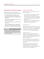
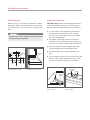
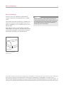
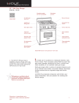
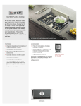
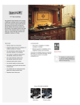
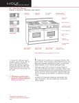
INSTALLATION GUIDE
Pro Ventilation Hood Liners
Contents
Important Note
Wolf Pro Hood Liners. . . . . . . . . . . . . . . . . . . . . . . . . . . 3
To ensure the safe and efficient use of Wolf equipment,
please take note of the following types of highlighted
information throughout this guide:
Installation Considerations . . . . . . . . . . . . . . . . . . . . . . 4
Pro Hood Liner Specifications . . . . . . . . . . . . . . . . . . . 5
Pro Hood Liner Installation . . . . . . . . . . . . . . . . . . . . . . 7
IMPORTANT NOTE highlights information that is especially
important.
Service Information . . . . . . . . . . . . . . . . . . . . . . . . . . . 11
CAUTION signals a situation where minor injury or product
damage may occur if instructions are not followed.
Features and specifications are subject to change at any time
without notice. Visit wolfappliance.com/specs for the most
up-to-date information.
WARNING states a hazard that may cause serious injury or
death if precautions are not followed.
IMPORTANT NOTE: Throughout this guide, dimensions in
parentheses are millimeters unless otherwise specified.
Wolf Pro Hood Liners
3
wolfappliance.com/specs
Pro Hood Liner Installation
IMPORTANT NOTE: This installation must be completed
by a qualified installer or Wolf factory certified service.
Wolf Pro Hood Liner
Read this entire installation guide and blower installation
instructions prior to installation and save for the local
inspector’s reference. The homeowner should keep this
installation guide for future reference.
Serial Number
This appliance must be installed in accordance with
National Electrical Codes, as well as all state, municipal
and local codes. The correct voltage, frequency and
amperage must be supplied to the appliance from a dedicated, grounded circuit which is protected by a properly
sized circuit breaker or time delay fuse. The proper
voltage, frequency and amperage ratings are listed on the
product rating plate.
Record the model and serial numbers before installing the
hood liner. Both numbers are listed on the product rating
plate, located inside the left wall of the hood liner shell.
Refer to the illustration below.
RATING PLATE
Location of rating plate
(inside hood).
Model Number
Installation Considerations
IMPORTANT INSTRUCTIONS
TO REDUCE THE RISK OF FIRE, ELECTRIC
SHOCK OR INJURY, OBSERVE THE FOLLOWING:
• Installation work and electrical wiring must be
done by qualified person(s) in accordance with all
applicable codes and standards, including fire-rated
construction.
• Two installers are recommended due to the size and
weight of the pro hood liner.
• Install the pro hood liner only with a blower manufac-
tured by Wolf.
4
Installation Considerations
Wolf pro hood liners are recommended for use with all
Wolf cooking appliances.
• Proper installation is the responsibility of the installer.
Product failure due to improper installation is not
covered under the Wolf warranty. Refer to the Wolf pro
ventilation hoods use & care guide for warranty details,
or visit the contact & support section of our website,
wolfappliance.com.
• Warranty service must be performed by Wolf factory
certified service. Wolf is not responsible for service
required to correct a faulty installation.
• When cutting or drilling into wall or ceiling, do not
damage electrical wiring and other hidden utilities.
• Ducted fans must always be vented to the outdoors.
To reduce the risk of fire and properly exhaust air,
be certain to duct air outside. Do not vent exhaust
air into spaces within walls or ceilings or into attics,
crawl spaces or garages.
DECORATIVE HOODS
The bottom edge of the decorative hood can not extend
below the hood liner. The bottom 3/4" (19) of the hood liner
is stainless steel. The remaining reveal is galvanized metal.
Verify the decorative hood does not extend beyond 3/4"
(19) to ensure the most visually appealing installation.
BLOWER ASSEMBLIES
Wolf pro hood liners are shipped without a blower
assembly. Internal, in-line and remote blowers are available through your authorized Wolf dealer. For local dealer
information, visit the find a showroom section of our
website, wolfappliance.com.
Blower size is dependant on the size of the cooking
surface, volume of air being moved and length of the duct
run. Refer to ventilation recommendations in the Wolf
design guide.
In-line and remote blowers require a Romex® (not
provided) from the blower to the ventilation hood.
For blower installation, refer to specific instructions
provided with each blower. Additional information can also
be found on our website, wolfappliance.com.
Pro Hood Liner Specifications
5
wolfappliance.com/specs
Overall Dimensions
PRO HOOD LINERS
12"
WIDTH MINUS 6" (152)
3" (76)
(305)
3" (76)
12" (305)
4" (102)
191/4" (489)
22 1/2" (572)
34 3/8" (873), 40 3/8" (1026), 46 3/8" (1178)
52 3/8" (1330), 58 3/8" (1483) WIDTHS
DEPTHS
Installation
PRO HOOD LINERS
ELECTRICAL
LOCATION
DECORATIVE HOOD
HOOD LINER
E
121/2"
75/8"
(318)
(194)
12" (305)
LINER HEIGHT
LINER WIDTH
FOR 191/4"
31" (787) TO 36" (914)
FOR 22 1/2"
30" (762) TO 36" (914)
191/4" (489)
LINER DEPTH
22 1/2" (572)
LINER DEPTH
SIDE VIEW
Pro Hood Liner Specifications
6
Discharge Specifications
Electrical Requirements
The illustration below provides dimensions critical for
proper installation of the pro hood liner. Dimension A in the
illustration will vary with the width of the hood liner. Refer
to the chart below.
Wolf pro hood liners require a separate, grounded 120 V
AC, 60 Hz power supply. The service should have its own
15 amp circuit breaker. Locate the electrical supply within
the shaded area shown in the installation illustration on the
previous page.
In-line and remote blowers require a Romex® (not
provided) from the blower to the ventilation hood.
Pro Hood Liners
HOOD LINER WIDTH
A
34 3/8" (873)
40 3/8" (1026)
46 3/8" (1178)
52 3/8" (1330)
58 3/8" (1483)
14 3/16" (378)
17 3/16" (437)
20 3/16" (513)
23 3/16" (589)
26 3/16" (665)
IMPORTANT NOTE: You must follow all National Electrical
Code regulations. In addition, be aware of local codes and
ordinances when installing your service.
Risk of electrical shock. This hood must be properly
grounded. Electrical service for the hood must be
installed by a qualified electrician in accordance with
all applicable national and local electrical codes.
2" (54)
6" (152)
A
Hood liner discharge.
Pro Hood Liner Installation
7
wolfappliance.com/specs
Install Ductwork
PRO HOOD LINERS
To reduce the risk of fire, use only metal ductwork.
10" (254) round, rigid metal duct is recommended for pro
hood liners.
A straight, short run is most effective and will ensure
proper operation. For best results, duct run should not
exceed 50' (15 m). For runs exceeding 50' (15 m), a higher
CFM blower may be required to maintain proper air flow
and performance. A remote blower installed on a short
duct run may increase the potential for noise.
Internal and in-line blowers require a roof or wall cap (not
provided). Connect ductwork to the cap and work back
towards the hood liner. Use sheet metal screws and
aluminum tape or high temperature duct tape to seal joints
between ductwork sections.
All pro hood liners include a backdraft damper in the transition assembly. Local codes may require the use of an
additional backdraft and/or make-up air damper. Contact
your local HVAC professional for specific requirements.
Backdraft and make-up air dampers are available through
your authorized Wolf dealer. For local dealer information,
visit the find a showroom section of our website,
wolfappliance.com.
DUCTWORK INSTALLATION
THROUGH ROOF
DECORATIVE HOOD
12"
12" (305)
LINER HEIGHT
(305)
4" (102)
FOR 191/4"
31" (787) TO 36" (914)
FOR 22 1/2"
30" (762) TO 36" (914)
191/4" (489)
LINER DEPTH
22 1/2" (572)
LINER DEPTH
Pro Hood Liner Installation
8
Wall Preparation
Hood Liner Preparation
Minimum 2" (51) x 4" (102) lumber is required to construct
wall framing. Refer to the illustration below for mounting
hole locations and a cross-section view of a typical installation.
IMPORTANT NOTE: Remove all packaging material from
hood liner and damper. Failure to remove material will
obstruct airflow and significantly decrease performance.
Framing must be able to support the weight of the hood
and internal blower, if applicable.
1) To remove filters, press upward then rotate bottom
outward. Refer to the illustration below. To aide in
removal, remove center filter first. Gloves should be
worn when handling filters.
2) The damper is packaged inside the hood liner in a
separate box. Remove damper from box and place it
on top of the hood liner using the hold-down brackets.
3) Secure hold-down brackets to damper flange with
screws provided. Refer to the illustration below.
2"
2 3/4"
(51)
(70)
DECORATIVE
HOOD
#10 x 2" (51)
SCREW
8"
4"
(203)
(102)
Mounting hole locations.
4) Seal with aluminum tape or high temperature duct
tape.
5) Connect damper to duct using sheet metal screws and
aluminum tape or high temperature duct tape. Verify
screws do not affect the operation of the damper.
HOLD-DOWN
BRACKET
Installation cross-section.
DAMPER
SPRING
LOWER
CHANNEL
FILTER
SIDE VIEW
Filter removal.
Mount damper.
Pro Hood Liner Installation
9
wolfappliance.com/specs
Hood Liner Installation
Position the hood liner in the desired location. Insert #10 x
2" (59) screws through the mounting holes on the back
plate. Verify the screws engage two wall studs or blocking.
Electrical Connection
Before making electrical connections, make sure the
electrical power is turned off at the service panel.
If additional support is required, drill supplementary holes
through the back plate and secure with screws.
IMPORTANT NOTE: Refer to specific installation instructions provided with each blower assembly for additional
mounting and wiring instructions.
1) Remove the electrical box cover from inside the hood
liner. Insert Romex® from service panel (and Romex®
from in-line or remote blower, if applicable) through the
back of the hood liner and into the electrical box.
Secure with an appropriate electrical connector. Refer
to the illustration below.
2) Use wire connectors provided to connect black to
black, white to white and green to green/bare wire. For
in-line and remote blowers, attach the cord assembly
to Romex® from the blower.
3) Place all wiring connections inside the electrical box
and reinstall electrical box cover. Verify all wires are
secure and not pinched between cover.
4) Insert cord assembly plug into hood liner receptacle.
Refer to the illustration below. Turn on power and
check operation.
ELECTRICAL BOX
(INSIDE HOOD)
Location of electrical box.
RECEPTACLE
(INSIDE HOOD)
Location of receptacle.
Pro Hood Liner Installation
10
Complete the Installation
Troubleshooting
FILTER INSTALLATION
IMPORTANT NOTE: If the pro hood liner does not operate
properly, follow these troubleshooting steps:
To install filters, press upward then rotate bottom outward.
The filter vanes should be placed perpendicular to the
front of the hood. Refer to the illustration below. To aide in
removal, remove center filter first. Gloves should be worn
when handling filters.
LIGHT BULB INSTALLATION
A suction-cup-style light bulb changer is provided with
pro hood liners. Use the changer to push the bulb into the
receptacle and rotate counterclockwise one-quarter turn.
Refer to the illustration below.
SPRING
LOWER
CHANNEL
FILTER
SIDE VIEW
Filter installation.
LIGHT BULB
CHANGER
Light bulb installation.
• Verify electrical power is supplied to the appliance.
• Verify all packaging material has been removed.
• If the appliance does not operate properly, contact
Wolf factory certified service. Do not attempt to repair.
Wolf is not responsible for service required to correct a
faulty installation.
Service Information
11
Service Information
If service is necessary, maintain the quality built into
your pro hood liner by contacting Wolf factory certified
service.
For the name and number of Wolf factory certified service
nearest you, check the contact & support section of our
website, wolfappliance.com or call Wolf customer care at
800-222-7820.
Before servicing or cleaning, switch power off at the
service panel and lock the service disconnecting means
to prevent power from being switched on accidentally.
If it cannot be locked, securely fasten a prominent
warning tag, to the service panel.
When calling for service, you will need the model and
serial numbers of the hood liner. This information is found
on the product rating plate, located inside the left wall of
the hood liner shell. Refer to the illustration below.
RATING PLATE
Location of rating plate
(inside hood).
The information and images in this guide are the copyright property of Wolf Appliance, Inc. Neither this guide nor any information or images contained herein
may be copied or used in whole or in part without the express written permission of Wolf Appliance, Inc. ©Wolf Appliance, Inc. all rights reserved.
Wolf, Wolf & Design, Wolf Gourmet, W & Design and the color red as applied to knobs are registered trademarks and service marks of Wolf Appliance, Inc.
Sub-Zero, Sub-Zero & Design, Dual Refrigeration, Constant Care and The Living Kitchen are registered trademarks and service marks of Sub-Zero, Inc.
(collectively, the “Company Marks.”) All other trademarks or registered trademarks are property of their respective owners in the United States and other countries.
WOLF APPLIANCE, INC.
P. O. BOX 44848 MADISON, WI 53744
821558 REV-B
8/ 2012
WOLFAPPLIANCE.COM
800.222.7820