1
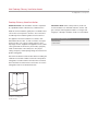
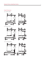
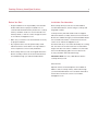
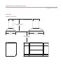
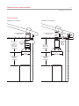
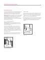
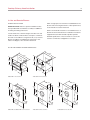
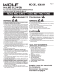
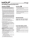
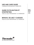
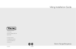
INSTALLATION GUIDE
Cooktop Chimney Ventilation Hoods
Contents
Important Note
Wolf Cooktop Chimney Ventilation Hoods . . . . . . . . . . 3
To ensure the safe and efficient use of Wolf equipment,
please take note of the following types of highlighted
information throughout this guide:
Cooktop Chimney Hood Specifications . . . . . . . . . . . . 4
Cooktop Chimney Hood Installation . . . . . . . . . . . . . 10
Service Information . . . . . . . . . . . . . . . . . . . . . . . . . . . 18
Features and specifications are subject to change at any time
without notice. Visit wolfappliance.com/specs for the most
up-to-date information.
IMPORTANT NOTE: Throughout this guide, dimensions in
parentheses are millimeters unless otherwise specified.
IMPORTANT NOTE highlights information that is especially
important.
CAUTION signals a situation where minor injury or product
damage may occur if instructions are not followed.
WARNING states a hazard that may cause serious injury or
death if precautions are not followed.
Wolf Cooktop Chimney Ventilation Hoods
3
wolfappliance.com/specs
Cooktop Chimney Hood Installation
IMPORTANT NOTE: This installation must be completed
by a qualified installer or Wolf factory certified service.
Read this entire installation guide prior to installation and
save for the local inspector’s reference. The homeowner
should keep this installation guide for future reference.
This appliance must be installed in accordance with
National Electrical Codes, as well as all state, municipal
and local codes. The correct voltage, frequency and
amperage must be supplied to the appliance from a dedicated, grounded circuit which is protected by a properly
sized circuit breaker or time delay fuse. The proper
voltage, frequency and amperage ratings are listed on the
product rating plate.
Record the model and serial numbers before installing the
ventilation hood. Both numbers are listed on the product
rating plate, located inside the left wall of the hood shell,
above the filter. The filter must be removed to access the
rating plate. Refer to the illustration below.
RATING PLATE
Location of rating plate.
(inside hood).
IMPORTANT NOTE: Wolf cooktop chimney hoods are
recommended for use with Wolf induction, electric and
gas cooktops and integrated modules. For ranges and
rangetops, a Wolf pro ventilation hood is recommended.
Wolf Cooktop Chimney Hood
Model Number
Serial Number
Cooktop Chimney Hood Specifications
4
Overall Dimensions
30" (762) WALL HOOD
18" (457)
12"
(305)
4 1/2" (114)
min
30 1/2" (775)
TO
48 1/2" (1232)
19 1/8" (486)
6"
(152)
6 7/8"
(175)
30" (762)
21" (533)
1 9/16"
(40)
36" (914) WALL HOOD
18" (457)
12"
(305)
4 5/16" (110)
min
32 11/16" (830)
TO
50 7/8" (1292)
19 1/8" (486)
8 11/16"
(221)
9 1/4"
(235)
35 7/16" (900)
21" (533)
1 9/16"
(40)
42" (1067) ISLAND HOOD
18" (457)
12"
(305)
5" (127)
min
33 9/16" (853)
TO
19 5/16" (491)
47 1/16" (1195)
12"
(305)
9 1/4"
(235)
42" (1067)
27" (686)
1 9/16"
(40)
Cooktop Chimney Hood Specifications
5
wolfappliance.com/specs
Hood Placement
Wolf cooktop chimney wall and island hoods come with a
telescopic chimney flue that allows you to reach a ceiling
height of 8' (2.4 m) to 9' (2.7 m) with a finished look. A flue
extension to accommodate 10' (3 m) ceilings is available
through your authorized Wolf dealer. For local dealer information, visit the find a showroom section of our website,
wolfappliance.com.
Cooktop Chimney Hoods
FLUE EXTENSION
MINIMUM
MAXIMUM
CTWH30
30 1/2" (775)
48 1/2" (1232)
CTWH36
32 5/8" (829)
50 7/8" (1292)
IH4227
33 1/2"
47" (1194)
Installation of the cooktop chimney hood should be
24" (610) to 30" (762) from the bottom of the hood to the
countertop. To determine placement of the hood, you
must calculate the height of the telescopic chimney flue.
The minimum and maximum flue extension for each
cooktop chimney hood is listed in the chart.
Both sections of the telescopic chimney flue must be
installed in order for the chimney to be lifted for service.
D
A
MINIMUM
FLUE
EXTENSION
C
IMPORTANT NOTE: 8' (2.4 m) ceilings may not permit
installation of the wall or island hood at 30" (762) above the
countertop.
CALCULATE CHIMNEY FLUE HEIGHT
B
A) Height from finished floor to finished ceiling. 8' (2.4 m)
or 9' (2.7 m) ceilings are typical.
B) Height from finished floor to countertop. A 36" (914)
countertop height is standard.
C) Hood mounting height (bottom of hood to countertop).
Dimension C must be between 24" (610) and 30" (762).
8' (2.4 m) ceilings may not allow the maximum 30" (762)
hood mounting height.
D) Calculate chimney flue height: D = A – (B + C).
Dimension D must be between the minimum and
maximum flue extension listed in the chart. Refer to the
illustration.
Hood placement.
(851)
Cooktop Chimney Hood Specifications
6
Before You Start
Installation Considerations
• Proper installation is the responsibility of the installer.
Product failure due to improper installation is not
covered under the Wolf warranty. Refer to the cooktop
chimney ventilation hoods use & care information for
warranty details, or visit the contact & support section
of our website, wolfappliance.com.
Wolf cooktop chimney hoods are recommended for
use with Wolf induction, electric and gas cooktops and
integrated modules.
• Make sure you have the tools and materials necessary
for proper installation.
• Any required service must be performed by a Wolf
authorized service center. Wolf is not responsible for
service required to correct a faulty installation.
• Wolf cooktop chimney hoods are shipped without the
blower assembly. Internal, in-line and remote blowers
are available through your authorized Wolf dealer.
Cooktop chimney wall and island hoods are shipped
without the blower assembly. Internal, in-line and remote
blowers are available through your authorized Wolf dealer.
For local dealer information, visit the find a showroom
section of our website, wolfappliance.com.
The blower will vary in size and is dictated by the cooking
unit, the volume of air that needs to be moved and the
length of the duct run. Refer to ventilation recommendations in the Wolf design guide. These hoods have an
8" (203) round duct with vertical discharge.
IMPORTANT NOTE: Use only a Wolf blower with the
cooktop chimney hood.
BACKSPLASH
Optional stainless steel backsplashes are available in
widths to match cooktop chimney wall hoods through
your authorized Wolf dealer. For local dealer information,
visit the find a showroom section of our website,
wolfappliance.com.
Cooktop Chimney Hood Specifications
7
wolfappliance.com/specs
Electrical Requirements
Wolf cooktop chimney hoods require a separate, grounded
120 V AC, 60 Hz power supply. The service should have its
own 15 amp circuit breaker.
Locate the electrical supply within the shaded area shown
in the installation illustration for your specific model on the
following pages.
For wall hoods, allow a minimum of 12" (305) Romex® wire
from the electrical supply location on the wall for wiring
connections. For the island hood, allow a minimum of
6' (1.8) Romex® wire from the electrical supply location on
the ceiling for wiring connections.
IMPORTANT NOTE: You must follow all National Electrical
Code regulations. In addition, be aware of local codes and
ordinances when installing your service.
Cooktop Chimney Hood Specifications
8
Installation
CHIMNEY WALL HOODS
9"
301/2" (775) TO 481/2" (1232)
OR
(229)
LOCATION OF
ELECTRICAL
3211/16" (830) TO 507/8" (1292)
6"
(152)
HEIGHT OF HOOD
E
4" (102)
30" (762) OR 35 7/16" (900)
21" (533)
DEPTH OF HOOD
WIDTH OF HOOD
24" (610) TO 30" (762)
TO COUNTERTOP
SIDE VIEW
FRONT VIEW
Cooktop Chimney Hood Specifications
9
wolfappliance.com/specs
Installation
CHIMNEY ISLAND HOOD
LOCATION OF ELECTRICAL
THROUGH TOP OF HOOD
33 9/16" (853) TO 47 1/16" (1195)
HEIGHT OF HOOD
42" (1067)
WIDTH OF HOOD
27" (686)
DEPTH OF HOOD
24" (610) TO 30" (762)
TO COUNTERTOP
SIDE VIEW
FRONT VIEW
Cooktop Chimney Hood Installation
10
Install Ductwork
To reduce the risk of fire, use only metal ductwork.
IMPORTANT NOTE: Cooktop chimney ventilation hoods
must exhaust to the outdoors.
An 8" (203) round duct is recommended for cooktop
chimney hoods. Use only rigid metal ductwork, do not use
flex ducting.
Decide where the ductwork will run between the wall hood
and the outside. A straight, short duct run will allow the
hood to perform most efficiently. Limit the number of
elbows and transitions. The duct run should be no longer
than 50' (15 m). There is a possibility of noise issues, if a
remote blower is used with a short duct run.
Wolf recommends installing a backdraft damper in all
installations. A backdraft damper is included with the
hood. It is built into the transition from the hood to the
duct run. In cold weather installations a backdraft damper
is necessary to minimize the backflow of cold air into the
room.
Unless you are using a remote blower, a roof or wall cap
must be installed. Connect ductwork to the cap and work
back towards the hood. Use duct sealing tape to seal
joints between ductwork sections. Refer to the illustrations
on the following page.
Local building codes may require the use of make-up air.
Consult your local HVAC professional for specific requirements in your area.
IMPORTANT NOTE: Consult a qualified HVAC engineer for
specific ducting applications.
To reduce the risk of fire and electric shock, install this
ventilation hood only with a Wolf blower.
Cooktop Chimney Hood Installation
11
wolfappliance.com/specs
Install Ductwork
CHIMNEY WALL HOODS
CHIMNEY ISLAND HOOD
DUCTWORK INSTALLATION
THROUGH ROOF
301/2" (775) TO
48 1/2" (1232)
OR
32 5/8" (829) TO
50 7/8" (1292)
TELESCOPING
HOOD HEIGHT
DUCTWORK INSTALLATION
THROUGH ROOF
DUCTWORK
INSTALLATION
THROUGH
WALL
12"
33 1/2" (851)
TO 47" (1194)
TELESCOPING
HOOD HEIGHT
(305)
DUCTWORK
INSTALLATION
THROUGH
EAVE—
INTERNAL
BLOWER
12"
(305)
21" (535)
HOOD DEPTH
27" (686)
HOOD DEPTH
24" (610) TO 30" (762)
24" (610) TO 30" (762)
BOTTOM OF
HOOD TO
COUNTERTOP
BOTTOM OF
HOOD TO
COUNTERTOP
Cooktop Chimney Hood Installation
12
Wall Hood Installation
Locate the electrical supply for the wall hood through the
wall within the shaded area shown in the illustration on
page 8. Install ductwork as specified on pages 10–11.
IMPORTANT NOTE: If a backsplash is to be used, it should
be installed prior to mounting the wall hood. Secure the
hood mounting brackets to the wall studs prior to
installing the backsplash. Refer to installation instructions
provided with the backsplash.
INSTALL HOOD
Hang the wall hood from the brackets through the rectangular cut-outs on the back of the hood. Refer to the illustration below. The cut-outs are larger than the brackets to
allow for vertical and horizontal adjustment.
Use height adjustment screws to adjust the hood vertically
and the depth adjustment screws to adjust the hood horizontally. Secure the hood with additional mounting
screws.
INSTALL MOUNTING BRACKETS
IMPORTANT NOTE: Wolf recommends that the bottom
of the ventilation hood be installed 24" (610) to 30" (762)
above the countertop.
Construct wall framing that is flush with the interior
surface of the wall studs. Make sure that the framing is
centered in the hood installation location, and that the
height of the framing will allow the mounting brackets to
be secured to the framing within the dimensions shown in
the illustration below.
MOUNTING
BRACKET
RECTANGULAR
CUT-OUT
After the wall surface is finished, secure the mounting
brackets to the framing using the dimensions shown.
Install hood.
FRAMING
(BEHIND DRYWALL)
MOUNTING
BRACKET
71/2"
(190) CTWH30
9 3/8"
(238) CTWH36
Install mounting brackets.
Cooktop Chimney Hood Installation
13
wolfappliance.com/specs
Wall Hood Installation
WIRING CONNECTIONS
ATTACH CHIMNEY FLUE
Electrical connection at the hood:
Use the screws and wall anchors provided to secure the
upper brackets for the chimney flue to the ceiling. Position
the upper brackets based on the dimensions of the
chimney flue. Refer to the illustration below.
1) Remove the cover from the rear electrical box. Remove
the electrical box knockout that faces the hood's
discharge collar.
2) Insert 6" (152) Romex® wire through the knockout
opening. Secure the Romex® wire to the electrical box
with an appropriate connector. Use wire connectors or
wire nuts approved by UL or C/UL.
3) Make electrical connections at the hood. Connect
black to black, white to white and green/yellow to
green or bare wire.
4) Place all wiring connections inside the electrical box
and reinstall the cover. Make sure all wires are secure
and that no wires are pinched between the cover and
electrical box.
Use 8" (203) round metal duct to connect the duct collar
on the hood to the ductwork above. Use duct sealing tape
to make all joints secure and air tight.
Fasten the upper section of the telescopic chimney flue to
the brackets with the screws provided. Refer to the illustration below. Nest the bottom of the chimney flue into the
relief in the hood shell.
SCREWS
UPPER
BRACKET
Refer to page 13–15 for internal blower installation and
remote blower wiring.
Upper brackets.
Chimney flue.
Cooktop Chimney Hood Installation
14
Island Hood Installation
Locate the electrical supply for the island hood through
the ceiling within the dimensions of the chimney flue.
Install ductwork as specified on pages 10–11.
IMPORTANT NOTE: The hood height is 111/4" (286) from
the support frame attachment point.
CONNECT CHIMNEY FLUE
INSTALL SUPPORT SYSTEM
IMPORTANT NOTE: Wolf recommends that the bottom
of the ventilation hood be installed 24" (610) to 30" (762)
above the countertop.
At the island hood installation location, install 2" (51) x 4"
(102) or 3/4" (19) plywood cross framing between ceiling
joists. Refer to the island hood mounting pattern dimensions below.
Finish the ceiling surface. Be sure to mark the location of
the ceiling joists and cross framing.
Determine the desired orientation of the island hood. Note
that the front designates the control side of the hood.
Secure the upper half of the support frame to the joists
and cross framing with four screws (provided). Make sure
that the screws are driven into the center of the joists and
framing for maximum strength. Ensure the correct orientation of the support frame. Refer to the illustration below.
Secure the upper chimney flue section to the upper
support frame with the screws provided. Refer to the
illustration below.
Temporarily hold the lower chimney flue section over the
upper flue section.
MOUNT HOOD TO SUPPORT FRAME
Mount the hood to the support frame by aligning the four
weld screws on the hood to the four holes on the support
frame. Use four nuts (provided) to secure the hood to the
support frame. Refer to the illustration below.
Nest the bottom of the telescopic chimney flue into the
relief in the hood shell. Make electrical connections.
UPPER FLUE
SECTION
Adjust the overall height of the support frame. Loosen and
retighten the screws in the height adjustment slots as
necessary.
SCREW
SUPPORT
FRAME
WELD SCREW
SCREW
61/2"
713/16"
(165)
(198)
61/2" (165)
Upper flue section.
HEIGHT
ADJUSTMENT
SLOTS
SUPPORT
FRAME
(FRONT)
10 7/8" (276)
FRONT OF HOOD (TOP VIEW)
Mounting pattern.
Support frame.
Mount hood to support frame.
Cooktop Chimney Hood Installation
15
wolfappliance.com/specs
Island Hood Installation
Internal Blower
WIRING CONNECTIONS
INTERNAL BLOWER INSTALLATION
Electrical connection at the hood:
IMPORTANT NOTE: Refer to installation instructions
provided with the internal blower assembly for additional
mounting and wiring instructions.
1) Remove the cover from the rear electrical box. Remove
the electrical box knockout that faces the hood's
discharge collar.
2) Insert 6" (152) Romex® wire through the knockout
opening. Secure the Romex® wire to the electrical box
with an appropriate connector. Use wire connectors or
wire nuts approved by UL or C/UL.
3) Make electrical connections at the hood. Connect
black to black, white to white and green/yellow to
green or bare wire.
4) Place all wiring connections inside the electrical box
and reinstall the cover. Make sure all wires are secure
and that no wires are pinched between the cover and
electrical box.
Refer to page 13–15 for internal blower installation and
remote blower wiring.
CONNECT DUCTWORK
Use 8" (203) round metal duct to connect the duct collar
on the hood to the ductwork above. Use duct sealing tape
to make all joints secure and air tight.
Slide the lower telescopic chimney flue section downward
until it fits properly around the hood shell.
1) Remove the hood filters.
2) Lift the blower into position inside the hood.
3) Use four hex nuts provided with the blower to fasten
the unit to four threaded studs.
4) Plug the blowers’ single power cord (double for 900
CFM) into the receptacle(s) inside the hood. Use the
clip on the hood to keep excess power cord away from
moving parts.
5) Reinstall the hood filters.
IMPORTANT NOTE: Before turning the power on to the
ventilation hood, make sure the blower is off.
Cooktop Chimney Hood Installation
16
In-Line and Remote Blowers
Allow enough space for transitions needed between the
blower and connecting ductwork. For best performance,
locate transitions nearest the blower.
BLOWER INSTALLATION
IMPORTANT NOTE: Refer to specific installation instructions provided with each blower assembly for additional
mounting and wiring instructions.
Refer to the illustrations below for overall dimensions of
Wolf in-line and remote blowers. Installation instructions
shipped with each Wolf ventilation product provide
detailed specifications. These instructions can also be
found on our website, wolfappliance.com/specs.
Locate the blower so that the length of the duct run and
number of elbows and transitions are kept to a minimum.
The duct run should be no longer than 50' (15 m). Remote
blowers should be located between wall studs or roof
rafters. Avoid pipes, wires and other ductwork.
IN-LINE AND REMOTE BLOWER DIMENSIONS
24 7/8"
(632)
24 3/8"
(619)
18"
11 3/4"
(457)
(298)
12"
(305)
18 1/2"
(470)
4 1/2"
(114)
8"
(203)
211/2"
22"
12 1/4"
(546)
18"
(559)
(457)
(311)
600 CFM in-line blower.
1100 CFM in-line blower.
18" (457)
20 3/4"
28 1/4"
(718)
10"
(254)
29 1/2"
(527)
(749)
10" (254)
DIAMETER
DIAMETER
14 3/4"
15 1/2"
24 1/2"
29 1/2"
(375)
(254)
29 1/2"
(749)
10" (254)
(394)
21" (533)
10"
(749)
10" (254)
DIAMETER
14 3/4"
29 1/2"
(375)
(749)
(622)
10 1/8"
14"
10 3/8"
(257)
(356)
4 3/4"
24 3/4"
(121)
(629)
600 CFM and 900 CFM remote blower.
(264)
22"
(559)
1200 CFM remote blower.
7 1/4"
25"
7 1/4"
(184)
(635)
(184)
1500 CFM remote blower.
Cooktop Chimney Hood Installation
17
wolfappliance.com/specs
In-Line and Remote Blowers
IN-LINE OR REMOTE BLOWER WIRING
IMPORTANT NOTE: Refer to installation instructions
provided with the in-line or remote blower assembly for
additional mounting and wiring instructions.
Blower connection at the hood:
1) Remove the cover from the front of the electrical box.
Remove the electrical box knockout that faces the
hood’s discharge collar.
2) Disconnect the red and black or white wires using a
flat-blade screwdriver.
3) Insert 6" (152) Romex® wire through the knockout
opening. Secure the Romex® wire to the electrical box
with an appropriate connector. Use wire connectors or
wire nuts approved by UL or C/UL.
4) Attach the remote blower wiring where wires were
removed in step 2. Attach white to white, black to red,
and ground to yellow.
5) Place all wiring connections inside the electrical box
and reinstall the cover. Make sure all wires are secure
and that no wires are pinched between the cover and
electrical box.
IMPORTANT NOTE: Before turning the power on to the
ventilation hood, make sure the blower is off.
Service Information
18
Troubleshooting
Service Information
IMPORTANT NOTE: If the ventilation hood does not
operate properly, follow these troubleshooting steps:
If service is necessary, maintain the quality built into your
ventilation hood by contacting Wolf factory certified
service.
• Verify that electrical power is being supplied to the
ventilation hood.
• Check electrical connections to ensure that the
installation has been completed correctly.
• Refer to the troubleshooting guide in the Wolf cooktop
chimney ventilation hoods use & care guide.
• If the ventilation hood still does not operate properly,
contact Wolf factory certified service. Do not attempt
to repair the hood yourself. Wolf is not responsible for
service required to correct a faulty installation.
For the name and number of Wolf factory certified service
nearest you, check the contact & support section of our
website, wolfappliance.com or call Wolf customer care at
800-222-7820.
When calling for service, you will need the model and
serial numbers of the ventilation hood. Both numbers are
listed on the product rating plate, located inside the left
wall of the hood shell, above the filter. The filter must be
removed to access the rating plate. Refer to the illustration
below.
RATING PLATE
Location of rating plate.
(inside hood).
The information and images in this guide are the copyright property of Wolf Appliance, Inc. Neither this guide nor any information or images contained herein
may be copied or used in whole or in part without the express written permission of Wolf Appliance, Inc. ©Wolf Appliance, Inc. all rights reserved.
Wolf, Wolf & Design, Wolf Gourmet, W & Design and the color red as applied to knobs are registered trademarks and service marks of Wolf Appliance, Inc.
Sub-Zero, Sub-Zero & Design, Dual Refrigeration, Constant Care and The Living Kitchen are registered trademarks and service marks of Sub-Zero, Inc.
(collectively, the “Company Marks.”) All other trademarks or registered trademarks are property of their respective owners in the United States and other countries.
WOLF APPLIANCE, INC.
P. O. BOX 44848 MADISON, WI 53744
820619 REV-A
11/ 2011
WOLFAPPLIANCE.COM
800.222.7820