1
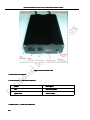
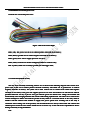
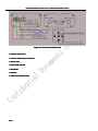
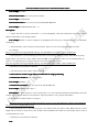
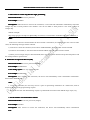
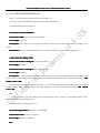
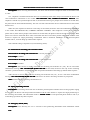
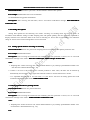
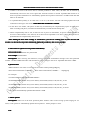
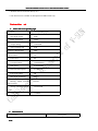
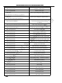
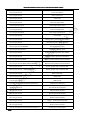
Instruction Manual V3.0 for TLT-1C GPS/GSM On-Vehicle Tracker
TLT-1C GPS/GSM Car Tracker
Instruction Manual V3.0
Shenzhen V-sun Electronics Co. Ltd.
April 1, 2012
1/40
Instruction Manual V3.0 for TLT-1C GPS/GSM On-Vehicle Tracker
Contents
Chapter One
.....................................................................................................................................
5
Preface
Preface.....................................................................................................................................
.....................................................................................................................................5
I. Overview................................................................................................................................................ 5
II. Notice....................................................................................................................................................5
.......................................................................................................................
6
Chapter Two Device Description
Description.......................................................................................................................
.......................................................................................................................6
I. Brief Introduction................................................................................................................................... 6
II. Product characteristics.......................................................................................................................... 6
III. Product use.......................................................................................................................................... 7
........................................................................................ 14
Chapter Three Initial Use and Model Description
Description........................................................................................
I. Working mode of device...................................................................................................................... 14
II. Switchover between the two modes....................................................................................................14
..............................................................................
16
Chapter Four Application and Operation in SMS Mode
Mode..............................................................................
..............................................................................16
1. Instruction to change user password....................................................................................................16
2. Instruction to request single positioning.............................................................................................. 16
3. Instruction to return Chinese address for single positioning................................................................18
4. Instruction to return Google map screenshot link for single positioning.............................................19
5. Instruction to return map link for single positioning........................................................................... 20
6. Instruction to report on time everyday.................................................................................................20
7. Set the number of returned base stations............................................................................................. 20
8. Read base station information............................................................................................................. 21
9. Instruction for calling switch............................................................................................................... 21
10. Monitoring function (mute switch of earphone)................................................................................21
2/40
Instruction Manual V3.0 for TLT-1C GPS/GSM On-Vehicle Tracker
11. Instruction for incoming call restriction switch................................................................................. 22
12. Phone positioning function................................................................................................................ 22
13. Emergency alarm (SOS).................................................................................................................... 22
14. Power off Alarm................................................................................................................................ 23
15. Fuel cutoff function........................................................................................................................... 23
16. Geo-fence function............................................................................................................................ 24
17. Overspeed alarm................................................................................................................................ 27
18. Mileage statistics function................................................................................................................. 28
19. Tow truck alert function.....................................................................................................................28
20. Low battery alarm..............................................................................................................................29
21. Instruction to switch on/off ACC status prompt................................................................................ 29
22. ACC detection and movement warning............................................................................................. 29
23. Instruction to set GPS status.............................................................................................................. 30
24. Instruction to change time zone setting............................................................................................. 31
Chapter Five Application and Operation in GPRS Mode
............................................................................ 32
Mode............................................................................
1. Change GPRS user name.....................................................................................................................32
2. Change GPRS service password..........................................................................................................32
3. Set GPRS access point (Access Point Name)...................................................................................... 32
4. Set IP address and port.........................................................................................................................32
5. Set timing data upload......................................................................................................................... 33
6. Instruction to upload current position immediately............................................................................. 34
7. Phone upload....................................................................................................................................... 34
3/40
Instruction Manual V3.0 for TLT-1C GPS/GSM On-Vehicle Tracker
8. Emergency upload............................................................................................................................... 35
9. Low voltage upload............................................................................................................................. 35
10. Historical data upload function..........................................................................................................35
11. Switch to upload invalid data.............................................................................................................36
12. Instruction to change time zone setting in GPRS mode.................................................................... 36
4/40
Instruction Manual V3.0 for TLT-1C GPS/GSM On-Vehicle Tracker
Chapter One
Preface
I. Overview
TLT-1C is a perfect combination of GSM and GPS technologies. The advanced technologies of the product in
GSM and GPS fields are verified by its accurate dimension and simple appearance. It represents a typical design
integrating the communication product and GPS positioning.
We provide professional safety-guarding and car-positioning products and solutions.
Before you use the product, please take some time and go through this instruction manual to understand
operational details and receive better services.
II. Notice
1. Please read the instruction manual carefully and operate the product properly to avoid any trouble.
2. It is recommended to install the product in a professional automobile workshop to ensure operating safety
and concealment of installation.
3. The instruction manual is only for your reference. In case of any difference between the manual and the
actual product, the latter shall prevail.
4. Product parameters and functions are subject to upgrade without notice. In case of any question, please
contact V-SUN or your distributor.
5/40
Instruction Manual V3.0 for TLT-1C GPS/GSM On-Vehicle Tracker
Chapter Two Device Description
I. Brief Introduction
TLT-1C GPS/GSM is a car remote positioning and tracking device produced based on GPS technology and
GSM/GPRS technology. It receives the latitude and longitude of the user’s location through cell phone messages
and then locates the tracker on Google Map or other digital map software; or positioning data is uploaded by the
tracker to the specified server through GPRS, and the user may search the real-time position and historical track of
the tracker on the internet.
TLT-1C GPS/GSM car tracker applies to motorcycles, electric golf carts and private cars.
II. Product characteristics
1. Built-in high-performance GPS chipset enables the product to provide accurate positioning in the event of
weak signal and to work normally in urban areas, valleys or other sight-limited districts.
2. Built-in GSM/GPRS model supports GSM900/1800MHz (850/1900 MHz), thus it can work throughout the
world.
3. It supports SMS communications or GPRS TCP connection, and receives position information through cell
phone message or used to look into movement track on the internet.
4. It provides such functions as SOS, fuel cutoff/power failure, warning by cutting off external power wire,
geo-fence, overspeed warning, historical data upload, parking throttle upload and moving car tracking timing
upload.
5. It provides voice call function (connected with earphone)
6. It is equipped with highly reliable electric circuit and complies with electronic industry standards.
III. Product use
1. Specifications
Hardware
Parameter
GSM module
MTK GSM/GPRS chipset
GSM 900/1800 double frequency , or
GSM 900/1800/850/1900 four frequency (optional)
Supports TCP protocol
6/40
Instruction Manual V3.0 for TLT-1C GPS/GSM On-Vehicle Tracker
7/40
GPS chip
GPS chip set with high sensitivity
GPS sensitivity
-160dBm
GPS frequency
L1,1575.42MHz
Code
C/A Code
Channel
50-channel, omnibearing tracking
Position accuracy
<2.5m,CEP
Speed accuracy
0.1m/s
Time accuracy
1us and synchronous with GPS time
Coordinates
WGS-84
Reacquisition
0.1s on average
Hot start
1s on average
Warm start
30s on average
Cold start
32s on average
Altitude Limit
Maximum 18,000 meter (60,000 feet)
Velocity limit
Maximum 515m/s (1000 knot)
Acceleration Speed limit
Less than 4g
Working temperature
-25℃to 70℃
Humidity
5%~95% non-concretion
Dimension
94mm×53mm×26mm
Voltage
12-24V
Instruction Manual V3.0 for TLT-1C GPS/GSM On-Vehicle Tracker
2. Product appearance
1. Product general view
Figure 1 Product Front View
8/40
Instruction Manual V3.0 for TLT-1C GPS/GSM On-Vehicle Tracker
Figure 2 Product Back View
3. LED status description
3.1 Green LED ---- GPS status indicator
Status
Description
Off
GPS unavailable
Quick flash
GPS available
3.2 Blue LED ---- GSM status indicator
9/40
Instruction Manual V3.0 for TLT-1C GPS/GSM On-Vehicle Tracker
Status
Description
Quick flash
No SIM card or GSM network
Flash once every 8s
GSM works normally
3.3 Red LED ---- charge indicator
Status
Description
Normal light
Under charging
Weak light
Charging completed
4. Product installation
4.1 SIM card installation
a. Select SIM card
● You can use SIM card provided by local mobile operators
operators..
● It supports SMS/GPRS function and has enough balance.
” in the round hole on SIM
b. Use tweezers or other tools to press the yellow "SIM card pop-up button
button”
card side
side,, then SIM card slot will pop up automatically. Load SIM card into the slot and put the slot back
into the socket until it is totally embedded and locked.
Note: 1. Attention should be given to SIM card installation sequence: firstly insert SIM card and then
connect external power supply. Never reverse the sequence to avoid damage to SIM card.
2. As SIM card slot is a power supply switch, if it is not in use for a long time, please take it out to
avoid running down of battery.
10
10//40
Instruction Manual V3.0 for TLT-1C GPS/GSM On-Vehicle Tracker
4.2 Installation of external power wire
General view of external power wire.
Figure 3 Pin
Pinss from Left to Right
PIN1 (red): 12V power wire of car to connect positive electrode of car battery;
PIN2 (black): ground wire to connect negative electrode of car battery;
PIN3 (green): ACC wire to supply power for car ACC;
PIN4 (white): control wire of fuel cutoff/power failure to connect relay;
PIN 5 (yellow): SOS wire to connect ground wire and trigger SOS;
4.3 Connection method of relay
The five wires externally connecting TLT-1C are as shown in the following diagram. The red one is 12
power wire of the car to connect positive electrode of battery. The black one is ground wire to connect
negative electrode of battery. The yellow one is SOS control wire to connect SOS switch and negative
electrode of car battery. The green one supplies power for car ACC and connects car CD and car radio in
parallel. When the car key is put on ACC gear and the green wire detects 12V voltage, the terminal will
automatically start charging function and switch GPRS timing upload mode. The white one is control wire
of fuel cutoff/power failure and connects pin 86 of relay which is a coil end. Pin 85 of the relay which is
another coil end connects fuel channel to supply 12V power (please note working volt of the relay is
consistent with working volt of the product). Pin 30 and Pin 87a are always closed ends and connect fuel
channel power circuit in series. Please install wire in a correct way. V-sun will not be responsible for device
damage caused by wrong installation.
11
11//40
Instruction Manual V3.0 for TLT-1C GPS/GSM On-Vehicle Tracker
Figure 4 Connection method of relay
5. Product accessories
1. TLT-1C GPS/GSM Car Tracker
2. Power wire
3. GPS/GSM antenna
4. Earphone
5. Battery
6. Instruction manual (CD)
12
12//40
Instruction Manual V3.0 for TLT-1C GPS/GSM On-Vehicle Tracker
Chapter Three Initial Use and Model Description
After reading brief introduction to the product, you must know how to install the product. Then it comes to
product’s use.
Firstly, as the user of such product, you need to pre-store telephone number before performing
instruction operation on the device. Telephone number is pre-stored as follows:
Instruction format: *new number 4-20 digits*user password 4 digits*serial number (1-3)**
For example: *13900000000*0000*1**
Description: If TLT-1C receives the instruction and returns confirmation message “SET USER NUMBER
(1-3) OK”, then pre-stored number will be set successfully.
Note:
1. Initial password for the device is 0000.
2. The device can pre-store 3 telephone numbers at most.
3. The instruction also applies to new number which covers existing number. For example, A is the first
pre-stored number. If B also sends instruction to set the first pre-stored number, number of B will substitute number
of A and become the first pre-stored number.
4. Any number not prestored can not be used to dial or connect device end telephone but can send
message instruction.
I. Working mode of device
The product has the following two working modes: SMS mode (message point to point) and GPRS online
mode.
1. If the user only wants to inquire for car position (longitude and latitude) with cell phone, corresponding
address on Google map or control fuel cutoff/power failure with cell phone, please select SMS mode.
2. If the user wants to monitor car real-time status and inquire for its historical track, please select GPRS
real-time online mode.
II. Switchover between the two modes
The following instruction may be used to switch over between the two modes.
Message (SMS) point-to-point mode:
Instruction format: 700+user password (4 digits)
For example: 7000000
Description: When TLT-1C receives the instruction, it will automatically switch to SMS mode. If success, it
13
13//40
Instruction Manual V3.0 for TLT-1C GPS/GSM On-Vehicle Tracker
SET MODE OK, CURRENT MODE: SMS P2P
will return confirmation message “SET
P2P”.
GPRS online working mode:
Instruction format: 710+user password (4 digits)
For example: 7100000
Description: When TLT-1C receives the instruction, it will automatically switch to GPRS mode. After
success, it will return confirmation message “SET MODE OK, CURRENT MODE: GPRS”.
14
14//40
Instruction Manual V3.0 for TLT-1C GPS/GSM On-Vehicle Tracker
Chapter Four Application and Operation in SMS Mode
Most instructions are operable under both SMS mode and GPRS mode unless otherwise specified.
1. Instruction to change user password
Instruction format: 777+new password (4 digits) + old password (4 digits)
For example: 77712340000
Description: The terminal receives the instruction and return confirmation message after success. The
message is “SET USER PASSWORD OK”.
2. Instruction to request single positioning
Instruction format: 666+user password (4 digits)
For example: 6660000
Description: When TLT-1C receives the instruction, it will return current positioning message after success.
Data message format is as follows:
Lat: latitude direction (+/-) latitude value (accurate to 5 digits after decimal point)
Long: longitude direction (+/-) longitude value (accurate to 5 digits after decimal point)
Speed: Speed KM/H (accurate to 2 digits after decimal point)
Direction: course direction (accurate to 2 digits after decimal point)
Date: YYYY-MM-DD
Time: HH:MM:SS (Greenwich Mean Time)
BS: Base station information
FIX: positioning status (A/V) (A stands for Available, V stands for Unavailable)
ID: IMEI (device IMEI number)
STATE: message status
Example of valid data message:
Lat: +22.50500
Long: +114.01000
Speed: 0.00KM/H
Direction: 315.00
Date: 2008-04-25
15
15//40
Instruction Manual V3.0 for TLT-1C GPS/GSM On-Vehicle Tracker
Time: 16:39:45
BS: 25ee0dff
Fix: A
ID: 353686009002030
STATE: SMS
Note: 1. In case of cold start and GPS is not positioned, invalid message will be returned: GPS
UNAVAILABLE, PLEASE TRY AGAIN LATER.
2. Inquire for position corresponding to latitude and longitude on Google map.
Search for obtained latitude and longitude on http://maps.google.com to view detailed position corresponding
to latitude and longitude.
For example, when sending instruction “666+password” to terminal, the following message will be obtained.
Lat:
+22.50500
Long: +114.01000
Speed: 0.00KM/H
Direction: 315.00
Date: 2008-04-25
Time: 16:39:45
BS: 25ee0dff
Fix: A
ID: 353686009002030
STATE:SMS
Then, search for +22.50500 +114.01000 on http://maps.google.com to view detailed position (as shown in the
following graph).
16
16//40
Instruction Manual V3.0 for TLT-1C GPS/GSM On-Vehicle Tracker
Figure 4
You can also input position data into local map software on PDA or navigation device to view the position (as
shown in the following graph)
Figure 5
3. Instruction to return Chinese address for single positioning
Instruction format 1: 667+user password
17
17//40
Instruction Manual V3.0 for TLT-1C GPS/GSM On-Vehicle Tracker
For example: 6670000
Instruction format 2: 667+user password+MAP
For example: 6670000MAP
Instruction format 3: 667+user password+MAP,WWW,HHH,ZZ
For example: 6670000MAP,640,480,15
Description:
1. When the device receives instruction 1, it will immediately read GPS information and return Chinese
address information to the sending number.
For example: Within 31 meters southwest of Shangjuhaoyuan east gate on Jingtian East Road in Shenzhen,
Guangdong.
2. Send instruction 2 and a website will be returned. Open it to view current position and screenshot:
For example:
http://www.gps068.com/cngps/mapaddr.asp?lng=114.09998&lat=22.55709&z=15&w=240&h=320
3. Send instruction 3 to user-defining size and zoom of screen shot. WWW is picture width, HHH is picture
height and ZZ is zoom level. (Note: WWW value and HHH value are less than 1000. It is recommended that ZZ
value is 1-20. Adjusting ZZ is to adjust zoom level of screenshot). For example,
http://www.gps068.com/cngps/mapaddr.asp?lng=114.09998&lat=22.55709&z=15&w=240&h=320
4. Default size of screenshot is 240*320.
5. The instruction is only valid in China mainland.
4. Instruction to return Google map screenshot link for single positioning
4.1 Instruction format 1: 668+user password
For example: 6680000
4.2 Instruction format 2: 668+user password, WWW, HHH, ZZ
For example: 6680000, 999, 999, 15
Description: 1. After the device receives instruction 4.1, it will read GPS information immediately and return
Google map screenshot address of local position. Open the website to view position information.
Example of screenshot website is as follows:
http://maps.google.com/maps/api/staticmap?center=22.557118,114.100010&zoom=15&size=240x320&mark
ers=22.557118,114.100010&sensor=true
2. Send instruction 4.2 to user-defining picture size. WWW stands for picture width, HHH stands for picture
height and ZZ stands for zoom level (Note: WWW value and HHH value shall not exceed 1000 and ZZ value is
recommended to be 1-20).
3. Default size of screenshot is 240*320.
18
18//40
Instruction Manual V3.0 for TLT-1C GPS/GSM On-Vehicle Tracker
5. Instruction to return map link for single positioning
Instruction format: 669+user password
For example: 6690000
Description: When the device receives the instruction, it will read GPS information immediately and return
Google map link of local position to the number. User can use PDA or smart phone to view local position on
Google map.
Website example:
http://maps.google.com/maps?f=q&hl=en&q=22.554765,114.104716&ie=UTF8&z=16&iwloc=addr&om=1
Note:
If the server cannot be connected after the above stated 3 instructions (667/668/669) are sent or due to other
cause, the following messages will be returned.
1) If the server cannot be connected, it will return: SERVER BUSY, PLEASE TRY AGAIN LATER.
2) If GPS is not available, it will return GPS UNAVAILABLE, PLEASE TRY AGAIN LATER.
3) When you use Google map in China mainland, there may be deviation between the positioned position and
the actual position in special cases.
6. Instruction to report on time everyday
Instruction format: 665+user password+HHMM
For example: 66500001022
Close timing report: 665+user password+OFF
For example: 6650000OFF
Description: After receiving the instruction, the device will immediately return confirmation information:
SET DAILY REPORT OK.
Note:
1. Using this instruction, the user may receive a piece of positioning information at a stated time, with its
format as shown in “Single positioning request”.
2. HH stands for hour with defined range of [00, 23]. MM stands for minute with defined range of [00, 59].
7. Set the number of returned base stations
Instruction format: 55X+user password (4 digits)
For example: 5510000
Description: After success to receive the instruction, the device will immediately return confirmation
19
19//40
Instruction Manual V3.0 for TLT-1C GPS/GSM On-Vehicle Tracker
information:
SET BASESTATION OK.
Note: 1. X is base station number with value range of [0, 6].
2. If X is 0, position information contains no base station information.
3. Default number of base station is 1.
8. Read base station information
Instruction format: 111+user password (4 digits)
For example: 1111234
Description: After success to receive the instruction, the device will return the following message to the
sender.
Data format: BS: base station information 1, base station information 2, base station information …n
9. Instruction for calling switch
Instruction format of calling off: 150+user password
For example: 1500000
Instruction format of calling on: 150+user password
For example: 1510000
Description: 1. After receiving instruction of calling off, TLT-1C will turn off calling function (including SOS,
SET
power cutoff warning calling, fence warning calling, overspeed warning) and return confirmation message “SET
VOICE CALL: OFF
OFF”.
2. After receiving instruction of calling on, TLT-1C will turn on calling function (including SOS, power cutoff
SET VOICE
warning calling, fence warning calling, overspeed warning) and return confirmation message “SET
CALL: ON
ON”.
Note:
1. In case of calling off, when SOS, power cutoff warning, fence warning or overspeed warning occurs,
message will be returned instead of call.
2. Default setting is calling function on.
10. Monitoring function (mute switch of earphone))
Instruction format: 00X+user password
For example: 001000 or 0000000
20
20//40
Instruction Manual V3.0 for TLT-1C GPS/GSM On-Vehicle Tracker
Description: When receiving the instruction, the device will set status of earphone switch in accordance with
X value.
X=1, earphone is switched off and the device is in monitoring mode. After setup is successful, the device will
send confirmation information to the sender: SET PROFILE OK, CURRENT PROFILE: SILENT. After
earphone is turned off, if prestored phone calls in, the terminal will not give prompt sound. About 10 seconds later,
the phone will be answered automatically. The user can hear sound from the device side but the device side cannot
hear the user.
When X=0, the earphone is turned on. After setup is successful, the device will send confirmation information
to the sender: SET PROFILE OK, CURRENT PROFILE: NORMAL. After earphone is turned on, if prestored
phone calls in, there will be prompt sound. About 10 seconds later, the phone will be answered automatically. Both
parties can converse with each other. After conversation the device will return position information with the same
format as "request for single positioning”. Information status is STATUS: ANSWER. If non-prestored phone
number calls in, it will be hung up without other response.
Note: Default setting is earphone on (non-monitoring status).
11. Instruction for incoming call restriction switch
Instruction for incoming call restriction on
on:: 170+user password
For example: 1700000
Instruction for incoming call restriction off: 171+user password
For example: 1710000
Description: After success to receive instruction for incoming call restriction on (170), TLT-1C will return
confirmation message: SET UNLIMITED MODE OFF OK. At this time, the device can only receive incoming
call from 3 prestored numbers. Incoming call from non-prestored number will be hung up without other response.
After success to receive instruction for incoming call restriction off (171), TLT-1C will return confirmation
message: SET UNLIMITED MODE ON OK. The device can answer incoming call from any cell phone.
Note: Default setting is incoming call restriction on.
12. Phone positioning function
Description: If incoming call is from one of the three prestored phone numbers and it is hung up after ringing
for 2-5 times, the device will send position information with the same format as “request for single positioning” to
the incoming call number. The information status is STATE: CALL
CALL. If non-prestored phone number calls in, it
will be hung up without any other response.
13. Emergency alarm (SOS)
Description: Press SOS key for over 3 seconds to send positioning information with information format
21
21//40
Instruction Manual V3.0 for TLT-1C GPS/GSM On-Vehicle Tracker
returned from “request for single positioning” to the three prestored phone numbers. Information status is STATE:
SOS. At the same time, the first prestored phone number will be called. If it fails (the phone is turned off or cannot
be connected), the second and the third phone number will be called in sequence.
Note: If calling status is off, message will be sent to prestored user instead of calling him.
14. Power off Alarm
Instruction to turn on power cutoff warning: 011+user password
For example: 0110000
Instruction to turn off power cutoff warning: 010+user password
For example: 0100000
Description: After receiving instruction 011, the device will return confirmation information: DEFENCE ON
and enter defence status. Once external power supply is cut off unexpectedly, the device will send positioning
information of “request for single positioning” to the three prestored numbers. Information status is STATE: DEF.
At the same time, the first prestored phone number will be called. If it fails (the phone is turned off or cannot be
connected), the second and the third phone number will be called in sequence.
After receiving instruction 010, the device will return confirmation information: DEFENCE OFF
OFF. Then
power cutoff warning function is cancelled and the device will stop monitoring unexpected cutoff of external
power supply.
Note:
1. Default power cutoff warning is off.
2. If calling status is off, message will be sent to prestored user instead of calling him.
15. Fuel cutoff function
15.1. Fuel cutoff and power failure
15.1.1 Fuel cutoff/power failure message instruction: 900+user password
15.1.2 Fuel cutoff/power failure message confirmation instruction: 901+user password
Description: As fuel cutoff/power failure operation is dangerous to some extent, one more confirmation
operation is necessary.
After receiving instruction 900, TLT-1C will return confirmation message “Confirm Power OFF?” and wait
for instruction 901. If it receives confirmation instruction (901) sent by the user within 10 minutes, TLT-1C fuel
channel power supply will be cut off. After completion, it will return confirmation message “POWER OFF OK”.
15.1.3 Fuel cutoff/power failure single instruction format: 940+user password
Description: 940=900+901. After receiving instruction from prestored number, TLT-1C will immediately
perform fuel cutoff/power failure.
22
22//40
Instruction Manual V3.0 for TLT-1C GPS/GSM On-Vehicle Tracker
2. Recovery of fuel cutoff/power failure
15.
15.2.
(resume the oil and power)
15.2.1 Fuel cutoff/power failure recovery instruction: 902+user password
15.2.2 Fuel cutoff/power failure recovery confirmation instruction: 903+user password
Description: After success to receive the instruction 902, TLT-1C will send confirmation information
“Confirm Power ON?” and wait for instruction 903. If it receives confirmation instruction (903) sent by the user
within 10 minutes, TLT-1C fuel channel power supply will be recovered. After completion, it will send
confirmation information to the sender “POWER ON OK”.
15.2.3 Fuel cutoff/power failure recovery single instruction format: 941+user password
Description: 941=902+903. After receiving instruction from prestored number, TLT-1C will immediately
perform fuel cutoff/power failure recovery.
Note: 1. If fuel cutoff/power failure instruction has been set, the status will remain when the product is
rebooted.
2. The function is accompanied by some risk. For example, if the instruction is sent when the car
travels fast on the highway, traffic accident might be caused. Therefore, please do not use the function unless
necessary.
16. Geo-fence function
Geo-fence of the device has the following two modes: round Geo-fence and square geo-fence.
Round Geo-fence takes the set coordinates as center of circle and uses the set semi-diameter to determine
fence scope. Square Geo-fence uses 4 known latitude and longitude points to determine a square fence.
When the function is activated, once TLT-1C steps beyond fence scope, it will send positioning information
with the information format returned by above stated “request for single positioning” to the three prestored
numbers. Information status is STATE: OS. At the same time, the first prestored phone number will be called. If it
fails (the phone is turned off or cannot be connected), the second and the third phone number will be called in
sequence.
When TLT-1C enters fence scope again, it will send positioning information with information format returned
from “request for single positioning” to the three prestored number immediately. Information status is STATE: RS.
At the same time, the first prestored phone number will be called. If it fails (the phone is turned off or cannot be
connected), the second and the third phone number will be called in sequence.
16.1 Setting of round Geo-fence scope
The user may at his discretion select the following formats to operate according to the input different formats
of coordinates.
nstruction format 1: 003 + user pass word E/Wdddmm.mmmmN/Sddmm.mmRzzz.z
Instruction
23
23//40
Instruction Manual V3.0 for TLT-1C GPS/GSM On-Vehicle Tracker
For example: 0030000E11406.0024N2233.4230R0.1
When receiving the instruction, TLT-1C will return confirmation message to the sender: SET GEO-FENCE
OK and turn on Geo-fence function.
Description: E: east longitude; W: west longitude; N: north latitude; S: south latitude. south latitude. Here E
and N are used to explain as an example. Please select corresponding coordinate formats in accordance with actual
geographic position. Each section’s meaning of the example is as follows:
Edddmm.mmmm is longitude information with degree and minute as unit, among which ddd stands for degree
and mm.mmmm stands for minute (4 digits after decimal point is maintained and zero cannot be omitted).
Nddmm.mmmm is latitude information with degree and minute as unit, among which dd stands for degree and
mm.mmmm stands for minute (4 digits after decimal point is maintained and zero cannot be omitted).
zzz.z is radius with definition domain of [0.1, 999.9] and unit of KM.
Instruction format 2: 004 + user password E/Wddd.dddddN/Sdd.ddddRzzz.z
For example: 0040000E114.10004N22.55705R999.9
When receiving the instruction, TLT-1C will return confirmation message to the sender: SET GEO-FENCE
OK and turn on Geo-fence function.
Description: E: east longitude; W: west longitude; N: north latitude; S: south latitude. Here E and N are used
to explain as an example. Please select corresponding coordinate formats in accordance with actual geographic
position. Each section’s meaning of the example is as follows:
Eddd.ddddd is longitude information with degree as unit, among which ddd.ddddd stands for degree (5 digits
after decimal point is maintained and zero cannot be omitted).
Ndd.ddddd is latitude information with degree as unit, among which dd.ddddd stands for degree (5 digits after
decimal point is maintained and zero cannot be omitted).
zzz.z is radius with definition domain of [0.1, 999.9] and unit of KM.
Instruction format 3: 005 + user password Rzzz.z
For example: 0050000R0.1
Description: After receiving the instruction, TLT-1C will extract current longitude and latitude information as
fence coordinate from the latest GPS data and takes R value as radius. It also turns on Geo-fence and send
confirmation message to the sender after success: GE0-FENCE ON.
Note:
zzz.z is radius with definition domain of [0.1, 999.9].
16.1.1 Instruction to turn on round geo-fence
Turn on geo-fence: 211 + user password
24
24//40
Instruction Manual V3.0 for TLT-1C GPS/GSM On-Vehicle Tracker
After receiving the instruction, TLT-1C will return confirmation message: GEO-FENCE ON.
16.1.2 Turn off round Geo-fence instru
instruction:
Turn off geo-fence: 210 + user password
After receiving the instruction, TLT-1C will return confirmation message: GEO-FENCE OFF.
Note: 1. Fence radius shall not exceed its defined domain. When decimal digit is 0, please add 0. For example,
when R is 1, please enter 1.0.
2. If calling status is off, message will be sent to prestored user instead of calling him.
3. Degree and minutes is of sexagesimal system, i.e., 1d=60m.
16.2 Setting of square Geo-fence scope
Instruction format: 006 + user password + GX, IO/I/O, E/W longitude upper limit + N/S latitude upper limit,
E/W longitude lower limit + N/S latitude lower limit.
For example: 0060000G1,IO,E114.10004N22.55705,E115.10006N23.55706
After receiving the instruction, TLT-1C will return confirmation message: SET SQUARE GEO-FENCE
GX(IO/I/O) OK.
Description: GX is Geo-fence X, whose value range is [1, 16]]. IO means warning for both outgoing and
incoming fence; I means warning for incoming fence; O means outgoing fence. Longitude and latitude value take
degree as unit. 5 digits after decimal point shall be reserved and 0 shall not be omitted.
IO means warning for both outgoing and incoming fence; I means warning for incoming fence; O means
outgoing fence.
Note:
(1) After setting is completed, fence is turned on automatically. Now, default fence type is IO, i.e., warning
for both outgoing and incoming fence.
(2) If calling status is off, message will be sent to prestored user in SMS mode instead of calling him.
(3) Value set by the instruction is not subject to power off or switch on/off until change instruction or
restoration operation is received again.
(4) After restoration, longitude value is indicated by 0. Fence is in cutoff status.
16.2.1 Turn on square geo-fence
Instruction format to turn on all square geo-fence: 311 + user password
For example: 3110000
Instruction format to turn on single square geo-fence: 311 + user password +GX
25
25//40
Instruction Manual V3.0 for TLT-1C GPS/GSM On-Vehicle Tracker
For example: 3110000G5
Description: The instruction is used to turn on all square Geo-fence and turn on single square geo-fence. GX
stands for Geo-fence X, whose value range is【1,16】. After receiving the instruction, TLT-1C returns confirmation
message: SET ALL SQUARE GEO FENCE: ON. When turning on single square geo-fence, it returns
confirmation message: SET SQUARE GEO FENCE GX: ON.
16.2.2 Instruction to turn off square geo-fence
Instruction format to turn off all rectangular geo-fence: 310 + user password
For example: 3100000
Instruction format to turn off single rectangular geo-fence: 310 + user password +GX
For example: 3100000G5
Description: The instruction is used to turn on all rectangular Geo-fence and turn on single rectangular
geo-fence. GX stands for Geo-fence X, whose value range is [1, 16]. After receiving the instruction, TLT-1C
returns confirmation message: SET ALL SQUARE GEO FENCE: OFF. When turning on single square
geo-fence, it returns confirmation message: SET SQUARE GEO FENCE GX: OFF.
Note: If multiple set square fences give warning at the same time. G1 will call and G2, G3, G4… will send
position message instead of calling. As for the ex-factory configuration or in case of restoration, the status is RS by
default.
Notice:
Above stated geo-fences are optional. When the device receives Geo-fence setting instruction, Geo-fence
function will be activated automatically. When Geo-fence function is activated again after turned off,
previous setting remains valid.
17. Overspeed alarm
Instruction format: #122#user password#X##
For example: #122#0000#250##
After receiving the instruction, TLT-1C will return confirmation message: SET RATE LIMIT:250.
Description:
1. X is speed benchmark value, which is an integral number. Its unit is KM/H with defined domain of [0, 999].
When X=0, overspeed warning function is turned off.
2. After the function is activated, if travel speed exceeds set speed, the device will send position information
with information format returned from “request for single positioning" to the three prestored numbers immediately.
Information status is STATE: OVERSPEED. It will also call the first prestored number immediately. If it fails
(the phone is turned off or cannot be connected), the second and the third phone number will be called in sequence.
Then, if travel speed is less than set speed, the device will send position information with information format
26
26//40
Instruction Manual V3.0 for TLT-1C GPS/GSM On-Vehicle Tracker
returned from “request for single positioning" to the three prestored numbers immediately. Information status is
STATE: SAFE SPEED. It will also call the first prestored number immediately. If it fails (the phone is turned off or
cannot be connected), the second and the third phone number will be called in sequence.
18. Mileage statistics function
18.1 Instruction to turn off mileage statistics
Instruction format: 140+user password
For example: 1400000
Description: After receiving the instruction, TLT-1C will return confirmation message: SET MILEAGE
STATISTICS OFF OK. Mileage statistics function will remain in turnoff status.
18.2 Instruction to turn on mileage statistics
The instruction can be used to set the interval of timing report on total mileage.
Instruction format: 141+PW
Description: After receiving the instruction, TLT-1C will return confirmation message: SET MILEAGE
STATISTICS ON OK. Mileage statistics function will be turn on.
18.3 Instruction to set initial mileage value (zero clearing)
Instruction format: 142+PW
Description: After receiving the instruction, TLT-1C will return confirmation message: MILEAGE
STATISTICS RESET OK.
18.4 Instruction to read current mileage
Instruction format: 143 + user password.
For example: 1430000
Description: After receiving the instruction and confirming that user password is correct, the device will read
current total mileage value and return the following message to the number which sends the instruction: MILEAGE
STATISTICS:ON,CURRENT TOTAL MILEAGE:XX (XX means current mileage value with unit of M).
Note:
1. If zero clearing is not performed, the mileage read is accumulated value;
2. Mileage statistics is off by default.
19
19.. Tow truck alert function
27
27//40
Instruction Manual V3.0 for TLT-1C GPS/GSM On-Vehicle Tracker
19.1 Turn on tow truck alert: 181 + user password
For example: 1810000
.2 Turn off tow truck alert: 180 + user password
19
19.2
For example: 1800000
Description: After receiving the instruction, TLT-1C will return confirmation message: TOWED ALERT
ON. Now, tow truck alert function has been activated. When ACC is turned off, if it is detected that the device
continuously vibrates for 20 seconds, the device will call the first prestored phone number. If it fails (the phone is
turned off or cannot be connected), the second and the third phone number will be called in sequence. Finally, the
device will send positioning information returned from “request for single positioning” to the prestored numbers.
Information status is STATE: TOWED.
Note: 1. Default setting is tow truck alert on with vibration time of 20 seconds.
2. If the function is not needed, the user can send instruction 180 to turn off the function. If the function
is not turned off, car vibration will trigger alert after parking.
20. Low battery alarm
In case of too low working voltage (electricity quantity), TLT-1C will send position information with
information format of returned “request for single positioning” to the prestored three numbers. Information status
will be updated to STATE: LP
LP. The information will be sent for 3 times with an interval of 1 minute.
21. Instruction to switch on/off ACC status prompt
1>Instruction to switch on ACC status prompt: 091 + user password
For example: 0910000
2>Instruction to switch off ACC status prompt: 090 + user password
For example: 0900000
Description: After receiving instruction 091 and confirming that user password is correct, TLT-1C will send
confirmation message to the sender “ACC STATE PROMPT: ON”. When ACC is being switched on/off, the device
will send current position information to all prestored numbers immediately: “AUTO START/AUTO STOP”.
After receiving instruction 090 and confirming that user password is correct, TLT-1C will send confirmation
message to the sender “ACC STATE PROMPT: OFF”. When ACC is being switched on/off, TLT-1C will not send
any data information.
Note: Default setting is ON. This setting isn’t influenced by the device switch-off/on until change instruction
or restoration operation is performed again.
22. ACC detection and movement warning
28
28//40
Instruction Manual V3.0 for TLT-1C GPS/GSM On-Vehicle Tracker
22.1 Instruction to set movement warning area: 008 + user password + Rzzz.z
For example: 0080000R100.0
22.2 Instruction to turn off movement warning: 009 + user password
For example: 0090000
After receiving instruction 008, TLT-1C will return confirmation message: SET MOVE RADIUS OK
OK. After
receiving instruction 009, TLT-1C will return confirmation message: MOVE DEFENCE: OFF
OFF.
Description: 1. zzz.z is mobile warning area radius, whose defined domain is [0.1, 999.9] with unit of KM.
2. After mobile warning area is set successfully, if TLT-1C detects that ACC status is switched from on to off,
the device will read current position information as origin of coordinates 3 minutes later. Whether GPS data is valid,
the device will perform electronic area defence with zzz.z as radius.
While ACC is turned off, if TLT-1C detects that the defence area is stepped beyond, it will send movement
warning message to all prestored numbers in message mode. Information status is STATE: ACC OS (or upload
current position information to the server in GPRS mode) and dial prestored number. (Whether to call is controlled
by 150/151. After restoration, message is sent instead of calling).
When it enters defence area again after stepping beyond defence area, the device will also send message and
call prestored phone (or upload position message in GPRS mode). Information status is ACC RS.
When TLT-1C detects that ACC status is switched from off to on, movement warning function will be
automatically cancelled. When ACC status is switched from on to off, movement warning function will be
activated again.
23. Instruction to set GPS status
Message instruction may make GPS in three statuses: on/off/self adapting. GPS is switched on when delivered
from the factory or reset.
23.1 Instruction to turn on GPS
Instruction format: 222 + user password (4 digits)
For example: 2220000
Description: After receiving the instruction, TLT-1C will return confirmation message: GPS ON OK.
23.2 Instruction to turn off GPS
Instruction format: 333 + user password (4 digits)
For example: 3330000
Description: After receiving the instruction, TLT-1C will return confirmation message: GPS OFF OK.
23.3 Instruction for self adapting GPS
Instruction format: 100 + user password
29
29//40
Instruction Manual V3.0 for TLT-1C GPS/GSM On-Vehicle Tracker
For example: 1000000
Description: After receiving the instruction, TLT-1C will return confirmation message: VIBRATION
SENSOR ON OK.
Note:
1. If built-in vibration sensor detects device vibration, it will turn on GPS. If it does not detect vibration within
5 minutes, GPS will be turned off automatically.
2. If the car travels on the highway or the flat road for a long time, GPS may remain in sleep status rather than
awake for a long time. If the user want to position and track the real-time position at that time, please send
“222 + user password” to restart GPS.
24. Instruction to change time zone setting
Instruction format: 896 + user password 4 digits + D + NN
For example: 8960000E08
Description: After receiving the instruction, TLT-1C will return confirmation message: TIME ZONE SET
OK,CURRENT
E8.
OK,CURRENT:E8.
1. D takes E or W to indicate east or west time zone respectively. N takes a 2-digit number (1-12) to indicate
time zone number.
2. After success to set 896000E08, all time-related data will be GPS time plus 8. After success to set
896000W07, all time-related data will be GPS time minus 7.
3. Default value is Greenwich time (UTC).
Note: When the instruction is set, data upload time in GPRS mode will not change. If the user wants to
change data upload time, please refer to instruction 897 in GPRS mode in the next chapter.
30
30//40
Instruction Manual V3.0 for TLT-1C GPS/GSM On-Vehicle Tracker
Chapter Five Application and Operation in GPRS Mode
Send “710 + user password” to switch to GPRS mode. In the mode, TLT-1C can also prestore three phone
numbers (No.1, No.2 and No.3), a set of TCP/IP server IP address and port number, 4-digit GPRS password and an
APN number at GPRS access point. Instructions in SMS mode can also be used in GPRS mode.
1. Change GPRS user name
Instruction format: #801#user password# new user name##
For example: #801#0000# username##
Description: After receiving the instruction, TLT-1C will return confirmation message: CHANGE
USERNAME OK.
2. Change GPRS service password
Instruction format: #802#user password# new service password# old service password##
For example: #802#0000#1111#0000##
Description: After receiving the instruction, TLT-1C will return confirmation message: CHANGE
PASSWORD OK.
3. Set GPRS access point (Access Point Name)
Instruction format 1: #803#user password#APN##
For example: #803#0000#CMNET##
Instruction format 2: #803#user password #APN#APN user name# APN password##
Description: After receiving the instruction, TLT-1C will return confirmation message: SET GPRS APN
OK.
Note:
1. As different GSM/GPRS service providers provide different APN, please select instruction format 1 or 2 in
accordance with the APN provided by your local service provider.
2. APN is CMNET at the factory or after reset. APN is constituted by 3~35 characters which may be alpha,
number, dot (.), underscore (_) or hyphen (-). APN user name and APN password are respectively
constituted by 3~30 characters which may be numbers or alphas.
4. Set IP address and port
31
31//40
Instruction Manual V3.0 for TLT-1C GPS/GSM On-Vehicle Tracker
Instruction format: #804#user password # fixed IP address/ domain name #port##
For example: #804#0000#210.83.225.181#6998##,
Or #804#0000#www.gps068.com#6998##
Description: After receiving the instruction, TLT-1C will return confirmation message: SET SERVER IP
AND PORT OK.
5. Set timing data upload
Timing data upload has the following two modes: traveling car tracking mode and turn-off mode. In
accordance with different settings of GPS sampling time and upload quantity, data are intensively uploaded to
display real-time trace with more detail in the event of traveling car. Fewer data are uploaded to save SIM flow
charge as well as ensure some tracking effects in case of turnoff.
5.1 Timing upload mode for traveling car tracking
Instruction format: #805# user password# sampling interval T# uploaded data quantity each time N##
For example: #805#0000#10#6##
Description: After receiving the instruction and confirming that user password is correct, TLT-1C will send
SET GPS SAMPLING TIME AND QUANTITY OK
confirmation message to the sender “SET
OK”.
Note:
1. Sampling time T takes second as unit, whose defined domain is [10, 59999]. Uploaded data number N for
each time has a defined domain of [1, 50].
2. If data is not sent to the server due to network problem or other cause, the data will be backed up
automatically and sent to the server again after network resumes to normal. data status is AUTO.
. 3. If “uploaded data quantity N for each time” is 0, the device will turn off timing upload and send
confirmation message to the sender: GPRS TIMER STOP
STOP.
5.
5.22 Timing upload mode for parking throttle
Instruction format: #809# user password#X#Y##
For example: #809#0000#10#6##
Description: After receiving the instruction and confirming that user password is correct, TLT-1C will send
GPRS REPORT SAMPLING 2 OK
confirmation message to the sender “GPRS
OK”.
Note:
1. Sampling time X takes second as unit, whose defined domain is [10, 59999]. Uploaded data number Y for
each time has a defined domain of [1, 50].
32
32//40
Instruction Manual V3.0 for TLT-1C GPS/GSM On-Vehicle Tracker
2. If data is not sent to the server due to network problem or other cause, the data will be backed up
automatically and sent to the server again after network resumes to normal. Uploaded data format is as
shown in position information of “immediately upload current position instruction” in GPRS mode and data
status is AUTOLOW.
3. If “uploaded data quantity Y for each time” is set as 0, the device will turn off timing upload and send
confirmation message to the sender: GPRS REPORT SAMPLING 2 STOP
STOP.
4. In the above two modes, 300 pieces of data may be backed up for complementary report for blind area.
After exceeding 300 pieces, new data will automatically override former backup data.
5. When complementary data is sent, if there are lots of pieces of stored data, 50 pieces will be uploaded at
one time. If data number is less than 50, all of them will be uploaded at one time. Current data will not be
uploaded until all complementary data are sent.
After making the three basic settings as stated above, you can see running trace of your own car and
monitor car movement on product monitoring platform provided by the service provider.
6. Instruction to upload current position immediately
Instruction format: #806# user password##
For example: #806#0000##
Description: After receiving the instruction, TLT-1C will send confirmation message to the first prestored
number: “START GPRS UPLOAD” and send data in current storage to the server. Uploaded data status is SMS.
Upload format:
#IMEI number # user name # service password # status # data quantity[CR][LF]
#base station information$GPRMC……#base station information$GPRMC……##[CR][LF]
For example:
#123456789000001#SR-6869BE#0000#SMS#3
#25ee0dff$GPRMC,083945.180,A,2233.4249,N,11406.0046,E,0.00,315.00,251207,,,A*6E
#25ee0dff$GPRMC,083950.180,A,2233.4249,N,11406.0046,E,0.00,315.00,251207,,,A*6E
#25ee0dff$GPRMC,083955.180,A,2233.4249,N,11406.0046,E,0.00,315.00,251207,,,A*6E ##
Note: Status of immediately uploaded data format is SMS.
7. Phone upload
Description: When one of the three prestored phone numbers calls in and is hung up after ringing for 2-5
times, it will operate as “immediately upload current position” . Status prompt is CALL.
33
33//40
Instruction Manual V3.0 for TLT-1C GPS/GSM On-Vehicle Tracker
8. Emergency upload
Description: Press SOS key for more than 3 seconds, and the device will operate as “instruction to
immediately upload current position”; the status indicates SOS. At the same time, it will call the first prestored
number. If it fails (the phone is turned off or cannot be connected), the second and the third phone number will be
called in sequence.
Note: If calling status is off, it will send position message to the server instead of calling the phone.
9. Low voltage upload
If working voltage of TLT-1C is lower than the set value, the device will operate as “instruction to
immediately upload current position” and add “LP” auxiliary attribute into data status to show current status. The
information will be sent for 3 times with an interval of 1 minute.
10. Historical data upload function
In order to use the function in SMS mode, please switch to GPRS to set IP and APN.
10
10..1 Set historical data record
nstruction format: #807# user password #X##
Instruction
For example: #807#0000#30##
Description: After receiving the instruction and confirming that user password is correct, TLT-1C will set
historical record sampling frequency as X. If X=0, the device will close historical data record. If X!=0, the device
will take X seconds as interval to store received GPS data. After success, it will return confirmation message to the
sender: SET SAMPLING OK.
Note:
1. X is historical record sampling frequency, whose defined domain is [0, 999] with second as unit.
2. Size of each data is around 100B (BYTE).
3. Memory space distributed to historical data record is 864KB (BYTE) and stack override method is used to
update data storage. If X=30, data for about 3 days will be recorded. If X=300, data for about 30 days will
be recorded. When stored data reach 864KB, newly received data will override earlier data.
4. If power saving function is activated and TLT-1C remains static for a long time, historical record will be
automatically closed until TLT-1C is wakened up and GPS is turned on.
2. Instruction to set historical data upload
10.
10.2.
1>Upload 24-hour historical record:
Instruction format: #808# user password #24##
34
34//40
Instruction Manual V3.0 for TLT-1C GPS/GSM On-Vehicle Tracker
For example: #808#0000#24##
Description: After receiving the instruction, TLT-1C will return confirmation message: START UPLOAD
24H HISTORICAL RECORD. It will send historical data recorded in the past 24 hours to the server with the same
format as position information mentioned in “instruction to immediately upload current position” and information
status is SOTRAGE.
2>Read all data records:
Instruction format: #808#0000##
Description: After receiving the instruction, TLT-1C will return confirmation message: START UPLOAD
ALL HISTORICAL RECORD. It will send all historical data recorded in storage area to the server with the same
format as the position information mentioned in “instruction to immediately upload current position” and
information status is SOTRAGE.
11. Switch to upload invalid data
Instruction format: 08X + user password 4 digits
Function description: After receiving the instruction, TLT-1C will be able to determine whether to upload
invalid data in accordance with X value.
If X=0, the device will turn off the function of uploading invalid data. After success, it will return
confirmation message: INVALID DATA UPLOAD: OFF. At this time, invalid data upload will be turned off and
only valid data will be uploaded.
Note: 1. Default setting is turning off invalid data upload.
2. The function is available for GPRS mode only.
12. Instruction to change time zone setting in GPRS mode
Instruction format: 897 + user password 4 digits + D + NN
For example: 8970000E08
Description: After receiving the instruction, TLT-1C will return confirmation message: TIME ZONE SET
OK,CURRENT:DN(For example: TIME ZONE SET OK,CURRENT:E8).
Note
1. D takes E or W to indicate east or west time zone. NN takes a 2-digit number (1-12) to indicate time zone
number.
2. If successes to set 8970000E08, GPRS data upload time will be GPS time plus 8. If successes to set
8970000W07, GPRS data upload time will be GPS time minus 7.
35
35//40
Instruction Manual V3.0 for TLT-1C GPS/GSM On-Vehicle Tracker
3. Default value is Greenwich time (UTC).
4. The instruction is available for data upload in GPRS mode only.
Instruction set
1. Status and corresponding signs
Status
Corresponding signs
666 single request
SMS
Phone positioning
CALL
Accept calling
ANSWER
Active seeking help
SOS
Electricity shutoff alarm
DEF
Quit from fence
OS
Enter fence
RS
Overspeed alarm
OVERSPEED
Safe speed
SAFESPEED
Historical data upload
STORAGE
Low power alarm
LP
806 single positioning
SMS
Moving vehicle tracking
timing upload
AUTO
Timing upload for parking
throttle
AUTOLOW
Trailer alarm
TOWED
2. Instruction set
Instruction
36
36//40
Description
Instruction Manual V3.0 for TLT-1C GPS/GSM On-Vehicle Tracker
000+user password
001+user password
monitor
mode cutoff
monitor mode open
003+user
passwordE/Wxxxx.xxxxN/Syyyy.yyyyRzzz.z
Fence scope setting(unit: degree, minute)
004+user
passwordE/Waaa.aaaaaN/Sbb.bbbbbRzzz.z
Fence scope setting(unit: degree,minute)
005+user passwordRzzz.z
006+user password,Gx,I/O,E/W+N/S,E/W+N/S
008+user password+Rzzz.z
Fence scope setting(current position
coordinate)
Fence scope setting(unit: degree)
Set and start displacement alarm instruction
009+ user password
close displacement alarm
010+user password
Open electricity shutoff alarm
011+user password
Close electricity shutoff alarm
080+user password
Close invalid data upload under GPRS mode
081+user password
Open invalid data upload under GPRS mode
090+user password
Instruction for closing ACC status shift
091+user password
opening ACC status shift
100+user password
Open electricity saving function
111+user password
Single return base station information
#122#user password#X##
Overspeed alarm setting
140+user password
Closing distance statistics
141+user password
Start distance statistics
142+user password
zero clearing setting
of distance statistics
143+user password
Read distance statistics
150+user password
Close calling
151+user password
Start calling
170+user password
Start calling limit
171+user password
Close calling limit
180+user password
Close trailer alarm
181+user password
Start trailer alarm
37
37//40
Instruction Manual V3.0 for TLT-1C GPS/GSM On-Vehicle Tracker
210+user password
Close round fence
211+user password
Start round fence
222+user password
Start GPS
310+user password
Close all square fence
310+user password,Gx
311+user password
311+user password,Gx
Close single square fence
Start all square fence
Start single square fence
333+user password
Close GPS
4xx+user password
Timing return positioning information
55x+user password
Set returning base station quantity
665+user password+HHMM
665+user password+OFF
Set daily timing report
Close daily timing report
666+user password
Single positioning return user number
667+user password
Return Chinese position information
667+user password+MAP
Return Chinese address and screenshot
667+user password+MAP,WWW,HHH,ZZ
Return Chinese address and screenshot
668+user password
Return google map screenshot link
668+user password,WWW,HHH,ZZ
Return google map screenshot link
669+user password
Return map link
700+user password
SMS mode
710+user password
GPRS mode
777+new user password+old user password
Change user password
900+user password
Pre-shutoff electricity/fuel
901+user password
Shutoff electricity/fuel
902+user password
Pre-restore electricity/fuel
903+user password
Restore electricity/fuel
940+user password
941+user password
*prestored number*user password*sequence**
38
38//40
Single
shutoff electricity/fuel
Restore electricity/fuel
Change pre-stored number
Instruction Manual V3.0 for TLT-1C GPS/GSM On-Vehicle Tracker
#801#user password#new user name##
Change GPRS user name
#802#user password#new service password#old
service password##
#803#user password#APN##
Set GPRS access point
#803#user password#APN#APN user
name#APN password##
Set GPRS access point
#804#user password# fixed IP address and
port##
#805#user password#sampling
upload quantity each time##
#806#user password##
Change GPRS service password
interval
T#
Set IP address and port number
Set timing upload mode for Moving vehicle
tracking
Single request uploading current position
#807#user password#X##
Set historical rewire sampling rate
#808#user password#24##
Upload 24h historical data
#808#user password##
Upload all historical data
#809#user password#x#y##
Set timing upload mode for Parking throttle
896+user password+D+NN
Set time zone
897+user password+D+NN
Set GPRS time zone
39
39//40
Instruction Manual V3.0 for TLT-1C GPS/GSM On-Vehicle Tracker
Warranty
The following after services are provided in order to serve and satisfy the customers:
Ⅰ. Warranty scope:
1. The product may be replaced free of charge within 30 days since purchase in the event that it is ineligible
when normal operation (man-made sabotage excluded) and without dismantlement.
2. The product will be maintained and repaired by V-SUN free of charge within one year after purchase if it
meets with trouble in normal operation due to ineligible quality and without dismantlement.
3. The product shall be repaired upon payment beyond warranty period.
4. the product shall be repaired after the authorization of V-SUN.
Ⅱ. Exemption clauses
Any damage or malfunction of fittings incurred by user’s improper operation, maintenance, or storage;
2. Any damage or malfunction caused due to majeure such as rain, natural disaster, etc.
The instruction manual subjects to successive update without prior notice. Please contact our sales manager or
technicians if needed.
40
40//40