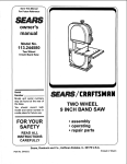
1
v
For Future Reference
r
,9__ARS
owners
manual
MODEL NO.
113.244530
VARIABLE SPEED
10-1NCH BAND SAW
Serial
Number.
Model and serial numbers
may be found on the back
of the saw.
You should record both
model and serial number in
a safe place for future use.
___AIRS / r.RRFT$ MRN_._
FOR YOUR
SAFETY:
READ ALL
INSTRUCTIONS
CAREFULLY
VARIABLESPEED
10-1NCH BAND SAW
• assembly
• operating
• repair parts
Sold by SEARS, ROEBUCK AND CO., Chicago,
Part No. SP5620
IL 60684 U.S.A.
FULL ONE YEAR WARRANTY ON CRAFTSMAN
BAND SAW
If within one year from the date of purchase, this Craftsman Band Saw fails due to a defect in
material or workmanship, Sears will repair it, free of charge.
WARRANTY SERVICE IS AVAILABLE BY SIMPLY CONTACTING THE NEAREST SEARS SERVICE CENTER/DEPARTMENT THROUGHOUT THE UNITED STATES.
This warranty applies only while this product is used in the United States.
This warranty gives you specific legal rights, and you may also have other rights which vary
from state to state.
SEARS, ROEBUCK AND CO., D/817 WA Hoffman Estates, IL 60195
Safety Instructions for Band Saw
• Learn the use and function of the ON-OFF
switch, table lock knob, blade guides, backup
bearings, upper slide lock knob, blade guard,
tension catch, and tracking screw. (See pages
14 & 15)
Safety is a combination of common sense, staying
alert and knowing how your band saw works. Read
this manual to understand this saw.
BEFORE
USING THE SAW:
• Review and understand all of the safety instruction and operating procedures in this manual.
I WARNING: To avoid mistakes that could cause I
serious, permanent injury, do not plug the sawI
in until the following steps are completed.
• Review the maintenance
(See page 19)
J
Read the following
front of the saw:
• Assembly and alignment. (See pages 7-13).
WARNING
methods for this saw.
labels found on the
WARNING
I DANGER
WHEN INSTALLING
OR MOVING THE SAW.
AVOID DANGEROUS ENVIRONMENT. Use the saw
in a dry, indoor place protected from rain. Keep work
area well lighted.
• Make sure your fingers do not touch the plug's
metal prongs when plugging or unplugging the
saw.
To avoid injury from unexpected saw movement:
• Put the saw on a firm level surface where there is
plenty of room for handling and properly supporting the workpiece.
NEVER STAND ON TOOL. Serious injury could
occur if the tool tips or you accidentally hit the cutting
tool. Do not store anything above or near the tool
where anyone might stand on the tool to reach them.
• Support the saw so the table is level and the saw
does not rock.
BEFORE
• Bolt the saw to the support surface if it tends to
slip, walk, or slide during operations like cutting
long, heavy boards.
EACH USE:
Inspect your saw.
DISCONNECT THE SAW. To avoid injury from accidental starting, unplug the saw, push the knob off and
lock with a padlock before changing the setup, opening covers, removing guards, or blade.
• Turn saw off and unplug cord before moving the
saw.
To avoid injury or death from electrical shock:
CHECK FOR DAMAGED PARTS. Check for:
• GROUND THE SAW. This saw has an approved
3-conductor cord and a 3-prong grounding type
plug. Use only 3-wire, grounded outlets rated
120 volts, 15 amperes (amps). The green conductor in the cord is the grounding wire. To avoid
electrocution,
NEVER
connect the green
wire to a live terminal.
• alignment of moving parts,
• binding of moving parts,
• broken parts,
• stable mounting, and
2
• any other conditions that may affect the way the
saw works.
if anypartis missing,bent,or brokenin anyway,or
anyelectricalpartdoesn'tworkproperly,
turnthesaw
off andunplugthe saw.REPLACEdamaged,missing,orfailedpartsbeforeusingthesawagain.
MAINTAIN
TOOLSWITHCARE.Keepthesawclean
forbestandsafestperformance.
REMOVEADJUSTINGKEYSAND WRENCHES
fromtoolbeforeturningit on.
To avoid injury from jams, slips or thrown pieces:
• Choose the right size and style blade for the
material and the type of cutting you plan to do.
• USE ONLY RECOMMENDED
ACCESSORIES.
(See page 19). Consult this owner's manual for
recommended accessories. Follow the instructions that come with the accessories. The use of
improper accessories may cause risk of injury to
persons.
• Make sure the blade teeth
toward the table.
point downward,
• Make sure the blade guides and thrust bearings
are properly adjusted.
• Make sure the blade tension is properly adjusted.
• Make sure the table lock knob is tight and no
parts have excessive play.
• To avoid accidental
blade contact, minimize
blade breakage and provide maximum blade
support, always adjust the upper blade guide and
blade guard to just clear the workpiece.
• KEEP WORK AREA CLEAN. Cluttered areas
and benches invite accidents. Floor must not be
slippery.
To avoid burns or other fire damage, never use the
saw near flammable liquids, vapors or gases.
CAUTION: This saw is designed for cutting ferrous metals like iron or steel and non-ferrous metals (brass, copper and aluminum, etc.). Metal
shavings can react with wood dust and start a fire.
To avoid this:
•
Disconnect any type of dust collecting hose
from the saw when cutting metal.
•
Remove all traces of wood dust on or around
the saw when cutting metal.
•
Remove all metal shavings on or around the
saw before sawing wood again.
Any power saw can throw foreign objects into the
eyes. This can cause permanent eye damage. Wear
safety goggles (not glasses) that comply with ANSI
Z87.1 (shown on package). Everyday eyeglasses
have only impact resistant lenses. They are not safety glasses. Safety goggles are available at Sears
retail catalog stores. Glasses or goggles not in compliance with ANSI Z87.1 could seriously hurt you
when they break.
• Do not wear loose clothing, gloves, neckties or
jewelry (rings, wrist watches). They can get
caught and draw you into moving parts.
• Wear nonslip footwear.
• Tie back long hair.
• Roll long sleeves above the elbow.
• Noise levels vary widely. To avoid possible hearing damage, wear ear plugs or muffs when using
your saw for hours at a time.
• For dusty operations, wear a dust mask along
with the safety goggles.
Inspect your workpiece.
Plan ahead to protect your eyes,
hands, face, ears.
Make sure there are no nails or foreign objects in the
part of the workpiece to be cut.
KNOW YOUR SAW. Read and understand
the
owner's manual and labels affixed to the tool. Learn
its application and limitations as well as the specific
potential hazards peculiar to this tool.
Use extra caution with large, very small or awkward workpieces:
To avoid injury from accidental contact with moving
parts, don't do layout, assembly, or setup work on the
saw while any parts are moving.
AVOID ACCIDENTAL STARTING. Make sure switch
is pushed "OFF" before plugging saw into a power
outlet.
Plan your work.
• USE THE RIGHT TOOL. Don't force tool or
attachment to do a job it was not designed to do.
• Use this band saw to cut wood, wood like products, plastics, non-ferrous and ferrous metals
(ferrous metals 1/16 inch thick or less).
Dress for safety•
WEAR YOUR
• Use extra supports (tables, saw horses, blocks,
etc.) for any workpieces large enough to tip when
not held down to the table top.
• NEVER use another person as a substitute for a
table extension, or as additional support for a
workpiece that is longer or wider then the basic
saw table, or to help feed, support or pull the
workpiece.
• When cutting irregularly shaped workpieces, plan
your work so it will not pinch the blade. A piece
of molding, for example, must lay flat or be held
by a fixture or jig that will not let it twit, rock or
slip while being cut.
• Properly support round material such as dowel
rods, or tubing. They have a tendency to roll during a cut, causing the blade to "bite". To avoid
this, always use a "V" block or clamp the work to
the miter gage.
• Cut only one workpiece at a time.
• Clear everything except the workpiece and related support devices off the table before turning
the saw on.
Plan the way you will hold the workpiece
start to finish.
from
Before freeing any jammed material:
• Push switch "OFF".
Do not hand hold pieces so small that your fingers
will go under the blade guard. Use jigs or fixtures to
hold the work and keep your hands away from the
blade.
• Lock the switch.
• Unplug the saw.
• Wait for all moving parts to stop.
Avoid awkward operations and hand positions where
a sudden slip could cause fingers or hand to move
into the blade.
When backing up the workpiece, the blade may
bind in the kerf (cut). This is usually caused by
sawdust
clogging up the kerf or because the
blade comes out of the guides. If this happens:
• Push switch "OFF".
DON'T OVERREACH. Keep good footing and balance.
° Lock the switch.
WARNING: Don't let familiarity (gained from frequent use of your band saw) cause a careless
mistake. A careless fraction of a second is
• Unplug saw.
• Wait for all moving parts to stop.
• Open band saw cover.
enough to cause a severe injury.
• Stick flat blade screwdriver
kerf.
or wedge into the
• Turn the upper wheel by hand while backing up
the workpiece.
Before starting your cut, watch the saw while it runs. If it
makes an unfamiliar noise or vibrates a lot, stop immediately. Turn the saw off. Unplug the saw. Do not restart
until finding and correcting the problem.
KEEP CHILDREN AWAY. Keep all visitors a safe distance from the saw. Make sure bystanders are clear of
the saw and workpiece.
Wait for all moving parts to stop.
DON'T FORCE TOOL. It will do the job better and safer
at its designed rate. Feed the workpiece into the saw
blade only fast enough to let it cut without bogging
down or binding.
Make workshop
child-proof.
Lock the shop.
Disconnect master switches. Lock switch "OFF" with
padlock. Store it away from children and others not
qualified to use the tool.
Before removing loose pieces from the table, turn
saw off and wait for all moving parts to stop.
BEFORE
LEAVING THE SAW:
glossary of terms
Beveling
An angle cutting operation through the face of the
board.
Crosscut
A cutting operation made across the width of the
workpiece.
Compound Cutting
A simultaneous bevel and miter cutting operation.
Ferrous Metal
Metal that contains iron; such as steel.
FPM
Feet per minute. Used in reference to surface speed
of blade.
Freehand (as used for band saw)
Performing a cut without the workpiece properly supported on the work table.
Gum
A sticky, sap-based residue from wood products.
Kerf
The material removed by the blade in a through cut or
the slot produced by the blade in a non-through or
partial cut.
Leading End
The end of the workpiece which is pushed into the
cutting tool first.
Nonferrous Metal
Metal that does not contain iron; such as brass, aluminum, copper.
Mitering
An angle cutting operation made across the width of
the workpiece.
Push Stick
A device used to feed the workpiece through the saw
during narrow ripping type operations so the operator's hands are kept well away from the blade.
Resaw
A cutting operation to reduce the thickness of the
workpiece to make thinner pieces.
Resin
A sticky, sap-based substance that has dried.
Ripping
A cutting operation along the length of the workpiece.
Sawblade Path
The area of the worktable or workpiece directly in line
with the saw blade.
Set
The distance the tip of the saw blade tooth is bent
outward from the face of the blade.
Tracking
Adjusting the upper wheel so the bandsaw blade runs
in the center of the wheels.
Trailing End
The workpiece end last cut by the saw blade.
Workpiece
The item on which the cutting operation is being performed. The surfaces of a workpiece are commonly
referred to as faces, ends, and edges.
Worktable
The surface on which the workpiece rests while performing a cutting operation.
4
i
motor specifications and electrical requirements
This machine is designed to use, and is wired for operation on 120 volts, 60 Hz., alternating current.
This plug requires a mating 3-conductor grounded type
outlet as shown.
CAUTION: A direct current motor is used in this I
saw. Changes to the internal wiring will create a I
fire hazard and may also create a shock hazard.
I
For replacement motor and control board refer to parts
list in this manual.
If the outlet you are planning to use for this power tool
is of the two prong type, DO NOT REMOVE OR
ALTER THE GROUNDING PRONG IN ANY MANNER.
Use an adapter as shown below and always connect
the grounding lug to a known ground.
It is recommended that you have a qualified electrician
replace the TWO prong outlet with a properly grounded
THREE prong outlet.
CONNECTING TO POWER SUPPLY OUTLET
This machine must be grounded while in use to protect
the operator from electric shock.
.
Plug power cord into a 120V properly grounded type
outlet protected by a 15-amp. fuse or circuit breaker.
GROUNDING
If you are not sure that your outlet is properly grounded,
have it checked by a qualified electrician.
I WARNING: Do not permit fingers to touch the ter- I
minals of plugs when installing or removing the I
I
plug to or from the outlet.
SCREW
PLUG
WARNING: If not properly grounded this power
tool can cause an electrical shock, particularly
iwhen used in damp locations close to plumbing. If
an electrical shock occurs there is the potential of
a secondary hazard such as your hands contacti ing the saw blade.
If power cord is worn or cut, or damaged in any way,
have it replaced immediately.
Your unit is for use on 120 volts, and has a plug that
looks like the one shown below.
LUG
\
I L
_
CONNECTED
TO A
ADAPTER
An adapter as illustrated is available for connecting
plugs to 2-prong receptacles. The green grounding lug
extending from the adapter must be connected to a permanent ground such as to a properly grounded outlet
box.
NOTE: The adapter illustrated is for use only if you
already have a properly grounded 2-prong receptacle.
3-PRONG
PLUG
GROUNDING
PRONG
PROPERLY
GROUNDED
3-PRONG OUTLET
The use of any extension cord will cause some loss of
power. To keep this to a minimum and to prevent overheating and motor burn-out, use the table below to
determine the minimum wire size (A.W.G.) extension
cord.
Use only a single cord when an extension cord is
required. The cord must be a 3 wire extension cord
which has a 3-prong receptacle that will accept the
tools plug.
Length of the
Cord
This power tool is equipped with a 3-conductor cord
and grounding type plug approved by Underwriters'
Laboratories. The ground conductor has a green jacket
and is attached to the tool housing at one end and to
the ground prong in the attachment plug at the other
end.
0-25 Feet
26-50 Feet
51-100 Feet
Wire Sizes Required
(American Wire GageNumber)
120V Lines
No. 16
No. 16
No. 14
contents
POWER TOOL WARRANTY .....................................
2
SAFETY INSTRUCTIONS FOR BAND SAW ............. 2
GLOSSARY OF TERMS FOR WOODWORKING .....4
MOTOR SPECIFICATIONS AND ELECTRICAL
REQUIREMENTS ..................................................
5
UNPACKING AND CHECKING CONTENTS ............. 6
ASSEMBLY
Mounting Band Saw to Workbench ........................ 7
Installing the Table ................................................. 8
Installing the Blade ................................................. 9
Tensioning the Blade ............................................ 10
Tracking the Blade ................................................
Adjusting the Blade Guides and
Back-Up Bearing ..............................................
Final Table Assembly ...........................................
Aligning the Table Square to the Blade ................
Getting to Know your Band Saw ..........................
BASIC BAND SAW OPERATION ............................
11
12
12
14
16
MAINTENANCE .......................................................
19
RECOMMENDED
11
ACCESSORIES ......................... 19
TROUBLESHOOTING
.............................................
20
REPAIR PARTS .......................................................
21
unpacking and checking contents
TOOLS
NEEDED
1.1.1.
1.1-,-
,, f.,.,-i.i,
WARNING: To avoid injury from unexpected
starting or electrical shock, do not plug the saw
in until all assembly and alignment steps are
complete.
The power cord must remain
unplugged whenever you are working
on the saw.
k
, .................
COMBINATION
SQUARE
#2 PHILLIPS SCREWDRIVER
MEDIUM SCREWDRIVER
Model 113.244530 Band Saw is shipped complete in
one carton.
Separate all parts from packing materials and check
each item with illustration and "Table of Loose Parts".
Make cp.rtain all items are accounted for, before discarding any packing material.
-3
I/2 INCH WRENCH
COMBINATION
SQUARE
DRAW-LIGHT
LINE ON BOARD
ALONG THIS EDGE
_.
MUST BE TRUE
WARNING: If any parts are missing, do not try to
assemble the band saw, plug in the power cord,
or turn the switch on until the missing parts are
obtained and installed correctly.
STRAIGHT EDGE OF
BOARD 3/4" THICK
THIS EDGE MUST BE
PERFECTLY STRAIGHT
SHOULD BE NO GAP OR OVERLAP HERE WHEN
SQUARE IS FLIPPED OVER IN DO'rFED PosmoN
6
A
ITEM
TABLE OF LOOSE PARTS
QTY.
A
B
C
Basic saw assembly ..........................
Owners Manual .................................
Loose Parts Bag
Containing the following parts:
Wing Nut 1/4-20 x 5/8 ........................
Screw, Truss Hd. 1/4-20 ....................
Wrench, Hex "L" 1/8 ..........................
Bevel Indicator ...................................
Screw, Pan Cross 10-32 x 3/8 ...........
Washer 17/64 x 1 x 1/16 ....................
1
1
Bolt, Carriage 1/4-28 x 1 ....................
Knob ..................................................
1
1
Clip Hose ...........................................
Saw Table ..........................................
1
1
c
D
1
1
1
1
1
1
D
assembly
MOUNTING BAND SAW TO WORKBENCH
NOTE: All bolts should be inserted from the top.
Install the washers and nuts from the underside of the
bench.
If band saw is to be used in a permanent location, it
should be fastened securely to a firm supporting surface such as a workbench.
If mounting to a workbench, holes should be drilled
through supporting surface of the workbench using
dimensions illustrated.
1. Each leg should be bolted securely using 5/16"
diameter machine screws, Iockwashers, and 5/16"
hex nuts (not included). Screw length should be
1-3/4" plus the thickness of the bench top.
2. Locate and mark the holes where band saw is to
be mounted.
-_
5"
1
318" DIAMETE'_R+
(4) HOLES
11"
=--41IF-
3. Drill (4) 3/8" diameter holes through workbench.
4. Place band saw on workbench aligning holes in
feet with holes drilled in workbench.
5. Insert all four 5/16" screws and tighten.
CLAMPING BANDSAW TO WORKBENCH
The Band Saw can be clamped directly to a workbench using two (2) or more "C" clamps on base of
unit.
"C" Clamp
"C" Clamp
Base
7
Workbench
assembly
An alternate method of mounting is to fasten band
saw to a mounting board. The board should be of sufficient size to avoid tipping of saw while in use. Any
good grade of plywood or chipboard with a 3/4" minimum thickness is recommended. (Thinner chipboard
can break.) Once the saw is mounted, securely clamp
the board to the workbench using "C" clamps.
24" MIN.
±
18" MIN.
5"
WARNING: Supporting surface where band saw
is mounted should be examined carefully after
mounting to insure that no movement during
use can result. If any tipping or walking is noted,
secure workbench or supporting
surface before operating band saw.
Upper Slide
Lock Knob
INSTALLING
THE TABLE
Upper
Guide
1. Loosen the upper slide lock knob and position the
upper guide assembly all of the way up. Tighten
lock knob.
Assembly
2. Open the front cover of the saw by pulling forward
on the finger hold located on the left side of the
band saw.
Finger
Hold
Table
=L.J
._ Assembly
M
3. Locate the square hole behind the lower right
wheel and insert a 1/4-28 x 1" long carriage bolt
through this hole from inside the saw.
4. Position the table-trunnion assembly on the back
side of the saw so the 1/4-28 x 1" bolt extends
through the curved slot in the trunnion. The trunnion should engage the curved mounting rib on the
back side of the saw.
5. Install the 1" outside diameter washer and table
lock knob to the end of the bolt and tighten by
hand.
Tonn,on
Trunnion Slots
Table Lock
Knob
8
I
J
INSTALLING
THE BLADE
Upper Slide
Lock Knob
WARNING: Push the on-off knob off, lock with J
padlock, and unplug saw before removing or I
installing blade.
Upper
Guide
I
Assembly
Blade Guard
1. Loosen the upper slide lock knob and position the
guide assembly about half way between the table
and the frame. Tighten the lock knob.
2. Open the front cover of the saw by pulling forward
on the finger hold located on the left side of the
band saw.
3. Remove the blade guard by loosening the screw
located on the side of the guard using a #2 phillips
screwdriver. Slide the guard up and pull forward to
remove it from the blade guide support.
4. Unscrew the upper blade guides using a 1/8 inch
hex "L" wrench and separate them about 1/8 inch.
Repeat this step for the lower blade guides.
NOTE: There is a plastic patch on the blade guide(s)
threads that makes them difficult to turn. This is necessary to prevent rotation of the guides during operation of the saw.
Blade Guard
5. Loosen the setscrew which locks the upper blade
guide support (located on the left side of the support behind the bearing). Push the support all the
way back. Loosen the setscrew holding the upper
back-up bearing (Located on the right side of the
upper slide). Push the bearing all the way back.
With the guide support and back-up bearing
pushed back, slightly tighten both set screws.
Upper Slide
Upper Blade
Guide Support
Set Screw
Upper
Backup
Bearing
BLADEGUARD
REMOVED FOR
CLARITY
6. Loosen the setscrew which locks the lower blade
guide support (accessed through notch in frame
located below table). Push the support all the way
back. Loosen the setscrew holding the lower backup bearing. Push the bearing all the way back.
With the guide support and back-up bearing
pushed back, tighten both set screws.
Upper
Back-Up Bearing
Set Screw
Blade
Guide Support
Lower Blade Guide Support
Set Screw
Table Removed For
Visual Clarity
9
Lower Back-Up Bearing
Set Screw
7. The upper wheel needs to be placed in its lowest
position. Locate the tension lock knob on the
back of the saw and turn it counterclockwise
approximately two turns. Lift the tension catch
away from the teeth and move it to its lowest
position.
CAUTION: To avoid being scraped, if the blade
should suddenly uncoil, wear safety goggles.
Carefully uncoil the blade holding it at arms
length.
Tension
Catch
Tension Wheel
Idler Wheel
8. Uncoil the blade.
Slot in Table
9. Slide the blade into the slot of the table with the
teeth facing forward and down toward the table.
10. Place the blade on all three wheels. Center the
blade on the rubber tires.
Drive Wheel
WARNING: Push the knob off, lock with a pad-I
lock and unplug before making any adjust- I
ments.
I
TENSIONING
Tension
Adjusting
Knob
THE BLADE
1. With one hand on the knob and the other on the
tension catch, lift up on the tension assembly until
the slack in the blade is eliminated. Note which
notch the top of the tension catch is closest to.
10
2. Continue to pull up on the tension assembly until it
has moved two or three notches above where the
blade first straightened out. Engage the teeth on
the catch into the notches. This is the proper tension for a 1/4" blade.
Tension
Lock Knob
NOTE: If using an 1/8" blade the tension assembly
should be positioned one to two notches above the
point where the blade first straightened out.
3. Tighten the tension lock knob in order to hold the
tension assembly in place.
NOTE: Over tensioning of blade can cause excessive
wear of wheel bearings and motor and shorten blade
life.
I
4. Check the position of the blade on the other tires.
The blade should be completely on the tire. If not,
adjust the tracking until the blade is on all three
tires.
i WARNING: Push the on-off knob off, lock with a
padlock, and unplug before making any adjustments.
TRACKING
THE BLADE
Blade tension must be properly
tracking the blade.
5. Rotate the upper wheel by hand in a clockwise
direction for a few more turns. Make sure the blade
stays in the same location on the tires. Readjust if
necessary, until blade is tracking properly.
adjusted before
1. Slowly turn the upper wheel clockwise by hand
and watch the blade on the tire. If the blade moves
away from the center of the tire the tracking will
have to be adjusted.
Tracking Adjustment
Set Screw
2. Insert a 1/8" hex wrench into the tracking adjustment screw located on the back of the saw behind
the upper wheel.
3. a. If the blade moved toward the front of the saw
turn the adjustment screw in (clockwise) while
turning the wheel by hand, until the blade rides
in the center of the tire.
b. If the blade moved away from the front of the
saw turn the adjustment screw out (counter
clockwise) while turning the wheel by hand, until
the blade rides in the center of the tire.
padlock, and unplug before making any adjust- I
I WARNING: Push the on-off knob off, lock with a I
ments.
I
ADJUSTING THE BLADE GUIDES
BACK-UP BEARING
Loosen the front set screw using a 1/8" hex
3. Adjust the position of the blade guide support next.
wrench. (This set screw is located on the left side
of the support for the upper guides and the right
side for the lower guides.)
4. Slide the blade guide support on the shaft until the
front edge of the blade guides are about 1/32"
behind the gullet of the blade. Tighten the set
screw. Repeat for the other guide.
AND
NOTE: The upper and lower blade guides and backup bearings support the band saw blade during cutting operations. The adjustment of the guides and
bearings should be checked whenever a different
blade is installed.
1. Adjust the back-up bearing first. Loosen the rear
set screw using a 1/8" hex wrench. (This set screw
is located on the right side of the upper slide for
the upper bearing and on the right side of the
frame just below the table for the lower bearing.)
2. Move the back-up bearing to within 1/32" of the
blade. Tighten the rear set screw. Repeat on the
other back-up bearing.
NOTE: The back-up bearing is to support the back
edge of the blade while cutting. The blade should not
contact the bearings when you stop cutting.
11
NOTE: Letting the blade teeth hit the blade guides
while using the band saw will ruin the blade. The set
of the teeth and the sharpened edge of the teeth
would be damaged. Proper adjustment of the upper
and lower blade guide assemblies will prevent this
from happening.
5. Adjust the blade guides last. Use a 1/8" hex
wrench to turn the blade guides in or out to where
they just clear the side of the blade. Do this for all
four guides.
NOTE: There is a plastic patch on the blade guide
threads that makes them difficult to turn. This is necessary to prevent rotation of the guides during operation of the saw.
6. Reinstall blade guard and tighten screw.
7. Close the front cover of the saw.
Saw
I
Blade
Guides
I open.
WARNING:
start
sawinjury.
with the cover l
ThrownNever
blades
canthe
cause
Truss Head
Screw
FINAL TABLE ASSEMBLY
1. Close the front cover of the band saw and snap in
place.
2. Locate a 1/4-20 x 5/8 truss head screw, and a 1/420 wing nut in loose parts. Insert screw into hole in
table top as illustrated.
3. From the underside of the table, install wing nut
onto the truss head screw and tighten finger tight.
This will keep the table flat and in alignment.
WARNING:
Nut
Combination
Square
Push the on-off knob off, lock with a I
padlock, and unplug before making any adjustments.
ALIGNING THE TABLE
TO THE BLADE
\
I
SQUARE
Table
Lock
Knob
1. Loosen the upper slide lock knob and position the
guide assembly all the way up. Tighten the lock
knob.
2. Loosen table lock knob.
3. Place a small square on the table beside the blade
as illustrated.
4. Holding the left edge of the table (near the zero
stop set screw), tilt the table up or down to align
table 90 degrees to blade (0 degree position).
Tighten lock knob.
5. Adjust the zero stop set screw using a 1/8" hex
wrench until the set screw just touches the frame.
6. Check squareness of blade to table. Make
readjustments if necessary.
Zero Stop
Set Screw
12
7. Locatethe bevelindicatorand 10-32x 3/8"long
panheadscrewin loosepartsbag.
8. Usea #2 phillipsscrewdriverto attachthe bevel
indicatorto the backof the frame,in the small
recessbelowthe trunnion,with the 10-32x 3/8"
screw.
9. Alignthe bevelindicatorwiththe "0"degreemark
onthetrunnionandtightenthescrew.
Bevel
Indicator
INSTALLING
THE HOSE CLIP
1. Locate the Hose Clip in the loose
Identify the barbs on the clip.
parts bag.
Barbs
2. Open the front cover of the saw by pulling forward
on the finger hold located on the left side of the
band saw. Locate the notch in the Frame at the
sawdust ejection port.
Notch
3. Position the Hose Clip with the barbs to the back
side of the band saw. Slide the Hose Clip into the
notch. Push the clip until it is fully seated on the
Frame. The Hose Clip will secure a Wet/Dry vac
hose in place for sawdust collection.
Hose Clip
_
13
getting to know your band saw
Cover
Frame
Tension
Catch
9 Wrench Holder
2 Upper Slide
Lock Knob
Blade Guard
6 Tracking Adjustment
Set Screw
Table
5 Tension
Lock Knob
8 Cover Hinges
Blade
1 Blade
Guides
Base
10 Speed Control/
On-Off Knob
7 Sawdust
Trunnion
Ejection
Port
4 Bevel
Scale
NOTE: Cover shown open for clarity
.
.
Bevel
Indicator
Blade Guides...
Supports the blade and keeps it
from twisting during operation. An adjustment is
necessary when blades are changed or replaced.
(Blade guides located above & below table)
6. Tracking Adjustment Set Screw...
adjust to
keep blade running in center of wheels.
7. Sawdust Ejection Port...
sawdust is eliminated
from inside of machine. Also, makes an excellent
hook-up for a Wet/Dry vac.
-"
8. Cover Hinges...
allows front cover to be opened
for making adjustments to machine.
9. Wrench Holder...
Keeps 1/8" Hex "L" Wrench
conveniently located for blade guide adjustments.
10.Speed Control/ON-OFF
Knob...
For speed
control setting, refer to the "Choice of blade and
speed" table. The ON-OFF knob has a locking
feature. THIS FEATURE IS INTENDED TO HELP
PREVENT UNAUTHORIZED USE BY CHILDREN
AND OTHERS.
Upper slide lock knob...
The upper blade guide
assembly should just clear the workpiece while
cutting. Always adjust the upper guide assembly
and lock the upper slide by tightening the upper
slide lock knob before turning on the band saw.
3. Table lock knob...
Loosening the knob allows
the table to be tilted and tightening the knob locks
the table in place.
4. Tilt (bevel) scale...
Shows degree table is tilted
for bevel cutting.
5. Tension Lock Knob...
controls the amount of
blade tension when changing blades.
3 Table
Lock
Knob
14
-
ON-OFF
KNOI_
a. To turn machine "ON", place fingers
Control/On-Off Knob and pull out.
on Speed
NOTE: The motor will gradually come up to speed
after machine is turned "ON", this is a normal condition.
PULL
b. To turn machine "OFF", push in Speed Control/OnOff Knob. NEVER LEAVE THE MACHINE UNATTENDED UNTIL IT HAS COME TO A COMPLETE
STOP.
The variable speed control may be adjusted to the
approximate speeds identified on the control panel.
Suggested speeds are identified under "Choice of
Blade and Speed". Turn the control knob clockwise
(_)
to'increase strokes per minute and counterclockwise (-*-------) to reduce the strokes per minute.
NOTE: To protect the motor the band saw will automatically shut off if the work piece is fed into the
blade too aggressively or if the blade binds. To restart
the band saw; turn machine off, then back on again.
ROTATE
c. To lock knob in "OFF" position, install a padlock
through the post above the knob as illustrated, and
lock the padlock, (Padlock is not supplied with the
saw.)
WARNING: For your own safety, always push the
on-off knob "OFF" when machine is not in use.
Also, in the event of a power failure (all of your
lights go out), push knob "OFF". "LOCKOUT"
your knob with a padlock as shown. This will
prevent the machine from starting up again
when the power comes back on.
15
CHOICE
5. Use thin, narrow blades for tight radius work, and
thick, wide blades for large curves and straight
cuts.
OF BLADE AND SPEED
Your band saw will cut a wide variety
of
material-wood, wood like products, non-ferrous metals (brass, aluminum, copper) and ferrous metals
(steel, iron). In order to obtain satisfactory results follow these general guide lines:
6. Match the approximate blade speed (FPM) to the
material being cut. See chart below;
BLADE TYPE AND APPROXIMATE
SPEED FOR CUTTING
1. Use the correct type of blade for the material being
cut. For example if cutting ferrous metal make sure
to use a steel cutting blade.
2. Use a finer tooth blade for cutting thin workpieces
when a smoother cut is required, for hard materials, or when using lower speeds.
3. Use a coarser tooth blade for cutting thicker workpieces, when making straight cuts, for medium to
soft materials or when using higher speeds.
4. Use a blade that will have at least 2 teeth in the
material at all times.
Material
Wood
Speed
2460
FPM
Blade
General Purpose Blade
Plastic
1230
FPM
General Purpose Blade
Aluminum
1130
FPM
Metal Cutting Blade
Brass
840
FPM
Metal Cutting Blade
Copper
Steel
400
300
FPM
Metal Cutting Blade
FPM
Metal Cutting Blade
CAUTION: Do not cut hardened steel.
Basic Saw Operations
BEFORE
EACH USE:
• Make sure the blade guides and thrust bearings
are properly adjusted.
Inspect your saw.
• Make sure the blade tension is properly
adjusted.
DISCONNECT THE SAW. To avoid injury from accidental starting, unplug the saw, push the knob off and
lock with a padlock before changing the setup, opening covers, removing guards, or blade.
• Make sure the table lock knob is tight and no parts
have excessive play.
• To avoid accidental blade contact, minimize blade
breakage and provide maximum blade support,
always adjust the upper blade guide and blade
guard to just clear the workpiece.
CHECK FOR DAMAGED PARTS. Check for:
• alignment of moving parts,
• binding of moving parts,
• KEEP WORK AREA CLEAN. Cluttered areas and
benches invite accidents. Floor must not be slippery.
• broken parts,
• stable mounting, and
• any other conditions that may affect the way the
saw works.
To avoid burns or other fire damage, never use the saw
near flammable liquids, vapors or gases.
If any part is missing, bent, or broken in any way, or
any electrical part doesn't work properly, turn the saw
off and unplug the saw. REPLACE damaged, missing, or failed parts before using the saw again.
MAINTAIN TOOLS WITH CARE. Keep the saw clean
for best and safest performance.
REMOVE
ADJUSTING
KEYS AND WRENCHES
from tool before turning it on.
To avoid injury from jams, slips or thrown pieces:
• Choose the right size and style blade for the
material and the type of cutting you plan to do.
Plan ahead to protect your eyes, hands,
face, ears.
KNOW YOUR SAW. Read and understand the owner's
manual and labels affixed to the tool. Learn its application and limitations as well as the specific potential hazards peculiar to this tool.
To avoid injury from accidental contact with moving
parts, don't do layout, assembly, or setup work on the
saw while any parts are moving.
AVOID ACCIDENTAL STARTING. Make sure switch is
"OFF" before plugging saw into a power outlet.
USE ONLY RECOMMENDED ACCESSORIES.
(See page 19). Consult this owner's manual for
recommended accessories. Follow the instructions that come with the accessories. The use of
improper accessories may cause risk of injury to
persons.
Plan your work.
• USE THE RIGHT TOOL. Don't force tool or attachment to do a job it was not designed to do.
• Use this band saw to cut only wood, wood like
products, plastics, non-ferrous and ferrous metals
(ferrous metals 1/16 inch thick or less).
• Make sure the blade [eeth point downward,
toward the table.
16
Avoid awkward operations and hand positions where a
sudden slip could cause fingers or hand to move into
the blade.
Dress for safety.
Any power saw can throw foreign objects into the
eyes. This can cause permanent eye damage. Wear
safety goggles (not glasses) that comply with ANSI
Z87.1 (shown on package). Everyday eyeglasses
have only impact resistant lenses. They are not safety glasses. Safety goggles are available at Sears
retail catalog stores. Glasses or goggles not in compliance with ANSI Z87.1 could seriously hurt you
when they break.
DON'T OVERREACH. Keep good footing and balance.
WHENEVER
SAW IS RUNNING.
WARNING: Don't let familiarity (gained from frequent use of your band saw) cause a careless
mistake. A careless fraction of a second is
• Do not wear loose clothing, gloves, neckties or
jewelry (rings, wrist watches). They can get
caught and draw you into moving parts.
enough to cause a severe injury.
Before starting your cut, watch the saw while it runs. If it
makes an unfamiliar noise or vibrates a lot, stop immediately. Turn the saw off. Unplug the saw. Do not restart
until finding and correcting the problem.
• Wear nonslip footwear.
• Tie back long hair.
• Roll long sleeves above the elbow.
KEEP CHILDREN AWAY. Keep all visitors a safe distance from the saw. Make sure bystanders are clear of
the saw and workpiece.
• Noise levels vary widely. To avoid possible hearing damage, wear ear plugs or muffs when using
your saw foe hours at a time.
DON'T FORCE TOOL. It will do the job better and safer
at its designed rate. Feed the workpiece into the saw
blade only fast enough to let it cut without bogging
down or binding.
• For dusty operations, wear a dust mask along
with the safety goggles.
Inspect your workpiece.
Before freeing any jammed material:
• Push switch "OFF".
Make sure there are no nails or foreign objects in the
part of the workpiece to be cut.
• Lock the switch.
Use extra caution with large, very small or awkward
workpieces:
• Unplug the saw.
• Wait for all moving parts to stop.
• Use extra supports (tables, saw horses, blocks,
etc.) for any workpiece large enough to tip when
not held down to the table top.
• NEVER use another person as a substitute
table extension, or as additional support
workpiece that is longer or wider then the
saw table, or to help feed, support or pull the
piece.
When backing up the workpiece, the blade may
bind in the kerf (cut). This is usually caused by
sawdust clogging up the kerf or because the blade
comes out of the guides. If this happens:
• Push switch "OFF".
for a
for a
basic
work-
• Lock the switch.
• Unplug saw.
• When cutting irregularly shaped workpieces, plan
your work so it will not pinch the blade. A piece of
molding, for example, must lay flat or be held by a
fixture or jig that will not let it twist, rock or slip while
being cut.
• Wait for all moving parts to stop.
• Open band saw cover.
• Stick flat blade screwdriver or wedge into the kerf.
• Turn the upper wheel by hand while backing up the
workpiece.
• Properly support round material such as dowel
rods, or tubing. They have a tendency to roll during
a cut, causing the blade to "bite". To avoid this,
always use a "V" block or clamp the work to the
table.
Before removing loose pieces from the table, turn
saw off and wait for all moving parts to stop.
BEFORE
• Cut only one workpiece at a time.
LEAVING THE SAW:
Wait for all moving parts to stop.
• Clear everything except the workpiece and related
support devices off the table before turning the
Make workshop child-proof. Lock the shop. Disconnect
master switches. Lock switch "OFF" with padlock. Store
it away from children and others not qualified to use the
tool.
saw on.
Plan the way you will hold the workpiece from start
to finish.
Do not hand hold pieces so small that your fingers will
go under the blade guard. Use jigs or fixtures to hold
the work and keep your' hands away from the blade.
17
basic band saw operation
p_il #,.
A band saw is basically a "curve cutting" machine. It
is also used for straight-line cutting operations such
as cross cutting, ripping, mitering, beveling, compound cutting, and resawing. It is not capable of
doing inside cutting.
Saw
'
Two..,,..
.....
Pattern Line
For general type scroll cutting, follow the pattern lines
by pushing and turning the workpiece at the same
time. Don't try to turn the workpiece while engaged in
the blade without pushing it; the workpiece could bind
or twist the blade.
Blade
RIGHT
- Planning ahead by turning workpiece for
cutting a curve.
Workpiece
A curve cut is best performed by keeping the pattern
line in-line with the blade while turning the workpiece
before the radius of the curve is cut. The blade
should cut in the middle of the pattern line (saw kerf)
since wood cutting band saw blades are thin.
Pattern Line
NOTE: When cutting tight curves in metal feed the
workpiece at a slow rate. The blade may bind causing
the circuit protector to automatically
shut off the
machine.
Blade
WRONG
- Not planning ahead for cutting a curve
could bind or twist blade if workpiece is forced.
NOTE: Blade guard is raised and right hand removed
for clarity of picture only.
Workpiece
I
upper guide assembly to just clear the workARNING: To avoid blade contact, adjust the]
piece.
Blade
,
.
Use both hands while feeding the work into the
blade. Hold the workpiece firmly against the table.
Use gentle pressure. Do not force the work, but
allow the blade to cut.
The smallest diameter circle that can be cut out is
determined by the width of the blade. A 1/4" wide
blade will cut a minimum diameter of approximately 1-1/2". A 1/8" wide blade will cut a minimum
diameter of approximately 1/2".
Relief Cuts
Pattern Line
back blade out. Several relief cuts should be made
for intricate curves, then follow pattern line as sections are cut off of curve "relieving" blade pressure.
Relief cuts are made when an intricate curve (too
small a radius for the blade) is to be cut. A relief cut is
made by cutting through the scrap section of the
workpiece up to the curved pattern line, then carefully
NOTE: Blade guard is raised and right hand removed
for clarity of picture only.
maintenance
GENERAL
Keep your Band Saw clean.
Remove sawdust from the inside frequerrrly.
Do not allow pitch to accumulate on the table, blade
guides,
or thrust bearings.
Clean them with
Craftsman Gum and Pitch Remover.
Apply a thin coat of automobile-type wax to the table
top so the wood slides easily while cutting. Also apply
wax to the inside surfaces of the trunnion.
WARNING:
For your own safety, Push knob
"OFF",
lock-out switch and remove plug from
power outlet before maintaining your band saw.
TIRES
Pitch and sawdust that accumulates
on the tires
should be removed with a stiff brush or scraped off
with a piece of wood. Do not use a sharp knife or any
kind of solvent.
18
maintenance
MOTOR/ELECTRICAL
Frequently vacuum or blow out any sawdust from the
motor.
I
damaged in any way, have it replaced immediI ately,
WARNING: If the power cord is worn, cut, or I
WARNING:
To avoid fire or electrocution,
reassemble electric parts with only approved
service parts. Reassemble exactly as originally
assembled.
Brush
Brush Cap
LUBRICATION
All of the BEARINGS are permanently lubricated:
They require no further lubrication.
REPLACING MOTOR BRUSHES
The carbon brushes that come with this saw are
designed to give long service life. When one of both
brushes become shorter than 1/4", replace both
brushes.
1. Remove the brush cap using a 1/4" flat blade
screw-driver.
NOTE: The brushes are spring loaded and may
push against the cap as it releases.
2. Install the new brush assembly and reinstall the
brush cap.
3. Use the cap to push the spring and brass end of
the assembly into the rectangular hole as the cap
is tightened. Be sure that the brush cap is fully
seated in the brush holder.
4. Repeat the procedure for the other brush.
Motor
Nuts
Rotate
INSTALLING TIMING BELT
1. Open the front cover of the saw by pulling forward
on the finger hold located on the left side of the
band saw.
2. Use an 8mm socket to loosen the three motor nuts
as shown.
Timing
Belt
3. Rotate the motor in a clockwise direction and place
the replacement timing belt around the motor pulley and drive pulley as shown.
4. Rotate the motor in a counter-clockwise direction
to apply tension to the timing belt (see step 5). Retighten the three motor nuts.
5. Test belt tension by placing fingers on either side
of the belt and squeeze. There should be about
1/4" give to the belt.
NOTE: Excessive tightness on pulley belt may
cause increased
noise and over load motor.
Excessive looseness on pulley belt may cause belt
to fail prematurely.
6. Close the front cover of the saw.
sears recommends the following accessories
Sears may recommend other accessories not listed in
manual.
Item
See your nearest Sears Store for other accessories.
Blades (56-7/8" length)............................ See Catalog
Leg Set ..........................................................
9-22244
Miter Gauge ...................................................
Do not use any accessory un!ess you have received
andread complete instructions for its use.
Cat. No.
9-24214
Power Tool Handbook .................................... 9-29117
19
troubleshooting
WARNING: For your own safety, Push on-off
knob "OFF", lock-out switch and remove plug
from power outlet before readjusting or aligning
your band saw.
TROUBLE
Motor will not run.
PROBABLE CAUSE
REMEDY
1. Damaged On-Off switch.
Damaged power cord.
1. Replace damaged parts before using
Band Saw again.
2. Motor damaged.
.
Consult Sears Service. Any attempt to repair this
motor may create a HAZARD unless repair
is done by a qualified service technician. Repair
service is available at your nearest Sears Store.
Blade does not run in
the approximate center
of the upper wheel.
1. Not tracking properly.
1. Adjust tracking, see Assembly Section,
"Tracking the Blade."
Band Saw slows down
when cutting.
1. Cutting too small a radius.
1. Stop feeding, and back up the material slightly,
until the band saw speeds up.
2. Replace blade.
2. Dull blade.
Blades breaking.
1. Too much tension.
,
Saw is noisy when
running.
Blade will not cut
straight.
1. Too much blade tension
1. Adjust blade tension. See Assembly section
"Tensioning The Blade."
2. Blade guides and back-up
bearings are in contact with
the blade.
2. Adjust upper and lower blade guides and
bearings. See assembly section "Adjusting the
Blade Guides and Back-up Bearing."
1. Blade guides and bearings
not properly adjusted.
1. Adjust upper and lower blade guides and
bearings. See Assembly section "Adjusting
Guides and Back-up Bearing."
2. Worn or damaged blade.
2. Replace blade.
Blade guides will
not stay in position
Motor stops
during cut
Kink in blade caused by
cutting too small a radius
or turning the material too
fast when cutting.
1. Adjust tension. See Assembly section
"Tensioning The Blade."
2. Use correct cutting technique. See Basic
Band Saw Operation Section.
,
Patch on blade guide
threads has deteriorated
allowing them to rotate
with the blade.
1. Replace blade guides.
1. Aggressive feeding causes
Current Protector to shut
motor off.
1. Turn machine "OFF" and then back "ON" to
continue cutting.
2. Slow down the feed rate of material into blade.
Green
wiring diagram
Leads
WARNING: To avoid electrocution or fire, repair
electricals
only with recommended
service
parts, and reassemble
exactly as originally
received when new.
e
IIIIIi
Sensor
White,
Black
._witch
20
M+
M-
repair parts
FOR 10-INCH BAND SAW 113.244530
Always order by Part Number-
Not by Key Number
2
3
5
6
3
4
6
FIGURE
Key
No
Part
No.
1
2
820286
STD601103
817899
4
5
6
7
STD502502
820279
820281
820284
1
FIGURE 2
Description
Key
No
Guard Blade
* Screw Pan Cr Ty 'q'T" 10-32 x
3/8
Screw Soc Set 1/2 Dog Pt.
1/4-20 x 1/2
* Screw Soc Set 1/4-20 x 1/4
Support Guide
Bearing Thrust
Slide Upper
1
2
3
4
5
Part
No.
60323
817935
820874
817915
815865-2
817149
21
Description
Screw Truss Hd 1/4-20-_ 5/8
Table
Nut Low Profile Wing 1/4-20
Trunnion
Screw Hx Hd Ty 'q"l"
1/4-20 x 5/8
Screw Locking Set 1/4-20 x 5/8
repair parts
_>,
_
(Jr)
/
'r" 0
O_
(_0 L'O €_4
o
22
repair parts
co
c_
D..
..o
(/)
0g
o
o
O0
o
n-
0
o
O9
o
oZ
09
U')
0
•
o
E
_J_
o
n
im
t_O •
IJU
o
al
1.
o
_J
z
_
F-
x:
a.
8
i.i.
t---
o
m
o
O_
_
O_
N
o_
No
N
m
0_0
m_
23
COT
/
owners
manual
SERVICE
MODEL NO.
113.244530
VARIABLESPEED
10-1NCH BAND SAW
Now that you have purchased your lO-Inch Band Saw, should a
need ever exist for repair parts or service, simply contact
any
Sears Service Center and most Sears, Roebuck and Co. stores.
Be sure to provide all pertinent facts when you call or visit.
The model number of your 10-Inch Band Saw will be found on a
plate located on the back of the Band Saw below the motor.
VARIABLESPEED
10-1NCH BAND SAW
HOW TO ORDER
REPAIRPARTS
WHEN ORDERING REPAIR PARTS, ALWAYS GIVE THE FOLLOWING
INFORMATION:
PARTNUMBER
PARTDESCRIPTION
MODEL NUMBER
113.244530
NAME OF ITEM
Variable Speed
10-Inch Band Saw
All parts listed may be
and most Sears stores.
locally, your order will
Repair Parts Distribution
ordered from any Sears Service Center
If the parts you need are not stocked
be electronically
transmitted to a Sears
Center for handling.
\
J
Sold by SEARS,ROEBUCKAND CO., Chicago, IL 60684 U.S.A.
Part No. SP5620
Form No. SP5620