1
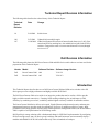
Dell™ PowerConnect™ 5400 and 6200 Series Switches
Using Switches with a PS Series Group
Abstract
This Technical Report describes how to use Dell
PowerConnect 5400 and 6200 series switches with
a PS Series group to create a high performance and
highly available iSCSI SAN.
Copyright © 2008 Dell, Inc.
January 2008
Dell is a registered trademark of Dell, Inc.
All trademarks and registered trademarks mentioned herein are the property of their respective owners.
Possession, use, or copying of the documentation or the software described in this publication is authorized only
under the license agreement specified herein.
Dell, Inc. will not be held liable for technical or editorial errors or omissions contained herein. The information in
this document is subject to change. Your performance can vary.
Dell, Inc. 300 Innovative Way, Suite 301 Nashua, NH 03062
1
2
Table of Contents
Contents
Technical Report Revision Information ............................................................................. 4
Basic Steps ................................................................................................................................ 5
Understanding Switch and Server Recommendations .................................................. 6
Spanning-Tree ........................................................................................................................... 6
Flow Control .............................................................................................................................. 7
Unicast Storm Control ............................................................................................................ 8
Jumbo Frames .......................................................................................................................... 8
Switch Forwarding Modes ..................................................................................................... 9
VLANs .......................................................................................................................................... 9
QoS............................................................................................................................................... 9
PowerConnect 5400 and 6200 Series Switch Configuration ...................................... 10
Configuration Notes .............................................................................................................. 10
Link Aggregation Group (LAG) or Stacking .................................................................... 10
Edge Port STP Configuration .............................................................................................. 11
Configuring Flow Control ..................................................................................................... 12
Disabling Unicast Storm Control ....................................................................................... 13
Configuring Jumbo Frames................................................................................................. 13
Enabling Cut-Through Switch Forwarding ...................................................................... 14
Enabling QoS........................................................................................................................... 14
Documentation and Customer Support ........................................................................... 16
3
Technical Report Revision Information
The following table describes the release history of this Technical Report.
Technical
Report
Revision
Date
Change
1.0
2/04/2008
Initial release.
1.06
2/03/2009
Updated info on multiple topics
1.07
11/09/2009 Added clarification info on PowerConnect Jumbo frame size, LAGs, flow
control and PC62xx stacking bus. Also added info on QoS for the PC62xx
switches. Changed doc name revision to match internal revision (changed
rev6 to rev1.07
Dell Revision Information
The following table shows the Dell PowerConnect 5400 and 6200 Series switch software versions used for the
preparation of this Technical Report.
Vendor Model
Software Revision Software Image Version
Dell
PowerConnect 5400 A00
V1.0.0.31
Dell
PowerConnect 6200 A05
V2.0.0.12
Introduction
This Technical Report describes how to use Dell PowerConnect 5400 and 6200 series switches with a PS
Series group to create a high-performance and highly-available iSCSI SAN.
The Dell PowerConnect 6200 series switch is an innovative product that can be used in a SAN to provide
highly scalable network connectivity. Featuring 10GE stacking technology, the switch improves SAN
efficiency by combining ease-of-use, scalability, and the highest resiliency available for stackable switches.
The PowerConnect 5400 Series delivers wire-speed, Gigabit Ethernet with advanced security and enterprise
management features to meet the needs of organizations of all sizes. In addition to offering a secure, highperformance networking platform and delivering advanced network management features, the PowerConnect
5448 is capable of self-optimization for iSCSI storage traffic.
Dell EqualLogic storage solutions offer a fundamental change in iSCSI SAN implementation. By configuring
PS Series storage arrays into a PS Series group, both large and small businesses can incrementally deploy a
modular and affordable iSCSI SAN solution that easily scales to hundreds of terabytes.
4
Built on ground-breaking, patented architecture, PS Series storage arrays deliver enterprise-quality
performance and reliability for all major operating systems. Intelligent automation and seamless virtualization
of a single pool of group storage greatly simplify storage management. PS Series storage arrays also provide a
comprehensive set of high-level features, in addition to fully redundant, hot-swappable hardware.
Use the recommendations in this Technical Report for proper connectivity and configuration of Dell
PowerConnect 5400 and 6200 series switches and PS Series storage arrays to dramatically improve iSCSI SAN
performance and data availability.
Basic Steps
Follow these recommended basic steps to use Dell PowerConnect 5400 and 6200 series switches with PS
Series storage arrays to create a high-performance and highly-available iSCSI SAN:
1. Set up a PS Series group and create volumes in the group. See the PS Series QuickStart or Group
Administration manual for information. Also, see the Network Connection and Performance Guidelines
Technical Report on the EqualLogic Customer Support website for detailed information about how to
improve performance when using a PS Series group.
2. Set up Dell PowerConnect 5400 and 6200 series switches that will handle iSCSI traffic between servers
and the PS Series group members (storage arrays). Be sure to follow these recommendations, listed in
order of significance. Before changing any switch settings make sure to update the switch firmware to
the absolute latest from the Dell Support site.
• It is recommended that you do not use Spanning-Tree (STP) on switch ports that connect end nodes
(iSCSI initiators or storage array network interfaces). If you want to use STP or RSTP (preferable to
STP), enable Dell’s Port Fast option on each switch port that connects end nodes. Port Fast will
reduce network interruptions that occur when devices restart.
Note that the use of Spanning-Tree for a single-cable connection between switches is encouraged, as is
the use of link aggregation for multiple-cable connections between switches.
• It is recommended that you configure Flow Control on each switch port that handles iSCSI traffic.
PS Series storage arrays will correctly respond to Flow Control if enabled on a switch. If your server
is using a software iSCSI initiator and NIC combination to handle iSCSI traffic, you must also enable
Flow Control on the NICs to obtain the performance benefit.
• It is recommended that you disable unicast storm control on each switch that handles iSCSI traffic.
However, the use of broadcast and multicast storm control is encouraged.
• Configure Jumbo Frames on each switch that handles iSCSI traffic. If your server is using a software
iSCSI initiator and NIC combination to handle iSCSI traffic, you must also enable Jumbo Frames on
the NICs to obtain the performance benefit (or reduce CPU overhead) and ensure consistent behavior.
Notes: Do not enable Jumbo Frames on switches unless Jumbo Frames is also configured on the NICs;
otherwise, behavior may be inconsistent.
To simplify troubleshooting initial deployments, make sure that NICs, switches, and PS Series
5
storage arrays are fully operational before enabling Jumbo Frames on the switches and NICs.
• Use VLANs to separate iSCSI SAN traffic from other network traffic. PS Series storage arrays do
not support VLAN tagging.
• Configure switches that handle iSCSI SAN traffic to prioritize iSCSI traffic with Quality of Service
(QoS) settings.
• Configure switches that handle iSCSI SAN traffic for a cut-though or adaptive forwarding mode.
Detailed information about the previous recommendations is provided later in this document.
3. Set up the servers that will access the PS Series group volumes. Servers require an installed iSCSI
initiator to access group volumes, which are seen on the network as iSCSI targets. A server can use a
software iSCSI initiator and network interface card (NIC) combination or an iSCSI HBA to access group
volumes. See the PS Series QuickStart or Group Administration manual for information about connecting
to volumes. When configuring a software iSCSI initiator and NIC combination on a server, follow these
recommendations:
• It is recommended that you enable Flow Control on each NIC that handles iSCSI traffic. Flow
Control must also be enabled on the switches that handle iSCSI traffic to obtain the performance
benefit.
• Enable Jumbo Frames on each NIC that handles iSCSI traffic. Jumbo Frames must also be enabled
on the switches that handle iSCSI traffic to obtain the performance benefit (or reduce CPU overhead)
and ensure consistent behavior.
Notes: Do not enable Jumbo Frames on NICs unless Jumbo Frames is also configured on the switches
that handle iSCSI traffic; otherwise, behavior may be inconsistent.
To simplify troubleshooting initial deployments, make sure that NICs, switches, and PS Series
storage arrays are fully operational before enabling Jumbo Frames on switches and NICs.
Detailed information about the previous recommendations is provided later in this document.
Understanding Switch and Server Recommendations
The following sections provide more information about the switch and server recommendations for creating a
high-performance and highly-available iSCSI SAN using up Dell PowerConnect 5400 and 6200 series
switches and PS Series storage arrays.
Spanning-Tree
For switch ports that connect end nodes (iSCSI initiators or storage array network interfaces), it is
recommended that you do not use Spanning-Tree (STP). However, if you want to use STP or RSTP
(preferable to STP) for switch ports that connect end nodes, it is recommended that you enable Dell’s Port Fast
option on each switch port. Port Fast will reduce network interruptions that occur when devices restart.
6
Caution: The use of Spanning-Tree for a single-cable connection between switches or the use of link
aggregation for multiple-cable connections between switches is encouraged. Configure
Port Fast only on ports that connect to end stations (initiators and PS Series arrays);
otherwise, an accidental topology loop could cause a data packet loop and disrupt switch
and network operation.
Spanning-Tree Protocol (IEEE 802.1d) is a link management protocol that prevents loops in an Ethernet
network by ensuring that only one active path exists between switches. Upon link up, a switch performs a 30
to 50 second STP calculation to transition ports into forwarding or blocking state. During this time, no user
data passes through the ports. The result is that links will take longer to come online. This can cause long
failover times when recovering from a network switch or PS Series storage array control module failover.
Rapid Spanning Tree Protocol (RSTP; IEEE 802.1w) allows a switch port to bypass the Spanning-Tree
listening and learning states and quickly enter the STP forwarding state. In order to achieve fast convergence
on a port, RSTP relies upon two variables: edge ports and link type. Switch ports connecting end nodes (iSCSI
initiators and storage array network interfaces) should be configured as edge ports to take advantage of RSTP
features. However, do not connect other hubs, switches, concentrators, or bridges to edge ports, because this
may cause infinite packet loops.
Some switches have port settings that allow the immediate transition of the port into STP forwarding state
upon link up. If you are using STP or RSTP, these settings should be enabled on ports that connect end nodes
(iSCSI initiators and storage array network interfaces). For example, the original 802.1d STP specification
was enhanced with a feature called Port Fast, which immediately transitions a port into STP forwarding state
upon link up. If you are using STP or RSTP, switch ports that are connected to end nodes should be configured
as edge ports using the Port Fast command. However, do not connect other hubs, switches, concentrators, or
bridges to these ports, because this may cause infinite packet loops.
See your switch documentation for information on Spanning-Tree, in addition to in this document.
Flow Control
EqualLogic recommends that you enable Flow Control on the switch ports that handle iSCSI traffic. In
addition, if a server is using a software iSCSI initiator and NIC combination to handle iSCSI traffic, you must
also enable Flow Control on the NICs to obtain the performance benefit.
On many networks, there can be an imbalance in the network traffic between the devices that send network
traffic and the devices that receive the traffic. This is often the case in SAN configurations in which many
servers (initiators) are communicating with storage devices. If senders transmit data simultaneously, they may
exceed the throughput capacity of the receiver. When this occurs, the receiver may drop packets, forcing
senders to retransmit the data after a delay. Although this will not result in any loss of data, latency will
increase because of the retransmissions, and I/O performance will degrade.
Flow Control allows the receiver to instruct the sender to “throttle back" when the receiver senses that it is
being overwhelmed by packets. The receiver does this by sending "pause frames" to the sender, which causes
the sender to slow packet transmission for a short period of time. This allows the receiver to process its
backlog so it can later resume accepting input. However, the amount of delay introduced by this action is
dramatically less than the overhead caused by TCP/IP packet retransmission.
See your switch and NIC documentation for information on enabling Flow Control, in addition to Enabling the
Port Fast Option to Configure STP Edge Ports in this document.
7
Unicast Storm Control
A traffic “storm” occurs when a large outpouring of packets creates excessive network traffic that degrades
network performance. Many switches have traffic storm control features that prevent ports from being
disrupted by broadcast, multicast, or unicast traffic storms on physical interfaces. These features typically
work by discarding network packets when the traffic on an interface reaches a percentage of the overall load
(usually 80 percent, by default).
Because iSCSI traffic is unicast traffic and can typically utilize the entire link, it is recommended that you
disable unicast storm control on switches that handle iSCSI traffic. However, the use of broadcast and
multicast storm control is encouraged.
See your switch documentation for information on disabling unicast storm control, in addition to Disabling
Unicast Storm Control in this document.
Jumbo Frames
EqualLogic recommends that you enable Jumbo Frames on the switch ports that handle iSCSI traffic. In
addition, if a server is using a software iSCSI initiator and NIC combination to handle iSCSI traffic, you must
also enable Jumbo Frames on the NICs to obtain the performance benefit (or reduce CPU overhead) and ensure
consistent behavior.
Ethernet traffic is transported in units called frames. A standard Ethernet frame allows up to 1500 bytes of data
to be transferred in a single Ethernet transaction. Jumbo Frames extend Ethernet frames to 9000 bytes and
allow more data to be transferred with each Ethernet transaction.
A PS Series storage array automatically supports standard Ethernet frames and Jumbo Frames up to 9000 bytes
(9018 including the TCP header itself). (This is sometimes referred to as the “Alteon standard.”) PS Series
storage arrays also support path MTU, which is the ability to automatically detect the maximum frame size
between TCP/IP end points.
Note: To take advantage of Jumbo Frames, all devices in the network path between servers and the PS
Series group⎯including the switches and the NICs used to access volumes⎯must have Jumbo Frames
enabled. Switches configured for Jumbo Frames will support both standard Ethernet frames and
Jumbo Frames. However, if a NIC is configured for Jumbo Frames, but the switch is not, you may
experience inconsistent behavior. The switch will function properly if the frames are small, but once
the NIC attempts to send frames larger than 1500 bytes, the switch will not be able to handle the
frames and will drop them. Also, if some switches are configured for Jumbo Frames, but others are
not, you may experience inconsistent behavior if routing changes occur after the connection has been
established.
Many low and mid-range network switches do not support Jumbo Frames. On switches that do support them,
the feature is usually disabled by default, so you need to manually enable it.
Usually, VLANs must be enabled in order to enable Jumbo Frames on switches. See the switch documentation
for details, in addition to Configuring Jumbo Frames in this document.
8
Switch Forwarding Modes
Another impact to performance in switched network could be the forwarding mode in use by your network
switch hardware. The traditional default of store-and-forward mode, which requires an outbound packet from
a switch be entirely available in local buffers before it is sent on, can increase latency and lower performance.
Switching Forwarder modes like cut-through and fragment-free can reduce this latency, albeit at a reliability
cost. Store and Forward mode ensures that the entire CRC is calculated and checked against the packet for
consistency before the packet is forwarded on, whereas cut through and fragment free will start sending the
packet after the first 14 and 64 bytes respectively are read.
If available switch hardware supports multiple packet switching modes, you may consider a change if you are
in a lightly loaded, or private network hardware only for iSCSI traffic. The use of cut-through, fragment free,
or an adaptive mode (that uses all three) can provide additional value in environments with the use of largepayload Jumbo Frame traffic. Depending on your switch hardware, some of these modes may not be available,
or may only function in store-and-forward mode.
VLANs
EqualLogic recommends that you use virtual LANs (VLANs) to enable network switches to separate iSCSI
SAN traffic from other network traffic. VLANs provide benefits similar to those of separate network switches,
but with fewer physical switches and less management overhead. Because VLANs use logical rather than
physical connections, they are flexible to operate.
Note: PS Series storage arrays do not support VLAN tagging. Also do not use VLAN1 for iscsi traffic
(sometimes called the default VLAN) if JUMBO frames will be used as JUMBO frames when used in
this VLAN have been seen to work inconsistently.
Typically, VLANs are separate subnets in TCP/IP networks, so connectivity between VLANs usually requires
L3 routing, which is a capability of the Dell PowerConnect 5400 and 6200 series switches. VLANs also
support different network settings, including Jumbo Frames. See Jumbo Frames for more information.
Separating iSCSI SAN traffic from LAN traffic also allows you to enable switch-based security enhancements,
including port blocking, address filtering, etc.
QoS
Quality of Service (QoS, defined in the IEEE 802.1D, IEEE 802.1Q and IEEE 802.1P standards) is the a
predefined level of performance by raising or limiting the priority of dataflow in a network system. Network
QoS as defined can be implemented at the physical MAC level or the VLAN level depending on the switch
hardware.
If shared network infrastructure is transporting iSCSI traffic to PS Series arrays along with other applications
QoS can be implemented along with VLANs to permit iSCSI data traffic an elevated priority thereby further
improving overall performance.
9
PowerConnect 5400 and 6200 Series Switch Configuration
The following sections provide information about configuring Dell PowerConnect 5400 and 6200 series
switches. For additional information, see:
Dell PowerConnect 5400 switch:
Documentation: http://support.dell.com/support/edocs/network/54xx/
Dell PowerConnect 6200 switch:
Documentation: http://support.dell.com/support/edocs/network/pc62xx/
Configuration Notes
The following examples are for specified use cases for Dell PowerConnect 5400 and 6200 series switches.
Unless otherwise noted, 5400 series interface specific examples generally assume configuration of local
switch-port g1 and 6200 series interface specific examples generally assume switch member 1 on switch-port
g1. Also, unless noted, all examples start assuming the user is in privileged exec mode. The user must also
note that until the running configuration is copied to the startup configuration, all changes are temporary. For
both 5400 and 6200 series switches, this can be accomplished while in privileged exec mode with the
following command.
# copy running-config startup-config
Link Aggregation Group (LAG) or Stacking
If redundant PowerConnect 5400 or 6200 series switches will be used you must enable and create either a LAG
(on the PS54xx or PC62xx switches) or use the Stacking bus feature of the PS62xx series switches. PC6224 or
PC6248 switches are generally purchased and used with the stacking feature since the bandwidth of the
stacking bus is much larger (40GB) than the maximum 8 port LAG that could be created and will not waste
valuable GiGE switch ports. The cost of the stacking bus cables if very minimal compared to the benefit which
is realized using the stacking feature.
Dell recommends if using a LAG that a minimum of at least 70% of the total active ETH ports of all
PS arrays which will be in the group are used for the LAG. This will cover 70% of all iscsi bandwidth
scenarios but a full 100% is suggested to offer a greater chance of avoiding network congestion
issues.
See the Dell PowerConnect switch Administration guide documentation on how to setup a LAG or configure
stacking.
10
Note that placing a single network cable between two switch ports will configure a LAG however this is not
enough to support the PS series bandwidth correctly even though it may allow initial configuration. It is
important to configure the LAG per the documentation prior to adding any more than a single link.
Edge Port STP Configuration
To configure STP edge ports on Dell PowerConnect 5400 and 6200 series switches, you must enable the Port
Fast option. Port Fast minimizes the time that ports must wait for Spanning-Tree to converge and should only
be used on ports connected to end nodes (end stations), including iSCSI initiators and storage array network
interfaces.
Caution: Connecting hubs, concentrators, switches, or bridges to a port that has Port Fast enabled can cause
temporary spanning-tree loops. You should not enable Port Fast on these ports.
The following examples for Dell PowerConnect 5400 and 6200 series switches cover enabling Rapid STP with
Port Fast on the user specified end-point interface. They begin assuming the user is in privileged EXEC mode,
and enable port-fast on local switch port 1.
Dell PowerConnect 5400 Series CLI Example:
# configure
# spanning-tree mode rstp
# interface ethernet g1
# spanning-tree portfast
# end
Dell PowerConnect 6200 Series CLI Example:
# configure
# spanning-tree mode rstp
# interface ethernet 1/g1
# spanning-tree portfast
# end
The following examples for Dell PowerConnect 5400 and 6200 series switches cover disabling
Spanning-Tree on the user specified end-point interface. They begin assuming the user is in
privileged EXEC mode, and disable spanning tree on local switch port 1.
CAUTION: Verify that Spanning-Tree is only disabled on ports that connect directly to end
stations (initiators and PS Series arrays); otherwise, an accidental topology loop
could cause a data packet loop and disrupt switch and network operation.
Dell PowerConnect 5400 Series CLI Example:
# configure
# interface ethernet g1
11
# spanning-tree disable
# end
Dell PowerConnect 6200 Series CLI Example:
# configure
# interface ethernet 1/g1
# spanning-tree disable
# end
For further information regarding specific RSTP and STP configuration, please see your switch
documentation.
Configuring Flow Control
The following examples for Dell PowerConnect 5400 and 6200 series switches cover enabling Flow Control.
Dell PowerConnect 5400 series switches allow flow control to be enabled on the specified end-point interface.
Dell PowerConnect 5400 Series CLI Example:
# configure
# interface ethernet g1
# flowcontrol on
# end
On Dell PowerConnect 6200 series switches, Flow Control is a globally enabled option that is mutually
exclusive with head of line blocking prevention mode.
Dell PowerConnect 6200 Series CLI Example:
# configure
# flowcontrol
# end
Please see your switch model’s documentation for further information regarding specific Flow Control
configuration.
On Dell PowerConnect 5400 and 6200 switches in which a LAG is being used it is very strongly
recommended to also enable flow control on the individual ports that comprise the LAG. If the 6200
stacking bus is being used only, then flow control does not need to be enabled on this bus.
Below is an example of how to enable flow-control on switch ports 21 – 24 that are being used in a
LAG.
console> enable
console# configure
console (config)# interface range ethernet g21,g22,g23,g24
console(config-if)# channel-group 1 mode on
console(config-if)# exit
console(config)# interface port-channel 1
12
console(config-if)# flowcontrol on
console(config-if)# lacp timeout long
console(config-if)# exit
Disabling Unicast Storm Control
This section describes how to disable unicast storm control on Dell PowerConnect 5400 and 6200 series
switches.
The following examples for Dell PowerConnect 5400 and 6200 series switches cover disabling Unicast Storm
Control on the user specified interfaces responsible for passing iSCSI traffic. They begin assuming the user is
in privileged EXEC mode, and disable unicast storm control on local switch port 1.
Dell PowerConnect 5400 Series CLI Example:
# configure
# interface ethernet g1
# no port storm-control include-multicast
# end
Dell PowerConnect 6200 Series CLI Example:
# configure
# interface ethernet 1/g1
# no storm-control unicast
# end
Please see your switch model’s documentation for further information regarding specific packet storm control
configuration.
Configuring Jumbo Frames
On Dell PowerConnect 5400 series switches, you cannot set the MTU size for an individual interface. Instead,
you must set it for all interfaces on the switch. When you change the MTU size, you must reset the switch
before the new configuration takes effect. Remember to copy your running-config to the startup-config prior
to rebooting the switch. On 6200 series ports, Jumbo MTU settings should be enabled on all ports that are
expected to pass iSCSI traffic, this is including non-edge ports such as uplinks and port channels. NOTE: Do
not set Jumbo frames to anything other than 9216 on PC62xx based switches or connection issues will
occur.
The following examples for Dell PowerConnect 5400 and 6200 series switches cover enabling Jumbo Frame
support on switch interfaces. They begin assuming the user is in privileged EXEC mode.
Dell PowerConnect 5400 Series CLI Example:
# configure
# port jumbo-frame
# end
Dell PowerConnect 6200 Series CLI Example:
13
# configure
# interface ethernet 1/g1
# mtu 9216
# end
Please see your switch model’s documentation for further information regarding specific Jumbo Frame support
and configuration.
Enabling Cut-Through Switch Forwarding
The following example for Dell PowerConnect 6200 series switches cover enabling cut-through switching
globally on the switch and begins assuming the user is in privileged EXEC mode.
Note: Cut-through mode does not support passing packets from lower to higher speed network interfaces as it
disrupts the continuous flow of data model. Hence, Dell PowerConnect 6200 series switches can not cutthrough data traffic from 1G to 10G ports, and will instead use store-and-forward in this transaction.
Note: Cut-through mode on the Dell PowerConnect 6200 series switches does not take effect till reboot.
Please remember to copy your running-config to the startup-config prior to rebooting the switch for cutthrough mode to take effect.
Dell PowerConnect 6200 Series CLI Example:
# configure
# cut-through mode
# exit
# copy running-config startup-config
# reload
Please see your switch model’s documentation for further information regarding specific Packet Forward mode
support and configuration.
Enabling QoS
PS series arrays will benefit from QoS settings permitting iSCSI traffic elevated packet priority. The
following examples for Dell PowerConnect 5400 and 6200 series switches cover enabling elevated
QoS support on switch interfaces. Note that if the PowerConnect 62xx switch is running FW
2.2.0.3 or greater, then the below QoS settings are not needed. The below examples begin
assuming the user is in privileged EXEC mode.
Note: The Dell PowerConnect 5400 series switches are iSCSI-aware and provide iSCSI flows with a
QoS profile that ensures that iSCSI endpoints connected via the switch will get a differentiated
service over other network traffic. The configuration settings are applied to the switch globally.
14
However, recently an issue was discovered with this optimization. So until that is resolved in a future
firmware release, you must disable the iSCSI optimization on the 54xx series switch.
Dell PowerConnect 5400 Series CLI Example:
# configure
# no iscsi enable
# end
Note: In the Dell PowerConnect 6200 Series, QoS policies must be attached to each interface
associated with iSCSI traffic, configured to local switch port 1 in this example.
Dell PowerConnect 6200 Series CLI Example:
# configure
# class-map match-all iSCSI
# exit
# class-map match-all iSCSI-tcp3260
# match dstl4port 3260
# match protocol tcp
# exit
# class-map match-all iSCSI-tcp860
# match dstl4port 860
# match protocol tcp
# exit
# policy-map iSCSI-Traffic in
# class iSCSI-tcp3260
# assign-queue 6
# exit
# class iSCSI-tcp860
# assign-queue 6
# exit
#exit
# interface Ethernet 1/g1
# service-policy in iSCSI-Traffic
# end
Please see your switch model’s documentation for further information regarding specific QoS support
and configuration.
15
Documentation and Customer Support
For More Information
For detailed information about PS Series arrays, groups, and volumes see the following
documentation:
•
Release Notes. Provides the latest information about PS Series storage arrays and groups.
•
QuickStart. Describes how to set up the hardware and start using a PS Series storage array.
•
Group Administration. Describes how to use the Group Manager GUI to manage a PS Series group. This
manual provides comprehensive information about product concepts and procedures.
•
CLI Reference. Describes how to use the Group Manager command line interface to manage a group and
individual arrays.
•
Hardware Maintenance. Provides information on maintaining the PS Series storage array hardware.
The QuickStart and Hardware Maintenance manuals are printed and shipped with the PS Series
array.
They are also located on the documentation CD-ROM that is shipped with the array, along with the
Group Administration and CLI Reference manuals and the Group Manager online help.
The Host Integration Tools kit and documentation will be available on the support website
(support.dell.com/EqualLogic) and on a CD-ROM that is shipped with the PS Series array.
Technical Support and Customer Service
Dell's support service is available to answer your questions about PS Series arrays. If you have an
Express Service Code, have it ready when you call. The code helps Dell's automated-support
telephone system direct your call more efficiently.
Contacting Dell
Dell provides several online and telephone-based support and service options. Availability varies by
country and product, and some services may not be available in your area.
For customers in the United States, call 800-945-3355.
Note: If you do not have an Internet connection, you can find contact information on your purchase
invoice, packing slip, bill, or Dell product catalog.
To contact Dell for sales, technical support, or customer service issues:
16
1. Visit support.dell.com.
2. Verify your country or region in the Choose A Country/Region drop-down menu at the bottom of
the window.
3. Click Contact Us on the left side of the window.
4. Select the appropriate service or support link based on your need.
5. Choose the method of contacting Dell that is convenient for you.
Online Services
You can learn about Dell products and services on the following websites:
• www.dell.com/
• www.dell.com/ap/ (Asian/Pacific countries only)
• www.dell.com/jp (Japan only)
• www.euro.dell.com (Europe only)
• www.dell.com/la (Latin American countries)
• www.dell.ca (Canada only)
You can access Dell Support through the following websites:
• support.dell.com
• support.dell.com/EqualLogic
• support.jp.dell.com (Japan only)
• support.euro.dell.com (Europe only)
17