1
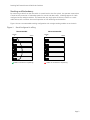
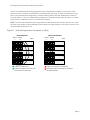
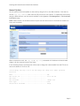
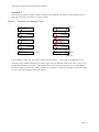
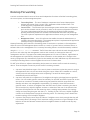
Stacking Dell PowerConnect
6200 Series Switches
A Dell Technical White Paper
www.dell.com │ support.dell.com
Stacking Dell PowerConnect 6200 Series Switches
THIS WHITE PAPER IS FOR INFORMATIONAL PURPOSES ONLY, AND MAY CONTAIN TYPOGRAPHICAL
ERRORS AND TECHNICAL INACCURACIES. THE CONTENT IS PROVIDED AS IS, WITHOUT EXPRESS OR
IMPLIED WARRANTIES OF ANY KIND.
© 2010 Dell Inc. All rights reserved. Reproduction of this material in any manner whatsoever without
the express written permission of Dell Inc. is strictly forbidden. For more information, contact Dell.
Dell, the DELL logo, and the DELL badge, PowerConnect, and OpenManage are trademarks of Dell Inc.
Other trademarks and trade names may be used in this document to refer to either the entities
claiming the marks and names or their products. Dell Inc. disclaims any proprietary interest in
trademarks and trade names other than its own.
PC6224, PC6224P, PC6224F, PC6248, PC6248P
December 2010
Page ii
Stacking Dell PowerConnect 6200 Series Switches
Contents
Introduction ................................................................................................................ 2
Applicability ............................................................................................................. 2
Stacking and Management ............................................................................................ 2
Stacking and Performance ............................................................................................ 2
Stacking and Redundancy ............................................................................................. 3
Power-Up Sequencing Considerations ............................................................................... 5
Initial Installation and Power-up of a Stack .......................................................................... 6
Selecting the Master Unit ................................................................................................ 7
Selecting the Standby Unit .............................................................................................. 7
Updating the Firmware on a Stack ..................................................................................... 8
Automatic Update ...................................................................................................... 8
Manual Update .......................................................................................................... 9
Creating a Separate VLAN for File Downloads ................................................................... 10
Adding a Stack Member with Minimal Interruption ................................................................ 13
Removing a Stack Member with Minimal Interruption ............................................................ 14
Merging Two Operational Stacks ...................................................................................... 15
Synchronizing the Running Configuration Between the Master and Standby Units .......................... 15
Master Failover .......................................................................................................... 15
Effect of Master Failover on PoE Devices......................................................................... 15
Stack Member Failover ................................................................................................. 16
Failover Scenarios ....................................................................................................... 16
Scenario 1 .............................................................................................................. 16
Scenario 2 .............................................................................................................. 17
Scenario 3 .............................................................................................................. 18
Nonstop Forwarding ..................................................................................................... 19
Initiating a Warm Failover of the Manager Unit ................................................................. 20
Nonstop Forwarding Scenario....................................................................................... 20
NSF Scenario Configuration via CLI ............................................................................. 22
NSF Example 1 ...................................................................................................... 26
NSF Example 2: ..................................................................................................... 26
NSF Reconvergence Timing ............................................................................................ 27
Medium Configuration .................................................................................................. 27
Small Configuration ..................................................................................................... 28
Stacking CLI Commands ................................................................................................ 28
Stacking Web Interface ................................................................................................. 29
Summary .................................................................................................................. 29
Page 1
Stacking Dell PowerConnect 6200 Series Switches
Introduction
This white paper explains the purpose and operation of the stacking feature in the Dell™
PowerConnect™ 6200 Series Gigabit Ethernet switches. The PowerConnect 6200 series is Dell’s most
advanced switching product line, offering advanced switching capabilities including high-density, highperformance stacking, and 10 Gigabit Ethernet capabilities that scale from the small business to the
Enterprise Edge. Stacking allows multiple switching units to be combined together to act as a single,
high-performance, highly resilient switching unit with a single management interface. Units can be
added to increase throughput as needed. With each stack unit supporting up to 184 Gbps in switch
capacity, the customer can have almost 2 terabits of capacity in a single stack.
Applicability
This paper applies to the PowerConnect 6200 series switches, which includes the PC6224, PC6248,
PC6224P, PC6248P, and PC6224F Dell part numbers. Each PowerConnect switch has two bays that can
be customized to support a stacking or an uplink configuration. Bay 1 can contain a stacking, CX-4 or
SFP+ module. Bay 2 can contain a CX-4, SFP+, or 10GBase-T module. Stacking is supported only on CX-4
or stacking modules in either bay and must be enabled by the operator. The switch supports mixing CX4 and stacking modules together in a stack. Whether using a stacking module or a CX-4 module
configured for stacking, the maximum cable length that can be used for stacking is 3 meters.
Stacking and Management
An important advantage of stacking is that it provides a consolidated interface for management of
multiple switches when linked together. When a stack is already deployed in the network, operators
can add units to the stack as their port requirements increase, with minimal administrative overhead
required for reconfiguration. Additional stack members can immediately utilize existing configuration
information such as routing and switching configurations, VLANs, ACLs, port profiles, and security
certificates.
Stacking and Performance
For situations where there is a need to pass traffic between switches and the aggregate bandwidth
required between PowerConnect 6200 Series switches does not exceed 48 Gbps (2 ports, 12 Gbps Tx
and Rx each), a stacking configuration offers an attractive alternative to Link Aggregation Groups
(LAGs). Stacking configuration is generally transparent to the operator and does not require
configuration beyond cabling. In addition, failover times are generally faster in a stack configuration.
Stacking operates over CX-4 or stacking modules in either bay. Note that other PowerConnect Series
switches may have different supported bandwidths for stacking.
Page 2
Stacking Dell PowerConnect 6200 Series Switches
Stacking and Redundancy
By connecting a cable from the last switch in a stack back to the first switch, the operator ensures that
a stack has the protection of redundant paths for control and data traffic, including support for LAGs
configured across multiple switches. This means that any single point of failure (a switch or a stack
cable failure) will not affect the overall operation of the remaining stack elements.
Figure 1 shows a recommended stacking configuration with a single stacking module on each switch.
Figure 1.
Stack Configured in a Ring
Recommended
Module
A
Not recommended
Switch
Module
A
Switch
1
1
2
2
3
3
4
4
5
5
aCables connected in a complete ring.
r
Cables not connected in a complete ring.
Page 3
Stacking Dell PowerConnect 6200 Series Switches
0 shows a recommended stacking configuration with a dual stacking modules on each switch. Each
switch connects to another with 96 Gbps of total bandwidth (4 ports @ 12 Gbps Tx and Rx each). Note
that in the recommended configuration, the dual stacking cables from each module both connect to
the same switch. In the not-recommended configuration, the dual stacking cables on switch 2, module
B and switch 3, module B connect to two different switches.
NOTE: To ensure full bandwidth when using redundant links between two switches, be sure not to split
the links across modules. Keep redundant links isolated to a single module on each end as shown in the
recommended configuration in 0.
Figure 2.
Dual Stacking Modules Configured in a Ring
Recommended
Module
A
Module
B
Not recommended
Switch
Module
B
Switch
1
1
2
2
3
3
4
4
5
5
aCables connected in a ring.
aDual stacking cables connect both ports
on a module to the same switch.
Module
A
r
Cables not connected in a complete ring.
r
Dual stacking cables connect ports on a module to
two different switches.
Page 4
Stacking Dell PowerConnect 6200 Series Switches
Power-Up Sequencing Considerations
The selection of the manager and standby units is important in situations where the administrator
wishes to utilize the serial port for management, perhaps as a backup console. Management of the
stack via the out-of-band port or the in-band ports is transparent in a stack.
In a stacking configuration, the power-up sequence determines the manager and standby units. The
switch that the operator selects as the manager should be powered up first and should be allowed to
fully come up. The standby switch should always be directly connected to the manager. Once the
manager and standby have powered up fully, other members of the stack can be powered on
sequentially by powering up the switch adjacent to the last switch powered on.
A stack of units is managed and acts as a single entity when the units are connected together and are
operational. If a unit cannot detect a stacking partner, the unit automatically operates as a stack of 1
with itself as the Master. If a stacking partner is detected, the switch always operates in stacking
mode. One unit in the stack is elected as the Master unit. The Master manages all the units in the
stack. A second switch is elected as the Standby unit, which becomes the Master if the Master unit is
unavailable. The administrator can manually configure which unit is elected as the Standby, or the
system can select the Standby automatically.
NOTE: The terms “Master” and “Manager/Management Unit” are used interchangeably throughout this
document.
When units are operating together as a stack, the following activities occur:
•
•
•
All units are checked for software version consistency on startup. If configured by the
operator, units with old versions of software are automatically updated to the latest
version as they join the stack.
Switch management and protocols such as OSPF are active only on the Master. Unless
administratively disabled, the Nonstop Forwarding (NSF) feature periodically
checkpoints the running configuration and the application state between the Master
and Standby switches during normal stacking operation. If the Master fails, the Standby
switch takes over operation of the stack.
Data forwarding is active on all units in the stack, including the Master. Data
forwarding continues to operate should the master become unavailable.
Page 5
Stacking Dell PowerConnect 6200 Series Switches
Initial Installation and Power-up of a Stack
Follow these instructions to create a stack:
NOTE: Install units in a rack whenever possible to prevent the units and cables from being disturbed.
1. Install all stacking cables. Fully connect all cables, including the redundant stack link.
CAUTION! We highly recommend that a redundant link be installed to provide stack resiliency.
2. Select a unit to be the manager unit. Power this unit up first.
3. Monitor the console port on the manager unit. The unit will automatically become a Manager
unit. If not, renumber the unit as desired.
4. If desired, preconfigure other units to be added to the stack.
5. Power on a second unit, making sure it is adjacent (directly connected) to the unit already
powered up. This ensures the second unit comes up as a member of the stack, not as the
Manager of a separate stack.
6. Monitor the Manager unit to see that the second unit joins the stack. Use the show switch
command to determine when the unit joins the stack. It will be assigned a unit number (unit
#2, if it has the default configuration). The output of the show switch command should
indicate the unit status as “OK” if the member has been successfully added to the stack. If the
unit status is "code mismatch" and stack auto-upgrade is disabled, then use the copy image
unit command to update the code on the unit. If the unit status is "Cfg Mismatch", then use
the no member <unit-number> command to resolve the issue.
7. If desired, renumber this stack unit using the switch renumber command.
8. Repeat steps 4 through 6 to add additional members to the stack. Always power on a unit
directly connected to the units already in the stack.
9. Enter the show stack-port counters command on the manager and see if there are any
stack port errors being reported. Replace the stacking cables/modules in case stack errors are
being reported and begin the power-up sequences again for the affected units and any
downstream units.
Page 6
Stacking Dell PowerConnect 6200 Series Switches
Selecting the Master Unit
A stack manager is elected or re-elected based on the following considerations, in order:
• Whether the switch that was previously the stack manager.
• Whether the switch has the higher MAC address.
When you add a switch to the stack, one of the following scenarios takes place:
•
If the switch has the Management Unit function enabled but another Master unit is
already active, then the switch changes its configured Management Unit value to
disabled.
• If the Management Unit function is unassigned and there is another Management Unit in
the system then the switch changes its configured Management Unit value to disabled.
• If the Management Unit function is enabled or unassigned and there is no other
Management Unit in the system, then the switch becomes Management Unit.
• If the Management Unit function is disabled, the unit remains a non-management unit.
You can manually set the unit number for the switch. To avoid unit-number conflicts, one of the
following scenarios takes place when you add a new member to the stack:
•
If the switch has a unit number that is already in use, then the unit that you add to the
stack changes its configured unit number to the lowest unassigned unit number.
• If the switch you add does not have an assigned unit number, then the switch sets its
configured unit number to the lowest unassigned unit number.
• If the unit number is configured and there are no other devices using the unit number,
then the switch starts using the configured unit number.
• If the switch detects that the stack already has the maximum number of units, making
it unable to assign a unit number, then the switch sets its unit number to “unassigned”
and does not participate in the stack.
If a new switch is added to a stack of switches that are already powered and running and already have
an elected Master unit, the newly added switch becomes a stack member rather than the Master. On
the Master unit, if there is no saved configuration for the newly added unit, it applies the default
configuration. If there is a saved configuration on the Master for the newly added unit, it would apply
the saved configuration to the new unit. If the entire stack is powered OFF and ON again, the unit that
was the Master before the reboot will remain the Master unit after the stack resumes operation.
Selecting the Standby Unit
When the stack is formed, one of the units is automatically selected as the Standby unit for the stack.
The Standby unit takes over as Manager if the current Manager fails.
To configure the Standby unit using the CLI, use the standby unit-number command in Stack
Configuration Mode.
To configure the Standby unit via the Web interface, view the Stacking > Unit Configuration page and
select Standby for the Unit Type.
Page 7
Stacking Dell PowerConnect 6200 Series Switches
Updating the Firmware on a Stack
Automatic Update
By default, firmware synchronization is not performed automatically when a unit is powered up on a
stack. Because firmware synchronization makes no attempt to check for the latest version of firmware,
the following procedure is recommended for bringing all members of a stack onto the same version of
code.
NOTE: Schedule some downtime as this process will reset the entire stack and affect all stack users.
1. Enable firmware synchronization using the boot auto-copy-sw command. Write the running
configuration to the saved configuration.
2. Load the more recent firmware image onto the stack master.
3. Set the stack master to reboot from the new image using the boot system image command.
4. Reload the stack using the reload command. This resets the entire stack.
5. When the stack has reloaded, check the running firmware version using the show boot-var
command. Check that all stack members have joined the stack using the show stack
command. Members that failed to update may be recovered using the manual update
procedure described in the following section.
6. If successful, disable firmware synchronization on the stack and save the running configuration.
Page 8
Stacking Dell PowerConnect 6200 Series Switches
Manual Update
You can perform firmware updates on the stack by using the CLI or the Web interface. From the CLI,
use the copy ftp command, which uses the FTP protocol for file transfer. To update the firmware by
using the Web interface, use the options available on the System > File Management > File Download
from Server page.
NOTE: When stacked, the PC6200 switches require that the same version of firmware be installed on
every switch member.
When connected in stack, the copy ftp or copy tftp commands will distribute the downloaded
image to all the connected units of the stack.
In the following output, the image with a file name of image.stk is downloaded from the FTP server
with an IP address of 10.27.64.141.
console#copy ftp ftp://10.27.64.141/image.stk image user admin password
test1234
Mode...........................................
FTP Server IP..................................
FTP Path.......................................
FTP Filename...................................
Data Type......................................
Destination Filename...........................
FTP
10.27.64.141
/image.stk
Code
image
Page 9
Stacking Dell PowerConnect 6200 Series Switches
Creating a Separate VLAN for File Downloads
When updating the firmware, it is helpful to keep the network port in a different VLAN and configure
the PVID appropriately to avoid any network congestion or flooding issues through which the file is
being downloaded.
The CLI commands in the following example show how to configure port 1/g17 as a network port for
firmware downloads or management access.
configure
vlan database
vlan 1000
exit
ip address dhcp
ip address vlan 1000
interface ethernet 1/g17
switchport mode general
switchport general pvid 1000
switchport general allowed vlan add 1000
switchport general allowed vlan remove 1
exit
exit
The switch now uses VLAN 1000 as the management VLAN. Port 1/g17 is assigned to the VLAN, and all
untagged packets that enter the port are tagged with a VLAN ID of 1000.
To perform the same configuration by using the Web interface, use the following steps:
1. From the Switching > VLAN > VLAN Membership page, click Add.
Page 10
Stacking Dell PowerConnect 6200 Series Switches
2. From the Add VLAN page, enter 1000 in the VLAN ID field and click Apply Changes.
1000
3. From the Ports menu on the Switching > VLAN > Port Settings page, select port g20.
4. Configure port g20 in General mode with a PVID of 1000 and click Apply Changes.
g17
1000
5. From the Show VLAN menu on the Switching > VLAN > VLAN Membership page, select 1000.
6. Click the Static box for port 17 so that the letter U (untagged) appears in the box.
Page 11
Stacking Dell PowerConnect 6200 Series Switches
7. Click Apply Changes.
8. Navigate to the System > IP Addressing > Management Interface page.
9. In the Management VLAN ID field, enter 1000.
10. Click Apply Changes.
Page 12
Stacking Dell PowerConnect 6200 Series Switches
Adding a Stack Member with Minimal Interruption
When adding a new member to a stack, make sure that only the stack cables and no network cables are
connected before powering up the new unit. Make sure the end-user links are not connected to any
ports on the unit being added and the new member is powered off. This is important because if STP is
enabled and any links are UP, then STP reconvergence will take place as soon as the link is detected.
After the stack cables on the new member are connected to the stack, you can connect the power. Do
not connect a new member to the stack while the new member is powered up. Also, do not connect
two functional, powered-up stacks together. If you connect two functional, powered-up stacks
together or connect a powered-up new member to the stack, then master re-election takes place and
causes one of the stacks to reboot to resolve this issue. See “Merging Two Operational Stacks” for more
details.
If there are any unassigned units already configured on the stack, remove them prior to adding a new
unit to stack. This is important because when there is any preconfigured unit and the Master holds
some configuration for that unit, as soon as the new unit is detected, the configuration is applied,
which might trigger the reconvergence or startup of many other protocols. However, it is possible to
intentionally preconfigure a unit. You can view the preconfigured/unassigned units by using the show
switch CLI command.
The following example shows how to view the units in the stack and remove an unassigned unit:
console#show switch
SW
--1
2
Management Standby
Status
Status
---------- --------Mgmt Sw
Unassigned
Preconfig
Model ID
------------PCT6224P
PCT6224P
Plugged-in
Model ID
------------PCT6224P
Switch
Status
------------OK
Not Present
Code
Version
---------3.2.0.7
0.0.0.0
console#configure
console(config)#stack
console(config-stack)#no member 2
console(config-stack)#exit
console(config)#exit
Page 13
Stacking Dell PowerConnect 6200 Series Switches
Removing a Stack Member with Minimal Interruption
NOTE: This migration process can be disruptive, so schedule some outage time. To minimize the
disruption, plan on having one or more test scenarios to verify that the migrated ports are operating.
1. Migrate end-user ports to appropriately configured ports on a different stack member. Verify
that the migrated end-user services are operational. If an end user is not operational, it is
possible to recover quickly by connecting the end user back to the original port.
2. Migrate any trunk ports to an appropriately configured port on a different stack member. Verify
the operation of the new trunk port. This may require several steps:
a. Remove spanning tree configuration from the ports on the stack member to be
removed.
b. Remove LAG configuration from the ports on the stack member to be removed.
c. Reroute any statically routed traffic going through the stack member.
3. Remove the member from the stack, re-cable around the member, checking that the cabling is
positively connected and does not show stacking errors. Power off the removed member.
To remove a switch from the stack by using the Web interface, navigate to the System > Stacking >
Unit Configuration page. Select the switch to remove from the Switch ID menu, and then select the
Remove Switch option. Then, click Apply Changes.
Page 14
Stacking Dell PowerConnect 6200 Series Switches
Merging Two Operational Stacks
The recommended procedure for merging two operational stacks is as follows:
1. Always power off all units in one stack before connecting to another stack.
2. Add the units as a group by unplugging one stacking cable in the operational stack and
physically connecting all unpowered units.
3. Completely cable the stacking connections, making sure the redundant link is also in place.
Two operational stacks can also be merged by reconnecting stack cables without powering down units
in either stack. Connecting a powered-up standalone unit to an existing stack leads to same behavior as
when merging two operational stacks. In such cases, Manager re-election is done and the Manager with
the higher MAC address wins the election. The losing stack manager resets itself and all its member
units. After the reset, all the losing stack members join the winning stack to form a single stack. The
winning stack remains functional through the merge process. If the stack merge is performed in this
way, then it is strongly recommended that the user set the admin management preference of the
desired winner stack manager to a higher value than the stack manager that should lose the election.
Synchronizing the Running Configuration Between the
Master and Standby Units
The Master unit copies its running configuration to the Standby unit whenever the configuration
changes (subject to some minimal time delays introduced in the copy mechanism to increase the
efficiency of the transfer process). This enables the Standby unit to take over the stack operation with
minimal interruption if the Master unit becomes unavailable.
The running-config synchronization also occurs:
•
•
When the administrator saves the running configuration to the startup configuration on
the Master unit.
When the Standby unit changes.
Master Failover
If the current Master unit fails, the Standby unit becomes the Master unit. If no switch is preconfigured
as the Standby unit, the software automatically selects a Standby unit from the existing stack units.
When the failed Master resumes normal operation, it joins the stack as a member (not a Master) if the
new Master unit has already been elected.
The stack supports nonstop forwarding and graceful restart during a master failover. See “Nonstop
Forwarding” on page 19.
Effect of Master Failover on PoE Devices
Stack members that provide power-over-Ethernet (PoE) to connected devices continue to provide
power in the event of a master failover. The PoE application uses a separate controller on each unit,
and these controllers are not initialized upon a warm restart.
Page 15
Stacking Dell PowerConnect 6200 Series Switches
If PoE is enabled on a switch port shortly before a master failover and the hardware status change had
not yet been communicated to the backup unit, the switch will continue to provide PoE power even
though PoE is not enabled for the port in the configuration on the new master. The user can correct
this configuration mismatch by re-enabling PoE on the port.
Stack Member Failover
When a unit in the stack fails, the Master unit removes the failed unit from the stack. No changes or
configuration settings are applied to the other stack members; however, dynamic protocols will try to
reconverge as the topology could change because of the failed unit. When there are no connected
ports on the failed unit, the stack will be intact without any changes.
Failover Scenarios
This section describes examples of what happens when a stack member or the Master unit fails.
Scenario 1
In this example, the stack has four members that are connected through a daisy-chain. When all four
units are up and running, the show switch CLI command gives the following output:
console#show switch
Management
Switch Status
------ -----------1
stack Member
2
Stack Member
3
Mgmt Switch
4
Stack Member
Standby
Status
------------Standby
Preconfig
Model ID
--------PCT6248
PCT6248
PCT6248
PCT6248
Plugged-in
Model ID
-------PCT6248
PCT6248
PCT6248
PCT6248
Switch
Status
-----------OK
OK
OK
OK
Code
Version
-------9.19.0.2
9.19.0.2
9.19.0.2
9.19.0.2
At this point, if Unit 2 is powered off or rebooted due to an unexpected failure, show switch gives the
following output:
console#show switch
Switch
-----1
2
3
4
Management
Status
-----------stack Member
Unassigned
Mgmt Switch
Stack Member
Standby
Status
-----------Standby
Preconfig
Model ID
--------PCT6248
PCT6248
PCT6248
PCT6248
Plugged-in
Model ID
----------PCT6248
PCT6248
PCT6248
Switch
Status
-----------OK
Not Present
OK
OK
Code
Version
-------9.19.0.2
0.0.0.0
9.19.0.2
9.19.0.2
When the failed unit resumes normal operation, the previous configuration that exists for that unit is
reapplied by the Master unit.
Page 16
Stacking Dell PowerConnect 6200 Series Switches
Scenario 2
Consider the same example with a four-unit stack connected in daisy-chain fashion.
Figure 3.
Stack Split
Stack 1
Switch 1
Switch 2
Switch 1
Standby
Switch 2
Switch 3
Switch 3
Switch 4
Switch 4
Master
Stack 2
If the link between Switch 2 and Switch 3 is removed, the stack is split into two different stacks with
Switches 1 and 2 in one stack and Switches 3 and 4 in another.
The Master unit for each stack is determined by the following criteria:
•
Switch 3 was configured as Master prior to the split, so it will continue to be the Master
unit for Stack 2 (units 3 and 4).
• If Switch 2 is configured as the Standby, it becomes the Master for Stack 1 (units 1 and
2).
• If none of the units in Stack 1 are configured as Master or Standby, then Stack 1 will
have no Master after the split. The election process will start on these two units, and
either Switch 1 or Switch 2 will come up as a master based on which switch has the
highest base MAC address.
In this specific example, there will not be any change in the configuration in Stack 2. Stack 1 will come
up with the previously saved configuration on the new Master elected.
Note that stack splits are less likely when the switches are cabled in a ring. For example, if Switch 4
was connected to Switch 1 and the link between Switch 2 and Switch 3 was removed, all switches
would remain members of the single stack with Switch 3 continuing as the Master.
Page 17
Stacking Dell PowerConnect 6200 Series Switches
Scenario 3
The following example contains a similar condition with a Master unit failover and consequent stack
split with five units in the stack, as Figure 4 shows.
Figure 4.
Stack Split with Manager Failure
Switch 1
Switch 1
Switch 2
Switch 2
Switch 3
Switch 3
Switch 4
Switch 4
Switch 5
Standby
Switch 5
Stack 1
Master
Stack
In this example, there is no link back to Switch 5 from Switch 1. In this case, if the Manager of the
stack goes down (failed/rebooted), the stack is split into two different stacks with units 1 and 2 in one
stack and units 4 and 5 in another. With this condition, none of the stacks will have a working Master
within the stack, so both of the stacks will elect new masters for each stack through the process based
on which unit has the highest base MAC address.
Page 18
Stacking Dell PowerConnect 6200 Series Switches
Nonstop Forwarding
A switch can be described in terms of three semi-independent functions called the forwarding plane,
the control plane, and the management plane:
•
Forwarding Plane — The set of hardware components that forward data packets
without intervention from a control CPU, sometimes called the Data Plane. The
forwarding plane is implemented in hardware.
• Control Plane — The software layer that manages system and hardware configuration
and runs the network control protocols in order to set system configuration and state.
The control plane determines how the forwarding plane should forward packets,
deciding which data packets are allowed to be forwarded and where they should go.
The control plane is implemented in application software running on the management
unit.
• Management Plane — A set of interfaces that enable the network administrator to
configure the networking device. The management plane is implemented in application
software running on the management unit.
Nonstop forwarding (NSF) allows the forwarding plane of stack units to continue to forward packets
while the control and management planes restart as a result of a power failure, hardware failure, or
software fault on the management unit. A nonstop forwarding failover can also be manually initiated
using the initiate failover command. Traffic flows that enter and exit the stack through physical
ports on a unit other than the management continue with virtually no interruption when the
management unit fails. To prepare the standby management unit in case of a failover, applications on
the management unit periodically checkpoint state information to the standby unit. Changes to the
running configuration are automatically copied to the standby unit. MAC addresses stay the same across
a nonstop forwarding failover so that neighbors do not have to relearn them.
For NSF to be effective, adjacent networking devices must not reroute traffic around the restarting
device. Three techniques are used to prevent traffic from being rerouted:
1. A protocol may distribute a part of its control plane to stack units so that the protocol can give
the appearance that it is still functional during the restart. When NSF is enabled on a switch,
various protocols and configurations such as Spanning Tree and Link Access groups
automatically use this technique.
2. A protocol may enlist the cooperation of its neighbors through a technique known as graceful
restart. You can enable graceful restart functionality for the OSPF and OSPFv3 protocols so that
the stack can continue to forward packets using the same IPv4 and IPv6 routes while the
Standby unit takes over management responsibility. For example, when OSPF executes a
graceful restart, it informs its neighbors that the OSPF control plane is restarting, but that it
will be back shortly. Helpful neighbors continue to advertise to the rest of the network that
they have full adjacencies with the restarting router, avoiding announcement of a topology
change and everything that goes with that (i.e., flooding of LSAs, SPF runs). Helpful neighbors
continue to forward packets through the restarting router. The restarting router relearns the
network topology from its helpful neighbors.
3. A protocol may simply restart after the failover if neighbors react slowly enough that they will
not normally detect the outage. The IP multicast routing protocols are a good example of this
behavior in that the PIM stack restarts before its neighbors detect its absence and drop any
adjacencies.
Page 19
Stacking Dell PowerConnect 6200 Series Switches
To take full advantage of nonstop forwarding, layer 2 connections to neighbors should be via port
channels that span two or more stack units, and layer 3 routes should be ECMP routes with next hops
via physical ports on two or more units. The hardware can quickly move traffic flows from port channel
members or ECMP paths on a failed unit to a surviving unit.
Initiating a Warm Failover of the Manager Unit
You can use the initiate failover command to initiate a "warm" restart. This command reloads
the management unit, triggering the standby unit to take over. As the standby management unit takes
over, the system continues to forward end-user traffic. The end-user data streams switched over the
failing switch may lose a few packets during the failure, but they do not lose their IP sessions, such as
VoIP calls.
If no standby unit is available when the initiate failover command is issued, the command fails
with an error message stating that no standby unit exists. If the standby unit is not ready for a warm
restart, the command fails with a similar error message. The movemanagement command triggers a
cold restart, even if the target unit is the backup unit.
Nonstop Forwarding Scenario
Figure 5 depicts the following network setup:
•
•
Host 1 is a video stream server. Hosts 2 and 3 are video stream receivers.
The stack has OSPF and PIM-SM adjacencies with Router 1 over a LAG with member
ports in unit 1 and unit 2.
• Spanning tree runs on the links in the L2 network connecting the stack, Switch 1, and
Switch 2.
• The stack runs IGMP on the links toward Host 2 and Host 3.
• VLAN 20 is a routing VLAN with IP address 192.168.20.2 on the stack.
• The network is configured to select Switch 2 as the root bridge. The stack selects its
direct link to Switch 2 as its root port. The stack puts its link to Switch 1 in the
Discarding state.
• Router 1 is a Cisco router that serves as a static rendezvous point (RP) in the PIM-SM
network.
The CLI for configuring this scenario follows the illustration, along with a description of how the stack
responds during a failover with NSF enabled and disabled.
Page 20
Stacking Dell PowerConnect 6200 Series Switches
Figure 5.
Nonstop Forwarding Example
Host 1
Video
stream
192.168.5.100
Router 1
OSPF
PIM-SM
VLAN 10
1
2
3
Spanning
Tree
IGMP
VLAN 20
Switch 1
Switch 2
192.168.20.100
Host 2
192.168.20.101
Host 3
Page 21
Stacking Dell PowerConnect 6200 Series Switches
NSF Scenario Configuration via CLI
Router 1:
hostname Router_1
ip routing
ip multicast-routing distributed
ip pim rp-address 192.168.10.1
interface Port-channel1
switchport trunk native vlan 10
switchport trunk encapsulation dot1q
switchport mode trunk
interface GigabitEthernet 1/0/1
no switchport
ip address 192.168.5.1 255.255.255.0
ip pim sparse-mode
interface GigabitEthernet1/0/10
switchport trunk native vlan 10
switchport trunk encapsulation dot1q
switchport mode trunk
no cdp enable
channel-group 1 mode active
interface GigabitEthernet1/0/20
switchport trunk native vlan 10
switchport trunk encapsulation dot1q
switchport mode trunk
no cdp enable
channel-group 1 mode active
interface Vlan1
no ip address
shutdown
!
interface Vlan 10
ip address 192.168.10.1 255.255.255.0
ip pim sparse-mode
!
router ospf 1
router-id 1.1.1.1
log-adjacency-changes
network 192.168.0.0 0.0.255.255 area 0
!
-----------------------------------------
Page 22
Stacking Dell PowerConnect 6200 Series Switches
Stack:
configure
vlan database
vlan 10,20
exit
hostname "nsf-stack"
ip address dhcp
logging console error
ip routing
ip igmp
ip pimsm
ip multicast
ip pimsm rp-address 192.168.10.1 224.0.0.0 240.0.0.0
interface vlan 10
routing
ip address 192.168.10.2
ip igmp
ip igmp version 2
ip pimsm
exit
interface vlan 20
routing
ip address 192.168.20.2
ip igmp
ip igmp version 2
ip pimsm
exit
255.255.255.0
255.255.255.0
spanning-tree mode mstp
router ospf
router-id 2.2.2.2
network 192.168.0.0 0.0.255.255 area 0.0.0.0
nsf
exit
!
interface ethernet 1/g10
switchport mode general
switchport general pvid 10
switchport general allowed vlan add 10
switchport general allowed vlan remove 1
channel-group 1 mode auto
exit
!
interface ethernet 2/g10
switchport mode general
Page 23
Stacking Dell PowerConnect 6200 Series Switches
switchport general pvid 10
switchport general allowed vlan add 10
switchport general allowed vlan remove 1
channel-group 1 mode auto
exit
!
interface ethernet 2/g20
switchport mode general
switchport general pvid 20
switchport general acceptable-frame-type tagged-only
switchport general allowed vlan add 20 tagged
switchport general allowed vlan remove 1
exit
!
interface ethernet 3/g20
switchport mode general
switchport general pvid 20
switchport general acceptable-frame-type tagged-only
switchport general allowed vlan add 20 tagged
switchport general allowed vlan remove 1
exit
!
!
interface port-channel 1
spanning-tree disable
switchport mode general
switchport general pvid 10
switchport general allowed vlan add 10
switchport general allowed vlan remove 1
exit
exit
Switch 1
config
hostname Switch-1
vlan database
vlan 20
exit
spanning-tree mode mstp
spanning-tree priority 16384
interface ethernet 1/g20
switchport mode general
switchport general pvid 20
switchport general acceptable-frame-type tagged-only
switchport general allowed vlan add 20 tagged
switchport general allowed vlan remove 1
Page 24
Stacking Dell PowerConnect 6200 Series Switches
exit
interface ethernet 1/g1
switchport mode access
switchport access vlan 20
exit
interface ethernet 1/g5
switchport mode general
switchport general pvid 20
switchport general acceptable-frame-type tagged-only
switchport general allowed vlan add 20 tagged
switchport general allowed vlan remove 1
exit
exit
Switch 2
Config
hostname Switch-2
vlan database
vlan 20
exit
spanning-tree mode mstp
spanning-tree priority 12288
interface ethernet 1/g20
switchport mode general
switchport general pvid 20
switchport general acceptable-frame-type tagged-only
switchport general allowed vlan add 20 tagged
switchport general allowed vlan remove 1
exit
interface ethernet 1/g1
switchport mode access
switchport access vlan 20
exit
interface ethernet 1/g5
switchport mode general
switchport general pvid 20
switchport general acceptable-frame-type tagged-only
switchport general allowed vlan add 20 tagged
switchport general allowed vlan remove 1
exit
exit
Page 25
Stacking Dell PowerConnect 6200 Series Switches
NSF Example 1
Assume Unit 1 is the Stack Manager and Unit 2 is the Standby switch. The following scenarios illustrate
how the network recovers when Unit 1 is powered down.
•
•
With NSF disabled: Unit 2 takes over as Manager with a cold restart and clears the
hardware tables. The video stream stops on Hosts 2 and 3 for at least 30 seconds as the
OSPF adjacency is rebuilt, multicast routes are relearned, and spanning tree
reconverges.
With NSF enabled: Unit 2 takes over as Manager with a warm restart. OSPF graceful
restart keeps the adjacency with Router 1 up and Router 1 continues to forward to the
stack. There is no perceivable outage of the video stream through the stack.
NSF Example 2:
Assume Unit 2 is the Stack Manager and Unit 3 is the Standby switch, and both ports are active on the
LAG. In this scenario, NSF is enabled and the initiate failover command is used.
•
Because the unit with the root port goes down, the stack stops forwarding until the
spanning tree control plane comes back and places the link on Unit 3 in the forwarding
state (about 3 seconds).
Page 26
Stacking Dell PowerConnect 6200 Series Switches
NSF Reconvergence Timing
As mentioned in the previous section, NSF protects against failures by check-pointing information to a
standby unit. In an NSF-protected stack, the worst-case scenario is when the master unit fails. The
following statistics show representative reconvergence times of an NSF-enabled standby switch as
measured from the detection of failure. With NSF enabled, data plane forwarding continues non-stop
on the non-failed switches while the standby unit converges the control plane protocols using the
check-pointed information. The reconvergence times given below include re-establishing
communication with the upper layer protocol peers, synchronization of shared information with the
peer, and re-establishment of any data plane forwarding paths around the failed master unit.
Medium Configuration
•
•
•
•
•
•
•
•
•
•
8 switches stacked
100 VLANs, all ports are members of all VLANs
4/4 static/dynamic lags with 8 members each
3 MSTP instance with VLANs
30 ACLs applied on 30 interfaces
10 Diffserv service interfaces with policies on 10 interfaces
6 VLAN routing interfaces
128 L2 Multicast group entries
512 ARP entries
128 Unicast routes
Parameter
L2 loss duration (non-failed or rerouted stack member)
L2 loss duration (failed/rerouted stack member)
L3 loss duration (failed/rerouted stack member)
IPMC loss duration (failed/rerouted stack member)
L2 convergence time
L3 convergence time
IPMC convergence time
Total convergence time
Timing
0 msec
10 msec
12 msec
12 msec
25.70 sec
25.410 sec
25.420 sec
25.420 sec
Page 27
Stacking Dell PowerConnect 6200 Series Switches
Small Configuration
•
•
•
•
•
•
•
•
•
•
6 switches stacked
4 VLANs, all ports are members of all VLANs
2/2 static/dynamic lags with 8 members each
1 MSTP instance with VLANs
15 ACLs applied on 15 interfaces
5 Diffserv service interfaces with policies on 5 interfaces
2 VLAN routing interfaces
16 L2 Multicast group entries
256 ARP entries
16 Unicast routes
Parameter
L2 loss duration (non-failed or rerouted stack member)
L2 loss duration (failed/rerouted stack member)
L3 loss duration (failed/rerouted stack member)
IPMC loss duration (failed/rerouted stack member)
L2 convergence time
L3 convergence time
IPMC convergence time
Total convergence time
Timing
0 msec
10 msec
12 msec
12 msec
14.770 sec
14.800 sec
17.540 sec
17.540 sec
Stacking CLI Commands
The following stacking commands are available from the CLI. See the CLI Reference Guide for more
detailed information about the commands.
boot auto-copy-sw
show stack-standby
clear checkpoint statistics
show stack-port
initiate failover
show stack-port counters
member
show stack-port diag
movemanagement
show supported switchtype
nsf
show switch
set description
stack-port
show checkpoint statistics
standbyswitch renumber
show nsf
Page 28
Stacking Dell PowerConnect 6200 Series Switches
Stacking Web Interface
You can access the stacking configuration and monitoring Web pages from the System > Stacking
menu. The following image shows a list of the Web pages that are available for the stacking feature.
Summary
This paper has described the theory and operation of stacking on the Dell PowerConnect 6200 series of
switches. Delivering significant rack density, the PowerConnect 6200 gives users the flexibility to
maximize server and workstation connectivity in a 1U form factor. Stacking provides the ultimate in
ease of use and manageability with automatic software version synchronization and a single
management interface for up to 12 switches. Stacked switches can also be managed via Dell
OpenManage™ IT Assistant and Dell OpenManage Network Manager, as well as third-party SNMP-based
management console applications. Stacks with link- and switch-level redundancy and quick failover
times are capable of meeting the most demanding high availability requirements of today’s global
enterprises. Most importantly, stacking provides the ability to grow your switching capacity as your
business grows. In summary, the value of stacking helps reduce your total cost of ownership (TCO),
increase your business agility, and improve your network resiliency.
Page 29