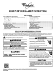
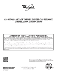
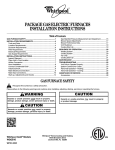
1
INSTALLATION INSTRUCTIONS FOR
SELF-CONTAINED PACKAGE AIR CONDITIONERS
AND HEAT PUMP UNITS
ATTENTION INSTALLATION PERSONNEL
Prior to installation, thoroughly familiarize yourself with this installation manual. Observe all safety warnings.
During installation or repair, caution is to be observed.
It is your responsibility to install the product safely and to educate the customer on its safe use.
Placeholder
for Bar
Code
Whirlpool® Models
WPH43***H, WPH44***H,
WPC43***H, WPC44***H
WPIO-352B
These installation instructions cover the outdoor installation of
self-contained package air conditioner and heating units. See the
Specification Sheets applicable to your model for information
regarding accessories.
NOTE: Please contact your distributor or our website for the
applicable Specification Sheets referred to in this manual.
Tradewinds Distributing Company, LLC
14610 Breakers Drive
Jacksonville, FL 32258
TABLE OF CONTENTS
SAFETY INSTRUCTIONS...............................................................2
MESSAGE TO HOMEOWNER.......................................................3
TO THE INSTALLER.......................................................................3
IMPORTANT NOTE TO THE OWNER REGARDING
PRODUCT WARRANTY.................................................................3
SHIPPING INSPECTION ................................................................3
REPLACEMENT PARTS ................................................................4
CODES AND REGULATIONS ........................................................4
EPA Regulations...........................................................................4
National Codes.............................................................................4
MAJOR COMPONENTS ................................................................4
PREINSTALLATION CHECKS.......................................................4
CLEARANCES AND ACCESSIBILITY...........................................4
Unit Location ................................................................................5
Ground Level Installations—Outside Slab...................................5
Rooftop Installations ....................................................................5
DUCTING.........................................................................................6
Connecting the Return and Supply Flexible Duct
in Manufactured or Modular Housing Application.......................6
Plenum Application ......................................................................6
Filters ............................................................................................7
PIPING .............................................................................................7
Condensate Drain ........................................................................7
Make Electrical Connections .......................................................7
OPERATION....................................................................................9
Start-up Procedure and Checklist—Cool....................................9
Start-up Procedure and Checklist—Heat Pump .........................9
Final System Checks..................................................................10
COMPONENTS.............................................................................10
Contactor....................................................................................10
Crankcase Heater.......................................................................10
Condenser Motor .......................................................................10
Compressor................................................................................10
Contactor Relay..........................................................................10
Defrost Control ...........................................................................10
Outdoor Thermostat...................................................................10
Reversing Valve Coil...................................................................10
Indoor Blower Motor ..................................................................10
Blower Interlock Relay................................................................10
Explanation and Guidance—Heat Pump...................................11
DEFROST CONTROL ...................................................................12
Suggested Field Testing/Troubleshooting.................................12
AIRFLOW MEASUREMENT AND ADJUSTMENT .....................12
Speed Tap Adjustments for Indoor Blower Motor—
PSC Motor..................................................................................12
Speed Tap Adjustments for Indoor Blower Motor—
X-13 Motor..................................................................................12
BLOWER PERFORMANCE DATA...............................................13
ELECTRIC HEAT INSTALLATION AND ADJUSTMENT............15
SYSTEM MAINTENANCE ............................................................16
Service........................................................................................16
TROUBLESHOOTING CHART.....................................................16
WIRING DIAGRAM—WPC43(24-48)AH......................................18
WIRING DIAGRAM—WPC4360AH, WPC44(24-60)AH,
WPC4460AH..................................................................................19
WIRING DIAGRAM—WPC43(24-48)AH......................................20
WIRING DIAGRAM—WPC4360AH, WPC44(24-48)AH..............21
WIRING DIAGRAM—WPH43(24-48)AH......................................22
WIRING DIAGRAM—WPH4360AH, WPH44(24-60)AH..............23
ASSISTANCE OR SERVICE .........................................................24
SAFETY INSTRUCTIONS
The following symbols and labels are used throughout this manual to indicate immediate or potential safety hazards. It is the owner’s
and installer’s responsibility to read and comply with all safety information and instructions accompanying these symbols. Failure to
heed safety information increases the risk of personal injury, property damage and/or product damage.
Recognize this symbol as a safety precaution.
WARNING
WARNING
Do not connect to or use any device that is not designGoodman
36 damage,
certified for use with this
unit. Serious property
personal injury, reduced unit performance and/or hazardous
conditions may result from the use of such non-approved
devices.
Hazards or unsafe
practices1could result in property
Goodman
damage, product damage, severe personal injury or death.
CAUTION
WARNING
HIGH VOLTAGE!
Hazards or unsafe practices may result in property
damage, product damage, personal injury or death.
Disconnect ALL power before servicing.
Goodman
6
Multiple power sources
may be present.
Failure to do so may cause property damage,
personal injury or death.
2
WARNING
Connecting unit ductwork
to unauthorized
Goodman
98 heat producing
devices such as a fireplace insert, stove, etc., may result
in property damage, fire, carbon monoxide poisoning,
explosion, personal injury or death.
WARNING
This product containsGoodman
or produces a45
chemical or
chemicals which may cause serious illness or death and
which are known to the State of California to cause
cancer, birth defects or other reproductive harm.
WARNING
To avoid property damage, personal injury or death, do
not use this furnace if any part of the furnace has been
under water. Immediately call a qualified service technician
to inspect the furnace and to replace any part of the
control system and any gas control having been under
Goodman 81
water.
WARNING
This unit must not be used as a “construction heater”
during the finishing phases of construction on a new
Goodman 79
structure. This type of use may result in premature failure
of the unit due to extremely low return air temperatures
and exposure to corrosive or very dirty atmospheres.
WARNING
To prevent the risk of property damage, personal injury, or
Goodman 37
death, do not store combustible materials or use gasoline
or other flammable liquids or vapors in the vicinity of this
unit.
WARNING
Installation and repair
of this unit should
Goodman
7
be performed ONLY by individuals meeting
the requirements of an “Entry Level Technician,”
at a minimum, as specified by the Air-Conditioning,
Heating and Refrigeration Institute (AHRI). Attempting
to install or repair this unit without such background may
result in product damage, personal injury or death.
MESSAGE TO HOMEOWNER
These instructions are addressed primarily to the installer;
however, useful maintenance information is included and should
be kept after installation for future reference.
Before using this manual, check the serial plate for proper model
identification.
The installation and servicing of this equipment must be
performed by qualified, experienced technicians only.
TO THE INSTALLER
Carefully read all instructions for the installation prior to installing
unit. Make sure each step or procedure is understood and any
special considerations are taken into account before starting
installation. Assemble all tools, hardware and supplies needed to
complete the installation. Some items may need to be purchased
locally.
After deciding where to install unit, closely look over the
location—both the inside and outside of the home. Note any
potential obstacles or problems that might be encountered as
noted in this manual. Choose a more suitable location if
necessary.
IMPORTANT NOTE TO THE
OWNER REGARDING
PRODUCT WARRANTY
Your warranty certificate is supplied as a separate document with
the unit installed by your contractor. Read the limited warranty
certificate carefully to determine what is and is not covered. Keep
the warranty certificate in a safe place. If you are unable to locate
the warranty certificate, please contact your installing contractor,
or contact customer service at 1-866-944-7575 to obtain a copy.
To receive the 10-Year Parts Limited Warranty, online registration
must be completed within 60 days of installation. Online
registration is not required in California or Quebec.
Full warranty details and instructions are available at
www.whirlpoolhvac.com.
To register your unit, go to www.whirlpoolhvac.com. Click on the
manufacturer’s Comfort CommitmentTM Warranty link located at
the bottom center of the home page. Next, click on the Click
Here to Register Your Product link located at the top center of the
page, and complete the forms in the manner indicated.
SHIPPING INSPECTION
Upon receiving the unit, inspect it for damage from shipment.
Claims for damage, either shipping or concealed, should be filed
immediately with the shipping company. Check the unit model
number, specifications, electrical characteristics and accessories
to determine if they are correct. In the event an incorrect unit is
shipped, it must be returned to the supplier and must not be
installed. The manufacturer assumes no responsibility for
installation of incorrectly shipped units.
3
REPLACEMENT PARTS
MAJOR COMPONENTS
When reporting shortages or damages, or ordering repair parts,
give the complete product model and serial numbers as stamped
on the unit’s nameplate. Replacement parts for this product are
available through your contractor or local distributor. For the
location of your nearest distributor, consult the white business
pages, the yellow page section of the local telephone book or
contact:
Tradewinds Distributing Company, LLC
14610 Breakers Drive
Jacksonville, Florida 32258
1-866-944-7575
The unit includes a hermetically sealed refrigerating system
(consisting of a compressor, condenser coil, evaporator coil with
flowrator), an indoor blower, a condenser fan and all necessary
internal electrical wiring. The heat pump also includes a reversing
valve, solenoid, defrost thermostat and control and loss of charge
protection. The system is factory-evacuated, charged and
performance tested. Refrigerant amount and type are indicated
on rating plate.
CODES AND REGULATIONS
The WPC/WPH AH-series air conditioners and heat pumps are
designed for outdoor use only. This series is available in cooling
capacities of 2, 2¹⁄₂, 3, 3¹⁄₂, 4 and 5 nominal tons of cooling.
Optional field-installed heat kits are available in 5, 8, 10, 15 and
20 kW. The units can be easily installed in manufactured or
modular homes with existing high-static ductwork. The units can
also be easily converted to accommodate a plenum for normal or
low-static applications.
The WPC/WPH AH-series are self-contained packaged units so
the only connections needed for installation are the supply and
return ducts, the line and low voltage wiring and drain
connection. The units are ETL listed and AHRI certified.
The information on the rating plate is in compliance with the FTC
and DOE rating for single-phase units. The 3-phase units in this
series are not covered under the DOE certified program. The
efficiency ratings of these units are a product of thermal
efficiency determined under continuous operating conditions
independent of any installed system.
EPA Regulations
IMPORTANT: The United States environmental protection
agency (EPA) has issued various regulations regarding the
introduction and disposal of refrigerants in this unit. Failure to
follow these regulations may harm the environment and can lead
to the imposition of substantial fines. Because regulations may
vary due to passage of new laws, we suggest a certified
technician perform any work done on this unit. Should you have
any questions, please contact the local office of the EPA.
National Codes
This product is designed and manufactured to permit installation
in accordance with National Codes. It is the installer’s
responsibility to install the product in accordance with National
Codes and/or prevailing local codes and regulations.
4
PREINSTALLATION CHECKS
Before attempting any installation, the following points should be
considered:
■ Structural strength of supporting members
■ Clearances and provision for servicing
■ Power supply and wiring
■ Air duct connections
■ Drain facilities and connections
■ Location may be on any 4 sides of a home, manufactured or
modular, to minimize noise.
CLEARANCES AND
ACCESSIBILITY
The unit is designed to be located outside the building with
unobstructed condenser air inlet and discharge. Additionally, the
unit must be situated to permit access for service and installation.
Condenser air enters from 3 sides. Air discharges upward from the
top of the unit. Refrigerant gauge connections are made on the
right side of the unit as you face the compressor compartment.
Electrical connections can be made either on the right, bottom or
duct panel side of the unit. The best and most common
application is for the unit to be located 10" (25.4 cm) from the wall
(4" [10.2 cm] minimum) with the connection side facing the wall.
Close to the wall application minimizes exposed wiring.
Close to the wall application assures free, unobstructed air to the
other 2 sides. In more confined application spaces, such as
corners, provide a minimum 10" (25.4 cm) clearance on all air
inlet sides. Allow 18" (45.7 cm) minimum for service access to the
compressor compartment and controls. The top of the unit
should be completely unobstructed. If units are to be located
under an overhang, there should be a minimum of 36" (91.4 cm)
clearance and provisions made to deflect the warm discharge air
out from the overhang.
Unit Location
Rooftop Installations
Consider the affect of outdoor fan noise on conditioned space
and any adjacent occupied space. It is recommended that the
unit be placed so that the condenser air discharge does not blow
toward windows less than 25 ft (7.6 m) away. Consideration
should also be given to shade and unit appearance.
The unit should be set on a solid, level foundation—preferably a
concrete slab at least 4" (10.2 cm) thick. The slab should be
above ground level and surrounded by a graveled area for good
drainage. Any slab used as a unit’s foundation should not adjoin
the building as it is possible that sound and vibration may be
transmitted to the structure. For rooftop installation, steel or
treated wood beams should be used as unit support for load
distribution.
Heat pumps require special location consideration in areas of
heavy snow accumulation and/or areas with prolonged
continuous subfreezing temperatures. Heat pump unit bases
have holes under the outdoor coil to permit drainage of defrost
water accumulation. The unit must be situated to permit free
unobstructed drainage of the defrost water and ice. A minimum
2" (5 cm) clearance under the outdoor coil is required in milder
climates.
■
■
■
■
Rooftop Installation
36"
(91.4 cm)
A
Ground Level Installations—Outside Slab
■
■
■
■
Before locating the unit on the roof, check that the roof has
sufficient structural strength to carry the weight of the unit(s)
and snow or water loads as required by local codes. See
specification sheet for weight of units. This is very important
and the installer’s responsibility.
Make proper consideration for the weather-tight integrity of
the roof and proper drainage of condensate.
To ensure proper condensate drainage, the unit must be
installed in a level position.
Consideration should also be given to shade, appearance
and noise.
B
The unit must be mounted on a solid, level foundation.
Select a location that will minimize the length of the supply
and return ducts.
Select a location where external water drainage cannot
collect around the unit.
Consideration should also be given to shade, appearance
and noise.
24"
(61 cm)
D
C
Ground Level Installation
36"
(91.4 cm)
10"
(25.4 cm)
36"
(91.4 cm)
A. Unit
B. Plenum
■
A
■
B
36"
(91.4 cm)
C. Platform
D. Curb
The unit may be installed directly on wood floors or on Class
A, Class B, or Class C roof covering material.
To avoid possible personal injury, a safe, flat surface for
service personnel should be provided.
C
36"
(91.4 cm)
A. Wall
B. Unit
C. Curb
5
DUCTING
WARNING
Connecting unit ductwork
to unauthorized
heat producing
Goodman
98
devices such as a fireplace insert, stove, etc., may result
in property damage, fire, carbon monoxide poisoning,
explosion, personal injury or death.
Ducting work should be fabricated by the installing contractor in
accordance with local codes. Industry manuals may be used as a
guide when sizing and designing the duct system, such as
NESCA (National Environmental Systems Contractors
Association, 1501 Wilson Blvd., Arlington, Virginia 22209).
The unit should be placed as close as possible to the space to be
air conditioned allowing clearance dimensions as indicated.
Ducts should run as directly as possible to supply and return
outlets. Use of nonflammable weatherproof flexible connectors
on both supply and return connections at the unit to reduce noise
transmission is recommended.
It is preferable to install the unit on the roof of the structure if the
registers or diffusers are located in the wall or ceiling. A slab
installation is recommended when the registers are low on the
wall or in the floor.
Connecting the Return and Supply Flexible Duct in
Manufactured or Modular Housing Application
The return and supply fittings are to be attached at the unit to a
suitable square-to-round duct converter. Your distributor has a
factory-designed square-to-round converter transition. The
model numbers of these kits are as follows: Small Chassis 25"
SQRPCH101, Medium Chassis 27.5" SQRPCH102, Large and
Extra Large Chassis 32.5" and 36" SQRPCH103. See
Specification Sheets for dimension details. The SQRPCH101 has
14" (35.6 cm) duct collar on supply and 16" (40.6 cm) duct collar
(equivalent diameter, opening is oval) on the return.
The SQRPCH102 and SQRPCH103 have 14" (35.6 cm) duct
collar on supply and 18" (45.7 cm) duct collar (equivalent
diameter, opening is oval) on the return. The collars are to be
slipped into the openings, and the flanges bent around the
converter. The square-to-round converter is attached to the
flanges of the square duct openings.
6
The flexible duct is then clamped on to the collars. Once the duct
is affixed to the unit, seal the collars and flanges with a proper
waterproof sealant.
It is strongly encouraged to use appropriately-sized ducts based
upon the CFM for your application (unit’s CFM). If duct sizing
through industry manuals or air duct calculators require larger
ducts than converter openings, run larger duct size up to unit
converter openings and reduce with a reducer duct fitting or
transition right at the unit.
Square-to-Round Duct Converter Panel
B
C
A
D
A. Outer flange
B. Square to round duct converter panel
C. Bead
D. Starter flange
Plenum Application
A suitable plenum or square duct must be constructed. The duct
cross-sectional area should be determined by industry duct
sizing manuals or air duct calculators.
On ductwork exposed to outside air conditions of temperature
and humidity, use an insulation with a good K factor, and a vapor
barrier. Industry practices should be followed. Balancing
dampers are recommended for each branch duct in the supply
system. Ductwork should be properly supported from the unit.
NOTE: Proper sealing of all duct work and air handling
compartments is extremely important to overall unit efficiency.
Minimum Filter Size
Filters
Filters are not provided with unit, and must be supplied and
installed in the return duct system by the installer. A field installed
filter grille is recommended for easy and convenient access to
the filters for periodic inspection and cleaning.
Filters must have adequate face area for the rated quantity of the
unit. See the Air Delivery Table for the recommended filter size.
Air Delivery Table
Nominal Filter Area
sq ft (cm2)
7
(6,503)
6
(5,574)
5
(4,645)
4
(3,716)
3
(2,787)
2
(1,858)
Di
500
sa
spo
ble
er
Filt
r
ilte
ent F
an
Perm
1,000 1,500 2,000 2,500
Airflow - SCFM
Nominal Size—in. (cm)
Nominal Area—sq ft (cm2)
10 x 20 (25.4 x 50.8)
1.4 (1,301)
14 x 20 (35.6 x 50.8)
1.9 (1,765)
14 x 25 (35.6 x 63.5)
2.4 (2,230)
15 x 20 (38.1 x 50.8)
2.1 (1,951)
16 x 20 (40.6 x 50.8)
2.2 (2,044)
16 x 25 (40.6 x 63.5)
2.8 (2,601)
20 x 20 (50.8 x 50.8)
2.8 (2,601)
20 x 25 (50.8 x 63.5)
3.5 (3,252)
25 x 25 (63.5 x 63.5)
4.3 (3,995)
3,000 3,500
PIPING
Condensate Drain
Make Electrical Connections
The condensate drain connection of the evaporator is a half
coupling of ³⁄₄" N.P.T. A trap must be installed for proper
condensate drainage.
■ Install the condesate drain trap as shown. Use a ³⁄₄" (1.9 cm)
drain connection size or larger.
■ Do not operate without a trap.
■ Unit must be level or slightly inclined toward drain.
Wiring
WARNING
Goodman 22
To avoid the risk of fire or equipment damage, use
copper conductors.
Condensate Drain
A
F
E
D
A. Drain connection
B. 2" (5.1 cm) minimum
C. 3" (7.6 cm) minimum
B
C
D. Positive liquid seal (required)
E. Flexible tubing—hose or pipe
F. Unit
All wiring should be made in accordance with the National
Electrical Code (N.E.C). The local power company should be
consulted to determine the availability of sufficient power to
operate the unit. The voltage, frequency and phase at the power
supply should be checked to make sure it corresponds to the
unit’s Rated Voltage Requirement.
Install a branch circuit fused disconnect near the unit, in
accordance with the N.E.C. or local codes. Wire sizes and overcurrent protection should be determined from the unit nameplate
ampacity and in accordance with Branch Circuit Ampacity chart
or the N.E.C. Under no circumstances should wiring be sized
smaller than is recommended by either of these 2 sources.
7
Fuses smaller than that recommended on the wiring diagrams
could result in unnecessary fuse failure or service calls. The use
of protective devices of larger size than indicated could result in
extensive damage to the equipment. The manufacturer bears no
responsibility for damage caused to equipment as result of the
use of larger than is recommended size protective devices.
All units have undergone a run test prior to packaging for
shipment. This equipment has been started at minimum rated
voltage and checked for satisfactory operation. Do not attempt to
operate this unit if the voltage is not within the minimum and
maximum voltages shown on nameplate.
All exterior wiring must be within approved weatherproof conduit.
The unit must be permanently grounded in accordance with local
codes, or in absence of local codes, with N.E.C. ANSI/ NFPA No.
70-1984 or latest edition by using ground lug in the control box.
Fuses or HACR-type circuit breakers may be used where codes
permit.
NOTE: Some single-phase units are equipped with a single-pole
contactor. Caution must be exercised when servicing as only
1 leg of the power supply is broken with the contactor.
To wire the unit, make the following high and low voltage
connections:
WARNING
Goodman 6HIGH VOLTAGE!
Disconnect ALL power before servicing.
Multiple power sources may be present.
Failure to do so may cause property damage,
personal injury or death.
Lead
Thermostat
Red
R (24V)
Green
G (Fan)
Orange
O (Rev. Valve)
White
W1 (Heat, 2nd)*
Brown
W2 (Heat, 3rd)*
Yellow
Y (Cool)
C (Blue)
C (Common
*Optional field installed heat connections
Internal Wiring
A diagram detailing the internal wiring of this unit is located on
the electrical box cover. If any of the original wire supplied with
the appliance must be replaced, the wire gauge and insulation
must be the same as the original wiring.
Transformer is wired for 230 volts on the 208/230 models. See
the wiring diagram for 208-volt wiring.
■ For branch circuit wiring (main power supply to unit
disconnect), the minimum wire size for the length of the run
can be determined from the Branch Circuit Ampacity chart
using the circuit ampacity found on the unit rating plate. From
the unit disconnect to the unit, the smallest wire size
allowable in the Branch Circuit Ampacity chart may be used
for the ampacity, as the disconnect must be in sight of the
unit.
■ Wire size based on 60ºC rated wire insulation and 86ºF (30ºC)
ambient temperature.
■ For more than 3 conductors in a raceway or cable, see the
N.E.C. for derating the ampacity of each conductor.
Branch Circuit Ampacity
Low Voltage Wiring
■
Air Conditioners—Connect 24V wires from the thermostat to
the corresponding wires in the control box using 18 AWG as
follows:
Lead
Thermostat
Red
R (24V)
Green
G (Fan)
Yellow
Y (Cool)
White
W1 (Heat)*
Brown
W2 (Heat)*
*Optional field installed heat connections
■ Heat Pumps—Connect 24V wires from the thermostat to the
corresponding wires in the control box using 18 AWG as
follows:
Supply Wire
Length—ft (m)
15
20
25
30
35
40
45
50
200 (61)
6
4
4
4
3
3
2
2
150 (45.7)
8
6
6
4
4
4
3
3
100 (30.5)
10
8
8
6
6
6
4
4
50 (15.2)
14
12
10
10
8
8
6
6
Voltage Wiring
For Internal Wiring, See Wiring Label Attached To Unit
Low Voltage Connectors
T1
T2
L1
Contactor
Y GRW
L2
High Voltage
Disconnect
Switch
High Voltage Power Wiring
24-Volt Control Wiring
Fan
Common
Heat
Single Phase—2 leads should be connected to terminals L1 and
L2 in the electrical control section, using wire sizes specified in
the wiring table.
Cool
High Voltage Wiring
R
W
GY
Thermostat Subbase
8
OPERATION
The reversing valve is energized when the thermostat is
placed in the cooling position.
■ A clicking sound should be noticeable from the reversing
valve.
■ By lowering the temperature setting to call for cooling, the
contactor is energized.
■ The compressor, blower and fan should then be running.
2. After the cooling mode is checked out, turn the thermostat
system switch to “OFF.”
3. Turn the thermostat switch to “HEAT” and the fan switch to
“AUTO.”
4. Slowly raise the heating temperature setting. When the
heating 1st stage makes contact, stop raising the temperature
setting. The compressor, blower and fan should now be
running with the reversing valve in the de-energized (heating)
position.
5. After giving the unit time to settle out, make sure that the unit
is supplying heated air.
6. If the outdoor ambient is above 80°F (26.7ºC), the unit may
trip on its high pressure cutout when on heating. The
compressor should stop.
IMPORTANT: The heating cycle must be thoroughly checked, so
postpone the test to another day when conditions are more
suitable. Do not fail to test the unit.
7. If the outdoor ambient is low and the unit operates properly
on the heating cycle, you may check the pressure cutout
operation by blocking off the indoor return air until the unit
trips.
8. If the unit operates properly in the heating cycle, raise the
temperature setting until the heating 2nd stage makes contact.
Supplemental resistance heat, if installed, should now turn
on. Make sure that the supplemental resistant heat operates
properly.
NOTE: If outdoor thermostats are installed, the outdoor
ambient temperature must be below the set point of these
thermostats for the heaters to operate. It may be necessary
to jumper these thermostats to check heater operation if
outdoor ambient temperature is mild.
9. For thermostats with an emergency heat switch, return to
Step 4.
NOTE: The emergency heat switch is located at the bottom
of the thermostat. Move the switch to emergency heat. The
heat pump will stop, the blower will continue to run, all
heaters will come on and the thermostat emergency heat light
will turn on. All 3-phase models are single-stage heat only.
10. If you are checking the unit in the wintertime when the
outdoor coil is cold enough to activate the defrost control,
observe at least one defrost cycle to make sure the unit
defrosts completely.
■
Start-up Procedure and Checklist—Cool
WARNING
Goodman
HIGH6
VOLTAGE!
Disconnect ALL power before servicing.
Multiple power sources may be present.
Failure to do so may cause property damage,
personal injury or death.
1. Disconnect power at all disconnects.
2. Turn the thermostat system switch to “COOL” and the fan
switch to “AUTO.”
3. Turn the temperature setting to the highest setting.
4. Inspect all of the registers and set them to the normal open
position.
5. Turn on the electrical supply at the disconnect.
6. Turn the fan switch to the “ON” position. The blower should
operate after a 7-second delay.
7. Turn the fan switch to the “AUTO” position. The blower
should stop after a 65-second delay.
8. Slowly lower the cooling temperature until the unit starts. The
compressor, blower and fan should now be operating.
9. Allow the unit to run for 10 minutes. Make sure that cool air is
being supplied by the unit.
10. Turn the temperature setting to the highest position, stopping
the unit. The indoor blower will continue to run for
65 seconds.
11. Turn the thermostat system switch to “OFF” and disconnect
all power when servicing the unit.
Start-up Procedure and Checklist—Heat Pump
WARNING
Goodman
HIGH6
VOLTAGE!
Disconnect ALL power before servicing.
Multiple power sources may be present.
Failure to do so may cause property damage,
personal injury or death.
1. Check that the cooling mode for the heat pump is working
properly according to the procedure listed in the “Start-up
Procedure and Checklist—Cooling Cycle” section.
9
Final System Checks
1. Check to see if all supply and return air grilles are adjusted
and the air distribution system is balanced for the best
compromise between heating and cooling.
2. Check for air leaks in the ductwork. See “Airflow
Measurement and Adjustment” and “Checking Charge.”
3. Make sure that the unit is free of “rattles,” and the tubing in
the unit is free from excessive vibration.
4. Make sure that the tubes and lines are not rubbing against
each other or against the sheet metal surfaces or edges. If
contact is found, correct the trouble.
5. Set the thermostat at the appropriate setting for cooling and
heating or automatic changeover for normal use.
6. Check that the owner is instructed on the unit operation, filter,
servicing, correct thermostat operation, etc.
7. The previous sections are recommended to serve as an
indication that the unit will operate normally.
COMPONENTS
Contactor
Outdoor Thermostat
This control is activated (closed) by the room thermostat for both
heating and cooling. The contactor has a 24-volt coil and
supplies power to the compressor and outdoor fan motor.
These optional controls are used to prevent full electric heater
operation at varying outdoor ambient (0°F to 45°F [-18ºC to 7ºC]).
They are normally open above their set points and closed below
to permit staging of the indoor supplement heater operation. If
the outdoor ambient temperature is below 0° F (-18°C) with 50%
or higher relative humidity (RH), an outdoor thermostat (OT) must
be installed and set at (0°) on the dial. Failure to comply with this
requirement may result in damage to the product which may not
be covered by the manufacturer’s warranty.
Crankcase Heater
This item is “ON” whenever power is supplied to the unit. It
warms the compressor crankcase thereby preventing liquid
migration and subsequent compressor damage. The insert type
heater is self-regulating. It is connected electrically to the
contactor L1 and L2 terminals.
Condenser Motor
This item is activated by the contactor during heating and
cooling, except during defrost and emergency heat operation.
Compressor
This item is activated by the contactor for heating and cooling,
except during emergency heat. It is protected by an internal
overload.
Contactor Relay
This control is activated by the thermostat (24-volt coil) and
supplies power to the contactor.
Defrost Control
The Defrost control provides time/temperature initiation and
termination of the defrost cycle. When a defrost cycle is initiated,
the defrost control shifts the reversing valve to Cooling mode,
stops the outdoor fan and brings on supplemental heat.
Normally, a defrost cycle will take only 2 to 3 minutes unless the
system is low on charge or outdoor conditions are severe (windy
and cold).
10
Reversing Valve Coil
This coil is activated by the thermostat in the cooling mode and
during defrost. It positions the reversing valve pilot valve for
cooling operation.
Indoor Blower Motor
This is activated by setting the room thermostat to COOLING/
HEATING or FAN ON position. The motor is energized through
the EBTDR for PSC motors.
The X-13 motors are activated by setting the room thermostat to
COOLING/HEATING or FAN ON position. The motor is energized
by a 24-volt control signal (from thermostat Y, G or W). X-13
motors are constant torque motors with very low power
consumption. See “Airflow Measurement and Adjustment” for
speed adjustment instructions.
Blower Interlock Relay
This relay is used to energize the blower during the electric heat
operation. Some room thermostats do not energize the motor
during electric heat. This relay ensures blower operation when
the room thermostat energizes heat. This relay has a 240-volt coil
and an 8-amp contact relay. This relay is energized by the electric
heat kit sequencer.
Explanation and Guidance—Heat Pump
When the heat pump is in the cooling cycle, the heat pump
operates exactly as an air conditioning unit.
The heat pump operates in the heating cycle by redirecting
refrigerant flow through the refrigerant circuit external to the
compressor. This is accomplished through the reversing valve.
Hot discharge vapor from the compressor is directed to the
indoor coil (evaporator on the cooling cycle) where the heat is
removed, and the vapor condenses to a liquid. It then goes
through the expansion device to the outdoor coil (condenser on
the cooling cycle) where the liquid is evaporated, and the vapor
goes to the compressor.
When the solenoid valve coil is operated either from heating to
cooling or cooling to heating, the piston in the reversing valve
moves to the low pressure (high pressure) reverse position.
The following illustrations show schematics of a heat pump on
the cooling cycle and the heating cycle. In addition to a reversing
valve, a heat pump is equipped with an expansion device and
check valve for the indoor coil, and similar equipment for the
outdoor coil. It is also provided with a defrost control system.
Cooling Cycle
C
D
B
A
E
F
C
G
H
H
C
I
J
A. Evaporator
B. Service valves
C. Service ports
D. Reversing valve
J
B
E. Condenser
F. Accumulator
G. Compressor
H. Distributors
K
I. Expansion device
J. Indoor coil
K. Check-valve orifices
L. Outdoor coil
Heating Cycle
C
D
B
A
E
F
G
H
H
C
I
J
A. Condenser
B. Service valves
C. Service ports
D. Reversing valve
J
B
E. Evaporator
F. Accumulator
G. Compressor
H. Distributors
K
I. Indoor coil
J. Check-valve orifices
K. Outdoor coil
The expansion devices are flowrator distributors and perform the
same function on the heating cycle as on the cooling cycle.
The flowrator distributors also act as check valves to allow for the
reverse of refrigerant flow.
When the heat pump is on the heating cycle, the outdoor coil is
functioning as an evaporator. The temperature of the refrigerant
in the outdoor coil must be below the temperature of the outdoor
air in order to extract heat from the air. Thus, the greater the
difference in the outdoor temperature and the outdoor coil
temperature, the greater the heating capacity of the heat pump.
This phenomenon is a characteristic of a heat pump. It is a good
practice to provide supplementary heat for all heat pump
installations in areas where the temperature drops below 45°F
(7ºC). It is also a good practice to provide sufficient
supplementary heat to handle the entire heating requirement
should there be a component failure of the heat pump, such as a
compressor, refrigerant leak, etc.
Since the temperature of the refrigerant in the outdoor coil on the
heating cycle is generally below the freezing point, frost forms on
the surfaces of the outdoor coil under certain weather conditions.
Therefore, it is necessary to reverse the flow of the refrigerant to
provide hot gas in the outdoor coil to melt the frost accumulation.
This is accomplished by reversing the heat pump to the cooling
cycle. At the same time, the outdoor fan stops to hasten the
temperature rise of the outdoor coil and lessen the time required
for defrosting. The indoor blower continues to run, and the
supplementary heaters are energized.
11
DEFROST CONTROL
During operation, the power to the circuit board is controlled by a
temperature sensor, which is clamped to a feeder tube entering
the outdoor coil. Defrost timing periods of 30, 60 and 90 minutes
may be selected by connecting the circuit board jumper to 30,
60 and 90 respectively. Accumulation of time for the timing
period selected starts when the sensor closes (approximately
34°F [5ºC]), and when the wall thermostat calls for heat. At the
end of the timing period, the unit’s defrost cycle will be initiated
provided the sensor remains closed. When the sensor opens
(approximately 60°F [16ºC]), the defrost cycle is terminated and
the timing period is reset. If the defrost cycle is not terminated
due to the sensor temperature, a 10-minute override interrupts
the unit’s defrost period.
Circuit Board
DF2
TEST
Jumper Wire
90 A
60
30
DF1
C
Y
W2
R
R DFT
Suggested Field Testing/Troubleshooting
1. Run the unit in the heating mode (room thermostat calling for
heat).
2. Check the unit for proper charge.
NOTE: Bands of frost on the condenser coil indicate low
refrigerant charge.
3. Turn off power to the unit.
4. Disconnect the outdoor fan by removing the purple lead from
“DF2” on the defrost control.
5. Restart the unit and allow frost to accumulate.
6. After a few minutes of operation, the defrost thermostat
should close. To verify this, check for 24 volts between “DFT”
and “C” on the control board. If the temperature at the
thermostat is less than 28°F (-2ºC) and the thermostat is
open, replace the defrost thermostat, since it is defective.
7. When the unit’s defrost thermostat has closed, short the test
pins on the circuit board until the reversing valve shifts,
indicating defrost. This should take up to 21 seconds
depending on what timing period the control is set.
NOTE: After defrost initiation, the short must instantly be
removed, or the unit’s defrost period will last only 2.3 seconds.
8. After the unit’s defrost thermostat has terminated, check the
defrost thermostat for 24 volts between “DFT” and “C.” The
reading should indicate 0 volts (open sensor).
9. Turn off power to the unit.
10. Replace the outdoor fan motor lead to terminal “DF2” on the
circuit board and turn on power.
AIRFLOW MEASUREMENT AND ADJUSTMENT
After reviewing the “Ducting” section, proceed with the airflow
measurements and adjustments. The unit blower curves (see
Specification Sheets) are based on the external static pressure
(ESP per in./W.C.). The duct openings on the unit are considered
internal static pressure. As long as ESP is maintained, the unit will
deliver the proper air up to the maximum static pressure listed for
the CFM required by the application (for example, home,
building, etc.).
In general, 400 CFM per ton of cooling capacity is a rule of
thumb. Some applications depending on the sensible and latent
capacity requirements may need only 350 CFM or up to 425 CFM
per ton. Check condition space load requirements (from load
calculations) and equipment expanded ratings data to match
CFM and capacity.
After the unit is set and the ductwork completed, verify the ESP
with a 1" (2.5 cm) inclined manometer with pitot tubes or a
Magnahelic gauge and confirm CFM to blower curves in the
Specification Sheets. All units have 3-speed blower motors. If the
low speed is not utilized, the speed tap can be changed to
medium or high speed.
NOTE: Never run CFM below 350 CFM per ton. Evaporator
freezing or poor unit performance is possible.
12
Speed Tap Adjustments for Indoor Blower Motor—
PSC Motor
Adjust the CFM by changing the speed tap of the indoor blower
motor at the EBTDR “COM” connection with one of the speed
taps on “M1” or “M2” (Black—High Speed, Blue—Medium
Speed, Red—Low Speed).
Speed Tap Adjustments for Indoor Blower Motor—
X-13 Motor
The blower motor speed for the X-13 motor is controlled by 3 24-volt low-voltage leads: green, yellow and white. The green
lead sets the speed for fan-only mode. The yellow lead sets the
speed for cooling and heat pump heating mode (if applicable).
The white lead sets the speed for electric heat mode (emergency
heat and 2nd stage heat, if applicable).
The leads are factory connected as follows: Green to T1, yellow
to T2 and white to T3. T1 is the low speed setting and is
dedicated to fan-only mode. T2 is medium speed cooling, and
T3 is medium speed heating. T4 is high speed cooling, and T5 is
high speed heating. To adjust the blower speed, move the yellow
and/or white wires to T4 and T5.
NOTE: If more than 1 lead is energized at the same time, the
motor will use the higher speed setting.
See CFM vs. ESP tables in this manual.
BLOWER PERFORMANCE DATA
E.S.P. (In. of H2O)
Model
Speed
Volts—230
0.1
0.2
0.3
0.4
0.5
0.6
0.7
0.8
WPC4324AH
WPH4324AH
Low
CFM
680
640
590
555
505
440
340
-
Watts
155
150
145
140
130
120
110
-
CFM
895
855
815
755
700
630
545
390
Watts
230
220
215
205
195
180
170
145
CFM
1,185
1,130
1,070
1,010
930
850
760
650
Watts
350
340
325
310
295
280
265
245
CFM
1,150
1,080
1,025
975
925
845
-
-
Watts
340
330
315
305
295
280
-
-
CFM
1,335
1,275
1,205
1,135
1,075
985
910
845
Watts
425
415
400
385
370
350
330
310
CFM
1,435
1,355
1,290
1,210
1,130
1,040
960
885
Watts
485
465
455
435
415
400
385
370
CFM
1,180
1,125
1,075
1,020
955
875
655
-
Watts
335
325
315
305
295
275
240
-
CFM
1,350
1,280
1,205
1,130
1,050
985
910
845
Watts
435
420
405
385
375
350
330
310
CFM
1,450
1,370
1,290
1,205
1,130
1,040
960
885
Watts
495
480
465
440
425
400
385
370
CFM
1,425
1,410
1,355
1,310
1,245
1,170
1,080
-
Watts
450
445
430
420
405
390
370
-
CFM
1,620
1,595
1,545
1,485
1,425
1,345
1,250
1,160
Watts
550
540
525
510
495
475
450
425
CFM
1,945
1,935
1,875
1,800
1,730
1,635
1,535
1,440
Watts
765
755
735
715
695
670
640
615
CFM
1,425
1,410
1,355
1,310
1,245
1,170
1,080
-
Watts
450
445
430
420
405
390
370
-
CFM
1,720
1,660
1,585
1,520
1,460
1,365
1,270
-
Watts
560
555
540
530
520
490
470
-
CFM
2,110
2,060
1,980
1,895
1,795
1,705
1,590
1,500
Watts
785
780
765
745
720
705
665
625
Med
High
WPC4330AH
WPH4330AH
Low
Med
High
WPC4336AH
WPH4336AH
Low
Med
High
WPC4342AH
WPH4342AH
Low
Med
High
WPC4348AH
WPH4348AH
Low
Med
High
13
E.S.P. (In. of H2O)
Model
Speed
Volts—230
0.1
0.2
0.3
0.4
0.5
0.6
0.7
0.8
WPC4360AH
WPH4360AH
T1
CFM
1,775
1,635
1,645
1,515
1,510
1,450
1,430
1,400
Watts
395
420
435
445
455
465
470
475
CFM
1,845
1,790
1,715
1,685
1,590
1,580
1,530
1,500
Watts
490
505
520
535
550
560
570
575
CFM
2,025
1,900
1,840
1,780
1,725
1,650
1,620
1,580
Watts
575
595
620
630
645
655
660
670
CFM
934
759
755
638
581
489
-
-
Watts
95
77
76
73
83
90
-
-
CFM
990
837
801
744
696
652
601
-
Watts
107
94
105
110
119
133
142
-
CFM
1,061
989
947
925
876
-
-
-
Watts
126
134
146
158
169
-
-
-
CFM
1,022
929
894
829
797
748
695
643
Watts
116
114
126
134
144
156
168
173
CFM
1,103
1,063
1,012
962
937
-
-
-
Watts
142
154
165
173
185
-
-
-
CFM
1,285
1,240
1,202
1,163
1,124
1,076
1,046
1,003
Watts
205
218
231
244
257
268
280
288
CFM
1,234
1,111
1,071
1,024
933
922
-
-
Watts
144
140
152
164
179
183
-
-
CFM
1,287
1,232
1,186
1,133
1,099
1,053
-
-
Watts
162
175
187
201
213
221
-
-
CFM
1,381
1,325
1,277
1,233
1,181
1,144
-
-
Watts
195
203
217
233
247
258
-
-
CFM
1,272
1,197
1,145
1,106
1,055
998
947
906
Watts
160
168
183
191
211
220
230
243
CFM
1,357
1,297
1,244
1,194
1,147
1,099
1,049
1,008
Watts
188
202
213
228
245
255
267
284
CFM
1,537
1,478
1,431
1,386
1,336
1,293
1,253
1,208
Watts
244
258
274
288
303
317
329
341
T2/T3
T4/T5
WPC4424AH
WPH4424AH
T1
T2/T3
T4/T5
WPC4430AH
WPH4430AH
T1
T2/T3
T4/T5
WPC4436AH
WPH4436AH
T1
T2/T3
T4/T5
WPC4442AH
WPH4442AH
T1
T2/T3
T4/T5
14
E.S.P. (In. of H2O)
Model
Speed
Volts—230
0.1
0.2
0.3
0.4
0.5
0.6
0.7
0.8
WPC4448AH
WPH4448AH
T1
CFM
1,418
1,383
1,349
1,312
1,275
1,228
1,178
1,141
Watts
242
258
273
282
299
308
320
338
CFM
1,175
1,635
1,645
1,515
1,510
1,450
1,430
1,400
Watts
395
420
435
445
455
465
470
475
CFM
1,845
1,790
1,715
1,685
1,590
1,580
1,530
1,500
Watts
490
505
520
535
550
560
570
575
CFM
1,775
1,635
1,645
1,515
1,510
1,450
1,430
1,400
Watts
395
420
435
445
455
465
470
475
CFM
2,025
1,900
1,840
1,780
1,725
1,650
1,620
1,580
Watts
575
595
620
630
645
655
660
670
T2/T3
T4/T5
WPC4460AH
WPH4460AH
T1/T2/T3
T4/T5
NOTES:
■ Data shown is dry coil. Wet coil pressure drop is approximate.
■ 0.1" H2O for 2-row indoor coil; 0.2" H2O for 3-row indoor coil;
0.3" H2O for 4-row indoor coil.
■
■
Data shown does not include filter pressure drop,
approximately 0.08" H2O.
Reduce airflow by 2% for 208V operation.
ELECTRIC HEAT INSTALLATION AND ADJUSTMENT
This series of electric cooling and heat pump package equipment
is designed to accept a field installed electric heat kit. The unit is
equipped to easily install the HKR Series Electric Heat Kit. Full
installation instructions are included in this kit. Please use this
document for guidance in field equipping the package unit with
electric heat.
Choose the heat kit that fits the application for the specific
installation. Permanently mark the unit’s nameplate with the
model being installed. High and low voltage connections are
detailed in the heat kit instructions.
Indoor Blower motor speed tap selection may need to be
modified to accommodate normal continuous operation to
prevent a nuisance trip. See the following charts.
WPC/WPH43(24-60) Models
Electric Heat KW
Unit Model Number
5
8
10
15
20
WPC/WPH4324H41**
M(F)
M(F)
M(F)
H
NA
WPC/WPH4330H41**
L(F)
L(F)
L(F)
M
NA
WPC/WPH4336H41**
M(F)
M(F)
M(F)
H
NA
WPC/WPH4342H41**
L(F)
L(F)
M
M
H
WPC/WPH4348H41**
M(F)
M(F)
M(F)
M(F)
H
WPC/WPH4360H41**
2(F)
2(F)
2(F)
2(F)
2(F)
WPC/WPH44(24-60)
Models
Electric Heat KW
Unit Model Number
5
8
10
15
20
WPC/WPH4424H41**
T3
T3
T3
T5
NA
WPC/WPH4430H41**
T3
T3
T3
T5
NA
WPC/WPH4436H41**
T3
T3
T3
T5
NA
WPC/WPH4442H41**
T3
T3
T3
T3
T5
WPC/WPH4448H41**
T3
T3
T3
T3
T3
WPC/WPH4460H41**
T3
T3
T3
T3
T3
T1—Fan Only: T2—Normal Speed Cooling; T3—Normal Speed
heating; T4—High Speed Cooling; T5—High Speed Heating
H/3—High; M/2—Medium; L/1—Low
Speed taps description: H/M/L—PSC: 3/2/1—X-13
15
SYSTEM MAINTENANCE
■
WARNING
HIGH VOLTAGE!
Disconnect ALL power before servicing.
Goodman 6
Multiple power sources may be present.
■
Failure to do so may cause property damage,
personal injury or death.
■
The self-contained package air conditioner and heat pump
should operate for many years without excessive service calls if
the unit is installed properly. However, it is recommended that the
homeowner inspect the unit before a seasonal start-up. The coils
should be free of debris, so adequate airflow is achieved. The
return and supply registers should be free of any obstructions.
The filters should be cleaned or replaced.
These few steps will help to keep the product up time to a
maximum. The Troubleshooting Chart should help in identifying
problems if the unit does not operate properly.
■
Service
NOTE: The following information is for use by qualified service
agency only. Others should not attempt to service this
equipment.
Common Causes of Unsatisfactory Operation of Heat
Pump on the Heating Cycle.
■
Inadequate Air Volume Through Indoor Coil
When a heat pump is in the heating cycle, the indoor coil is
functioning as a condenser. The return air filter must always
be clean, and sufficient air volume must pass through the
indoor coil to prevent excessive discharge pressure, and high
pressure cutout.
Outside Air Into Return Duct
Do not introduce cold outside air into the return duct of a heat
pump installation. Do not allow air entering the indoor coil to
drop below 65°F (18ºC). Air below this temperature will cause
low discharge pressure, thus low suction pressure, and
excessive defrost cycling resulting in low heating output. It
may also cause false defrosting.
Undercharge
An undercharged heat pump on the heating cycle will cause
low discharge pressure resulting in low suction pressure and
frost accumulation on the outdoor coil.
Poor “Terminating” Sensor Contact
The defrost terminating sensor must make good thermal
contact with the outdoor coil tubing. Poor contact may not
terminate the defrost cycle quickly enough to prevent the unit
from cutting out on high discharge pressure.
Malfunctioning Reversing Valve
This may be due to:
1. Solenoid not energized—In order to determine if the
solenoid is energized, touch the nut that holds the
solenoid cover in place with a screwdriver. If the nut
magnetically holds the screwdriver, the solenoid is
energized and the unit is in the cooling cycle.
2. No voltage at the solenoid—Check unit voltage. If no
voltage, check wiring circuit.
3. Valve will not shift—If the unit is undercharged, check for
leaks. If valve body damaged, replace valve. If unit is
properly charged, and it is on the heating cycle, raise the
discharge pressure by restricting airflow through the
indoor coil. If the valve does not shift, tap it lightly on both
ends with a screwdriver handle.
NOTE: Do not tap the valve body.
If the unit is on the cooling cycle, raise the discharge
pressure by restricting airflow through the outdoor coil. If
the valve does not shift after the above attempts, turn off
the unit and wait until the discharge and suction pressure
equalize, and repeat above steps. If the valve does not
shift, replace it.
TROUBLESHOOTING CHART
WARNING
Goodman 6 Long
HIGH VOLTAGE!
Disconnect ALL power before servicing.
Multiple power sources may be present.
Failure to do so may cause property damage, personal injury or death.
Symptom
Possible Cause
High head—low suction
■
Restriction in liquid line or flowrator
■
Remove or replace with proper size flowrator.
High head—high or
normal suction
■
Dirty condenser coil
Overcharged
Condenser fan not running
■
Clean coil.
Correct system charge.
Repair or replace condenser fan.
■
■
16
Remedy
■
■
Symptom
Possible Cause
Low head—high
suction
■
Remedy
Incorrect flowrator
Defective compressor valves
Flowrator not seating properly
■
Power off or loose electrical
connection
Thermostat out of calibration; set
too high
Defective contactor
Blown fuses or tripped circuit
breaker
Transformer defective
High or low pressure control
(optional) open
Compressor overload contacts open
■
■
■
Loose connection
Compressor stuck
Grounded or open winding
Open internal overload
Low voltage connection
Capacitor weak, open or shorted
Low suction—cool
compressor, iced
evaporator coil
■
Low indoor airflow
■
Compressor short
cycles
■
■
■
Unit will not run.
■
■
■
■
■
■
■
Condenser fan runs;
compressor does not
run.
■
■
■
■
■
Registers sweat
■
■
■
■
■
■
■
■
■
■
■
■
■
■
Defective overload protector
Unit cycling on low pressure control
High pressure switch cuts out
■
Low airflow
■
■
■
■
■
High suction pressure
■
■
■
Insufficient cooling
■
■
■
■
Evaporator coil freezing
or frosting
■
■
■
Excessive load
Defective compressor
Reversing valve not seating
properly.
■
Improperly sized unit
Improper airflow
Incorrect refrigerant charge.
Incorrect voltage
■
Low airflow
Low refrigerant charge
Operating unit in cooling mode
below 65ºF (18ºC) outdoor
temperature
■
■
■
■
■
■
■
■
■
Replace with correct flowrator.
Replace compressor.
Check for debris under flowrator or deformed flowrator. Remove
debris or replace flowrator.
Check for unit voltage at contactor in unit.
Reset thermostat.
Check for 24 volts at contactor coil. Replace if contacts are
open.
Replace fuse or reset circuit breaker. Check wiring. Replace
transformer.
Reset high pressure control or check unit charge.
High pressure control opens at 610 psig, and low pressure
control opens at 22 psig.
Replace compressor.
NOTE: Wait at least 2 hours for overload to reset.
Check for unit voltage at compressor.
Check and tighten all connections.
Wait at least 2 hours for overload to reset. If still open, replace
the compressor.
At compressor terminals, voltage must be within 10% of
nameplate volts when unit is operating.
Check capacitor. Replace if defective.
Increase speed of blower or reduce restriction.
Replace air filters.
Replace overload protector. Check for correct voltage.
Check refrigerant charge and/or airflow.
Check airflow (indoor and outdoor).
Increase speed of blower or reduce restriction.
Replace air filters.
Recheck load calculation
Replace compressor.
Replace reversing valve.
Recalculate load.
Check airflow—should be approximately 400 CFM per ton.
Charge per procedure attached to unit service panel.
At compressor terminals, voltage must be within 10% of
nameplate volts when unit is operating.
Check airflow—should be approximately 400 CFM per ton.
Check for dirty air filters and that all duct outlets are open.
Properly charge unit.
Install or check low ambient control—should be open below 65ºF
(18ºC) outdoor temperature.
17
WIRING DIAGRAM—WPC43(24-48)AH
WARNING
Goodman 6 Long
HIGH VOLTAGE!
Disconnect ALL power before servicing.
Multiple power sources may be present.
Failure to do so may cause property damage, personal injury or death.
PR
BK
BK
R
R
G
G
BL
1
2
3
C
2 08
2 40
EBTDR
R
XF M R -R
XF M R -C
C
K1
NO
K1
COM
N O TE # 4
PR
BU
2 4V
BK
PR
BU
R
BK
T2
BU
Speed
Up
M1
See NOTE #6
C
BK
BK
R
R
2
0
8
2
4
0
/
1
/
60
L2
R
L1
T1
R
NC
M2
R
BK
Y
BK
R
GND
PR
PR
R
BU
3
PR
1
2
4
BR
BK
R
Y
BR
LV JB
BK
R
BU
Y
H
C
RCC F
SA
(If Used)
See NOTE 5
PL F
6
9
2
5
8
1
4
7
3
F
R
(T R A N S 2 40V )
PR (M 1) R
BK
BR
(C O M )
BK
EM
3 Speed
PR
BK
PR
BK
BR
BU
W2
C
+
+
R
EM
BR
Y
BR
High
BR
2 Speed
Optional
T
h
e
r
m
o
s
t
a
t
Control
Box
BK
Low
BU
PR
Y
R
G
W1
BR
R
PR
PR
BR
Y
R
G
W
S C R
HPS
R
CM
COM P
FC
R
CH
NO TE #3
FC
L1
Symbol
Factory Wiring
Component Legend
BK
C
Contactor
Line Voltage
Low Voltage
BU
CM
Condenser Motor
Optional High Voltage BR
COMP Compressor
G
DC
Defrost Control
OR
DFT
Defrost Thermostat
Field Wiring
PR
High Voltage
GND
Equipment Ground
Low Voltage
R
HPS
High Pressure Switch
W
HVDR High Voltage Defrost Relay
Y
LPS
Low Pressure Switch
LVDR Low Voltage Defrost Relay
LVJB Low Voltage Junction Box
PLF
Female Plug Connector
RVC
Reversing Valve Coil
RCCF Run Capacitor for Compressor and Fan
SA
Start Assist
TR
Transformer
VSM
Variable Speed Motor
VSTB Variable Speed Terminal Block
L2
Supply Voltage
20 8-24 0/1/60
CH
See N OTE # 3
T2
C
C
COMP
C
H RCCF
F
S
S .A .
1 P
L
3 F
3
4
M1
EBTDR
N
C
2
CM
N O TE # 5
BR
1
C
R
T1
N O T E #2
EBTDR
M2
NO
EM
C OM
FC
208 -24 0
NOTE #4
2
3
TR
24 V
EBTDR
R
C
G
C
HPS
4
P
L 5
6
R
W2
W1
Thermostat
18
Y
G
C
Color
Black
Blue
Brown
Green
Orange
Purple
Red
White
Yellow
NOTES:
Replacement wire must be the same size and type insulation as the original (at least 105ºC). Use copper conductor only.
To change evaporator motor speed, replace the lead on EBTDR "COM" with lead on EBTDR "M1 or "M2."
Crankcase heat not supplied on all units.
For 208-volt transformer operation, move the purple wires from Terminal 3 to Terminal 2 on transformer.
Start Assist factory-equipped, when required.
Use copper conductors only.
++ Use N.E.C. Class 2 wire.
See unit rating plate for the type and sixe of overcurrent protection.
Wiring is subject to change. Always refer to the wiring diagram on the unit for the most up-to-date wiring.
WIRING DIAGRAM—WPC4360AH, WPC44(24-60)AH
WARNING
Goodman 6 Long
HIGH VOLTAGE!
Disconnect ALL power before servicing.
Multiple power sources may be present.
Failure to do so may cause property damage, personal injury or death.
PR
N O TE #3
BK
BK
1
2
3
C
208
240
PR
PR
BU
BK
BU
2 4V
R
2
0
8
2
4
0
/
1
/
60
L2
T2
R
C
BU
BK
BK
See NOTE 5
L1
T1
R
Y
GND
G
BK
R
R
Y
PR
LV JB
Y
R BR
W
BU
Y
H
BU
C
F
R CC F
G
W
G
P LF
3
6
9
2
5
8
1
4
7
BR
PR
Y
R
G
W
Y
R
G
W1
BR
BU
W2
C
++
BR
R
BK
SA
(If Used) See NOTE 4
Control
Box
R
BK
PR
Y
G
W
C L G N
1 2 3 4 5
T
h
e
r
m
o
s
t
a
t
B R BK
Y
S C R
CM
COMP
H PS
W
See NOTE 2
EM
L1
L2
Supply Voltage
208-240/1/60
T2
C
C
R
T1
C
CO M P
C
H RCCF
S
F
S.A.
CM
N O TE # 4
If Used
N O TE #2
L
N
EM
1
G
3
2
20 8- 240
N O TE #4
3
2
1
TR
24 V
1 EM C
2
3
See NOTE #2
4
5
6
P LF
C
H PS
R
W2
W1
Thermostat
Y
G
C
Component Legend
Symbol
C
Contactor
BK
CM
Condenser Motor
BU
COMP Compressor
BR
DC
Defrost Control
G
DFT
Defrost Thermostat
OR
GND
Equipment Ground
PR
HPS
High Pressure Switch
R
HVDR High Voltage Defrost Relay
W
LPS
Low Pressure Switch
Y
LVDR Low Voltage Defrost Relay
LVJB
Low Voltage Junction Box
PLF
Female Plug Connector
RVC
Reversing Valve Coil
RCCF Run Capacitor for Compressor and Fan
SA
Start Assist
TR
Transformer
VSM
Variable Speed Motor
VSTB
Variable Speed Terminal Block
Color
Black
Blue
Brown
Green
Orange
Purple
Red
White
Yellow
Factory Wiring
Field Wiring
High Voltage
Line Voltage
Low Voltage
Low Voltage
Optional High Voltage
NOTES:
Replacement wire must be the same size and type insulation as the original (at least 105ºC). Use copper conductor only.
To change evaporator motor speed, move the white and yellow leads on from "EM2" and "EM3" to "EM4" and "EM5." If
both leads are energized, the higher speed setting is used.
For 208-volt transformer operation, move the purple wires from Terminal 3 to Terminal 2 on transformer.
Start Assist factory-equipped, when required.
Use copper conductors only.
++ Use N.E.C. Class 2 wire.
See unit rating plate for the type and sixe of overcurrent protection.
Wiring is subject to change. Always refer to the wiring diagram on the unit for the most up-to-date wiring.
19
WIRING DIAGRAM—WPC43(24-48)AH
WARNING
Goodman 6 Long
HIGH VOLTAGE!
Disconnect ALL power before servicing.
Multiple power sources may be present.
Failure to do so may cause property damage, personal injury or death.
PR
BK
BK
R
R
G
G
BU
EBTDR
R
XF M R -R
XF M R -C
C
K1
NO
K1
COM
Speed
Up
M1
1
2
3
C
2 08
2 40
N O TE # 4
PR
BU
2 4V
BK
PR
BU
R
BK
T2
2
0
8
2
4
0
/
1
/
60
L2
R
C
BU
BK
BK
R
R
NC
M2
See NOTE #6
L1
T1
R
R
BK
Y
BK
R
GND
PR
PR
BU
PR
R
BR
BK
Y
BR
LV JB
BK
R
BU
Y
H
C
RCC F
SA
(If Used)
See NOTE 5
PL F
6
9
2
5
8
1
4
7
3
F
R
(T R A N S 2 40V )
PR (M 1) R
BK
(C O M )
BK
EM
BR
W2
C
PR
BK
PR
BK
T
h
e
r
m
o
s
t
a
t
R
BK
BR
High
Control
Box
Y
S C R
R
EM
BR
3 Speed
BR
FC
2 Speed
Optional
CM
COM P
R
CH
NO TE #3
FC
L2
L1
Supply Voltage
20 8-24 0/1/60
CH
See N OTE # 3
T2
C
T1
R
C
COMP
C
S .A .
N
C
4
M1
EBTDR
Symbol
BK
BU
BR
G
OR
PR
R
W
Y
1 P
L
3 F
3
2
CM
N O TE # 5
BR
1
Factory Wiring
Line Voltage
Low Voltage
Optional High Voltage
Field Wiring
High Voltage
Low Voltage
C
H RCCF
F
S
N O T E #2
EBTDR
M2
NO
EM
C OM
FC
208 -24 0
NOTE #4
2
3
TR
24 V
EBTDR
R
C
G
C
4
P
L 5
F
6
R
W2
W1
Y
Thermostat
20
BR
BU
+
+
Low
BU
PR
Y
R
G
W1
BR
R
PR
PR
BR
Y
R
G
W
G
C
Color
Black
Blue
Brown
Green
Orange
Purple
Red
White
Yellow
Component Legend
C
Contactor
CM
Condenser Motor
COMP Compressor
DC
Defrost Control
DFT
Defrost Thermostat
GND
Equipment Ground
HVDR High Voltage Defrost Relay
LPS
Low Pressure Switch
LVDR Low Voltage Defrost Relay
LVJB Low Voltage Junction Box
PLF
Female Plug Connector
RVC
Reversing Valve Coil
RCCF Run Capacitor for Compressor and Fan
SA
Start Assist
TR
Transformer
VSM
Variable Speed Motor
VSTB Variable Speed Terminal Block
NOTES:
Replacement wire must be the same size and type insulation as the original (at least 105ºC). Use copper conductor only.
To change evaporator motor speed, replace the lead on EBTDR "COM" with lead on EBTDR "M1 or "M2."
Crankcase heat not supplied on all units.
For 208-volt transformer operation, move the purple wires from Terminal 3 to Terminal 2 on transformer.
Start Assist factory-equipped, when required.
Use copper conductors only.
++ Use N.E.C. Class 2 wire.
See unit rating plate for the type and sixe of overcurrent protection.
Wiring is subject to change. Always refer to the wiring diagram on the unit for the most up-to-date wiring.
WIRING DIAGRAM—WPC4360AH, WPC44(24-48)AH
WARNING
Goodman 6 Long
HIGH VOLTAGE!
Disconnect ALL power before servicing.
Multiple power sources may be present.
Failure to do so may cause property damage, personal injury or death.
PR
N O TE #3
BK
BK
1
2
3
C
208
240
PR
PR
BU
BK
BU
2 4V
R
2
0
8
2
4
0
/
1
/
60
L2
T2
R
C
BU
BK
BK
See NOTE 5
L1
T1
R
Y
GND
G
BK
R
R
Y
PR
LVJB
Y
R BR
W
BU
Y
H
BU
C F
R CC F
G
W
G
P LF
3
6
9
2
5
8
1
4
7
BR
PR
Y
R
G
W
Y
R
G
W1
BR
BU
W2
C
++
BR
R
BK
SA
(If Used) See NOTE 4
Control
Box
R
BK
PR
Y
W
G
T
h
e
r
m
o
s
t
a
t
BR B K
Y
S C R
C L G N
1 2 3 4 5
CM
C O MP
H PS
W
See NOTE 2
EM
L1
L2
Supply Voltage
20 8-24 0 /1/60
T2
C
C
R
T1
C
COMP
C
S
H
RCC F
F
S.A.
CM
NO TE #4
If Used
NO TE #2
L
N
EM
1
G
3
2
20 8-24 0
NO TE #4
3
2
1
TR
24 V
1 EM C
2
3
See NOTE #2
4
5
6
P LF
C
HPS
R
W2
W1
Y
G
C
Component Legend
Symbol Color
C
Contactor
BK
Black
CM
Condenser Motor
BU
Blue
COMP Compressor
BR
Brown
DC
Defrost Control
G
Green
DFT
Defrost Thermostat
OR
Orange
GND
Equipment Ground
PR
Purple
HPS
High Pressure Switch
R
Red
HVDR High Voltage Defrost Relay
W
White
LPS
Low Pressure Switch
Y
Yellow
LVDR
Low Voltage Defrost Relay
LVJB
Low Voltage Junction Box
PLF
Female Plug Connector
RVC
Reversing Valve Coil
RCCF Run Capacitor for Compressor and Fan
SA
Start Assist
TR
Transformer
VSM
Variable Speed Motor
VSTB
Variable Speed Terminal Block
Factory Wiring
Field Wiring
Line Voltage
High Voltage
Low Voltage
Low Voltage
Optional High Voltage
NOTES:
Replacement wire must be the same size and type insulation as the original (at least 105ºC). Use copper conductor only.
To change evaporator motor speed, move the white and yellow leads on from "EM2" and "EM3" to "EM4" and "EM5." If
both leads are energized, the higher speed setting is used.
For 208-volt transformer operation, move the purple wires from Terminal 3 to Terminal 2 on transformer.
Start Assist factory-equipped, when required.
Use copper conductors only.
++ Use N.E.C. Class 2 wire.
See unit rating plate for the type and sixe of overcurrent protection.
Wiring is subject to change. Always refer to the wiring diagram on the unit for the most up-to-date wiring.
Thermostat
21
WIRING DIAGRAM—WPH43(24-48)AH
WARNING
Goodman 6 Long
HIGH VOLTAGE!
Disconnect ALL power before servicing.
Multiple power sources may be present.
Failure to do so may cause property damage, personal injury or death.
PR
BK
BK
R
R
G
G EB TD R
R
X F M R -R
X F M R -C
C
BU
Speed
Up
K1
NO
K1
CO M
N O TE # 4
PR
1
2
3
C
20 8
24 0
BK
BU
24 V
BK
M1
PR
NC
M2
R
T2
L2
T1
L1
C
3
BK
BK
2
R
R
R
1
BU
BU
PR
BU
4
BR
Y
BK
See NOTE #6
OR
R
BK
Y
2
0
8
2
4
0
/
1
/
6
0
OR
BU
G ND
OR
DC
OR
C
Y
PR
R
O
BK
O
LV D R
R
Y
BK
Y
BK
BR
PR
Bushing
W
R
R
R
DF1
DF 2
R
Y
R
H
R
C
RC CF
R
PLF
6
9
2
5
8
1
4
7
3
F
SA
BR
PR
R
R
BU
(C O M ) B K
FC
L1
L2
T2
C
C
COMP
C
C
S
RC C F
H
H VD R
F
S .A .
BR
1
1 P
L
3 F
3
4
M1
N
C
2
CM
NOTE #5
NO T E#2
E B TD R
E B TD R
M2
NO
COM
EM
FC
2 08 -2 4 0
N O TE # 4
2
3
1
TR
24 V
E B T DR
R
R
DF T
DF T
R
C
G
DC
Y
C
W2
RVC
LV D R
O
O
P 4
L
F 5
C
HPS
6
R
W2
O
W1
Thermostat
22
Y
G
RVC
BK
2 Speed
Optional
Control
Box
BK
Y
S C R
LPS
OR
CM
T
h
e
r
m
o
s
t
a
t
COMP
OR
HPS
CH
NOTE # 3
FC
Symbol Color
Component Legend
Factory Wiring
C
Contactor
BK Black
Line Voltage
CM
Condenser Motor
Low Voltage
BU Blue
COMP Compressor
Optional High Voltage BR Brown
DC
Defrost Control
G Green
Field Wiring
DFT
Defrost Thermostat
OR Orange
High Voltage
GND
Equipment Ground
PR Purple
Low Voltage
HPS
High Pressure Switch
R Red
HVDR High Voltage Defrost Relay
W White
LPS
Low Pressure Switch
Y
Yellow
LVDR Low Voltage Defrost Relay
LVJB
Low Voltage Junction Box
PLF
Female Plug Connector
RVC
Reversing Valve Coil
RCCF Run Capacitor for Compressor and Fan
SA
Start Assist
TR
Transformer
VSM
Variable Speed Motor
VSTB
Variable Speed Terminal Block
See NOTE #3
R
T1
EM
BR
BK
PR
BR
High
BR
DF T
3 Speed
BK
Low
BK
EM
Supply Voltage
20 8-2 40 /1 /6 0
CH
++
PR
R
(T R A N S 2 40 V )
PR
(M 1) R
R
BK
BR
Y
R
G
W1
O
W2
C
BR
(If Used)
See NOTE #5
PR
Y
R
G
W
OR
BR
BU
BU
BK
R
H VDR
LV J B
W
LPS
C
NOTES:
Replacement wire must be the same size and type insulation as the original (at least 105ºC). Use copper conductor only.
To change evaporator motor speed, replace the lead on EBTDR "COM" with lead on EBTDR "M1 or "M2."
Crankcase heat not supplied on all units.
For 208-volt transformer operation, move the purple wires from Terminal 3 to Terminal 2 on transformer.
Start Assist factory-equipped, when required.
Use copper conductors only.
++ Use N.E.C. Class 2 wire.
See unit rating plate for the type and sixe of overcurrent protection.
Wiring is subject to change. Always refer to the wiring diagram on the unit for the most up-to-date wiring.
WIRING DIAGRAM—WPH4360AH, WPH44(24-60)AH
WARNING
Goodman 6 Long
HIGH VOLTAGE!
Disconnect ALL power before servicing.
Multiple power sources may be present.
Failure to do so may cause property damage, personal injury or death.
R
PR
R
BU
BU
BU
See NOTE 5
BU
BU
PR
BU
BU
R
SA (If Used)
See NOTE 4
T
h
e
r
m
o
s
t
a
t
PR
Control
Box
PR
See NOTE 2
Supply Voltage
208-240/1/60
Component Legend
Symbol
C
Contactor
BK
CM
Condenser Motor
BU
COMP Compressor
BR
DC
Defrost Control
G
DFT
Defrost Thermostat
OR
GND
Equipment Ground
PR
HPS
High Pressure Switch
R
HVDR High Voltage Defrost Relay
W
LPS
Low Pressure Switch
Y
LVDR
Low Voltage Defrost Relay
LVJB
Low Voltage Junction Box
PLF
Female Plug Connector
RVC
Reversing Valve Coil
RCCF Run Capacitor for Compressor and Fan
SA
Start Assist
TR
Transformer
VSM
Variable Speed Motor
VSTB
Variable Speed Terminal Block
HVDR
(High Volt)
S.A.
If Used
208-240
See NOTE #2
Color
Black
Blue
Brown
Green
Orange
Purple
Red
White
Yellow
Factory Wiring
Line Voltage
Low Voltage
Optional High Voltage
Field Wiring
High Voltage
Low Voltage
NOTES:
Replacement wire must be the same size and type insulation as the original (at least 105ºC). Use copper conductor only.
To change evaporator motor speed, move the white and yellow leads on from "EM2" and "EM3" to "EM4" and "EM5." If
both leads are energized, the higher speed setting is used.
For 208-volt transformer operation, move the purple wires from Terminal 3 to Terminal 2 on transformer.
Start Assist factory-equipped, when required.
Use copper conductors only.
++ Use N.E.C. Class 2 wire.
See unit rating plate for the type and sixe of overcurrent protection.
Wiring is subject to change. Always refer to the wiring diagram on the unit for the most up-to-date wiring.
Thermostat
23
ASSISTANCE OR SERVICE
If you need further assistance, you can write to the below
address with any questions or concerns:
Tradewinds Distributing Company, LLC
14610 Breakers Drive
Jacksonville, FL 32258
WPIO-352B
© 2010. All rights reserved.
Please include a daytime phone number in your correspondence.
Or call toll free: 1-866-944-7575.
®Registered Trademark/TM Trademark of Whirlpool, U.S.A.,
Manufactured under license by Tradewinds Distributing Company, LLC, Jacksonville, Florida.
Warranty provided by manufacturer. All other trademarks are owned by their respective companies.
COMFORT COMMITMENT is a trademark of Tradewinds Distributing Company, LLC.
6/10
Printed in U.S.A.