1
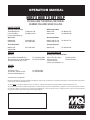
OPERATION MANUAL
NIGHTHAWK SERIES
MODELS LT12D, LT12P
DEDICATED LIGHT TOWER
(DEUTZ F3M1008F DIESEL ENGINE)
(LOMBARDINI LDW 1003 DIESEL ENGINE)
(PERKINS 103-10 DIESEL ENGINE)
Revision #12 (01/20/09)
To find the latest revision of this
publication, visit our website at:
www.multiquip.com
THIS MANUAL MUST ACCOMPANY THE EQUIPMENT AT ALL TIMES.
PN 29543
PROPOSITION 65 WARNING
Diesel engine exhaust and some of
PAGE 2 — LT12 SERIES LIGHT TOWER • OPERATION MANUAL — REV. #12 (01/20/09)
REPORTING SAFETY DEFECTS
If you believe that your vehicle has a defect that could cause a crash or could cause
injury or death, you should immediately inform the National Highway Traffic Safety
Administration (NHTSA) in addition to notifying Multiquip at 1-800-421-1244.
If NHTSA receives similar complaints, it may open an investigation, and if it finds
that a safety defect exists in a group of vehicles, it may order a recall and remedy
campaign. However, NHTSA cannot become involved in individual problems
between you, your dealer, or Multiquip.
To contact NHTSA, you may either call the Vehicle Safety Hotline toll-free at 1-888327-4236 (TTY: 1-800-424-9153), go to http://www.nhtsa.dot.gov; or write to:
Administrator
NHTSA
1200 New Jersey Avenue S.E.
Washington, DC 20590
You can also obtain information about motor vehicle safety from
http://www.safecar.gov.
LT12 SERIES LIGHT TOWER • OPERATION MANUAL — REV. #12 (01/20/09) — PAGE 3
TABLE OF CONTENTS
LT12 Series Light Tower
Proposition 65 Warning ........................................... 2
Reporting Safety Defects......................................... 3
Table Of Contents .................................................... 4
Safety Information .............................................. 5-12
Lamp Footcandle Plot ............................................ 13
Specifications ................................................... 14-15
Dimensions ............................................................ 16
General Information ............................................... 17
Components ..................................................... 18-19
Control Panel .................................................... 20-21
Inspection ......................................................... 22-25
Operation .......................................................... 26-30
Maintenance ..................................................... 31-35
Maintenance — Trailers .................................... 36-37
Troubleshooting ................................................ 38-43
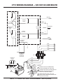
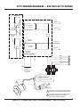
Lt12 Wiring Diagram — S/N 902148 and Below.... 44
Lt12 Wiring Diagram — S/N 902148 and Below.... 45
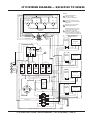
Lt12 Wiring Diagram — S/N 902149 to 902625 .... 46
Lt12 Wiring Diagram — S/N 902149 to 902625 .... 47
Lt12 Wiring Diagram — S/N 902626 and Above ... 48
Lt12 Wiring Diagram — S/N 902626 and Above ... 49
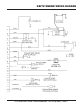
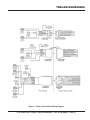
Perkins Engine Wiring Diagram ............................. 50
Deutz Engine Wiring Diagram ............................... 51
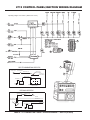
Lt12 Control Panel/Ignition Wiring Diagram ........... 52
Trailer Guidelines .............................................. 53-67
NOTICE
Specifications are subject to change without notice.
PAGE 4 — LT12 SERIES LIGHT TOWER • OPERATION MANUAL — REV. #12 (01/20/09)
SAFETY INFORMATION
Do not operate or service the equipment before reading the
entire manual. Safety precautions should be followed at all
times when operating this equipment. Failure to read and
understand the safety messages and operating instructions
could result in injury to yourself and others.
Potential hazards associated with the operation of this
equipment will be referenced with hazard symbols which
may appear throughout this manual in conjunction with
safety messages.
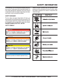
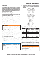
SAFETY MESSAGES
The four safety messages shown below will inform you
about potential hazards that could injure you or others. The
safety messages specifically address the level of exposure
to the operator and are preceded by one of four words:
DANGER, WARNING, CAUTION or NOTICE.
SAFETY SYMBOLS
DANGER
Indicates a hazardous situation which, if not avoided,
WILL result in DEATH or SERIOUS INJURY.
WARNING
Indicates a hazardous situation which, if not avoided,
COULD result in DEATH or SERIOUS INJURY.
CAUTION
Indicates a hazardous situation which, if not avoided,
COULD result in MINOR or MODERATE INJURY.
NOTICE
Addresses practices not related to personal injury.
LT12 SERIES LIGHT TOWER • OPERATION MANUAL — REV. #12 (01/20/09) — PAGE 5
SAFETY INFORMATION
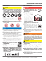
GENERAL SAFETY
CAUTION
NEVER operate this equipment without proper protective
clothing, shatterproof glasses, respiratory protection,
hearing protection, steel-toed boots and other protective
devices required by the job or city and state regulations.
NEVER operate this equipment when not
feeling well due to fatigue, illness or when
under medication.
NEVER operate this equipment under the influence of
drugs or alcohol.
LIGHT TOWER SAFETY
DANGER
NEVER use light tower in rain, snow, or
areas of high humidity that could generate
electrical storms.
The engine of this equipment
requires an adequate free
flow of cooling air. NEVER
operate this equipment in
any enclosed or narrow area
where free flow of the air is
restricted. If the air flow is
restricted it will cause injury
to people and property and
serious damage to the equipment or engine.
NEVER operate the equipment in an
explosive atmosphere or near combustible
materials. An explosion or fire could result
causing severe bodily harm or even
death.
NOTICE
This equipment should only be operated by trained and
qualified personnel 18 years of age and older.
Whenever necessary, replace nameplate, operation and
safety decals when they become difficult read.
Manufacturer does not assume responsibility for any
accident due to equipment modifications. Unauthorized
equipment modification will void all warranties.
NEVER use accessories or attachments that are not
recommended by Multiquip for this equipment. Damage
to the equipment and/or injury to user may result.
The engine fuel exhaust gases contain poisonous carbon
monoxide. This gas is colorless and odorless, and can
cause death if inhaled.
WARNING
NEVER disconnect any emergency or safety devices.
These devices are intended for operator safety.
Disconnection of these devices can cause severe injury,
bodily harm or even death. Disconnection of any of these
devices will void all warranties.
CAUTION
ALWAYS know the location of the nearest
fire extinguisher.
NEVER lubricate components or attempt service on a
running machine.
ALWAYS know the location of the nearest
first aid kit.
ALWAYS ensure light tower is on level ground before use
so that it cannot slide or shift around, endangering workers.
Always keep immediate area free of bystanders.
ALWAYS know the location of the nearest phone or
keep a phone on the job site. Also, know the phone
numbers of the nearest ambulance, doctor and fire
department. This information will be invaluable in the
case of an emergency.
ALWAYS make sure trailer is leveled with all outriggers
extended before raising tower. Outriggers must remain
extended while tower is up.
ALWAYS keep area behind trailer clear of people while
raising and lowering mast.
PAGE 6 — LT12 SERIES LIGHT TOWER • OPERATION MANUAL — REV. #12 (01/20/09)
SAFETY INFORMATION
NEVER remove safety pin or pull mast locking pin while
tower is in a raised position!
LAMP SAFETY
CHECK the mast and winch cables for wear. If any
problem occurs when lower or raising the tower,
STOP immediately! Contact a trained technician for
assistance.
NEVER attempt to replace lamp with the power on.
Always shut down the engine or turn off circuit breakers
when changing the lamp.
NEVER pivot or retract mast while unit is operating.
NEVER use the light tower mast as a crane. DO NOT
lift anything with the mast.
NEVER attach anything to the light tower mast.
ALWAYS lower the light tower when not in use, or if high
winds or electrical storms are expected.
WARNING
ALWAYS allow a sufficient amount of time for the lamp to
cool before touching or changing. The possibility exists of
severe burns.
CAUTION
NEVER use force when installing the lamp. Excessive force
could cause the lamp to break, causing bodily harm.
NOTICE
NOTICE
ALWAYS keep the immediate area surrounding the light
tower clean, neat, and free of debris.
NEVER leave any grease or oil residue on lamp surface
when replacing or removing lamp. This can create hot
spots, reducing the service life of the lamp.
ALWAYS keep the machine in proper running condition.
ALWAYS make sure lamp surface is clean and dry.
Fix damage to machine and replace any broken parts
immediately.
ALWAYS replace with MQ recommended type lamp.
ALWAYS store equipment properly when it is not being
used. Equipment should be stored in a clean, dry location
out of the reach of children and unauthorized personnel.
ALWAYS have a trained technician install and remove
a floodlight, or replace any damaged fixture wiring.
To prevent the light tower from overturning, NEVER use
in winds that exceed 65 mph (105 kph).
LT12 SERIES LIGHT TOWER • OPERATION MANUAL — REV. #12 (01/20/09) — PAGE 7
SAFETY INFORMATION
ENGINE SAFETY
WARNING
DO NOT place hands or fingers inside engine
compartment when engine is running.
NEVER operate the engine with heat shields or
guards removed.
Keep fingers, hands hair and clothing away
from all moving parts to prevent injury.
DO NOT remove the radiator cap while the
engine is hot. High pressure boiling water will gush out
of the radiator and severely scald any persons in the
general area of the generator.
DO NOT remove the coolant drain plug
while the engine is hot. Hot coolant will
gush out of the coolant tank and severely
scald any persons in the general area of
the generator.
DO NOT remove the engine oil drain plug while the
engine is hot. Hot oil will gush out of the oil tank and
severely scald any persons in the general area of the
generator.
CAUTION
NEVER touch the hot exhaust manifold,
muffler or cylinder. Allow these parts to cool
before servicing equipment.
NOTICE
NEVER run engine without an air filter or with a dirty air
filter. Severe engine damage may occur. Service air filter
frequently to prevent engine malfunction.
Wet stacking is a common problem with diesel engines
which are operated for extended periods with light or
no load applied. When a diesel engine operates without
sufficient load (less than 40% of the rated output), it will
not operate at its optimum temperature. This will allow
unburned fuel to accumulate in the exhaust system,
which can foul the fuel injectors, engine valves and
exhaust system, including turbochargers, and reduce
the operating performance.
In order for a diesel engine to operate at peak efficiency,
it must be able to provide fuel and air in the proper ratio
and at a high enough engine temperature for the engine
to completely burn all of the fuel.
Wet stacking does not usually cause any permanent
damage and can be alleviated if additional load is
applied to relieve the condition. It can reduce the system
performance and increase maintenance. Applying an
increasing load over a period of time until the excess
fuel is burned off and the system capacity is reached
usually can repair the condition. This can take several
hours to burn off the accumulated unburned fuel.
State Health Safety Codes and Public Resources
Codes specify that in certain locations, spark arresters
must be used on internal combustion engines that use
hydrocarbon fuels. A spark arrester is a device designed
to prevent accidental discharge of sparks or flames
from the engine exhaust. Spark arresters are qualified
and rated by the United States Forest Service for this
purpose. In order to comply with local laws regarding
spark arresters, consult the engine distributor or the
local Health and Safety Administrator.
NEVER tamper with the factory settings
of the engine or engine governor. Damage
to the engine or equipment can result
if operating in speed ranges above the
maximum allowable.
PAGE 8 — LT12 SERIES LIGHT TOWER • OPERATION MANUAL — REV. #12 (01/20/09)
SAFETY INFORMATION
FUEL SAFETY
DANGER
DO NOT start the engine near spilled fuel or combustible
fluids. Diesel fuel is extremely flammable and its vapors
can cause an explosion if ignited.
ALWAYS refuel in a well-ventilated area, away from
sparks and open flames.
ALWAYS use extreme caution when working with
flammable liquids.
DO NOT fill the fuel tank while the engine is running
or hot.
DO NOT overfill tank, since spilled fuel could ignite if it
comes into contact with hot engine parts or sparks from
the ignition system.
Store fuel in appropriate containers, in well-ventilated
areas and away from sparks and flames.
NEVER use fuel as a cleaning agent.
DO NOT smoke around or near the
equipment. Fire or explosion could result
from fuel vapors or if fuel is spilled on a
hot engine.
TOWING SAFETY
CAUTION
Check with your local county or state safety towing
regulations, in addition to meeting
Department of Transportation (DOT)
Safety Towing Regulations, before towing
your light tower.
In order to reduce the possibility of an accident while
transporting the light tower on public roads, ALWAYS
make sure the trailer that supports the light tower and
the towing vehicle are mechanically sound and in good
operating condition.
ALWAYS inspect the hitch and coupling for wear. NEVER
tow a trailer with defective hitches, couplings, chains, etc.
Check the tire air pressure on both towing vehicle and
trailer. Trailer tires should be inflated to 50 psi cold.
Also check the tire tread wear on both vehicles.
ALWAYS make sure the trailer is equipped with a safety
chain.
ALWAYS properly attach trailer’s safety chains to towing
vehicle.
ALWAYS make sure the vehicle and trailer directional,
backup, brake and trailer lights are connected and
working properly.
DOT Requirements include the following:
• Connect and test electric brake operation.
• Secure portable power cables in cable tray with tie
wraps.
The maximum speed for highway towing is 55 MPH unless
posted otherwise. Recommended off-road towing is not to
exceed 15 MPH or less depending on type of terrain.
Avoid sudden stops and starts. This can cause skidding,
or jack-knifing. Smooth, gradual starts and stops will
improve towing.
Avoid sharp turns to prevent rolling.
Trailer should be adjusted to a level position at all times
when towing.
Raise and lock trailer wheel stand in up position when
towing.
Place chock blocks underneath wheel to prevent rolling
while parked.
Place support blocks underneath the trailer’s bumper
to prevent tipping while parked.
Use the trailer’s swivel jack to adjust the trailer height to
a level position while parked.
ALWAYS shutdown engine before transporting.
Make sure the hitch and coupling of the towing vehicle
are rated equal to, or greater than the trailer “gross
vehicle weight rating.”
LT12 SERIES LIGHT TOWER • OPERATION MANUAL — REV. #12 (01/20/09) — PAGE 9
SAFETY INFORMATION
If lifting through pockets, make sure forks of forklift are
inserted in pockets as far as possible before lifting.
TRANSPORTING SAFETY
CAUTION
Before lifting, make sure that light tower parts are not
damaged and screws are not loosened or lost.
ALWAYS make sure crane or lifting device has been
properly secured to lifting hook of the equipment.
NEVER lift the equipment while engine is running.
Make sure the tower is in the stowed position before
lifting.
STOWED
POSITION
Never allow any person or animal to stand underneath the
equipment while lifting.
DO NOT lift equipment to unnecessary heights.
Loading and Tie-Down on Flatbed Truck
NOTICE
Before loading light tower to flatbed truck, disconnect all
four floodlight connectors and tie-wrap the cables against
the T-bar to prevent damage to the cables and connectors.
CABLE
TIE
Use adequate lifting cable (wire or rope) of sufficient
strength.
Use one point suspension hook and lift straight upwards.
CABLE
CONNECTORS
DISCONNECTED
When loading onto flatbed truck, make sure that front
jackstand of light tower is retracted and in the horizontal
position so that the foot does not make contact with the
deck floor.
FRONT JACKSTAND
RETRACTED
TRANSPORT
TIE-DOWN
POINT (4)
TONGUE
LIFTING BALE
LIGHT TOWER
FORKLIFT
POCKETS
SIDE
JACK
STAND (2)
REAR
JACK
STAND (2)
Make sure that the two side (left and right) and two rear
jackstands are in the vertical postion, slightly extended,
so that each foot makes contact with the deck floor.
Straps and chains should be routed through the transport
tie-down points located beneath each corner of the
cabinet to allow even application of forece to the front
and rear of the machine.
DO NOT secure the unit by running a strap or chain over
the tongue of the light tower. This may cause severe
damage to the unit.
PAGE 10 — LT12 SERIES LIGHT TOWER • OPERATION MANUAL — REV. #12 (01/20/09)
SAFETY INFORMATION
ELECTRICAL SAFETY
DANGER
The electrical voltage required to operate the generator
can cause severe injury or even death through physical
contact with live circuits. Turn generator and all circuit
breakers OFF before performing maintenance on the
generator.
NEVER insert any objects into the output
receptacles during operation. This is
extremely dangerous. The possibility exists
of electrical shock, electrocution or
death.
NEVER operate light tower
or handle any electrical
equipment while standing
in water, while barefoot,
while hands are wet or in the
rain. A dangerous electrical
shock could occur, causing
severe bodily harm or
even death.
ALWAYS make sure the
area above the light tower is
open and clear of overhead
power lines and other
obstructions. The tower
extends in excess of 30
feet (9 meters). Contact
w i t h ove r h e a d p owe r
lines or other obstructions
could result in equipment
damage, electrical shock,
electrocution and even
death.
Similar to boom equipment, light tower may become
energized with high voltage. DO NOT operate the light
tower within a radial distance of 17 feet from high voltage
power lines. If light tower becomes energized with high
voltage, contact with the equipment could result in
electrocution.
Backfeed to a utility system can
cause electrocution and/or property
damage. NEVER connect the
generator to a building’s electrical
system without a transfer switch or
other approved device. All installations
should be performed by a licensed electrician in
accordance with all applicable laws and electrical codes.
Failure to do so could result in electrical shock or burn,
causing serious injury or even death.
Power Cord/Cable Safety
DANGER
NEVER let power cords or cables lay in water.
NEVER use damaged or worn cables or cords when
connecting equipment to generator. Inspect for cuts in
the insulation.
NEVER grab or touch a live power
cord or cable with wet hands. The
possibility exists of electrical shock,
electrocution or death.
Make sure power cables are securely connected.
Incorrect connections may cause electrical shock and
damage to the light tower.
NOTICE
ALWAYS make certain that proper power or extension
cord has been selected for the job.
Grounding Safety
DANGER
The light tower is equipped with a ground terminal for
your protection. ALWAYS complete the grounding path
from the light tower to an extrnal grounding source.
ALWAYS make sure that electrical circuits are properly
grounded to a suitable earth ground (ground rod) per
the National Electrical Code (NEC) and local codes
before operating generator. Severe injury or death by
electrocution can result from operating an ungrounded
generator.
NEVER use gas piping as an electrical ground.
LT12 SERIES LIGHT TOWER • OPERATION MANUAL — REV. #12 (01/20/09) — PAGE 11
SAFETY INFORMATION
BATTERY SAFETY
DANGER
DO NOT drop the battery. There is a possibility that the
battery will explode.
DO NOT expose the battery to open flames,
sparks, cigarettes, etc. The battery contains
combustible gases and liquids. If these
gases and liquids come into contact with a
flame or spark, an explosion could occur.
ENVIRONMENTAL SAFETY
NOTICE
Dispose of hazardous waste properly. Examples of
potentially hazardous waste are used motor oil, fuel
and fuel filters.
DO NOT use food or plastic containers to dispose of
hazardous waste.
DO NOT pour waste, oil or fuel directly onto the ground,
down a drain or into any water source.
WARNING
ALWAYS wear safety glasses when
handling the battery to avoid eye irritation.
The battery contains acids that can cause
injury to the eyes and skin.
Use well-insulated gloves when picking up the battery.
ALWAYS keep the battery charged. If the battery is not
charged, combustible gas will build up.
ALWAYS recharge the battery in a well-ventilated
environment to avoid the risk of a dangerous concentration
of combustible gasses.
If the battery liquid (dilute sulfuric acid) comes into
contact with clothing or skin, rinse skin or clothing
immediately with plenty of water.
If the battery liquid (dilute sulfuric acid) comes into
contact with eyes, rinse eyes immediately with plenty
of water and contact the nearest doctor or hospital to
seek medical attention.
CAUTION
ALWAYS disconnect the NEGATIVE battery terminal
before performing service on the generator.
ALWAYS keep battery cables in good working condition.
Repair or replace all worn cables.
PAGE 12 — LT12 SERIES LIGHT TOWER • OPERATION MANUAL — REV. #12 (01/20/09)
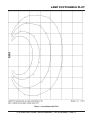
LAMP FOOTCANDLE PLOT
Figure 1. Lamp Footcandle Plot
LT12 SERIES LIGHT TOWER • OPERATION MANUAL — REV. #12 (01/20/09) — PAGE 13
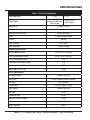
SPECIFICATIONS
Table 1. LT12 Series Specifications
Light Tower Model
Engine Model
Weight (Dry)
Support Points
Wind Stability with Genset.
LT12D
LT12P
Deutz F3M1008F/
Lombardini LDW 1003
Diesel Engine
Perkins 103-10
Diesel Engine
1,550 lbs. (700 kg.)
5
65 mph (80.46 kph)
Lamps
4 1,000-Watt Metal Halide
Lumens
440,000
Light Coverage
Light Termination
5 to 7 acres
4 x 3-pin QD plug
Generator Specifications
GFCI Receptacle Output
120 VAC @ 15 A (US only)
Twist-Lock Receptacle Output
240 VAC @ 25 A (US only)
GFCI Circuit Breaker (Amps)
15 A
Twist-Lock Circuit Breaker (Amps)
25 A
Continuous Output (Watts)
6,000 W
Noise Level @ 23 ft. (7 m)
73 dB
Trailer Specifications
Jackstand Capacity
2,000 lbs. (907 kg.)
Hitch Type
2 in. Ball (Optional Pintle Kit available)
Tire Size
13 in. (330 mm.)
Tire Rim Size
13 x 4.5 in. (330 x 114 mm)
Axle Capacity
2,000 lbs. (907 kg.)
Hub Type
5-Lug
Suspension Type
3-Leaf
Electrical Tail-light Connector
4-Wire
Winch Capacity
Winch Rope Wire
1,500 lbs. (680 kg.)
3/16 in.
PAGE 14 — LT12 SERIES LIGHT TOWER • OPERATION MANUAL — REV. #12 (01/20/09)
SPECIFICATIONS
Table 2. Engine Specifications
Engine Type
Aspirated 4-stroke, 3-cylinder, 1 liter Diesel Engine
Bore X Stroke
2.95 in. X 2.83 in. (75 mm x 72 mm)
Displacement
Max Output Standby
10.5 H.P. at 1,800 R.P.M.
Fuel Tank Capacity
Approx. 30 U.S. Gallons (113 Liters)
Standard Idle Speed
Fuel Type
Lube Oil Capacity
64 Hours
1,800 R.P.M.
N0. 2 Diesel Fuel
4 U.S. Pints (3.78 Liters)
Cooling System
Water-cooled
Coolant Capacity
5 U.S. Pints (4.73 Liters)
Starting Method
Electric Start
Battery Type
Group 24
Total Weight (Dry)
280 lbs. (127 Kg.)
Total Weight (Wet)
287 lbs. (130 Kg.)
Engine Type
3-cylinder, Diesel Engine
Displacement
62.73 cu. in. (1028 cc)
Max Output Standby
12 H.P. at 1,800 R.P.M.
Fuel Tank Capacity
Approx. 30 U.S. Gallons (113 Liters)
Run Time With 4 Lights
Lombardini LDW 1003
Diesel Engine or Deutz
F3M1008F
12 H.P. at 1,800 R.P.M.
Max Output Prime
Run Time With 4 Lights
Perkins 103-10
Diesel Engine
58.21 cu. in. (954 cc)
Standard Idle Speed
Fuel Type
Oil Sump Capacity
64 Hours
1,800 R.P.M.
N0. 2 Diesel Fuel
2.64 U.S. Quarts (2.5 Liters)
Cooling System
Liquid-cooled
Coolant Capacity
5.18 U.S. Quarts (4.9 Liters)
Starting Method
Electric Start
Battery Type
Total Weight (Dry)
Group 24
187.3 lbs. (85 Kg.)
LT12 SERIES LIGHT TOWER • OPERATION MANUAL — REV. #12 (01/20/09) — PAGE 15
DIMENSIONS
DEPLOYED
POSITION
C
STOWED
POSITION
D
E
F
B
A
RIGHT SIDE
G
REAR
Figure 2. Dimensions
Table 3. Dimensions
Reference Letter
Description
Dimension
A
Length (Mast Stowed Position)
170 in. (431 cm.)
B
Length (Mast Deployed Position)
101 in. (256 cm.)
C
Max. Height (Mast Deployed Position)
31.5 ft. (9.6 m)
D
Height (Mast Stowed Position)
74 in. (187 cm.)
E
Ground Clearance (From Axle)
8 in. (20 cm.)
F
Width (Tow Ready)
51 in. (129 cm.)
G
Width (Outriggers Deployed)
109 in. (276 cm.)
PAGE 16 — LT12 SERIES LIGHT TOWER • OPERATION MANUAL — REV. #12 (01/20/09)
GENERAL INFORMATION
The Multiquip LT12 Series Light Tower is a dedicated
general purpose light tower engineered to provide
dependable lighting for a wide range of applications. This
includes lighting for construction sites, industrial locations,
special events, and emergency conditions.
PANEL LIGHT
METAL HALIDE LAMPS
CONVENIENCE RECEPTACLES
The lighting system of the LT12 Series Light Tower is
comprised of 4 metal halide, 1000-watt lamps. These lamps
provide maximum illumination with typical lighting coverage
of 5 to 7 acres. The lamps are controlled by individual circuit
breakers for versatility.
As an added feature, the LT12 is equipped with two
externally mounted auxiliary output receptacles that are
accessible without opening the side panels. The uppermost
receptacle (twist-lock) can provide 240 VAC at 25 amps. The
bottom receptacle is a GFCI receptacle which can supply
120 VAC at 15 amps. These receptacles can be used for
light power tools or other similar applications.
ENGINE
The LT12 Light Tower is powered by a diesel engine that
is equipped with automatic shutdowns for low oil pressure,
high coolant temperature, and alternator charge failure.
STABILITY
A panel light automatically illuminates the control panel and
all functions when the engine access door is opened. This
feature is convenient for night deployment.
FUEL TANK
The 30-gallon fuel tank provides up to 64 hours of run time
while running at 3/4 load.
TRAILER DESIGN
The light tower can be raised vertically in excess of 31.5
feet (9.6 meters) by means of a manual winch. The tower
tensioning system is designed to provide the necessary
tension to safely control the pivot of the tower. The light
tower has a wind stability of up to 65 mph with outriggers
and jackstands fully deployed.
The trailer design of the LT12 light tower withstands the
rigors of the jobsite in addition to providing smooth highway
towing.
LT12 SERIES LIGHT TOWER • OPERATION MANUAL — REV. #12 (01/20/09) — PAGE 17
COMPONENTS
1
4
2
5
7
9
3
6
17
15
14
13 16
8
10
18
12
18
11
Figure 3. Major Components (Control Panel Side)
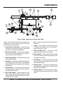
Figures 3 and 4 show the location of the controls and
components for the LT12 series light tower. The function
of each control is described below.
1. Mast Rotation Locking Knob — Unscrew this knob
to release mast for rotation. Tighten this knob to lock
mast after it is set to the desired position.
2. Mast Extension Winch — Use this winch to extend
the mast to the desired height. Maximum height is
approximately 31.5 feet (9.6 meters).
3. Mast Rotation Handles — Grip these handles to rotate
mast to desired position.
4. Lifting Bale — Light tower can be lifted using this lifting
bale. The lifting bale is balanced for a fully configured
light tower. Removal of any components will unbalance
the lifting bale.
5. Forklift Pockets — Light tower can be lifted using
these forklift pockets. Insert the forks of the forklift as
far possible into the pockets.
6. Mast Cradle Support — When towing of the light
tower is required, place the tower mast into the cradle
support. Make sure cradle lock/release pin has been
inserted and mast is locked.
7. T-Bar — Allows the lamps to be mounted vertically or
horizontally.
8. Lamps — Four 1000-watt metal-halide bulbs with
a 110,000 lumens capacity each. Light coverage is
typically between 5 to 7 acres.
9. Cradle Lock/Release Pin — Locks mast in cradle
support and releases mast when removed.
10. Rear Jackstands — There are two jackstands located
at the rear of the trailer. Use these jackstands to level
and support the light tower.
11. Chock Blocks — Place these blocks (not included
as part of the light tower package) under each trailer
wheel to prevent rolling.
12. Outrigger Jacks — Use these 2 outrigger jacks to
level and support the light tower. For more stability, the
outriggers can be deployed.
13. Tongue Jackstand — Use this jackstand to support
the tongue when attaching the light tower to a towing
vehicle.
PAGE 18 — LT12 SERIES LIGHT TOWER • OPERATION MANUAL — REV. #12 (01/20/09)
COMPONENTS
19
24
23
25
20
21
22
REAR
VIEW
FRONT
VIEW
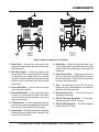
Figure 4. Major Components (Front/Rear)
14. Safety Chain — Always attach safety chain to the
towing vehicle. Never tow the light tower with the safety
chain unattached.
15. Ball Hitch Coupler — Attach this coupler to the
towing vehicle. Use only the specified ball diameter
as indicated on your coupler. Use of any other ball
diameter will create an extremely dangerous condition
which can result in separation of the coupler and ball
or ball failure.
16. Vertical Mast Winch — Use this winch to raise the
mast to the vertical position.
17. Mast Lock/Release Pin — Pull this pin to start placing
the tower mast in the vertical position. When tower
mast has reached full vertical position, insert pin to
keep mast from falling.
18. Tie-Down Points — Used to tie down light tower with
strap or chains to allow even application of force to the
front and rear of the equipment during transport.
20. Brake Lights — Before towing the light tower, make
sure that these lights are operational and are working
correctly. Never tow the light tower if these lights are
inoperative.
21. Engine Exhaust Pipe — Directs engine exhaust to
the rear of the light tower. NEVER block this exhaust
pipe with obstructions. ALWAYS place the generator
in an area free of obstructions.
22. Tires — This light tower uses a ST175-13C size tire.
Replace with only recommended tire size. Never tow
light tower with bad or worn tires.
23. Documentation Box — Contains information
regarding the light tower.
24. 240 VAC Twist-Lock Receptacle — This twist-lock
receptacle provides 240 VAC, 25 amps.
25. 120 VAC GFCI Receptacle — This GFCI receptacle
provides 120 VAC, 15 amps.
19. License Light — This light illuminates the license plate.
Whenever towing of the light tower is required, make
sure this light is operational.
LT12 SERIES LIGHT TOWER • OPERATION MANUAL — REV. #12 (01/20/09) — PAGE 19
CONTROL PANEL
5
4
1
240 VAC/30A
MAIN
BREAKER
240 VAC/30A
MAIN
BREAKER
120 VAC/15A
GFCI
BREAKER
SenDEC
3
120 VAC/15A
GFCI
BREAKER
SenDEC
3
0.0
HOURS
HOURS
5
4
1
1/10
1/10
2
0.0
HOURS
HOURS
1/10
1/10
2
6
6
8
LIGHT CONTROL/BREAKER
* EMERGENCY SHUT DOWNS *
Flashing LED Indicates
Cause of Shut Down
12
WATER TEMP
OIL PRESSURE
9
7
7
PRE-HEAT
INDICATOR
When Light Goes Out
Indicate Start
10
A
ok
AIR FILTER
9
When Flashing
Indicates Low Battery Charge
LOMBARDINI
10
8
OFF O
N
START
13
11
11
PERKINS ENGINE
240 VAC/30A
MAIN
BREAKER
3
5
4
1
LOMBARDINI/DEUTZ ENGINE
120 VAC/15A
GFCI
BREAKER
5
4
1
240 VAC/30A
MAIN
BREAKER
2
120 VAC/15A
GFCI
BREAKER
SenDEC
0.0
HOURS
HOURS
1/10
1/10
2
6
LIGHT CONTROL/BREAKER
12
6
LIGHT CONTROL/BREAKER
8
8
10
12
LOMBARDINI
10
LOMBARDINI
9
13
9
13
7
3
7
11
LOMBARDINI/DEUTZ ENGINE
11
LOMBARDINI ENGINE
= NOT USED
Figure 5. Controls and Indicators
PAGE 20 — LT12 SERIES LIGHT TOWER • OPERATION MANUAL — REV. #12 (01/20/09)
CONTROL PANEL
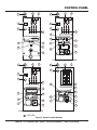
Figure 5 shows the location of the controls and indicators on
the control panel for the different engines used with the LT12
light tower. Service the equipment as needed depending
on the alarm indicated. Below is a brief explanation of each
control or indicator.
1. Internal Cabinet Light Switch — This switch controls
the internal cabinet light for the light tower control
panel. When the cabinet door is raised, the light will
automatically come on. When the cabinet door closes,
the switch is depressed and the light turns off.
2. Internal Cabinet Light — Provides illumination for
the LT12 control panel during nighttime operation.
The light is automatically activated when the cabinet
door is raised.
3. Hour Meter — This digital hour meter indicates the
number of hours machine has been in use.
4. Main Circuit Breaker — A double-pole 25 amp, ON/
OFF circuit breaker which protects the 240 VAC twistlock receptacle from overload. In addition it allows
voltage to be supplied to the GFCI receptacle and 15
amp breakers.
10. PreHeat Indicator — Lights when the
ignition key is turned to the ON position
indicating that the glow plugs are warming
up. When the light goes off, the engine is
ready for starting. If the light is flashing, a
low battery charge is detected (Perkins).
11. Ignition Key Switch — Insert key into
ignition switch and turn clockwise to the ON
position to warm the glow plugs. When preheat indicator light goes OFF, turn the key to
the START position. Release key when
engine starts.
12. Normal Operation Indicator — This
indicator (green lamp) lights when the engine
is functioning normally.
13. Alternator Alarm Indicator — This indicator
lights when the engine has shut down
because the electrical charging system is
not working properly.
5. GFCI Receptacle Circuit Breaker — A single-pole, 15
amp, ON/OFF circuit breaker which protects the GFCI
receptacle from overload.
6. Lamp Circuit Breakers — A single-pole, 15 amp, ON/
OFF circuit breaker for each of the four lamps.
7. Air Filter Alarm Indicator — This indicator
flashes (Perkins) or lights (Lombardini/
Deutz) when a blockage or problem with the
air filter is detected.
8. Water Temperature Alarm Indicator — This indicator
flashes (Perkins) or lights (Lombardini/
Deutz) when the water temperature becomes
too hot for normal engine operation. On
Lombardini/Deutz engines, the unit will shut
down and the indicator light will stay on.
9. Oil Pressure Alarm Indicator — This alarm light
flashes (Perkins) or lights (Lombardini/
Deutz) when the oil pressure has fallen
too low for normal engine operation. On
Lombardini/Deutz engines, the unit will shut
down and the indicator light will stay on
LT12 SERIES LIGHT TOWER • OPERATION MANUAL — REV. #12 (01/20/09) — PAGE 21
OK
INSPECTION
BEFORE STARTING
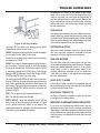
1. Read all safety instructions at the beginning of
manual.
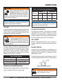
between the two notches as shown in Figure 6. Always
fill with recommended type oil as listed in Tables 4 and
5. See Table 2 for engine oil capacity.
2. Clean the light tower, removing dirt and dust, particularly
the engine cooling air inlet and air cleaner.
3. Check the air filter for dirt and dust. If air filter is dirty,
replace air filter with a new one as required.
4. Check all fastening nuts and bolts for tightness.
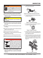
WARNING
Ensure adequate ventilation when
operating the light tower in enclosed areas.
The engine exhaust contains noxious
elements.
Figure 6. Oil Dipstick
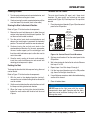
Table 4. Recommended Motor Oil
(Deutz Engines)
°C -40 -35 -30 -25 -20 -15 -10 -5 0 5 10 15 20 25 30 35 40 45 50
°F -40 -31 -22 -13 -4
5 14 23 32 41 50 59 68 77 86 95 104 113 122
SAE 10W
INDOOR INSTALLATION
SAE 20W
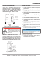
SAE 30
Exhaust gases from diesel engines are extremely
poisonous. Whenever an engine is installed indoors the
exhaust fumes must be vented to the outside. The engine
should be installed at least two feet from any outside wall.
Using an exhaust pipe which is too long or too small can
cause excessive back pressure which will cause the engine
to heat excessively and possibly burn the valves.
Eliminate the danger of deadly carbon monoxide gas.
Remember that exhaust fumes from any gasoline or
diesel engine are very poisonous if discharged in a closed
area. If the light tower is installed indoors, you must make
provisions for venting the engine exhaust to the outside of
the building.
SAE 40
SAE 10W-30
SAE 10W-40
SAE 10W-60
Table 5. Recommended Motor Oil
(Perkins Engines)
°C -40 -35 -30 -25 -20 -15 -10 -5 0 5 10 15 20 25 30 35 40 45 50
°F -40 -31 -22 -13 -4
5 14 23 32 41 50 59 68 77 86 95 104 113 122
SAE 5W-20
SAE 10W-30
SAE 15W-40
SAE 20W-50
ENGINE OIL CHECK
SAE 20
SAE 30
To check the engine oil level, make sure the light tower is
placed on secure level ground with the engine stopped.
1. Remove the filler cap/dipstick from its holder and wipe
it clean.
2. Insert and remove the dipstick from its holder. Check
the oil level shown on the dipstick.
3. If the oil level is low, add oil through the oil filler hole. DO
NOT overfill. Fill to the normal operating level as shown
on the dipstick. Verify that the oil level is maintained
SAE 40
Other types of motor oils may be substituted if they meet
the following requirements:
API Service Classification CH-4
API Service Classification CG-4
API Service Classification CF-4
ACEA Specification E3
ACEA Specification E2
PAGE 22 — LT12 SERIES LIGHT TOWER • OPERATION MANUAL — REV. #12 (01/20/09)
INSPECTION
FUEL CHECK
CAUTION
Diesel fuel and its vapors are dangerous
to your health and the surrounding
environment. Avoid skin contact and/or
inhaling fumes. DO NOT smoke while
refueling. DO NOT attempt to refuel the
light tower if the engine is hot or running.
1. To check the engine fuel level, make sure the light
tower is placed on secure level ground with the engine
stopped.
BATTERY CHECK
WARNING
The operator must wear the appropriate
protective equipment and clothing while
handling the battery.
Failure to wear protective equipment or clothing could
result in serious injury.
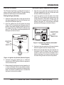
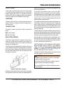
The 12-volt DC battery (Figure 8) is shipped dry and will
require a proper electrolyte level for operation.
2. Lift the light tower access door (Figure 7) opposite the
control panel. Set the door support latch in place to
keep the door open (up).
Figure 8. Battery
When servicing of the battery is required, perform the
following:
A face shield and rubber gloves should be worn while
handling and servicing the battery's electrolyte.
Disconnect battery terminal clamps, and remove the
battery from the generator cabinet when servicing is
required.
DO NOT overfill the battery.
Figure 7. Adding Fuel
3. Remove the fuel cap from the fuel tank.
CAUTION
ALWAYS fill the fuel tank with clean, fresh #2 diesel
fuel. DO NOT fill the fuel tank beyond its capacity. DO
NOT TOP-OFF.
4. Pay attention to the fuel tank capacity when replenishing
fuel. The fuel tank cap must be closed tightly after filling.
Handle fuel in a safe container. If the container does
not have a spout, use a funnel.
WARNING
Electrolyte is an acid and must be
handled with caution. ALWAYS follow
servicing instructions from the electrolyte
manufacturer to ensure safety. Serious
injury can result from careless handling and
noncompliance to safety handling instructions.
Overfilling the battery may cause the electrolyte to
overflow resulting in corrosion to nearby components.
Immediately wash off any spilled electrolyte (battery
acid).
5. Wipe up any spilled fuel immediately!
LT12 SERIES LIGHT TOWER • OPERATION MANUAL — REV. #12 (01/20/09) — PAGE 23
INSPECTION
WARNING
When connecting the positive (+) cable
to the battery's positive (+) terminal post,
DO NOT allow the wrench or any metallic
part to come in contact with the battery's
negative (-) terminal post. This may result in an electrical
short circuit or an explosion.
Table 7. Anti-Freeze Operating Temperatures
Freezing Point
Boiling Point
°C
°F
°C
°F
40
-24
-12
106
222
50
-37
-34
108
226
Vol (%)
Anti-Freeze
NOTICE
Use only distilled water in the battery. Tap water can
reduce the operating life of the battery.
NOTICE
When the antifreeze is mixed with water, the antifreeze
mixing ratio must be less than 50%.
COOLANT
It is recommended that antifreeze/summer coolant be used
with the engine. This can be purchased pre-diluted or in
concentrate and mixed with 50% demineralized water. See
engine owner's manual for more details.
WARNING
If adding coolant/antifreeze mix to the
radiator, DO NOT remove the radiator cap
until the unit has completely cooled. The
possibility of hot coolant exists which can
cause severe burns.
Day-to-day addition of coolant is done from the recovery
tank. When adding coolant to the radiator, DO NOT remove
the radiator cap until the unit has completely cooled.
See Table 6 for engine and radiator, coolant capacities.
Make sure the coolant level in the recovery tank is always
between the "H" and the "L" markings.
Table 6. Coolant Capacity
Engine Type
Coolant Capacity
Perkins 103-10
5 qt. (4.7 liters)
Lombardini LDW 1003
5.18 qt. (4.9 liters)
Deutz F3M1008F
5.18 qt. (4.9 liters)
OPERATION IN FREEZING WEATHER
When operating in freezing weather, make sure the proper
amount of antifreeze (Table 7) has been added.
CLEANING THE RADIATOR
The engine may overheat if the radiator fins become
overloaded with dust or debris. Periodically clean the
radiator fins with compressed air. Cleaning inside the
machine is dangerous, so clean only with the engine turned
off and the negative battery terminal disconnected.
AIR CLEANER
Periodic cleaning/replacement of the air cleaner is
necessary. Inspect it in accordance with the engine owner's
manual.
FAN BELT TENSION
A slack fan belt may contribute to overheating, or to
insufficient charging of the battery. Inspect the fan belt for
damage and wear and adjust it in accordance with the
engine owner's manual.
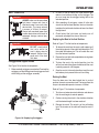
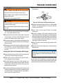
The fan belt tension is proper if the fan belt bends 10 to 15
mm when depressed with the thumb as shown in Figure 9.
Figure 9. Fan Belt Tension
WARNING
Never place hands near the belts or fan
while the engine is running.
PAGE 24 — LT12 SERIES LIGHT TOWER • OPERATION MANUAL — REV. #12 (01/20/09)
INSPECTION
WARNING
The engine's exhaust contains harmful
emissions. ALWAYS ventilate the exhaust
when operating inside tunnels, excavations
or buildings. Direct exhaust away from
nearby personnel.
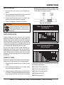
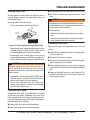
a. Locate the 4 key-lock female 3-pin DIN connectors
on the T-bar. See Figure 10.
KEY-LOCK
FEMALE
CONNECTORS
Before starting the engine, make sure of the following:
The electrical load is disconnected and the main circuit
breaker and all lamp (4) circuit breakers are switched
to the OFF position.
Figure 10. Location of Female Connectors
b. Locate the slot or key (A) on each female connector
as shown in Figure 11.
CAUTION
NEVER start the engine with any circuit breakers in
the ON position.
Light tower is placed on secure level ground with chock
blocks underneath each wheel to prevent the light tower
from rolling.
Outriggers have been fully extended to prevent the trailer
from tipping.
Light tower trailer support stands have been positioned
properly and the trailer is level.
Lamps have been adjusted to desired position.
Chocked blocks have been positioned under each wheel
to prevent trailer from rolling.
Light tower trailer frame has been grounded correctly.
Lamps do not interfere with any overhead obstructions.
DANGER
ALWAYS make sure the area above
light tower is open and clear of
overhead power lines and other
obstructions. The tower extends in
excess of 30 ft. (9 meters). Contact
with overhead power lines or other
obstructions could result in equipment
damage, serious injury or death!
Lamp power cables have been plugged into the
appropriate receptacles (J1-J4) on the T-Bar assembly.
Follow instructions below to correctly install the power
cable plugs.
Figure 11. Female Connector
c. On the corresponding male connector, locate the
key tab (B) as shown in Figure 12.
B
Figure 12. Male Connector
d. Align the key tab (B) on the male connector with
the slot or key (A) on the female connector and
press together until seated.
e. Secure the connector by screwing the knurled
locking nut of the male connector to the threaded
portion of the female connector to ensure
good contact between the two connectors. See
Figure 13.
LOCKING
NUT
J1
J2
J3
J4
Figure 13. Cable Connectors
LT12 SERIES LIGHT TOWER • OPERATION MANUAL — REV. #12 (01/20/09) — PAGE 25
OPERATION
STARTING THE ENGINE
Starting the Engine (Lombardini/Deutz Engines)
The LT12 Series Light Tower is available with two types of
engines (Perkins or Lombardini/Deutz). The engine starting
procedure for both engines are described below.
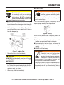
1. Open the access panel door on the right side of the
light tower (opposite the fuel tank). Set the door latch
in place to hold the door open (up).
Starting the Engine (Perkins)
2. Insert the ignition key into the ignition key switch
(Figure 15). Turn the ignition key clockwise one click
to the ON position. The preheat indicator lamp will
light. Wait for this indicator lamp to go OFF. When the
indicator lamp goes OFF, the glow plugs have been
preheated and the engine can now be started.
1. Open the access panel door on the right side of the
light tower (opposite the fuel tank). Set the door latch
in place to hold the door open (up).
2. Insert the ignition key into the ignition key switch
(Figure 14). Turn the ignition key clockwise to the ON
position. The preheat indicator lamp will light. Wait for
this indicator lamp to go OFF. When the indicator lamp
goes OFF, the glow plugs have been preheated and
the engine can now be started.
* EMERGENCY SHUT DOWNS *
Flashing LED Indicates
Cause of Shut Down
WATER TEMP
OIL PRESSURE
IGNITION
KEY
SWITCH
LOMBARDINI
IGNITION
KEY
SWITCH
AIR FILTER
PRE-HEAT
INDICATOR
When Light Goes Out
Indicate Start
When Flashing
Indicates Low Battery Charge
OFF O
N
Figure 15. Ignition Key Switch (Lombardini/
Deutz Engine)
START
3. Continue turning the ignition key all the way clockwise
When the engine has started, release the key.
4. Before placing the light tower into actual operation, let
the engine run for 3-5 minutes. Check any abnormal
sounds or smells that would be associated with a
defective light tower. If any abnormal conditions occur,
shut down the light tower and correct the problem.
Figure 14. Ignition Key Switch (Perkins Engine)
3. Continue turning the ignition key in a clockwise
direction to the START position. When the engine has
started, release the key.
4. Before placing the light tower into actual operation, let
it run for 3-5 minutes. Check for any abnormal sounds
or smells that would be associated with a defective light
tower. If any abnormal conditions occur, shut down the
light tower and correct the problem.
PAGE 26 — LT12 SERIES LIGHT TOWER • OPERATION MANUAL — REV. #12 (01/20/09)
OPERATION
MAST OPERATION
DANGER
ALWAYS make sure the area above
light tower is open and clear of
overhead power lines and other
obstructions. The tower extends
in excess of 30 feet (9 meters).
Contact with overhead power lines
or other obstructions could result in
equipment damage, serious injury
or death!
DANGER
2. As soon as the pin clears the travel position hole,
release it and continue sliding out the outrigger. The
pin must snap into the outrigger locking hole in the
extended position.
3. After extending all outriggers, rotate all trailer jack
stands into the foot down position, then turn the crank
handle on the jackstands clockwise to lower it and level
the light tower.
4. Check behind the light tower and make sure all
personnel and objects are clear of the mast.
Deploying the Mast to Vertical Position
Refer to Figure 17 for the location of components:
DO NOT stand behind
the trailer while the
mast is being raised or
lowered. Serious injury
could result if the mast
falls down.
Outriggers and Support Stands
See Figure 16 for location of components.
1. Make sure both outriggers are extended. To extend the
outriggers, pull the locking pin on the outrigger and hold
while sliding out the outrigger assembly.
1. To release the mast from the mast cradle support, pull
the retaining pin out of the cradle lock/release pin. Pull
the cradle lock/release pin. This will unlock the mast
from the horizontal position.
2. Remove the mast lock/release pin before raising tower
to the vertical position.
3. To place the mast in the vertical position, turn the
vertical mast winch hand lever clockwise until the mast
is pointing upwards at 90 degrees.
4. Once the mast is in the vertical position, insert the mast
lock/release pin to prevent the mast from falling.
Raising the Mast
Once the tower mast has been locked into its vertical
position, the mast can now be raised. The tower allows the
lamps to be extended upwards in excess of 30 feet.
Refer to Figure 17 for location of components.
PULL
OUTRIGGER
TO EXTEND
TO RELEASE
OUTRIGGER
PULL PIN
ROTATE JACK
STAND TO PLACE
IN SUPPORT
POSITION
OUTRIGGER
JACK STAND
1. Turn the mast extension winch clockwise and observe
that the mast begins to extend upwards.
2. Continue turning the winch in the clockwise direction
until the desired height has been reached.
3. Release the winch. This winch is of the self-locking
type. The tension on the cable will keep the mast in
place.
Figure 16. Deploying Outriggers
LT12 SERIES LIGHT TOWER • OPERATION MANUAL — REV. #12 (01/20/09) — PAGE 27
OPERATION
RETAINING
PIN
MAST
CRADLE
SUPPORT
CRADLE
LOCK/
RELEASE
PIN
MAST
EXTENSION
WINCH
VERTICAL
MAST
WINCH
MAST
LOCK/
RELEASE
PIN
MAST
LOCK
HANDLE
MAST
ROTATION
HANDLES
MAST
ROTATION
LOCKING
KNOB
ROTATING THE MAST
Figure 17. Mast Operation
PAGE 28 — LT12 SERIES LIGHT TOWER • OPERATION MANUAL — REV. #12 (01/20/09)
OPERATION
Lowering the Mast
TURNING ON THE LAMPS
1. Turn the mast extension winch counterclockwise, and
observe that the mast begins to lower.
The main circuit breaker (25 amps) and 4 lamp circuit
breakers (10 amps each) are located on the upper
control panel (Figure 18). Each lamp has a 10-amp circuit
breaker.
2. Continue turning the winch counterclockwise until the
mast has been fully retracted (slack in the cable).
Stowing the Mast to Horizontal Position
1. Place the main circuit breaker (Figure 18) on the control
panel to the ON position.
Refer to Figure 17 for the location of components:
MAIN
CIRCUIT
BREAKER
1. Remove the mast lock/release pin to allow the mast
section to be lowered to the horizontal position. Pull
out the mast lock handle to unlatch.
2. Turn the vertical mast winch counterclockwise and
observe that mast begins to approach the horizontal
position. The mast lock handle can now be released.
3. Continue turning the vertical mast winch in the
counterclockwise direction. As the mast approaches
the mast cradle support, pull the retaining pin and
then the cradle lock/release pin to allow the mast to
rest in the cradle.
4. Once the mast is resting in the mast cradle support,
insert the cradle lock/release pin and secure with
retaining pin to keep mast in place.
Rotating the Mast
To change the direction that the lamps are facing, the mast
can be rotated.
Refer to Figure 17 for the location of components.
1. With the mast in the deployed position (vertical),
unscrew the mast rotation locking knob to release the
mast for rotation.
2. Grip the mast rotation handles and rotate the mast until
the lamps are facing the desired direction.
3. When the lamps are facing the desired direction,
tighten the mast rotation lock knob to lock the mast
in place.
240 VAC/30A
MAIN
BREAKER
120 VAC/15A
GFCI
BREAKER
SenDEC
0.0
HOURS
HOURS
1/10
1/10
LIGHT CONTROL/BREAKER
240 VAC/30A
MAIN
BREAKER
GFCI
RECEPTACLE
CIRCUIT
BREAKER
LAMP
CIRCUIT
BREAKERS
120 VAC/15A
GFCI
BREAKER
LIGHT CONTROL/BREAKER
OLD STYLE
NEW STYLE
Figure 18. Control Panel Circuit Breakers
2. Set lamp circuit breaker #1 on the control panel to the
ON position.
3. Wait a few minutes for the ballast to activate. Observe
that lamp #1 is ON.
4. Repeat steps 2 and 3 for lamps 2 through 4.
5. If all the lamp circuit breakers are in the ON position
(up), then all of the lights should be on.
6. If any of the lamps are not on, refer to the troubleshooting
section of this manual.
7. Close all cabinet doors.
NOTICE
NEVER operate the light tower with the engine
compartment doors open. Operation with the doors
open may cause insufficient cooling to the unit, and
damage may result.
LT12 SERIES LIGHT TOWER • OPERATION MANUAL — REV. #12 (01/20/09) — PAGE 29
OPERATION
APPLYING AN EXTERNAL LOAD
NORMAL SHUTDOWN
The light tower is equipped with two auxiliary output
receptacles (Figure 19). The uppermost receptacle (twistlock) located at the front of the light tower can provide
240 VAC at 25 amps. The bottom receptacle is a GFCI
receptacle which can supply 120 VAC at 15 amps.
1. If a load is attached to the generator of the light tower,
remove the load.
2. Set the four lamp circuit breakers on the control panel
to the OFF position.
3. Place the MAIN circuit breaker on the control panel to
the OFF position.
4. Wait a few seconds and observe that all four lamps
are OFF.
5. Let the engine idle for a few minutes with no load.
6. Turn the ignition key to the OFF position. Store key in
a safe location.
7. Lower light tower mast and place in stow position as
outlined in this manual.
8. Place outriggers in tow position, and remove chock
blocks.
Figure 19. Auxiliary Output Receptacles
DANGER
NEVER grab or touch a live power cord
with wet hands. The possibility exists
of electrical shock, electrocution, and
even death!
TESTING THE 120 VAC GFCI RECEPTACLE
Pressing the reset button resets the GFCI receptacle after
being tripped. Pressing the test button (See Figure 20) in
the center of the receptacle will check the GFCI function.
Both receptacles should be tested at least once a month.
9. Store light tower in a clean, dry location out of the reach
of children and unauthorized personnel.
NOTICE
If servicing is required, allow lamps to cool for about
15 minutes before removing lamps.
EMERGENCY SHUTDOWN
1. Turn the ignition key to the OFF position and turn all
circuit breakers to the OFF position.
Figure 20. GFCI Test Button
PAGE 30 — LT12 SERIES LIGHT TOWER • OPERATION MANUAL — REV. #12 (01/20/09)
MAINTENANCE
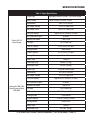
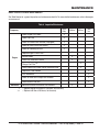
BASIC INSPECTION AND MAINTENANCE
See Table 8 below for a general inspection and maintenance checklist. For more detailed maintenance, refer to the engine
service manual.
Table 8. Inspection/Maintenance
10 hrs
Daily
Frequency
Engine
Generator
Check Engine Fluid Levels
X
Check Fuel Filter
X
Check Air Cleaner Dust Indicator (if equipped)
X
Check for Leaks/Visual Walk Around
X
Check for Loosening of Parts
X
Replace Engine Oil and Filter *
X
Service Battery
X
Clean Unit, Inside and Outside
X
500 hrs
Change Fuel Filter **
X
Clean Radiator and Check Coolant Protection Level
X
1000
hrs
Replace Air Filter Element
X
Test Thermostats
X
Check all Hoses and Clamps/Flush Radiator
X
Clean Inside of Fuel Tank
X
Measure Insulation Resistance Over 3M ohms
*
**
200 hrs
X
— Replace engine oil and filter at 100 hours, first time only.
— Replace fuel filter at 250 hours, first time only.
LT12 SERIES LIGHT TOWER • OPERATION MANUAL — REV. #12 (01/20/09) — PAGE 31
MAINTENANCE
GENERAL INSPECTION
Prior to each use, the light tower should be cleaned and
inspected for deficiencies. Check for loose, missing or
damaged nuts, bolts or other fasteners. Also check for
fuel or oil leaks.
starting becomes impossible. After running out of fuel, or
after disassembling the fuel system, bleed the system.
To restart after running out of fuel, squeeze the fuel primer
bulb to pump fuel into the engine. This unit is equipped with
an automatic air bleeding system.
Air Cleaner
Service Daily
Check dust indicators on control panel daily or every 10
hours of operation. If light is ON, clean the air cleaner
element.
If engine is operating in very dusty and dry grass conditions,
a clogged air cleaner will result in high fuel consumption,
loss of power and excessive carbon buildup in the
combustion chamber.
1. Unlatch the holding clips and take out the air cleaner
element.
2. Clean the inside of the body and cover using a damp
cloth.
3. Blow dry with compressed air (0.69Mpa {7kgf.cm2,
99.4 PSI} maximum) against the side of the element
along the pleats. Then blow dry against outside along
the pleats, then against inside again.
4. Remove one seal each time the element is cleaned.
Cleaning the Fuel Strainer
Clean the fuel strainer if it contains dust or water. Remove
dust or water in the strainer cap and wash it in diesel.
Securely fasten the fuel strainer cap so that fuel will not
leak. Check the fuel strainer every 200 hours of operation
or once a month.
Check Oil Level
5. Replace the outer element (if present, Deutz/
Lombardini engines has a single element only) after
cleaning it 6 times or after one year. Replace the outer
element if indicator is red even after cleaning it.
Check the crankcase oil level prior to each use, or when the
fuel tank is filled. Insufficient oil may cause severe damage
to the engine. Make sure the generator is level. The oil
level must be between the two notches on the dipstick as
shown in Figure 6.
6. If seal washer is damaged or the threads of wing nut
are damaged, replace.
FLUSHING OUT RADIATOR AND CHANGING
COOLANT
7. Remove evacuator valve and clean it with compressed
air. Reinstall.
Fuel Addition
Add diesel fuel (the grade may vary according to season
and locations). Always pour through the mesh filter.
Removing Water from the Tank
After prolonged use, water and other impurities accumulate
in the bottom of the tank. Occasionally remove the drain
cock and drain the contents. During cold weather, the
greater the empty volume inside the tank, the easier it is for
water to condense. This can be reduced by always keeping
the tank as full as possible.
Air Removal
If air enters the fuel injection system of a diesel engine,
WARNING
Allow engine to cool when flushing out
radiator. Flushing the radiator while hot will
damage radiator. In addition, the possibility
of hot coolant exists which can cause
severe burns.
1. Stop the engine and allow to cool. Tighten valve of the
corrosion resistor (if equipped).
2. Turn water filler cap slowly and remove it.
3. Prepare a container to catch the coolant, then open
drain plug of the radiator or heat exchanger and drain
plug of the engine, and drain the coolant.
4. After draining the coolant, close drain plugs and fill
with tap water.
PAGE 32 — LT12 SERIES LIGHT TOWER • OPERATION MANUAL — REV. #12 (01/20/09)
MAINTENANCE
5. When the water level is near the mouth of the water
filler, open drain plugs and start the engine, and run
at low idling. Keep the engine running at low idling and
flush the radiator for about 10 minutes.
6. Adjust the flow of the water flowing in and draining
out to ensure that the radiator is always full during the
flushing operation. While flushing water through the
system, make sure the water inlet hose does not come
out of the radiator filler port.
7. After flushing, stop the engine, open drain plug and
drain the water, then close drain plugs.
8. After draining the water, flush the system with a flushing
agent. See instructions on flushing agent label.
9. After flushing, open drain plugs and drain out all the
water, then close drain plugs and add tap water so the
water level is near the mouth of the water filler.
10. When the water level is near the mouth of the water
filler, open drain plugs and start the engine, run at low
idling and continue to flush the system until clean water
comes out. Adjust the flow of the water flowing in and
draining out to ensure the radiator is always full during
the flushing operation.
11. When clean water comes out, stop the engine, drain
all the water, then close drain plugs.
4. Using a filter wrench, turn filter cartridge to the left
to remove it. If the filter cartridge is filled with a large
amount of oil, wait 10 minutes or so before removing.
Make sure there is no old gasket stuck on the filter
holder.
5. Tighten drain plug. Clean the filter holder, fill the new
filter cartridge with clean engine oil, coat the packing
and thread of the new filter cartridge with engine oil,
then install it to the filter holder. Tighten until the gasket
surface contacts the seal surface of the filter holder,
then tighten it a further 3/4 to 1 turn.
6. Add engine oil through oil filler until the oil level is
between the H and L marks on the dipstick.
7. Run the engine at idling for a short time, then stop the
engine. Recheck the oil level and fill as necessary.
CHECK CABLE WEAR
The wire rope (cable) that raises and extends the mast is
a very important part of the light tower. There is one cable/
hand winch system, located on the tongue of the trailer, that
raises and extends the light tower mast. There is a second
cable/hand winch system located on the mast that serves to
raise and lower the two extendable sections of the mast.
DANGER
13. Supply water until it flows over the water filler.
Wire rope (cable) will fail if it is worn, frayed, misused,
crushed, kinked or damaged in any way. Always check
the cables and pulleys for any abnormalities before
use.
14. Drain the water inside reserve tank, clean the inside of
the reserve tank, then fill with coolant/water mixture to
between the full and low lines.
Do not use it if there is even the slightest cause for
concern and replace any damaged cables or pulleys
immediately.
12. Remove the corrosion resistor (if equipped) and open
valve.
15. Stop the engine, wait for 3 minutes, add tap water until
the water level reaches near the water filler port, then
tighten the radiator cap.
CHANGING OIL
1. Make sure the oil is cool before changing.
2. Set a container directly under the drain plug of the oil
pan. Loosen the drain plug slowly.
3. Check the drained oil for excessive metal particles or
foreign material. Contact the distributor if there is metal
particles or foreign material.
LT12 SERIES LIGHT TOWER • OPERATION MANUAL — REV. #12 (01/20/09) — PAGE 33
MAINTENANCE
REPLACING FUEL FILTER
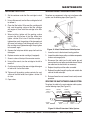
SERVICINGTHE MAST RAISE/LOWER CABLE SYSTEM:
1. Set the container under the filter cartridge to catch
fuel.
To replace any components in the mast raise/lower cable
system, use the following steps (See Figure 21):
2. Using a filter wrench, turn the filter cartridge to the left
to remove it.
3. Clean the filter holder, fill the new filter cartridge with
fuel, coat the packing surface of the filter cartridge
with engine oil, then install the cartridge to the filter
holder.
4. When installing, tighten until the packing surface
contacts the seal surface of the filter holder then
tighten a further 2/3 of a turn. If the filter cartridge is
tightened too much, the packing will be damaged and
will cause fuel leakage. Fuel leakage will occur if the
filter cartridge is not tightened enough. Always tighten
to the correct angle.
5. Squeeze the fuel primer bulb to pump fuel back into
the engine.
6. Replace corrosion resistor cartridge (if equipped).
7. Screw in valves at the top of the corrosion resistor.
Figure 21. Mast Raise/Lower Cable System
1. Lower the mast to the horizontal resting position.
2. Inspect the cable clamps, pulleys, and other components
for worn or damaged parts.
8. Using a filter wrench, turn the cartridge to the left to
remove it.
3. Disconnect the cable from the ball socket pin and
remove from the mast pulley and cable sheave. Detach
the cable from the hand winch as necessary.
9. Coat the seal surface of the new cartridge with engine
oil and install it to the filter holder.
4. Replace the pulley and the cable as needed.
10. Tighten until the packing surface contacts the seal
surface of the filter holder, then tighten a further 2/3
of a turn.
11. Open valves.
5. Rethread the cable through the pulley and reattach the
cable to the ball socket pin.
6. Raise and lower the mast several times to verify correct
operation.
SERVICING THE MAST EXTENSION CABLE SYSTEM:
To replace the cable in the mast extension cable system,
use the following steps (See Figure 22):
CENTER
MAST
PULLEY
UPPER
MAST
LOWER
MAST
PULLEY
CENTER
MAST
LOWER
MAST
SHACKLE
ROUTE TO
HAND WINCH
LOWER
MAST
Figure 22. Mast Extension Cable System
PAGE 34 — LT12 SERIES LIGHT TOWER • OPERATION MANUAL — REV. #12 (01/20/09)
MAINTENANCE
1. Lower the mast to the horizontal resting position.
2. Inspect the cable clamps, pulleys, and other components
for worn or damaged parts. If either of the cables on
the mast needs to be replaced, they should both be
replaced at the same time.
3. Disassemble the mast by disconnecting the cables
from the mast and sliding the sections apart. The lower
cable can be disconnected from the winch.
WARNING
The mast sections are heavy and awkward to handle.
Use proper lifting devices and procedures when
servicing the mast and its components.
4. There are two pulleys in the mast raise/lower cable
system. They should be removed and replaced if worn
or damaged. Worn or damaged pulleys can cause
premature cable failure.
5. Reassemble the mast extension cable system by
connecting the cable to the bottom of the upper mast
and sliding the upper mast into the opening of the
center mast. Connect the second cable to the bottom
of the center mast and slide the center mast into the
opening of the lower mast, observing proper lifting
techniques.
Disconnect the negative terminals of the battery and
cover it, or remove and store it separately.
If the ambient temperature is expected to drop below
0°C, add antifreeze to the radiator.
Cover the light tower and store in a clean, dry place away
from children and unauthorized personnel.
REMOVAL FROM LONG TERM STORAGE
If light tower is going to be used again after long term
storage, perform the following.
Apply oil to the engine valve and rocker arms, and
examine the operating condition of the valves.
Change the oil in engine oil pan.
Replace all the filters.
Flush the inside of the cooling system.
Drain the water from the fuel tank and bleed the air from
the fuel system.
If the engine has not been started for more than one year,
contact your Perkins or Lombardini/Deutz distributor to
have engine overhauled.
6. Route the upper mast cable through the center mast
pulley and connect the free end of the cable to the
lower mast ankle shackle. Route the center mast
cable through the lower mast pulley and connect the
free end of the cable to the hand winch at the bottom
of the lower mast.
7. Raise, extend, retract and lower the mast several times
to verify correct operation.
STORAGE
For storage for over 30 days, the following is required:
Fill the fuel tank completely. Treat with fuel stabilizer if
necessary.
Completely drain oil from the crankcase and refill if
necessary with fresh oil.
Clean the entire light tower.
LT12 SERIES LIGHT TOWER • OPERATION MANUAL — REV. #12 (01/20/09) — PAGE 35
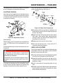
MAINTENANCE — TRAILERS
The following trailer maintenance guidelines are intended
to assist the operator in preventive maintenance.
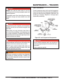
Follow the steps below to disassemble the wheel hub and
service the wheel bearings. See Figure 24.
BEARING
ADJUSTABLE CHANNEL
Your trailer may be equipped with an adjustable channel
(Figure 23) that allows the coupler to be raised or lowered
to a desired height. Periodically check the channel bolts
for damage or loosening.
WHEEL
HUB
OIL
SEAL
BEARING COTTER
PIN
CUP
BEARING
BEARING
CUP
DUST
CAP
LUG
NUT
SPINDLE
WASHER
SPINDLE
NUT
Figure 24. Wheel Hub Components
After removing the dust cap, cotter pin, spindle nut and
spindle washer, remove the hub to inspect the bearings
for wear and damage.
Figure 23. Adjustable Channel
Wheel Bearings
Wheel bearings must be inspected and lubricated once
a year or 12,000 miles to insure safe operation of your
trailer.
If trailer wheel bearings are immersed in water, they must
be replaced.
DANGER
If trailer wheels are under water for a long period of
time, wheel bearings may fail. If this is the case, service
wheel bearings immediately.
Replace bearings that have flat spots on rollers, broken
roller cages, rust or pitting. Always replace bearings
and cups in sets. The inner and outer bearings are to
be replaced at the same time.
Replace seals that have nicks, tears or wear.
Lubricate the bearings with a high quality EP-2
automotive wheel bearing grease.
WHEEL HUB ADJUSTMENT
Every time the wheel hub is removed and the bearings are
reassembled, follow the steps below to check the wheel
bearings for free running and adjust.
Turn the hub slowly, by hand, while tightening the spindle
nut until you can no longer turn the hub by hand.
The possibility exists of the wheels falling off causing
equipment damage and severe bodily harm even
death!
Loosen the spindle nut just until you are able to turn it
(the spindle nut) by hand. Do not turn the hub while the
spindle nut is loose.
If the trailer has not been used for an extended amount
of time, have the bearings inspected and packed more
frequently, at least every six months and prior to use.
Install a new cotter pin through the spindle nut and
axle.
Check the adjustments. Both the hub and the spindle nut
should be able to move freely (the spindle nut motion
will be limited by the cotter pin).
PAGE 36 — LT12 SERIES LIGHT TOWER • OPERATION MANUAL — REV. #12 (01/20/09)
MAINTENANCE — TRAILERS
DANGER
NEVER crawl under the trailer unless it is on firm
and level ground and resting on properly placed and
secured jackstands.
The possibility exists of the trailer falling thus causing
equipment damage and severe bodily harm even
death!
LEAF SUSPENSION
The leaf suspension springs and associated components
(Figure 25) should be visually inspected every 6,000 miles
for signs of excessive wear, elongation of bolt holes, and
loosening of fasteners. Replace all damaged parts
(suspension) immediately.
DANGER
When performing trailer inspection and maintenance
activities, you must jack up the trailer using jacks and
jackstands.
When jacking and using jackstands, place them so
as to clear wiring, brake lines, and suspension parts
(i.e., springs, torsion bars). Place jacks and jackstands
inside of the perimeter strip on the supporting structure
to which the axles are attached.
DANGER
Improper weld repair will lead to early failure of the trailer
structure and can cause serious injury or death.
DO NOT repair cracked or broken welds unless you
have a certified welder perform the repair. If not, have
the welds repaired by your dealer.
Figure 25. Leaf Suspension Components
DANGER
Worn or broken suspension parts can cause loss of
control, damage to equipment and severe bodily injury,
even death!
Check suspension regularly.
WARNING
If the trailer is involved in an accident, have it inspected
immediately by qualified personnel. In addition, the
trailer should be inspected annually for signs of wear
or deformations.
LT12 SERIES LIGHT TOWER • OPERATION MANUAL — REV. #12 (01/20/09) — PAGE 37
TROUBLESHOOTING
Practically all breakdowns can be prevented by proper handling and maintenance inspections, but in the event of a
breakdown, please take remedial action following the diagnosis based on the troubleshooting tables. If the problem cannot
be remedied, please leave the unit as is and consult Multiquip's technical support department or your local dealer.
Symptom
No Voltage Output
Low Voltage Output
High Voltage Output
Circuit Breaker Tripped
Engine fails to start and
starter does not rotate
Engine fails to start and
start rotates
Table 9. Generator Troubleshooting
Solution
Is wiring connection loose?
Check wiring and repair.
Defective Rectifier?
Check and replace.
Is engine speed correct?
Turn engine throttle lever to “High”.
Is wiring connection loose?
Check wiring and repair.
Are wiring connections loose? Check wiring and repair.
Short Circuit in load?
Check load and repair.
Over current?
Confirm load requirements and reduce.
Defective circuit breaker?
Check and replace.
Dead battery?
Replace battery.
Defective ignition switch?
Replace ignition switch.
Defective starter?
Replace starter
Burned fuse?
Replace fuse.
Broken preheat circuit?
Check preheat circuit.
No fuel?
Add diesel fuel.
Defective wiring?
Check wiring.
PAGE 38 — LT12 SERIES LIGHT TOWER • OPERATION MANUAL — REV. #12 (01/20/09)
TROUBLESHOOTING
Table 10. Engine Troubleshooting
Symptom
Engine does not start.
Starter does not run.
Possible Cause
Solution
No fuel?
Replenish fuel.
Air in the fuel system?
Bleed system.
Water in the fuel system?
Remove water from fuel tank.
Fuel pipe clogged?
Clean fuel pipe.
Fuel filter clogged?
Clean or change fuel filter.
Excessively high viscosity of fuel or engine
oil at low temperature?
Use the specified fuel or engine oil.
Fuel with low cetane number?
Use the specified fuel.
Fuel leak due to loose injection pipe
retaining nut?
Tighten nut.
Incorrect injection timing?
Adjust.
Fuel cam shaft worn?
Replace.
Injection nozzle clogged?
Clean injection nozzle.
Injection pump malfunctioning?
Repair or replace.
Seizure of crankshaft, camshaft, piston,
cylinder liner or bearing?
Repair or replace.
Compression leak from cylinder?
Replace head gasket, tighten cylinder head
bolt, glow plug and nozzle holder.
Improper valve timing?
Correct or replace timing gear.
Piston ring and liner worn?
Replace.
Excessive valve clearance?
Adjust.
Battery discharged?
Charge battery.
Starter malfunctioning?
Repair or replace.
Key switch malfunctioning?
Repair or replace.
Wiring disconnected?
Connect wiring.
LT12 SERIES LIGHT TOWER • OPERATION MANUAL — REV. #12 (01/20/09) — PAGE 39
TROUBLESHOOTING
Table 10. Engine Troubleshooting (continued)
Symptom
Engine revolution is not
smooth.
Either white or
blue exhaust gas is
observed.
Either black or dark
gray exhaust gas is
observed.
Deficient output.
Possible Cause
Solution
Fuel filter clogged or dirty?
Clean or change.
Air cleaner clogged?
Clean or change.
Fuel leak due to loose injection pipe
retaining nut?
Tighten nut.
Injection pump malfunctioning?
Repair or replace.
Incorrect nozzle opening pressure?
Adjust.
Injection nozzle stuck or clogged?
Repair or replace.
Fuel over flow pipe clogged?
Clean.
Governor malfunctioning?
Repair.
Excessive engine oil?
Reduce to the specified level.
Piston ring and liner worn or stuck?
Repair or replace.
Incorrect injection timing?
Adjust.
Deficient compression?
Adjust top clearance.
Overload?
Lessen the load.
Low grade fuel used?
Use the specified fuel.
Fuel filter clogged?
Clean or change.
Air cleaner clogged?
Clean or change.
Deficient nozzle injection?
Repair or replace the nozzle.
Incorrect injection timing?
Adjust.
Engine's moving parts seem to be seizing?
Repair or replace.
Uneven fuel injection?
Repair or replace the injection pump.
Deficient nozzle injection?
Repair or replace the nozzle.
Compression leak?
Replace head gasket, tighten cylinder head
bolt, glow plug and nozzle holder.
PAGE 40 — LT12 SERIES LIGHT TOWER • OPERATION MANUAL — REV. #12 (01/20/09)
TROUBLESHOOTING
Table 11. Lamp Troubleshooting
Symptom
Possible Cause
Lamp Burned Out?
Test the lamp in a fixture which is operating properly.
Replace if necessary.
Lamp Loose in Socket?
Inspect lamp base to see if there is arcing at center
contact button. Tighten lamp snugly. Check socket for
damage. Replace if defective.
Lamp Plugs Not Tight?
Check plug and receptacle. Tighten if loose.
Defective Ballast?
Interchange ballast plugs in generator enclosure.
If lamp starts, replace ballast. Check ballast wiring
against diagram. Check for swollen capacitor, charred
wiring, core and coil or other signs of excessive heat.
Low Voltage?
Check line voltage at ballast input. Voltage should
be within 10% of nameplate rating when operating
at normal load. Increase supply voltage or remove
external load.
Improper Ballast?
Proper HID lamps will perform erratically or fail to
start on an improper ballast. The ballast nameplate
data must agree with the line voltage and lamp used.
Improper ballast causes lamp failure. Note: Mercury
lamps of the same wattage will operate properly on
Metal Halide ballasts.
Improper Lamp Operating
Position (Metal Halide only)?
Operating position should agree with the lamp tech.
A BU-HOR lamp can be operated base up vertical to
and including the horizontal and a BD can be operated
base down vertical to, approaching, but not including
the horizontal. A lamp operated beyond the specified
position may not start.
Lamp has been Operating: Cool
Down Time Insufficient?
HID lamps (High Pressure Sodium, Metal Halide,
Mercury Vapor) require from 4 to 8 minutes cool-down
time before restarting. Switch off breaker and allow
lamp to cool.
Improper Ballast?
Improper ballasting can cause flickering or erratic
operation. In the start-up period the lamp may ignite,
start to warm up and then extinguish (cycle).
New Lamp?
Under certain conditions new lamps may "cycle".
Usually after 3 tries to start at 30 to 60 second
intervals, lamps will stabilize and operate satisfactorily.
Defective Lamp?
Replace lamp.
Lamp will not start.
Lamp flickers and goes
out intermittent or
cycling.
Solution
LT12 SERIES LIGHT TOWER • OPERATION MANUAL — REV. #12 (01/20/09) — PAGE 41
TROUBLESHOOTING
Table 11. Lamp Troubleshooting (continued)
Symptom
Possible Cause
Solution
Lamp starts slowly
(ARC does not strike
when switch is first
turned on)
Defective Lamp?
Lamp may glow for extended period of time. Replace after
checking voltage and ballast.
Circuit breaker trips on
lamp start-up
Short Circuit or Ground?
Check wiring against diagram. Check for shorts or ground.
Normal Lamp
Depreciation?
Replace Lamp.
Dirty Lamp or Fixture?
Clean lamp and fixture.
Defective Ballast?
Interchange ballast plugs in generator enclosure. If lamp
returns to normal light output, replace ballast. Check for
swollen capacitor, charred wiring, core and coil, or other signs
of excessive heat.
Wrong Voltage?
Check voltage at ballast input. Voltage should be within 10%
of nameplate rating. Check wiring connections for voltage
loss. Check socket contact point.
Improper Ballast?
Check ballast nameplate against lamp data.
Normal Lamp
Depreciation?
Lamp output and brightness decreases and color changes
slightly as lamps age. Spot replacement with new lamps
may cause noticeable differences in lamp colors. Group
replacement minimizes color differences.
Dirty Fixture?
Dirty fixtures will cause lamps to appear different in color.
Clean fixture.
Wrong Lamp?
Check data on lamps which appear different in color. Replace
with correct color lamp.
Over Voltage from Power
Supply?
Check voltage at ballast. Check for current or voltage surges.
Check for shorted capacitors and replace if defective.
Improper Ballast?
Lamp operated on ballast designed for higher wattage lamp.
Check ballast nameplate against lamp data.
Lamp Damaged?
Check for outer bulb cracks. If air enters outer bulb, arc tube
may continue to burn for 100 hours before failure. Check for
bulb cracks where glass meets the base due to tightening
Lamp too firmly in socket or scoring of glass where socket
inadvertently touches the lamp bulb. Look for broken arc tube
or loose metal parts. Replace lamp. (Bulb leads will cause
oxidation of metal parts.)
Improper Ballast?
Ballast nameplate data should agree with lamp line voltage
and lamp use. If improper ballast is used, the lamp life will be
shortened. A mismatch may also cause the ballast to fail.
Lamp light output low
Lamp colors different.
ARC tube discolored or
swollen.
Short lamp life.
PAGE 42 — LT12 SERIES LIGHT TOWER • OPERATION MANUAL — REV. #12 (01/20/09)
TROUBLESHOOTING
LAMP TROUBLESHOOTING GUIDE
Use the following procedure and wiring diagrams on the
next pages to determine which of the four lamps is not
functioning:
Connections
1. Make sure that lamp #1 power cable is plugged into
the J1 connector on the T-Bar assembly.
2. Make sure that lamp #2 power cable is plugged into
the J2 connector on the T-Bar assembly.
3. Make sure that lamp #3 power cable is plugged into
the J3 connector on the T-Bar assembly.
4. Make sure that lamp #4 power cable is plugged into
the J4 connector on the T-Bar assembly.
Starting
1. Start the generator and verify that there are no
abnormal sounds.
2. Turn CB1 thru CB5 circuit breakers to the ON
position.
3. Wait a few minutes and determine which lamp is not
igniting.
4. If one of the lamps is OFF, disconnect its power cable
and plug it into a receptacle that is known to be working.
DO NOT unplug a power cable from the T-Bar while
power is being supplied by the generator. Always turn
the circuit breaker OFF before unplugging a power
cable.
5. If the lamp still does not ignite after plugging it into a
working receptacle (120 VAC present), then the lamp
is defective and has to be replaced.
6. If the lamp ignites after plugging it into a working
receptacle, continue with step 7.
7. With the voltmeter set to the AC position, connect the
negative lead of the AC voltmeter to any (neutral) white
wire on the junction terminal block. This block connects
all the neutral wires (white) in the system.
8. Connect the positive lead of the voltmeter to the output
side of the circuit breaker where the lamp was originally
OFF and observe that 120 VAC is present. Make sure
circuit breaker is ON.
9. If no output voltage is present, the circuit breaker is
defective and needs to be replaced.
10. If the correct output voltage is present then it can be
assumed that the generator is working correctly and
the correct voltage (120 VAC) is being supplied to the
ballast. Then it can be assumed that the ballast for that
lamp is defective. Replace ballast.
Ballast Removal
1. Remove the power cable from the generator, and make
sure that no voltage is being supplied to the ballast
compartment.
2. Remove the four screws securing the ballast cover,
and remove cover.
3. Make sure to discharge the ballast capacitor.
4. Remove the defective ballast, taking care to guard
against electrical shock when coming in contact with
the ballast and capacitor. The capacitor is known to
store an electrical charge, that when discharged could
result in a harmful shock. Make sure to discharge
capacitor.
LT12 SERIES LIGHT TOWER • OPERATION MANUAL — REV. #12 (01/20/09) — PAGE 43
LT12 WIRING DIAGRAM — S/N 902148 AND BELOW
ROTOR
STATOR
BLACK 1
LINE 1
120 VAC
60 HZ
GREEN 2
ROTOR
WINDINGS
NEUTRAL
240 VAC
60 HZ
FIXED FLOW
CURRENT
DIODE
STATOR
WINDING
JUMPER
WHITE
120 VAC
60 HZ
4
RED 5
LINE 2
EXCITATION
WINDING
BLK
60 HZ 50 HZ
GRN
WHT
RED
4
3
2
1
RED
C1
36µF@425V
EXCITATION
CAPACITOR
TB1
GENERATOR
TERMINAL
BOARD
GRN
RED
BLK
RED
5
1
WHT
4
WHT
U1
W2
GRN
BLK
U2
2 V1
V2
3
CHASSIS
GND
W1
6
B
WHT
C 1 5V
42
F@
N
35µ ITATIO
C
OR
X
E
CIT
A
CAP
BLK
BLK
C1 5V
42
F@
N
18µ ITATIO
R
C
EX ACITO
CAP
C2 5V
42
F@
N
18µ ITATIO
R
EXC ACITO
P
CA
A
35µF
C
NOTES:
SQUARE TYPE 60 Hz GENERATOR
A S/N 902148 AND BELOW, P/N 29643.
B STARTING WITH S/N 902148 AND BELOW
USE ONLY 35µF@425 EXCITATION
CAPACITOR, P/N GECAP35MF.
C SOME UNITS MAY HAVE TWO 18µF
CAPACITORS CONNECTED IN PARALLEL
USE P/N GECAP18MF.
PAGE 44 — LT12 SERIES LIGHT TOWER • OPERATION MANUAL — REV. #12 (01/20/09)
LT12 WIRING DIAGRAM — S/N 902148 AND BELOW
NOTES:
A
J1
J2
BLK
WHT
BLK
BLK
WHT
B 6-WIRE COIL CORD P/N 19955.
J4
J3
BLK
WHT
S/N 902625 AND BELOW
USE ONLY SCREW
TYPE CIRCUIT BREAKERS.
INSTALLED ON UNITS S/N 905512
AND BELOW.
WHT
C WIRE SIZE IS 12 AWG UNLESS
OTHERWISE SPECIFIED.
GRN
T-BAR ASSEMBLY
P/N 19954
D
BLK
BLK 16 AWG
BLK
BLK 16 AWG
B
BLK 16 AWG
BLK
BLK 16 AWG
BLK
WHT 14 AWG
WHT
GRN 16 AWG
SOME UNITS MAY HAVE A 47KW
½ WATT RESISTOR INSTALLED
ACROSS THE CAPACITOR
TERMINALS. OTHER UNITS MAY
HAVE THIS RESISTOR INTERNALLY
INSTALLED WITHIN THE CAPACITOR.
CONTROL PANEL/BALLAST
ASSEMBLY P/N 29614
GRN
6-WIRE COIL CORD
P/N 19955
24µF@480V
CAPACITOR
BALLAST #1
BLK
OUTPUT NEU. 120V IN
RED
BLK
RED
A
CB5
25 AMP
MAIN
BREAKER
YEL
BLK
240 VAC
FROM GENSET
C
BLK
24µF@480V
CAPACITOR
BALLAST #2
OUTPUT NEU. 120V IN
RED
BLK
BLK
4
3
2
1
BLK
BLK
D
YEL
GRN
WHT
CB6
15 AMP
BREAKER
(GFCI)
CB3
10 AMP
BREAKER
(LAMP 3)
CB4
10 AMP
BREAKER
(LAMP 4)
CB2
10 AMP
BREAKER
(LAMP 2)
BLK
CB1
10 AMP
BREAKER
(LAMP 1)
RED
24µF@480V
CAPACITOR
BLK
BALLAST #3
BLK
BLK
OUTPUT NEU. 120V IN
BLK
RED
GND
BLK
BLK
NEU.
LINE
YEL
120 VAC
GFCI
RECEPT.
X
LOAD
W
240 VAC
AUX RECPT.
G
24µF@480V
CAPACITOR
BALLAST #4
GRN
OUTPUT NEU. 120V IN
TB2
RED
Y
RED
NEUTRAL BUS
WHT
YEL
WHT
YEL
WHT
YEL
YEL
BLK
YEL
WHT
CHASSIS
GROUND
GRN
LT12 SERIES LIGHT TOWER • OPERATION MANUAL — REV. #12 (01/20/09) — PAGE 45
LT12 WIRING DIAGRAM — S/N 902149 TO 902625
ROTOR
STATOR
BLACK
4
BLACK
3
BLACK
2
BLACK
1
120 VAC
60 HZ
ROTOR
WINDINGS
240 VAC
60 HZ
FIXED FLOW
CURRENT
DIODE
STATOR
WINDING
120 VAC
60 HZ
EXCITATION
WINDING
BLK
60 HZ 50 HZ
GRN
WHT
RED
4
3
2
1
RED
C1
25µF@425V
EXCITATION
CAPACITOR
111111
22222
44444
33333
TB1
BLK
BLK
BLK
BLK
A
B
RED
RED
C1 5V
42
F@
N
25µ ITATIO
R
EXC ACITO
P
CA
NOTES
STARTING WITH S/N 902149 AND ABOVE
A USE ONLY 60 Hz GENERATOR, P/N 29895.
B STARTING WITH S/N 902149 AND ABOVE
USE ONLY 25µF@425 EXCITATION
CAPACITOR, P/N GECAP25MF.
PAGE 46 — LT12 SERIES LIGHT TOWER • OPERATION MANUAL — REV. #12 (01/20/09)
LT12 WIRING DIAGRAM — S/N 902149 TO 902625
NOTES:
A
J1
J2
BLK
WHT
BLK
BLK
WHT
B 6-WIRE COIL CORD P/N 19955.
J4
J3
BLK
WHT
S/N 902625 AND BELOW
USE ONLY SCREW
TYPE CIRCUIT BREAKERS.
INSTALLED ON UNITS S/N 905512
AND BELOW.
WHT
C WIRE SIZE IS 12 AWG UNLESS
OTHERWISE SPECIFIED.
GRN
T-BAR ASSEMBLY
P/N 19954
D
BLK
BLK 16 AWG
BLK
BLK 16 AWG
B
BLK 16 AWG
BLK
BLK 16 AWG
BLK
WHT 14 AWG
WHT
GRN 16 AWG
SOME UNITS MAY HAVE A 47KW
½ WATT RESISTOR INSTALLED
ACROSS THE CAPACITOR
TERMINALS. OTHER UNITS MAY
HAVE THIS RESISTOR INTERNALLY
INSTALLED WITHIN THE CAPACITOR.
CONTROL PANEL/BALLAST
ASSEMBLY P/N 29614
GRN
6-WIRE COIL CORD
P/N 19955
24µF@480V
CAPACITOR
BALLAST #1
BLK
OUTPUT NEU. 120V IN
RED
BLK
RED
A
CB5
25 AMP
MAIN
BREAKER
YEL
BLK
240 VAC
FROM GENSET
C
BLK
24µF@480V
CAPACITOR
BALLAST #2
OUTPUT NEU. 120V IN
RED
BLK
BLK
4
3
2
1
BLK
BLK
D
YEL
GRN
WHT
CB6
15 AMP
BREAKER
(GFCI)
CB3
10 AMP
BREAKER
(LAMP 3)
CB4
10 AMP
BREAKER
(LAMP 4)
CB2
10 AMP
BREAKER
(LAMP 2)
BLK
CB1
10 AMP
BREAKER
(LAMP 1)
RED
24µF@480V
CAPACITOR
BLK
BALLAST #3
BLK
BLK
OUTPUT NEU. 120V IN
BLK
RED
GND
BLK
BLK
NEU.
LINE
YEL
120 VAC
GFCI
RECEPT.
X
LOAD
W
240 VAC
AUX RECPT.
G
24µF@480V
CAPACITOR
BALLAST #4
GRN
OUTPUT NEU. 120V IN
TB2
RED
Y
RED
NEUTRAL BUS
WHT
YEL
WHT
YEL
WHT
YEL
YEL
BLK
YEL
WHT
CHASSIS
GROUND
GRN
LT12 SERIES LIGHT TOWER • OPERATION MANUAL — REV. #12 (01/20/09) — PAGE 47
LT12 WIRING DIAGRAM — S/N 902626 AND ABOVE
ROTOR
STATOR
BLACK
4
BLACK
3
BLACK
2
BLACK
1
120 VAC
60 HZ
ROTOR
WINDINGS
240 VAC
60 HZ
FIXED FLOW
CURRENT
DIODE
STATOR
WINDING
120 VAC
60 HZ
EXCITATION
WINDING
BLK
60 HZ 50 HZ
GRN
WHT
RED
4
3
2
1
RED
C1
25µF@425V
EXCITATION
CAPACITOR
111111
22222
44444
33333
TB1
BLK
BLK
BLK
BLK
A
B
RED
RED
C1 5V
42
F@
N
25µ ITATIO
R
EXC ACITO
P
CA
NOTES
STARTING WITH S/N 902149 AND ABOVE
A USE ONLY 60 Hz GENERATOR, P/N 29895.
B STARTING WITH S/N 902149 AND ABOVE
USE ONLY 25µF@425 EXCITATION
CAPACITOR, P/N GECAP25MF.
PAGE 48 — LT12 SERIES LIGHT TOWER • OPERATION MANUAL — REV. #12 (01/20/09)
LT12 WIRING DIAGRAM — S/N 902626 AND ABOVE
NOTES:
STARTING WITH S/N 902626
A AND ABOVE USE ONLY SNAP
FIT CIRCUIT BREAKERS.
B 7-WIRE COIL CORD P/N 29433
J1
J2
BLK
BRN
BLUE
RED
BRN
REPLACES 6-WIRE COIL CORD
P/N 19955. S/N 905513 AND
ABOVE.
J4
J3
YEL
WHT
WHT
C WIRE SIZE IS 12 AWG UNLESS
OTHERWISE SPECIFIED.
GRN
T-BAR ASSEMBLY
P/N 19954
D
BLK
BLK 16AWG
BLUE
BLUE 16 AWG
B
RED 16 AWG
SOME UNITS MAY HAVE A 47KW
½ WATT RESISTOR INSTALLED
ACROSS THE CAPACITOR
TERMINALS. OTHER UNITS MAY
HAVE THIS RESISTOR INTERNALLY
INSTALLED WITHIN THE CAPACITOR.
RED
YEL 16 AWG
YEL
BRN 14 AWG
BRN
CONTROL PANEL/BALLAST
ASSEMBLY P/N 29614
WHT
WHT 14 AWG
7-WIRE COIL CORD
P/N 29433
GRN 16 AWG
GRN
24µF@480V
CAPACITOR
BALLAST #1
BLK
OUTPUT NEU. 120V IN
RED
BLK
RED
A
CB5
25 AMP
MAIN
BREAKER
YEL
BLK
240 VAC
FROM GENSET
C
BLK
24µF@480V
CAPACITOR
BALLAST #2
OUTPUT NEU. 120V IN
BLK
4
3
2
1
RED
BLUE
BLK
BLK
BLK
D
YEL
GRN
WHT
CB6
15 AMP
BREAKER
(GFCI)
CB3
15 AMP
BREAKER
(LAMP 3)
CB4
15 AMP
BREAKER
(LAMP 4)
CB2
15 AMP
BREAKER
(LAMP 2)
BLK
CB1
15 AMP
BREAKER
(LAMP 1)
RED
24µF@480V
CAPACITOR
BLK
BALLAST #3
BLK
BLK
OUTPUT NEU. 120V IN
BLK
RED
RED
GND
BLK
BLK
NEU.
LINE
YEL
120 VAC
GFCI
RECEPT.
X
LOAD
W
240 VAC
AUX RECPT.
G
24µF@480V
CAPACITOR
BALLAST #4
GRN
OUTPUT NEU. 120V IN
TB2
NEUTRAL BUS
RED
YEL
Y
RED
WHT
YEL
WHT
YEL
WHT
YEL
BRN
YEL
YEL
BLK
WHT
CHASSIS
GROUND
GRN
LT12 SERIES LIGHT TOWER • OPERATION MANUAL — REV. #12 (01/20/09) — PAGE 49
PERKINS ENGINE WIRING DIAGRAM
PAGE 50 — LT12 SERIES LIGHT TOWER • OPERATION MANUAL — REV. #12 (01/20/09)
DEUTZ ENGINE WIRING DIAGRAM
LT12 SERIES LIGHT TOWER • OPERATION MANUAL — REV. #12 (01/20/09) — PAGE 51
LT12 CONTROL PANEL/IGNITION WIRING DIAGRAM
Operating voltage: 10 to 16 VDC (30VDC max 10 sec.)
A
B
DEUTZ/LOMBARDINI SPECIFIC
DOOR SWITCH
PANEL LIGHT
A
USE BULLET
QUICK CONNECT
16G BLACK (12")
16G BLACK (6")
16G L BLUE
TO KEY SWITCH
B
16G BLUE (10")
16G GREEN (4.5")
GROUND HR METER
TO PANEL
BACK SIDE OF DEUTZ/LOMBARDINI
CONTROL PANEL
PERKINS SPECIFIC
16G BLACK (12")
16G BLACK (6")
DOOR SWITCH
PANEL LIGHT
16G RED
16G PURPLE
KEY SWITCH
PERKINS ENGINE
16G YELLOW
IGN
30
16G ORANGE
16G GREEN (4.5")
50
FROM ENGINE
19
17
GROUND HR METER
TO PANEL
PAGE 52 — LT12 SERIES LIGHT TOWER • OPERATION MANUAL — REV. #12 (01/20/09)
TRAILER GUIDELINES
The following guidelines are intended to assist the operator
in the operation and handling of a trailer.
Shift your automatic transmission into a lower gear for
city driving.
Safety precautions should be followed at all times when
operating a trailer. Failure to read, understand and follow
the safety guidelines could result in injury to yourself and
others. Loss of control of the trailer or tow vehicle can result
in death or serious injury.
ALWAYS use lower gears for climbing and descending
grades.
COMMON CAUSES FOR LOSS OF TRAILER
Driving too fast for the conditions (maximum speed when
towing a trailer is 55 mph).
Overloading the trailer or loading the trailer unevenly.
Trailer improperly coupled to the hitch.
No braking on trailer.
Not maintaining proper tire pressure.
Not keeping lug nuts tight.
Not properly maintaining the trailer structure.
Ensure machine is towed level to tow vehicle.
TRAILER TOWING GUIDELINES
Recheck the load tiedowns to make sure the load will
not shift during towing.
Before towing, check coupling, safety chain, safety
brake, tires, wheels and lights.
Check the lug nuts or bolts for tightness.
Check coupler tightness after towing 50 miles.
Use your mirrors to verify that you have room to change
lanes or pull into traffic.
Use your turn signals well in advance. Allow plenty of
stopping space for your trailer and tow vehicle.
Allow plenty of stopping space for your trailer and tow
vehicle.
DO NOT drive so fast that the trailer begins to sway
due to speed.
Allow plenty of room for passing. A rule of thumb is that
the passing distance with a trailer is 4 times the passing
distance without the trailer.
DO NOT ride the brakes while descending grades, they
may get so hot that they stop working. Then you will
potentially have a runaway tow vehicle and trailer.
To conserve fuel, don’t use full throttle to climb a hill.
Instead, build speed on the approach.
Slow down for bumps in the road. Take your foot off the
brake when crossing the bump.
DO NOT brake while in a curve unless absolutely
necessary. Instead, slow down before you enter the
curve and power through the curve. This way, the towing
vehicle remains in charge.
DO NOT apply the brakes to correct extreme trailer
swaying. Continued pulling of the trailer, and even slight
acceleration, will provide a stabilizing force.
Anticipate the trailer “swaying.” Swaying is the trailer
reaction to the air pressure wave caused by passing
trucks and buses. Continued pulling of the trailer provides
a stabilizing force to correct swaying. DO NOT apply the
brakes to correct trailer swaying.
Use lower gear when driving down steep or long grades.
Use the engine and transmission as a brake. Do not
ride the brakes, as they can overheat and become
ineffective.
Be aware of your trailer height, especially when
approaching roofed areas and around trees.
Make regular stops, about once each hour. Confirm
that:
• Coupler is secure to the hitch and is locked.
• Electrical connectors are secure.
• There is appropriate slack in the safety chains.
• There is appropriate slack in the breakaway switch
pullpin cable.
• Tires are not visibly low on pressure.
LT12 SERIES LIGHT TOWER • OPERATION MANUAL — REV. #12 (01/20/09) — PAGE 53
TRAILER GUIDELINES
DRIVING CONDITIONS
When towing a trailer, you will have decreased acceleration,
increased stopping distance, and increased turning radius
(which means you must make wider turns to keep from
hitting curbs, vehicles, and anything else that is on the
inside corner). In addition, you will need a longer distance
to pass, due to slower acceleration and increased length.
Be alert for slippery conditions. You are more likely to be
affected by slippery road surfaces when driving a tow
vehicle with a trailer, than driving a tow vehicle without
a trailer.
Check rearview mirrors frequently to observe the trailer
and traffic.
NEVER drive faster than what is safe.
WARNING
Driving too fast for severe road conditions can result in
loss of control and cause death or serious injury.
Decrease your speed as road, weather, and lighting
conditions deteriorate.
Always check for local trailer tow speed limits in your
area.
WARNING
Do not transport people on the trailer. The transport of
people puts their lives at risk and may be illegal.
COUPLING TO THE TOW VEHICLE
Follow all of the safety precautions and instructions in
this manual to ensure safety of persons, equipment, and
satisfactory life of the trailer. Always use an adequate tow
vehicle and hitch. If the vehicle or hitch is not properly
selected and matched to the Gross Vehicle Weight Rating
(GVWR) of your trailer, you can cause an accident that
could lead to death or serious injury.
If you already have a tow vehicle, know your vehicle tow
rating and make certain the trailer’s rated capacity is less
than or equal to the tow vehicle’s rated towing capacity. If
you already have (or plan to buy) a trailer, make certain
that the tow rating of the tow vehicle is equal to or greater
than that of the trailer.
The trailer VIN tag contains the critical safetyinformation
for the use of your trailer. Again, be sure your hitch and tow
vehicle are rated for the Gross Vehicle Weight Rating of
your trailer.
WARNING
Proper selection and condition of the coupler and hitch
are essential to safely towing your trailer. A loss of
coupling may result in death or serious injury.
• Be sure the hitch load rating is equal to or greater
than the load rating of the coupler.
• Be sure the hitch size matches the coupler size.
• Observe the hitch for wear, corrosion and cracks
before coupling. Replace worn, corroded or cracked
hitch components before coupling the trailer to the
tow vehicle.
• Be sure the hitch components are tight before
coupling the trailer to the tow vehicle.
WARNING
An improperly coupled trailer can result in death or
serious injury.
DO NOT move the trailer until:
• The coupler is secured and locked to hitch.
• The safety chains are secured to the tow vehicle.
• The trailer jack(s) are fully retracted.
DO NOT tow the trailer on the road until:
• Tires and wheels are checked.
• The trailer brakes are checked.
• The breakaway switch is connected to the tow
vehicle.
• The load is secured to the trailer.
• The trailer lights are connected and checked.
WARNING
Use of a hitch with a load rating less than the load rating
of the trailer can result in loss of control and may lead
to death or serious injury.
Use of a tow vehicle with a towing capacity less than
the load rating of the trailer can result in loss of control,
and may lead to death or serious injury.
Be sure your hitch and tow vehicle are rated for the
Gross Vehicle Weight Rating of your trailer.
PAGE 54 — LT12 SERIES LIGHT TOWER • OPERATION MANUAL — REV. #12 (01/20/09)
TRAILER GUIDELINES
INOPERABLE BRAKES, LIGHTS OR MIRRORS
Be sure that the brakes and all of the lights on your trailer
are functioning properly before towing your trailer. Check
the trailer taillights by turning on your tow vehicle headlights.
Check the trailer brake lights by having someone step on
the tow vehicle brake pedal while you look at trailer lights.
Do the same thing to check the turn signal lights. See Trailer
Wiring Diagram section in this manual.
Standard mirrors usually do not provide adequate visibility
for viewing traffic to the sides and rear of a towed trailer.
You must provide mirrors that allow you to safely observe
approaching traffic.
WARNING
Improper electrical connection between the tow vehicle
and the trailer will result in inoperable lights and can
lead to collision.
Before each tow, check that the tail lights, brake lights
and turn signals work.
TRAILER TOWING TIPS
Driving a vehicle with a trailer in tow is vastly different
from driving the same vehicle without a trailer in tow.
Acceleration, maneuverability and braking are all diminished
with a trailer in tow.
It takes longer to get up to speed, you need more room to
turn and pass, and more distance to stop when towing a
trailer. You will need to spend time adjusting to the different
feel and maneuverability of the tow vehicle with a loaded
trailer.
Because of the significant differences in all aspects of
maneuverability when towing a trailer, the hazards and risks
of injury are also much greater than when driving without
a trailer. You are responsible for keeping your vehicle and
trailer in control, and for all the damage that is caused if
you lose control of your vehicle and trailer.
As you did when learning to drive an automobile, find
an open area with little or no traffic for your first practice
trailering. Of course, before you start towing the trailer, you
must follow all of the instructions for inspection, testing,
loading and coupling. Also, before you start towing, adjust
the mirrors so you can see the trailer as well as the area
to the rear of it.
Drive slowly at first, 5 mph or so, and turn the wheel to
get the feel of how the tow vehicle and trailer combination
responds. Next, make some right and left hand turns.
Watch in your side mirrors to see how the trailer follows
the tow vehicle. Turning with a trailer attached requires
more room.
Stop the rig a few times from speeds no greater than
10 mph. If your trailer is equipped with brakes, try using
different combinations of trailer brake and tow vehicle brake.
Note the effect that the trailer brakes have when they are
the only brakes used. When properly adjusted, the trailer
brakes will come on just before the tow vehicle brakes.
It will take practice to learn how to back up a tow vehicle
with a trailer attached. Take it slow. Before backing up, get
out of the tow vehicle and look behind the trailer to make
sure that there are no obstacles.
Some drivers place their hands at the bottom of the steering
wheel, and while the tow vehicle is in reverse, “think” of the
hands as being on the top of the wheel. When the hands
move to the right (counterclockwise, as you would do to
turn the tow vehicle to the left when moving forward), the
rear of the trailer moves to the right. Conversely, rotating
the steering wheel clockwise with your hands at the bottom
of the wheel will move the rear of the trailer to the left while
backing up.
If you are towing a bumper hitch rig, be careful not to allow
the trailer to turn too much because it will hit the rear of the
tow vehicle. To straighten the rig, either pull forward or turn
the steering wheel in the opposite direction.
TRAILER VIN TAG
Figure A below is a sample of the Vehicle Identification
Number (VIN) Tag which is typically located on the left front
of the trailer. See Figure B for location.
Figure A. Vehicle VIN Tag
LT12 SERIES LIGHT TOWER • OPERATION MANUAL — REV. #12 (01/20/09) — PAGE 55
TRAILER GUIDELINES
To determine the “empty” or “net” weight of your trailer,
weigh it on an axle scale. To find the weight of the trailer
using an axle scale, you must know the axle weights of
your tow vehicle without the trailer coupled. Some of the
trailer weight will be transferred from the trailer to the tow
vehicle axles, and an axle scale weighs all axles, including
the tow vehicle axles.
VIN
TAG
VIN TAG
Figure B. VIN Tag Location
The trailer VIN Tag contains the following critical safety
information for the use of your trailer.
TOW VEHICLE
The towing hitch attached to your tow vehicle must have a
capacity equal to or greater than the load rating of the trailer
you intend to tow. The hitch capacity must also be matched
to the tow vehicle capacity. Your vehicle dealer can provide
and install the proper hitch on your tow vehicle.
SUSPENSION SYSTEM
GAWR: The maximum gross weight that an axle cansupport.
It is the lowest of axle, wheel, or tire rating.
Sway bars, shock absorbers, heavy duty springs, heavy
duty tires and other suspension components may be
required to sufficiently tow the trailer and pump.
Usually, the tire or wheel rating is lower than the axle rating,
and determines GAWR.
SIDE VIEW MIRRORS
GVWR: The maximum allowable gross weight of the trailer
and its contents. The gross weight of the trailer includes
the weight of the trailer and all of the items within it. GVWR
is sometimes referred to as GTWR (Gross Trailer Weight
Rating), or MGTW (Maximum Gross Trailer Weight). GVWR,
GTWR and MGTW are all the same rating.
The size of the trailer that is being towed and your state
law regulations determine the size of the mirrors. However,
some states prohibit extended mirrors on a tow vehicle,
except while a trailer is actually being towed. In this
situation, detachable extended mirrors are necessary.
Check with your dealer or the appropriate state agency
for mirror requirements.
The sum total of the GAWR for all trailer axles may be less
than the GVWR for the trailer, because some of the trailer
load is to be carried by the tow vehicle, rather than by the
trailer axle(s). The total weight of the cargo and trailer must
not exceed the GVWR, and the load on an axle must not
exceed its GAWR.
PSIC: The tire pressure (psi) measured when cold.
VIN: The Vehicle Identification Number.
EMPTY WEIGHT: Some information that comes with the
trailer (such as the Manufacturer’s Statement of Origin)
is not a reliable source for “empty” or “net” weight. The
shipping documents list average or standard weights and
your trailer may be equipped with options.
HEAVY DUTY FLASHER
A Heavy Duty Flasher is an electrical component that may
be required when your trailer turn signal lights are attached
to the tow vehicle flasher circuit.
ELECTRICAL CONNECTOR
An Electrical Connector connects the lights on the trailer
to the lights on the towing vehicle.
EMERGENCY FLARES ANDTRIANGLE REFLECTORS
It is wise to carry these warning devices even if you are
not towing a trailer. It is particularly important to have these
when towing a trailer because the hazard flashers of your
towing vehicle will not operate for as long a period of time
when the battery is running both the trailer lights and tow
vehicle lights.
PAGE 56 — LT12 SERIES LIGHT TOWER • OPERATION MANUAL — REV. #12 (01/20/09)
TRAILER GUIDELINES
SAFETY CHAINS
If the coupler connection comes loose, the safety chains
can keep the trailer attached to the tow vehicle. With
properly rigged safety chains, it is possible to keep the
tongue of the trailer from digging into the road pavement,
even if the coupler-to-hitch connection comes apart.
JACKSTAND
A device on the trailer that is used to raise and lower the
coupler. The jack is sometimes called the “landing gear” or
the “tongue jack”.
COUPLER TYPES
Two types of coupler used wit the trailer are discussed
below.
Ball Hitch Coupler
Pintel Eye Coupler
BALL HITCH COUPLER
A ball hitch coupler (Figure C) connects to a ball that is
located on or under the rear bumper of tow vehicle. This
system of coupling a trailer to a tow vehicle is sometimes
referred to as “bumper pull.”
A ball hitch trailer may be fitted with a tongue jack that can
raise and lower the coupler. The tongue jack is mounted to
the A-frame (front or tongue) part of the trailer. By rotating
the jack handle clockwise, the jack will extend and raise
the tongue of the trailer.
Check the locking device that secures the coupler to the
ball for proper operation.
If you see or feel evidence of wear, such as flat spots,
deformations, pitting or corrosion, on the ball or coupler,
immediately have your dealer inspect them to determine
the proper action to prevent possible failure of the ball and
coupler system. All bent or broken coupler parts must be
replaced before towing the trailer.
The coupler handle lever must be able to rotate freely and
automatically snap into the latched position. Oil the pivot
points, sliding surfaces, and spring ends with SAE 30W
motor oil. Keep the ball socket and latch mechanism clean.
Dirt or contamination can prevent proper operation of the
latching mechanism.
The load rating of the coupler and the necessary ball size
are listed on the trailer tongue.You must provide a hitch and
ball for your tow vehicle where the load rating of the hitch
and ball is equal to or greater than that of your trailer.
Also, the ball size must be the same as the coupler size. If
the hitch ball is too small, too large, is underrated, is loose
or is worn, the trailer can come loose from the tow vehicle
and may cause death or serious injury.
THE TOW VEHICLE, HITCH AND BALL MUST HAVE A
RATED TOWING CAPACITY EQUAL TO OR GREATER
THAN THE TRAILER Gross Vehicle Weight Rating
(GVWR). IT IS ESSENTIAL THAT THE HITCH BALL BE
OF THE SAME SIZE AS THE COUPLER.
The ball size and load rating (capacity) are marked on the
ball. Hitch capacity is marked on the hitch.
WARNING
Coupler-to-hitch mismatch can result in uncoupling,
leading to death or serious injury.
Be sure the LOAD RATING of the hitch ball is equal or
greater than the load rating of the coupler.
Be sure the SIZE of the hitch ball matches the size of
the ball coupler.
Figure C. Ball Hitch Coupler
Before each tow, coat the ball with a thin layer of automotive
bearing grease to reduce wear and ensure proper operation.
LT12 SERIES LIGHT TOWER • OPERATION MANUAL — REV. #12 (01/20/09) — PAGE 57
TRAILER GUIDELINES
WARNING
Lower the trailer (Figure D) until the coupler fully engages
the hitch ball.
A worn, cracked or corroded hitch ball can fail while
towing and may result in death or serious injury.
2-INCH
TRAILER
COUPLER
TOW
VEHICLE
Before coupling trailer, inspect the hitch ball for wear,
corrosion and cracks.
Replace worn or damaged hitch ball.
2-INCH
BALL
WARNING
A loose hitchball nut can result in uncoupling, leading
to death or serious injury.
Be sure the hitch ball is tight to the hitch before coupling
the trailer.
Rock the ball to make sure it is tightened to the hitch,
and visually check that the hitch ball nut is solid against
the lock washer and hitch frame.
Wipe the inside and outside of the coupler. Clean and
visually inspect it for cracks and deformations. Feel the
inside of the coupler for worn spots and pits.
Be sure the coupler is secured tightly to the tongue of the
trailer. All coupler fasteners must be visibly solid against
the trailer frame.
The bottom surface of the coupler must be above the top
of the hitch ball. Use the tongue jackstand to support
the trailer tongue. Wood or concrete blocks may also
be used.
Coupling the Trailer to the Tow Vehicle (Ball Coupler)
Lubricate the hitch ball and the inside of the coupler with
a thin layer of automotive bearing grease.
Slowly back up the tow vehicle so that the hitch ball is
near or aligned under the coupler.
Using the jackstand at the front of trailer (tongue), turn
the jackstand crank handle to raise the trailer. If the ball
coupler does not line up with the hitch ball, adjust the
position of the tow vehicle.
Figure D. Ball Hitch Coupling Mechanism
Engage the coupler locking mechanism. In the engaged
position, the locking mechanism securely holds the
coupler to the hitch ball.
Insert a pin or lock through the hole in the locking
mechanism.
Be sure the coupler is all the way on the hitch ball and
the locking mechanism is engaged. A properly engaged
locking mechanism will allow the coupler to raise the rear
of the tow vehicle. Using the trailer jackstand, verify that
you can raise the rear of the tow vehicle by 1 inch after
the coupler is locked to the hitch.
Lower the trailer so that its entire tongue weight is held
by the hitch.
Raise the jackstand to a height where it will not interfere
with the road.
NOTICE
Overloading can damage the tongue jack. DO NOT
use the tongue jack to raise the tow vehicle more than
one inch.
If the coupler cannot be secured to the hitch ball, do not
tow the trailer. Call your dealer for assistance. Lower the
trailer so that its entire tongue weight is held by the hitch and
continue retracting the jack to its fully retracted position.
Open the coupler locking mechanism. Ball couplers have
a locking mechanism with an internal moving piece and
an outside handle. In the open position, the coupler is
able to drop fully onto the hitch ball.
PAGE 58 — LT12 SERIES LIGHT TOWER • OPERATION MANUAL — REV. #12 (01/20/09)
TRAILER GUIDELINES
Attaching Safety Chain
Backup Lights (place tow vehicle gear shift in reverse).
Visually inspect the safety chains and hooks for wear or
damage. Replace worn or damaged safety chains and
hooks before towing.
Turn Signals (activate tow vehicle directional signal
lever).
Attach the safety chains so that they:
• Cross underneath the coupler. See Figure E.
TOW
VEHICLE
WARNING
Improper electrical connection between the tow vehicle
and the trailer will result in inoperable lights and electric
brakes, and can lead to collision.
Before each tow:
TRAILER
TONGUE
SAFETY CHAIN
MASTER LINK
IMPORTANT!
CROSS BOTH
SAFETY CHAINS
Figure E. Attaching Safety Chain (Ball Hitch)
• Loop around a frame member of the tow vehicle or holes
provided in the hitch system (DO NOT attach them to
an interchangeable part of the hitch assembly).
• Have enough slack to permit tight turns, but not be
close to the road surface, so if the trailer uncouples, the
safety chains can hold the tongue up above the road
.
WARNING
Improper rigging of the safety chains can result in
loss of control of the trailer and tow vehicle, leading
to death or serious injury, if the trailer uncouples from
the tow vehicle.
• Fasten chains to frame of tow vehicle. DO NOT fasten
chains to any part of the hitch unless the hitch has
holes or loops specifically for that purpose.
• Cross chains underneath hitch and coupler with
enough slack to permit turning and to hold tongue
up, if the trailer comes loose.
• Check that the taillights, brake lights and turn signals
work.
• Check that the electric brakes work by operating the
brake controller inside the tow vehicle.
Uncoupling the Ball Hitch
Follow these steps to uncouple ball hitch from tow
vehicle:
Block trailer tires to prevent the trailer from rolling, before
jacking the trailer up.
Disconnect the electrical connector.
Disconnect the breakaway brake switch cable. Promptly
replace the pullpin in the switchbox.
Before extending jackstand, make certain the ground
surface below the jackstand foot will support the tongue
load.
Rotate the jackstand handle (or crank) clockwise. This
will slowly extend the jack and transfer the weight of the
trailer tongue to the jack.
Connecting Trailer Lights
Connect the trailer lights to the tow vehicle’s electrical
system using the electric connectors at the front of the
trailer (tongue). Refer to the wiring diagram shown in the
trailer wiring diagram section of this manual. Before towing
the trailer check for the following:
Running lights (turn on tow vehicle headlights).
Brake Lights (step on tow vehicle brake pedal).
LT12 SERIES LIGHT TOWER • OPERATION MANUAL — REV. #12 (01/20/09) — PAGE 59
TRAILER GUIDELINES
PINTLE HITCH COUPLER
A pintle eye coupler (Figure F) connects to a pintle-hook
hitch that is located on or under the rear bumper of the tow
vehicle. This system of coupling a trailer to a tow vehicle is
sometimes referred to as a “lunette eye, tow ring or G.I.
hitch.”
If you see or feel evidence of wear, such as flat spots,
deformations, pitting or corrosion, on the pintle hook or
coupler, immediately have your dealer inspect them to
determine the proper action to prevent possible failure of
the ball andcoupler system. All bent or broken coupler parts
must be replaced before towing the trailer.
THE TOW VEHICLE, PINTLE HITCH AND PINTLE
COUPLER MUST HAVE A RATED TOWING CAPACITY
EQUAL TO OR GREATER THAN THE TRAILER Gross
Vehicle Weight Rating (GVWR).
IT IS ESSENTIAL THAT THE PINTLE HITCH BE OF THE
SAME SIZE AS THE PINTLE COUPLER.
The coupler size and load rating (capacity) are marked on
the coupler. Hitch capacity is marked on the hitch.
Figure F. Pintle Hitch Coupler
A pintle hitch trailer may be fitted with a tongue jackstand
that can raise and lower the coupler. The tongue jack is
mounted to the A-frame (front or tongue) part of the trailer.
By rotating the jack handle clockwise, the jack will extend
and raise the tongue of the trailer.
The load rating of the coupler and the necessary pintle
hitch size are listed on the trailer tongue. You must provide
a pintle hitch and pintle coupler for your tow vehicle, where
the load rating of the pintle hitch and pintle coupler is equal
to or greater than that of your trailer.
Also, the pintle hitch size must be the same as the pintle
coupler size. If the hitch is too small, too large, underrated,
loose or worn, the trailer can come loose from the tow
vehicle, and may cause death or serious injury.
Pintle Coupler and Pintle Hook
WARNING
Coupler-to-hitch mismatch can result in uncoupling,
leading to death or serious injury.
Be sure the LOAD RATING of the pintle hitch hook is
equal or greater than the load rating of the pintle eye
coupler.
Be sure the SIZE of the pintle hitch hook matches the
size of the pintle eye coupler.
WARNING
A worn, cracked or corroded pintle hitch hook can
fail while towing, and may result in death or serious
injury.
Before coupling trailer, inspect the pintle hitch hook for
wear, corrosion and cracks.
Replace worn or damaged pintle hitch hook.
Before each tow, check the locking device that secures the
coupler to the pintle hook assembly.
Rock the pintle eye coupler to make sure it is secured
tightly to the hitch.
The pintle hook lever must be able to operate freely and
automatically snap into place into the latched position.
Lightly oil the pivot points and sliding surfaces with SAE30W
motor oil to prevent rust and help ensure proper operation
of the latching mechanism.
Wipe the inside and outside of the pintle coupler. Clean
and inspect it visually for cracks and deformations. Feel
the inside of the coupler for worn spots and pits.
Be sure the coupler is secured tightly to the tongue of the
trailer. All coupler fasteners must be visibly solid against
the trailer frame.
PAGE 60 — LT12 SERIES LIGHT TOWER • OPERATION MANUAL — REV. #12 (01/20/09)
TRAILER GUIDELINES
Raise the bottom surface of the coupler to be above the
top of the pintle hitch hook. Use the tongue jackstand
to support the trailer tongue. Wood or concrete blocks
may also be used.
WARNING
Lower the trailer so that its entire tongue weight is held
by the hitch.
Raise the jackstand to a height where it will not interfere
with the road.
TIRE SAFETY
A defective pintle hitch not properly fastened can result
in uncoupling, leading to death or serious injury.
Unsafe Tires, Lug Nuts or Wheels
Be sure the pintle hook is securly tighten to the tow
vehicle before coupling the trailer.
Trailer tires and wheels are more likely to fail than car tires
and wheels because they carry a heavier load. Therefore,
it is essential to inspect the trailer tires before each tow.
Coupling Trailer to Tow Vehicle (Pintle Coupler)
Slowly back up the tow vehicle so that the pintle
hitch hook is near or aligned under the pintle eye ring
coupler.
Using the jackstand at the front of trailer (tongue), turn
the jackstand crank handle to raise the trailer. If the pintle
eye coupler does not line up with the pintle hitch hook,
adjust the position of the tow vehicle.
OPEN the pintle hook locking mechanism (Figure G).
Place the hook inside the eye coupler. CLOSE the pintle
hook mechanism.
TRAILER
TONGUE
PINTLE
HOOK
TOW
VEHICLE
SAFETY CH
MASTER L
PINTLE
RING “EYE”
SAFETY
CHAIN
IMPORTANT!
CROSS BOTH
Figure G. Attaching Safety Chain (Pintle Hitch)
Insert a pin or lock through the hole in the locking
mechanism.
If a tire has a bald spot, bulge, cuts, is showing any cords,
or is cracked, replace the tire before towing. If a tire has
uneven tread wear, take the trailer to a dealer service
center for diagnosis.
Uneven tread wear can be caused by tire imbalance, axle
misalignment or incorrect inflation.
Tires with too little tread will not provide adequate tracking
on wet roadways and can result in loss of control, leading
to death or serious injury.
Improper tire pressure causes an unstable trailer and
can result in a tire blowout and loss of control. Therefore,
before each tow you must also check the tire pressure. Tire
pressure must be checked when tires are cold.
Allow 3 hours cool-down after driving as much as 1 mile at
40 mph before checking tire pressure. Trailer tires will be
inflated to higher pressures than passenger vehicle tires.
Since trailer wheels and lug nuts (or bolts) are subjected
to greater side loads than automobile wheels, they are
more prone to loosen. Before each tow, check to make
sure they are tight.
The proper tightness (torque) for lug nuts is listed in the
lug nut tightening section of this manual. Use a torque
wrench to tighten the lug nuts. If you do not have a torque
Be sure the pintle hook is inserted completely through
the eye ring and the locking mechanism is engaged.
A properly engaged locking mechanism will allow the
coupler to raise the rear of the tow vehicle. Using the
trailer jack, test to see that you can raise the rear of the
tow vehicle by1-inch after the coupler is locked to the
hitch.
LT12 SERIES LIGHT TOWER • OPERATION MANUAL — REV. #12 (01/20/09) — PAGE 61
TRAILER GUIDELINES
wrench, use a lug wrench (from your tow vehicle) and
tighten the nuts as much as you can. Then have a service
garage or trailer dealer tighten the lug nuts to the proper
torque.
WARNING
Metal creep between the wheel rim and lug nuts will
cause rim to loosen and could result in a wheel coming
off, leading to death or serious injury.
Tighten lug nuts before each tow.
Lug nuts are also prone to loosen after first being
assembled. When driving a new trailer (or after wheels
have been remounted), check to make sure they are tight
after the first 10, 25 and 50 miles of driving and before
each tow thereafter.
Failure to perform this check can result in a wheel parting
from the trailer and a crash, leading to death or serious
injury.
WARNING
Lug nuts are prone to loosen after initial installation,
which can lead to death or serious injury.
Check lug nuts for tightness on a new trailer or when
wheel(s) have been remounted after the first 10, 25
and 50 miles of driving.
WARNING
Improper lug nut torque can cause a wheel parting from
the trailer, leading to death or serious injury.
Be sure lug nuts are tight before each tow.
WARNING
This certification/VIN label will indicate the trailer’s Gross
Vehicle Weight Rating (GVWR). This is the most weight
the fully loaded trailer can weigh. It will also provide the
Gross Axle Weight Rating (GAWR). This is the most a the
axle can weigh.
There is a vehicle placard (Figure H) located in the same
location as the certification label described above. This
placard provides tire and loading information. In addition,
this placard will show a statement regarding maximum
cargo capacity.
TIRE AND LOADING INFORMATION
The weight of cargo should never exceed XXX kg. Or XXX lbs.
TIRE
FR ON T
REAR
SPAR E
SIZ E
COLD TIRE PRESSURE
SEE O WNER’ S
MANU AL FOR
ADDITIONAL
INFORMA TION
Figure H. Trailer Tire Placard
If additional work items (hoses, tools, clamps etc.) are
going to be added to the trailer, be sure they are distributed
evenly to prevent overloading front to back and side to side.
Heavy items should be placed low and as close to the axle
positions as reasonable. Too many items on one side may
overload a tire.
Excessive loads and/or underinflation cause tire overloading
and, as a result, abnormal tire flexing occurs. This situation
can generate an excessive amount of heat within the tire.
Excessive heat may lead to tire failure. It is the air pressure
that enables a tire to support the load, so proper inflation
is critical. The proper air pressure may be found on the
certification/VIN label and/or on the Tire and Loading
Information placard. This value should never exceed the
maximum cold inflation pressure stamped on the tire.
Improper tire pressure can result in a blowout and loss
of control, which can lead to death or serious injury.
Perform the following steps to determine the load limit of
your trailer.
Be sure tires are inflated to pressure indicated on side
wall before towing trailer.
Step 1.
Determining Load Limit of Trailer
Determining the load limits of a trailer includes more than
understanding the load limits of the tires alone. On all
trailers there is a Federal certification/VIN label that is
located on the forward half of the left (road) side of the unit.
Locate the statement, “The weight of cargo should never
exceed XXX kg or XXX lbs.,” on your vehicle’s Tire and
Loading Information placard (Figure I). This value equals
the available amount of equipment load capacity.
PAGE 62 — LT12 SERIES LIGHT TOWER • OPERATION MANUAL — REV. #12 (01/20/09)
TRAILER GUIDELINES
Step 2.
Determine the weight of the equipment being loaded
on the tow vehicle. That weight may not safely exceed
the available equipment load capacity. The trailer’s Tire
Information Placard is attached adjacent to or near the
trailer’s VIN (Certification) label at the left front of the trailer
(See Figure I).
along with other care and maintenance activities, can
also:
Locate the statement, “The combined weight of occupants
and cargo should never exceed XXX lbs.,” on your vehicle’s
placard.
Improve vehicle handling.
Help protect you and others from avoidable breakdowns
and accidents.
Improve fuel economy.
Increase the tire life.
Use the information contained in this section to make tire
safety a regular part of your vehicle maintenance routine.
Recognize that the time you spend is minimal compared
with the inconvenience and safety consequences of a flat
tire or other tire failure.
Step 2.
TIRE FUNDAMENTALS
Determine the combined weight of the driver and
passengers who will be riding in your vehicle.
Federal law requires tire manufacturers to place standardized
information on the sidewall of all tires (Figure I). This
information identifies and describes the fundamental
characteristics of the tire and also provides a tire
identification number for safety standard certification and
in case of a recall.
Determining Load Limit of Tow Vehicle
Step 1.
Step 3.
Subtract the combined weight of the driver and passengers
from XXX kilograms or XXX pounds.
Step 4.
The resulting figure equals the available amount of cargo
and luggage capacity. For example, if the “XXX” amount
equals 1400 lbs. and there will be five 150 lb. passengers
in your vehicle, the amount of available cargo and luggage
capacity is 650 lbs. (1400-750 (5 x 150) = 650 lbs.).
Step 5.
Determine the combined weight of luggage and cargo
being loaded on the vehicle. That weight may not safely
exceed the available cargo and luggage capacity calculated
in Step 4.
If your vehicle will be towing a trailer, load from your trailer
will be transferred to your vehicle. Consult the tow vehicle’s
manual to determine how this weight transfer reduces the
available cargo and luggage capacity of your vehicle.
Studies of tire safety show that maintaining proper tire
pressure, observing tire and vehicle load limits (not carrying
more weight in your vehicle than your tires or vehicle can
safely handle), avoiding road hazards and inspecting tires
for cuts, slashes and other irregularities are the most
important things you can do to avoid tire failure, such as
tread separation or blowout and flat tires. These actions,
Figure I. Standard Tire Sidewall Information
P: The “P” indicates the tire is for passenger vehicles.
Next number: This three-digit number gives the width in
millimeters of the tire from sidewall edge to sidewall edge.
In general, the larger the number, the wider the tire.
Next number: This two-digit number, known as the aspect
ratio, gives the tire’s ratio of height to width. Numbers of
70 or lower indicate a short sidewall for improved steering
response and better overall handling on dry pavement.
P: The “R” stands for radial. Radial ply construction of tires
has been the industry standard for the past 20 years.
LT12 SERIES LIGHT TOWER • OPERATION MANUAL — REV. #12 (01/20/09) — PAGE 63
TRAILER GUIDELINES
Next number: This two-digit number is the wheel or rim
diameter in inches. If you change your wheel size, you
will have to purchase new tires to match the new wheel
diameter.
in the tire. In general, the greater the number of plies, the
more weight a tire can support. Tire manufacturers also
must indicate the materials in the tire, which include steel,
nylon, polyester, and others.
Next number: This two- or three-digit number is the tire’s
load index. It is a measurement of how much weight each
tire can support. You may find this information in your
owner’s manual. If not, contact a local tire dealer. Note:
You may not find this information on all tires because it is
not required by law.
Maximum Load Rating: This number indicates the
maximum load in kilograms and pounds that can be carried
by the tire.
M+S: The “M+S” or “M/S” indicates that the tire has
some mud and snow capability. Most radial tires have
these markings; hence, they have some mud and snow
capability.
Speed Rating: The speed rating denotes the speed at
which a tire is designed to be driven for extended periods
of time. The ratings range from 99 miles per hour (mph) to
186 mph. These ratings are listed in Table A. Note: You may
not find this information on all tires because it is not required
by law.
Table A. Speed Rating
Letter Rating
Speed Rating
Q
99 mph
R
106 mph
S
112 mph
T
118 mph
U
124 mph
H
130 mph
V
149 mph
W
168* mph
Y
186* mph
Maximum Permissible Inflation Pressure: This number
is the greatest amount of air pressure that should ever be
put in the tire under normal driving conditions.
Uniform Tire Quality Grading Standards (UTQGS)
Treadwear Number: This number indicates the tire’s
wear rate. The higher the treadwear number is, the longer
it should take for the tread to wear down. For example, a
tire graded 400 should last twice as long as a tire graded
200.
Traction Letter: This letter indicates a tire’s ability to stop
on wet pavement. A higher graded tire should allow you
to stop your car on wet roads in a shorter distance than a
tire with a lower grade. Traction is graded from highest to
lowest as “AA”,”A”, “B”, and “C”.
Temperature Letter: This letter indicates a tire’s
resistance to heat. The temperature grade is for a tire that
is inflated properly and not overloaded. Excessive speed,
underinflation or excessive loading, either separately or
in combination, can cause heat build-up and possible tire
failure. From highest to lowest, a tire’s resistance to heat
is graded as “A”, “B”, or “C”.
Refer to Figure J for additional tire information for light
trucks.
U.S. DOT Tire Identification Number: This begins with the
letters “DOT” and indicates that the tire meets all federal
standards. The next two numbers or letters are the plant
code where it was manufactured, and the last four numbers
represent the week and year the tire was built. For example,
the numbers 3197 means the 31st week of 1997. The other
numbers are marketing codes used at the manufacturer’s
discretion. This information is used to contact consumers
if a tire defect requires a recall.
Tire Ply Composition and Materials Used: The number of
plies indicates the number of layers of rubber-coated fabric
Figure J. UTQGS Tire Information
PAGE 64 — LT12 SERIES LIGHT TOWER • OPERATION MANUAL — REV. #12 (01/20/09)
TRAILER GUIDELINES
Tires for light trucks have other markings besides those
found on the sidewalls of passenger tires.
LT: The “LT” indicates the tire is for light trucks or trailers.
ST: An “ST” is an indication the tire is for trailer use only.
Max. Load Dual kg (lbs) at kPa (psi) Cold: This information
indicates the maximum load and tire pressure when the tire
is used as a dual, that is, when four tires are put on each
rear axle (a total of six or more tires on the vehicle).
Max. Load Single kg (lbs) at kPa (psi) Cold: This information
indicates the maximum load and tire pressure when the tire
is used as a single.
Load Range: This information identifies the tire’s loadcarrying capabilities and its inflation limits.
Tire Safety Tips
Slow down if you have to go over a pothole or other
object in the road.
sidewall should not be repaired. Tires must be removed
from the rim to be properly inspected before being plugged
and patched.
Replacing Worn or Damaged Tires
Replace the tire before towing the trailer if the tire treads
have less than 1/16 inch depth or the telltale bands are
visible. Check inflation pressure weekly during use to insure
the maximum tire life and tread wear. A bubble, cut or bulge
in a side wall can result in a tire blowout. Inspect both side
walls of each tire for any bubble, cut or bulge; and replace
a damaged tire before towing the trailer.
Table B below will help pinpoint the causes and solutions
of tire wear problems.
Table B. Tire Wear Troubleshooting
Wear Pattern
Cause
Solution
Center Wear
Over inflation.
Adjust pressure to particular
load per tire manufacturer.
DO NOT run over curbs or other foreign objects in the
roadway, and try not to strike the curb when parking.
Edge Wear
Under inflation.
Adjust pressure to particular
load per tire manufacturer.
Check tire inflation pressure weekly during use to insure
the maximum tire life and tread wear.
Side Wear
Loss of camber
or overloading.
Make sure load does not
exceed axle rating.
Align wheels.
Toe Wear
Incorrect toe-in.
Align wheels.
Cupping
Out-of-balance.
Check bearing adjustment
and balance tires.
Wheel lockup and
tire skidding.
Avoid sudden stops when
possible and adjust brakes.
DO NOT bleed air from tires when they are hot.
Inspect tires for uneven wear patterns on the tread,
cracks, foreign objects, or other signs of wear or
trauma.
Remove bits of glass and foreign objects wedged in
the tread.
Make sure your tire valves have valve caps.
ALWAYS check tire pressure on tow vehicle and trailer
before towing. Check tire pressure at least once a
month.
DO NOT overload tow vehicle. Check the tire information
and loading placard for safe allowable tire loading
conditions.
Flat Spots
WARNING
ALWAYS wear safety glasses when
removing or installing force fitted parts. DO
NOT attempt to repair or modify a wheel.
DO NOT install an inner-tube to correct a
leak through through the rim. If the rim is
cracked, the air pressure in the inner tube may cause
pieces of the rim to explode (break off) with great force
and cause serious eye or bodily injury.
Tire Repair
The proper repair of a punctured tire requires a plug for the
hole and a patch for the area inside the tire that surrounds
the puncture hole. Punctures through the tread can be
repaired if they are not too large, but punctures to the
LT12 SERIES LIGHT TOWER • OPERATION MANUAL — REV. #12 (01/20/09) — PAGE 65
TRAILER GUIDELINES
Wheel Rims
If the trailer has been struck, or impacted, on or near the
wheels, or if the trailer has struck a curb, inspect the rims for
damage (i.e. being out of round); and replace any damaged
wheel. Inspect the wheels for damage every year, even if
no obvious impact has occurred.
3. Check to see if the lug nuts are tight after the first 10,
25 and 50 miles of driving and before each tow
thereafter
Wheels, Bearings and Lug Nuts
A loose, worn or damaged wheel bearing is the most
common cause of brakes that grab.
To check wheel bearings, jack trailer and check wheels
for side-to-side looseness. If the wheels are loose, or spin
with a wobble, the bearings must be serviced or replaced.
Check inflation pressure weekly during use to insure the
maximum tire life and tread wear. Most trailer axles are
built with sealed bearings that are not serviceable. Sealed
bearings must be replaced as complete units.
WARNING
Lug nuts are prone to loosen after initial installation,
which can lead to death or serious injury. Check all
wheel lug nuts periodically.
Lug Nut Torque Requirements
It is extremely important to apply and maintain proper wheel
mounting torque on the trailer. Be sure to use only the
fasteners matched to the cone angle of the wheel. Proper
procedure for attachment of the wheels is as follows:
1. Start all wheel lug nuts by hand.
2. Torque all lug nuts in sequence. See Figure K. DO
NOT torque the wheel lug nuts all the way down.
Tighten each lug nut in 3 separate passes as defined
by Table C.
NOTICE
NEVER use an pneumatic air gun to tighten wheel
lug nuts.
Over-tightening lug nuts will result in breaking the studs
or permanently deforming the mounting stud holes in
the wheels.
Figure K. Wheel Lug Nuts Tightening Sequence
Table C. Tire Torque Requirements
Wheel Size
First Pass
FT-LBS
Second Pass
FT-LBS
Third Pass
FT-LBS
12"
20-25
35-40
50-65
13"
20-25
35-40
50-65
14"
20-25
50-60
90-120
15"
20-25
50-60
90-120
16"
20-25
50-60
90-120
Lights and Signals
Before each tow, check the trailer taillights, stoplights, turn
signals and any clearance lights for proper operation.
Replace any broken or burned-out lamps as necessary.
Check the wire harness for cuts, fraying or other damage.
If it needs replacing, contact your dealer.
WARNING
Improper operating taillights, stoplights and turn signals
can cause collisions.
Check all lights before each tow.
PAGE 66 — LT12 SERIES LIGHT TOWER • OPERATION MANUAL — REV. #12 (01/20/09)
TRAILER GUIDELINES
Figure L. Trailer to Tow Vehicle Wiring Diagram
LT12 SERIES LIGHT TOWER • OPERATION MANUAL — REV. #12 (01/20/09) — PAGE 67
OPERATION MANUAL
HERE’S HOW TO GET HELP
PLEASE HAVE THE MODEL AND SERIAL
NUMBER ON-HAND WHEN CALLING
UNITED STATES
Multiquip Corporate Office
18910 Wilmington Ave.
Carson, CA 90746
Contact: [email protected]
MQ Parts Department
Tel. (800) 421-1244
Fax (800) 537-3927
Mayco Parts
800-427-1244
310-537-3700
Fax: 800-672-7877
Fax: 310-637-3284
Warranty Department
800-306-2926
310-537-3700
Fax: 800-672-7877
Fax: 310-637-3284
Service Department
800-421-1244, Ext. 279
310-537-3700, Ext. 279
Fax: 310-537-1173
Technical Assistance
800-421-1244
310-537-3700
Fax: 310-537-4259
800-478-1244
Fax: 310-631-5032
MEXICO
UNITED KINGDOM
MQ Cipsa
Multiquip (UK) Limited Head Office
Carr. Fed. Mexico-Puebla KM 126.5
Momoxpan, Cholula, Puebla 72760 Mexico
Contact: [email protected]
Tel: (52) 222-225-9900
Fax: (52) 222-285-0420
Hanover Mill, Fitzroy Street,
Ashton-under-Lyne,
Lancashire OL7 0TL
Contact: [email protected]
Tel: 0161 339 2223
Fax: 0161 339 3226
CANADA
Multiquip
4110 Industriel Boul.
Laval, Quebec, Canada H7L 6V3
Contact: [email protected]
Tel: (450) 625-2244
Fax: (450) 625-8664
© COPYRIGHT 2009, MULTIQUIP INC.
Multiquip Inc and the MQ logo are registered trademarks of Multiquip Inc. and may not be used, reproduced, or altered without written permission. All other trademarks are the property
of their respective owners and used with permission.
This manual MUST accompany the equipment at all times. This manual is considered a permanent part of the equipment and should remain with the unit if resold.
The information and specifications included in this publication were in effect at the time of approval for printing. Illustrations, descriptions, references and technical data contained in
this manual are for guidance only and may not be considered as binding. Multiquip Inc. reserves the right to discontinue or change specifications, design or the information published
in this publication at any time without notice and without incurring any obligations.
Your Local Dealer is: