1
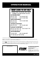
OPERATION MANUAL
NIGHTHAWK SERIES
MODELS LT-12D, LT-12P
DEDICATED LIGHT TOWER
(DEUTZ/LOMBARDINI DIESEL ENGINE)
(PERKINS DIESEL ENGINE)
Revision #1 (08/15/08)
To find the latest revision of this
publication, visit our website at:
www.multiquip.com
THIS MANUAL MUST ACCOMPANY THE EQUIPMENT AT ALL TIMES.
P/N: 49103
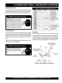
PROPOSITION 65 WARNING / REPORTING SAFETY DEFECTS
Diesel engine exhaust and some of
REPORTING SAFETY DEFECTS
If you believe that your vehicle has a defect that could cause a crash or could cause injury or
death, you should immediately inform the National Highway Traffic Safety Administration
(NHTSA) in addition to notifying Multiquip at 1-800-421-1244.
If NHTSA receives similar complaints, it may open an investigation, and if it finds that a safety
defect exists in a group of vehicles, it may order a recall and remedy campaign. However,
NHTSA cannot become involved in individual problems between you, your dealer, or
Multiquip.
To contact NHTSA, you may either call the Vehicle Safety Hotline toll-free at 1-888-327-4236
(TTY: 1-800-424-9153), go to http://www.nhtsa.dot.gov; or write to:
Administrator
NHTSA
1200 New Jersey Avenue S.E.
Washington, DC 20590
You can also obtain information about motor vehicle safety from http://www.safecar.gov.
PAGE 2 — LT-12 SERIES LIGHT TOWER — OPERATION MANUAL — REV. #1 (08/15/08)
TABLE OF CONTENTS
STOW NIGHTHA
WK
NIGHTHAWK
LT-12 SERIES LIGHT TOWER
Proposition 65 ................................................................. 2
Reporting Safety Defects ................................................ 3
Table of Contents ............................................................. 3
Safety Message Alert Symbols ................................... 4-5
Rules For Safe Operation ............................................. 6-7
Operation and Safety Decals ........................................ 8-9
Specifications (Light Tower) ........................................... 10
Specifications (Engines) ................................................ 11
Dimensions .................................................................... 12
General Information ....................................................... 13
Components .............................................................. 14-15
Control Panel ............................................................. 16-17
Floodlight Footcandle Plots ........................................... 18
Towing Guidelines ......................................................19-20
Trailer Safety Guidelines ............................................21-22
Trailer Wiring Diagram .................................................... 23
Inspection .................................................................. 24-27
Startup Procedure ......................................................... 28
Shutdown Procedure ..................................................... 29
Mast Operation .............................................................. 30
Operation ....................................................................... 31
Maintenance .............................................................. 32-36
Troubleshooting (Generator) ........................................... 37
Troubleshooting (Engine) ........................................... 38-39
Troubleshooting (Lamps) ............................................40-42
Schematic Diagram ....................................................... 43
Deutz Engine Wiring ...................................................... 44
Perkins Engine Wiring .................................................... 45
NOTE
For Deutz/Lombardini Parts
information, please see our LT-12
Deutz F3M1008F Diesel Engine
Parts Manual.
LT-12 SERIES LIGHT TOWER — OPERATION MANUAL — REV. #1 (08/15/08) — PAGE 3
LT-12 SERIES LIGHT TOWER — SAFETY MESSAGE ALERT SYMBOLS
FOR YOUR SAFETY AND THE SAFETY OF OTHERS!
Safety precautions should be followed
at all times when operating this
equipment. Failure to read and
understand the Safety Messages and
Operating Instructions could result in
injury to yourself and others.
This Owner's Manual has been
developed to provide complete
instructions for the safe and
efficient operation of the
LT-12 Series Light Tower.
NOTE
Before using this Light Tower, ensure that the operating
individual has read and understands all instructions in this
manual.
Potential hazards associated with the LT-12 Series Light
Tower operation will be referenced with Hazard Symbols
which appear throughout this manual, and will be referenced
in conjunction with Safety Message Alert Symbols.
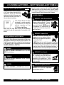
HAZARD SYMBOLS
WARNING - Lethan Exhaust Gasses
Engine exhaust gases contain
poisonous carbon monoxide. This gas
is colorless and odorless, and can
cause death if inhaled. NEVER operate
this equipment in a confined area or
enclosed structure that does not provide
ample free flow air.
WARNING - Explosive Fuel
SAFETY MESSAGE ALERT SYMBOLS
The three (3) Safety Messages shown below will inform you
about potential hazards that could injure you or others. The
Safety Messages specifically address the level of exposure
to the operator, and are preceded by one of three words:
DANGER, WARNING, or CAUTION.
DANGER
You WILL be KILLED or SERIOUSLY injured if you DO
NOT follow directions.
WARNING
You CAN be KILLED or SERIOUSLY injured if you DO
NOT follow directions.
CAUTION
You CAN be INJURED if you DO NOT follow directions.
Diesel fuel is extremely flammable, and
its vapors can cause an explosion if ignited.
DO NOT start the engine near spilled fuel
or combustible fluids.
DO NOT fill the fuel tank while the engine is running or
hot. DO NOT overfill tank, since spilled fuel could ignite if
it comes into contact with hot engine parts or sparks from
the ignition system. Store fuel in approved containers, in
well-ventilated areas and away from sparks and flames.
WARNING - Burn Hazards
Engine components can generate extreme
heat. To prevent burns, DO NOT touch
these areas while the engine is running or
immediately after operations. Never
operate the engine with heat shields or heat
guards removed.
CAUTION - Respiratory Hazard
ALWAYS wear approved respiratory
protection when required.
PAGE 4 — LT-12 SERIES LIGHT TOWER — OPERATION MANUAL — REV. #1 (08/15/08)
LT-12 SERIES LIGHT TOWER — SAFETY MESSAGE ALERT SYMBOLS
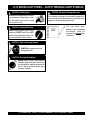
CAUTION - Rotating Parts
CAUTION - Equipment Damage Messages
NEVER operate equipment with covers,
or guards removed. Keep fingers, hands,
hair and clothing away from all moving
parts to prevent injury.
Other important messages are provided throughout this
manual to help prevent damage to your light tower, other
property, or the surrounding environment.
CAUTION - Accidental Starting
ALWAYS place the power source, circuit
breakers or ON/OFF switch in the OFF
position, when the generator is not in use,
unless connected to transfer switch.
NOTE
This light tower, other
property, or the surrounding
environment could be
damaged if you do not follow
instructions.
CAUTION - Sight and Hearing Hazards
ALWAYS wear approved eye and
hearing protection.
CAUTION - Over-Speed Conditions
NEVER tamper with the factory settings of
the engine governor settings. Personal injury
and damage to the engine or equipment can
result if operating speed ranges above
maximum allowable.
LT-12 SERIES LIGHT TOWER — OPERATION MANUAL — REV. #1 (08/15/08) — PAGE 5
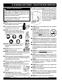
LT-12 SERIES LIGHT TOWER — RULES FOR SAFE OPERATION
WARNING - READ THIS MANUAL
Failure to follow instructions in this manual may lead to
Serious Injury or even Death. This equipment is to be
operated by trained and qualified personnel only! This
equipment is for industrial use only.
The following safety guidelines should always be used
when operating the LT-12 Lighttower.
■ The engine of this light tower/generator requires an adequate
free flow of cooling air. NEVER operate the generator in any
enclosed or narrow area where free
flow of the air is restricted. If the air
flow is restricted it will cause serious
damage to the generator engine
and may cause injury to people.
Remember the engine of the light
tower/generator gives off DEADLY
carbon monoxide gas.
Safety
■ DO NOT operate or service this equipment
before reading this entire manual.
■ This equipment should not be operated
by persons under 18 years of age.
■ ALWAYS refuel in a well-ventilated area, away from sparks
and open flames.
■ NEVER operate this equipment without
proper protective clothing, shatterproof glasses,
steel-toed boots and other protective devices
required by the job.
■ ALWAYS use extreme caution when
working with flammable liquids. When
refueling, stop the engine and allow it to
cool. DO NOT smoke around or near the
machine. Fire or explosion could result from
fuel vapors, or if fuel is spilled on a hot engine.
■ NEVER operate the light tower/generator in an explosive
atmosphere or near combustible materials. An explosion or
fire could result causing severe bodily harm or even death.
■ NEVER operate this equipment when not
feeling well due to fatigue, illness or taking
medicine.
■ NEVER operate the saw under the
influence or drugs or alcohol.
■ NEVER use accessories or attachments, which are not
recommended by Stow for this equipment. Damage to the
equipment and/or injury to user may result.
■ Manufacturer does not assume responsibility for any accident
due to equipment modifications. Unauthorized equipment
modification will void all warranties.
■ Whenever necessary, replace nameplate, operation and
safety decals when they become difficult read.
■ ALWAYS check all the bolts on the light tower for tightness.
■ NEVER touch the hot exhaust manifold,
muffler or cylinder. Allow these parts to
cool before servicing engine or
generator.
■ High Temperatures – Allow the engine
to cool before adding fuel or performing service and
maintenance functions. Contact with hot components can
cause serious burns.
■ Topping-off to filler port is dangerous, as it tends to spill fuel.
■ ALWAYS make sure that the light tower/generator is secure
on level ground so that it cannot slide or shift around,
endangering workers. Also keep the immediate area free of
bystanders.
■ ALWAYS use a trained technician to install and remove a
floodlight, or replace any damaged fixture wiring.
■ NEVER leave any grease or oil residue on glass surface
when replacing or removing bulbs. This can create hot spots,
reducing the service life of the bulb or causing outer jacket
to burst.
■ ALWAYS make sure trailer is leveled with all outriggers
extended before raising tower. Outriggers must remain
extended while tower is up.
■ ALWAYS keep area behind trailer clear of people while
raising and lowering mast.
■ NEVER remove safety pin or pull mast locking pin while
tower is in an raised position!
■ CHECK the mast and winch cables for wear. If any problem
occurs when lower or raising the tower STOP immediately!
Contact a trained technician for assistance.
■ NEVER pivot or retract mast while unit is operating.
PAGE 6 — LT-12 SERIES LIGHT TOWER — OPERATION MANUAL — REV. #1 (08/15/08)
LT-12 SERIES LIGHT TOWER — RULES FOR SAFE OPERATION
DANGER - High Danger Areas
The 5 DANGER items listed below are considered
High DANGER areas and should be adhered to. Failing to
understand these areas could result in Bodily Harm,
Electrical Shock, Electrocution, and even Death! Please
pay close attention when operating the light tower.
DANGER - Grounding the LT-12 for Operation
The LT-12 Light tower is equipped with
a ground terminal for your protection.
ALWAYS complete the grounding
path from the light tower to an external
grounding source.
ALWAYS make certain the light tower is well grounded and
securely fastened to a good earth ground (ground rod). The
possibility exists of Electrical Shock, Electrocution, and
even Death if the light tower is not grounded.
DANGER - Electric Shock Hazards
NEVER operate the LT-12 Light tower
or handle any electrical equipment
while standing in water, while bare
foot, while hands are wet, or in the
rain. A dangerous electrical shock
could occur causing Severe Bodily Harm or even Death.
ALWAYS keep electrical cords in good condition. Worn,
bare or frayed wiring can cause electrical shock, thus
WET
causing Bodily Harm or even Death.
HANDS
NEVER grab or touch a live power
cord with wet hands, the possibility
exists of Electrical Shock,
Electrocution, and even Death!
POWER
CORD
(POWER ON)
■ NEVER use the light tower mast as a crane. DO NOT lift
anything with the mast.
■ NEVER attach anything to the light tower mast.
DANGER - Overhead Obstruction Danger
ALWAYS make sure the area
above Light tower is open
and clear of overhead power
lines and other obstructions.
The tower extends in excess
of 30 ft. (9 meters). Contact
with overhead powerlines or
other obstructions could result
in equipment damage,
Serious Injury or Death!
■ NEVER touch bulbs while in use. Bulbs become extremely
hot when in use! Allow bulbs and fixture to cool at least 1015 minutes before handling.
■ ALWAYS retract the mast before lowering the tower to
transport position.
Maintenance Safety
■ NEVER lubricate components or attempt service on a running
light tower/generator.
■ ALWAYS allow the light tower/generator a proper amount of
time to cool before servicing.
■ Keep the light tower/generator in proper running condition.
■ Fix damage to the light tower/generator immediately and
always replace broken parts.
Emergencies
■ ALWAYS know the location of the
nearest fire extinguisher.
■ ALWAYS know the location of the nearest
first aid kit.
■ In emergencies always know the location of the nearest phone
or keep a phone on the job site. Also know the phone
numbers of the nearest ambulance, doctor and fire
department. This information will be invaluable in the case
of an emergency.
■ ALWAYS keep the immediate area surrounding the light
tower clean, neat, and free of debris.
■ ALWAYS lower the tower when not in use, or if high winds or
electrical storms are expected in the area.
■ NEVER pivot or retract mast while unit is operating.
LT-12 SERIES LIGHT TOWER — OPERATION MANUAL — REV. #1 (08/15/08) — PAGE 7
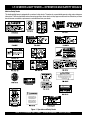
LT-12 SERIES LIGHT TOWER — OPERATION AND SAFETY DECALS
Machine Safety Decals
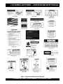
This dedicated light tower is equipped with a number of safety decals. These decals are provided for operator safety and maintenance
information. The illustration below and on the next page shows these decals as they appear on the machine. Should any of these
decals become unreadable, replacements can be obtained from your dealer.
Figure 1. Operation and Safety Decals
PAGE 8 — LT-12 SERIES LIGHT TOWER — OPERATION MANUAL — REV. #1 (08/15/08)
LT-12 SERIES LIGHT TOWER — OPERATION AND SAFETY DECALS
Figure 1. Operation and Safety Decals (Continued)
LT-12 SERIES LIGHT TOWER — OPERATION MANUAL — REV. #1 (08/15/08) — PAGE 9
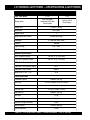
LT-12 SERIES LIGHT TOWER — SPECIFICATIONS (LIGHT TOWER)
TABLE 1. SPECIFICATIONS
Light Tower Model
Engine Model
LT-12D
LT-12P
Deutz F3m1008F/
Lombardini LDW 1003
Diesel Engine
Perkins 103-10
Diesel Engine
Weight (Dry)
1,550 lbs. (700 kg.)
Dimensions
See Table 3
Suppor t Points
Wind Stability with Genset.
Floodlights
Lumens
Light Coverage
Light Termination
5
65 mph (80.46 kph)
4-1,000 Watt Metal Halide
4 4 0 ,0 0 0
5 to 7 acres
4 x 3-pin QD plug
Generator Specifications
GFCI Receptacle Output
120 VAC @ 15 A (US only)
Twist-Lock Receptacle Output
240 VAC @ 25 A (US only)
GFCI Circuit Breaker (Amps)
15 A
Twist-Lock Circuit Breaker (Amps)
25 A
Continuous Output (Watts)
6,000 W
Noise Level @ 23 ft. (7 m)
73 db.
Trailer Specification
Jackstand Capacity
2,000 lbs. (907 kg.)
Hitch Type
2 in. Ball (Optional Pintle Kit availible)
Tire Size
13 in. (330 mm.)
Tire Rim Size
13 x 4.5 in. (330 x 114 mm)
Axle Capacity
2,000 lbs. (907 kg.)
Hub Type
5-Lug
Suspension Type
3-Leaf
Electrical Tail-light Connector
4-Wire
Winch Capacity
Winch Rope Wire
1,500 lbs. (680 kg.)
3/16 in.
PAGE 10 — LT-12 SERIES LIGHT TOWER — OPERATION MANUAL — REV. #1 (08/15/08)
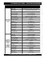
LT-12 SERIES LIGHT TOWER — SPECIFICATIONS (ENGINES)
Table 2. Engine Specifications
Engine Type
Bore X Stroke
2.95 in. X 2.83 in. (75 mm x 72 mm)
Displacement
58.21 cu. in. (954 cc)
Max Output Standby
10.5 H.P. at 1,800 R.P.M.
Fuel Tank Capacity
Approx. 30 U.S. Gallons (113 Liters)
Standard Idle Speed
Fuel Type
Lube Oil Capacity
64 Hours
1,800 R.P.M.
N0. 2 Diesel Fuel
7.4 U.S. Pints (3.5 Liters)
Cooling System
Water-cooled
Coolant Capacity
8.0 U.S. Pints (3.8 Liters)
Star ting Method
Electric Star t
Battery Type
Lombardini
Model LDW
1003/Diesel
Engine
or
Deutz Model
F3M008F
Diesel Engine
12 H.P. at 1,800 R.P.M.
Max Output Prime
Run Time With 4 Lights
Perkins Model
103-10 Diesel
Engine
Aspirated 4-stroke, 3-cylinder, 1 liter Diesel Engine
Group 12
Total Weight (Dry)
280 lbs. (127 Kg.)
Total Weight (Wet)
287 lbs. (130 Kg.)
Engine Type
3-cylinder, Diesel Engine
Displacement
62.73 cu. in. (1028 cc)
Max Output Standby
12 H.P. at 1,800 R.P.M.
Fuel Tank Capacity
Approx. 30 U.S. Gallons (113 Liters)
Run Time With 4 Lights
Standard Idle Speed
Fuel Type
Oil Sump Capacity
64 Hours
1,800 R.P.M.
N0. 2 Diesel Fuel
2.5 U.S. Quar ts (2.36 Liters)
Cooling System
Liquid-cooled
Star ting Method
Electric Star t
Battery Type
Total Weight (Dry)
Group 24
187.3 lbs. (85 Kg.)
LT-12 SERIES LIGHT TOWER — OPERATION MANUAL — REV. #1 (08/15/08) — PAGE 11
LT-12 SERIES LIGHT TOWER — DIMENSIONS
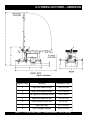
Figure 2. Dimensions
TABLE 3. DIMENSIONS
Reference Letter
Description
Dimension in. (mm.)
A
Length (Mast Stowed Position)
170 in. (431 cm.)
B
Length (Mast Deployed Position)
101 in. (256 cm.)
C
Max. Height (Mast Deployed Position)
31.5 ft. (9.6 m)
D
Height (Mast Stowed Position)
74 in. (187 cm.)
E
Ground Clearance (From Axle)
8 in. (20 cm.)
F
Width (Tow Ready)
51 in. (129 cm.)
G
Width (Outriggers Deployed)
109 in. (276 cm.)
PAGE 12 — LT-12 SERIES LIGHT TOWER — OPERATION MANUAL — REV. #1 (08/15/08)
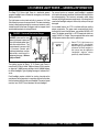
LT-12 SERIES LIGHT TOWER — GENERAL INFORMATION
The Stow LT-12 Series Light Tower is a dedicated general
purpose floodlight tower intended for emergency and remote
lighting conditions.
The light tower can be raised vertically in excess of 31.5 feet
(9.6 meters) by means of a manual winch. The tower tensioning
system is designed to provide the necessary tension to safely
control the pivot of the tower. Outriggers and rear support stand
must be deployed prior to raising the mast.
DANGER - Overhead Obstruction Danger
ALWAYS make sure the area
above Light tower is open and
clear of overhead power lines
and other obstructions. The
tower extends in excess of 30
ft. (9 meters). Contact with
overhead powerlines or other
obstructions could result in
equipment damage, Serious
Injury or Death!
For ease of service or transport, each floodlight is equipped
with a quick-disconnect connector that allows the lamp fixture to
be removed quickly. This feature is extremely useful during
transport of the light tower over rough terrain. It is always best to
remove the floodlights and pack them safely so they will not get
damaged.
As an added feature, the LT-12 is available with two auxiliary
output receptacles. The upper most receptacle(twist-lock),
located at the front of the light tower, can provide 240 VAC at 25
amps. The bottom receptacle is a GFCI receptacle which can
supply 120 VAC at 15 amps. These receptacles that can be used
for light power tools or other similar applications.
NOTE
Some LT-12 Light towers are
equipped with a Lombardini
Diesel Engine. All procedures &
references to Deutz engines in
this manual may be applied to
Lombardini engines unless
specifically noted otherwise.
The lighting system of Stow's LT-12 Series Light Tower is
comprised of 4 "Metal Halide" 1000 watt lamps. Each lamp has
an output of 110,000 lumens yielding a total of 440,000 lumens
for all four floodlights. Typical lighting coverage is between 5 to 7
acres.
Each floodlight requires a ballast for starting. Located on the
control panel of the generator is a weather resistant ballast box
that the contains the ballast for each floodlight. The control panel
contains four ON/OFF circuit breakers for each floodlight.
LT-12 SERIES LIGHT TOWER — OPERATION MANUAL — REV. #1 (08/15/08) — PAGE 13
LT-12 SERIES LIGHT TOWER — COMPONENTS
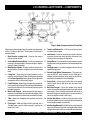
Figure 3. Major Components (Control Panel Side)
Figure 3 and 4 shows the location of the controls and components
for the LT-12 Series Light Tower. The functions of each control is
described below:
9. Tower Lock/Release Pin – Pull this pin to release tower
mast from cradle support.
1. Mast Rotation Locking Knob – Unscrew this knob to
release mast for rotation.
10. Jack Stands – There are two trailer jack stands, which are
located at the front and rear of the trailer. Use these 2 jack
stands to level and support the light tower.
2. Vertical Mast Extension Winch – Use this winch to extend
the mast to the desire height. Maximum height is approximately 31.5 feet (9.6 meters).
11. Chock Blocks – Place these blocks (not included as part of
the light tower package) under each trailer wheel to prevent
rolling.
3. Mast Rotation Handle – Grip this handle to rotate mast to
desired position. To lock mast tighten mast rotation locking
knob.
12. Outrigger Jacks – Use these 2 outrigger jacks to level and
support the light tower.
4. Lifting Bail – When lifting of the light tower by crane is
required, use this lifting bail. Note: this lifting bail is balanced
for a fully configured light tower; removal of any light tower
components will un-balance the lifting bail.
5. Forklift Pockets – When lifting of the light tower is required,
use these fork lift pockets to lift the light tower. Remember to
insert the forks of the fork lift a minimum of 24 inches into the
mast fork lift pockets.
6. Mast Cradle Support – When towing of the light tower is
required, place the tower mast into the cradle support. Make
sure tower release pin has been inserted and mast is locked.
7. T-Bar – Allows the floodlights to be mounted vertically or
horizontally.
8. Flood Light – 1000 watt "Metal Halide" type bulb with a
110,000 lumens capacity. Light coverage is typically between 5 to 7 acres.
13. Control Panel/ Ballast Compartment – This panel contains the ON/OFF circuit breakers for each flood light. In
addition, located behind the control panel are the ballasts
and electrical components for each floodlight.
14. Safety Chain – Always attach safety chain to the towing
vehicle. Never tow the light tower with the safety chain
unattached.
15. Ball Hitch Coupler – Attach this coupler to the towing
vehicle. Use only the specified ball diameter as indicated on
your coupler. Use of any other ball diameter will create an
extremely dangerous condition which can result in separation of the coupler and ball or ball failure.
16. Vertical Mast Winch – Use this winch to raise the mast the
to the vertical position. Once mast is in the full vertical position
the locking pin engages automatically.
17. Mast Locking/Release Pin – Pull this pin to start placing the
tower mast in the vertical position. Locking pin automatically
engages when tower mast has reached full vertical position.
PAGE 14 — LT-12 SERIES LIGHT TOWER — OPERATION MANUAL — REV. #1 (08/15/08)
LT-12 SERIES LIGHT TOWER — COMPONENTS
Figure 4. Major Components (Front/Rear)
18. Engine Exhaust Pipe – Directs engine exhaust to the rear
of the light tower. NEVER block this exhaust pipe with obstructions. ALWAYS place the generator in an area free of
obstructions.
CAUTION - Burn Hazard
The exhaust pipe will become extremely hot
when the engine is in use. NEVER touch the
exhaust pipe when the engine is running. The
possibility exists of severe burns to the skin.
Allow the exhaust pipe to cool before
touching.
21. Tires – This light tower uses a ST175-13C size tire. Replace
with only recommended tire size. NEVER tow light tower with
bad or worn tires.
22. Documentation Box – Contains information regarding the
light tower.
23. 240 VAC Twist-Lock Receptacle – This twist-lock receptacle provides 240 VAC, 25 amps.
24. 120 VAC GFCI Receptacle – This GFCI receptacle provides
120 VAC, 15 amps.
19. License Light – This light illuminates the license plate.
Whenever towing of the light tower is required, make sure this
light is operational.
20. Brake Lights – Before towing the light tower, make sure that
these lights are operational and are working correctly. NEVER
tow the light tower if these lights are inoperative.
LT-12 SERIES LIGHT TOWER — OPERATION MANUAL — REV. #1 (08/15/08) — PAGE 15
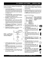
LT-12 SERIES LIGHT TOWER — CONTROL PANEL
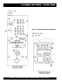
Figure 5. Control Panel Components and Indicators
PAGE 16 — LT-12 SERIES LIGHT TOWER — OPERATION MANUAL — REV. #1 (08/15/08)
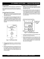
LT-12 SERIES LIGHT TOWER — CONTROL PANEL
Figure 5 shows the location of the basic control panel components
for the LT-12 Light Tower. Listed below is a brief explanation of
each control or component.
1.
Internal Cabinet Light Switch – This switch controls the
internal cabinet light for the light tower control panel. When
the cabinet door is raised, the light will automatically come
on. When the cabinet door closes, the switch is depressed
and the light turns off.
2.
Internal Cabinet Light – Provides illumination for the LT12 control panel during nighttime operation. The light is
activated when the cabinet door is raised.
3.
Hour Meter – This digital hour meter indicates the number
of hours machine has been in use.
4.
Main Circuit Breaker – A double-pole 25 amp, ON/OFF
circuit breaker which protects the 240 VAC twist-lock
receptacle from overload. In addition it allows voltage to be
supplied to the GFCI receptacle and 15 amp breakers (4).
5.
GFCI Receptacle Circuit Breaker – A single-pole, 15
amp, ON/OFF circuit breaker which protects the GFCI
receptacle from overload.
6.
Flood Light Circuit Breakers – A single-pole, 15 amp,
ON/OFF circuit breaker for each floodlight (4).
Items 7 - 11 refer to the
Perkins Engine Control
Panel only. See Figure 5.
10. Pre-Heat Indicator Light/Battery Charge Light –
Indicates when the glow plugs have been heated up for
starting the engine. If the light is flashing, a low battery
charge is detected.
11. Ignition Key Switch – Insert key into ignition switch and
turn clockwise to the ON position to warm the glow plugs.
When glow plug indicator light goes OFF, turn the key to
the START position. Release key when engine starts.
Items 12 - 18 refer to the
Lombardini Engine
Control Panel only. See
Figure 5.
12. Normal Operation Indicator Light – This
indicator light is illuminated when the engine is
functioning normally.
13. Low Oil Shutdown Indicator Light – This
indicator light is illuminated when the engine
has shut down due to low oil pressure. Service
as needed.
14. High Temperature Indicator Light – This
indicator light is illuminated when the engine has
shut down due to high water temperature. Service
as needed.
15. Alternator Indicator Light – This indicator light
is illuminated when the engine has shut down
due to high water temperature. Service as
needed.
7.
Air Filter Indicator Alarm Light – This alarm light flashes
when a problem with the air filter is detected. Service as
required.
8.
Water Temperature Alarm Light – This alarm light flashes
when the water temperature becomes to hot for normal
engine operation. Service as required.
9.
Oil Pressure Alarm Light – This alarm light flashes when
the oil pressure has fallen to low for normal engine
operation. Service as needed.
16. Glow Plug Indicator Light – This indicator light
is illuminated when the glow plugs have been
heated for starting the engine.
17. Air Filter Restriction Indicator Light – This
indicator light is illuminated when the engine
has shut down due to blockage in the air filter.
Service as needed.
18. Ignition Key Switch – Insert key into ignition
switch and turn clockwise to the ON position to
warm the glow plugs. When glow plug indicator
light goes OFF, turn the key to the START position.
Release key when engine starts.
LT-12 SERIES LIGHT TOWER — OPERATION MANUAL — REV. #1 (08/15/08) — PAGE 17
OK
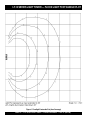
LT-12 SERIES LIGHT TOWER — FLOOD LIGHT FOOTCANDLE PLOT
Figure 6. Floodlight Footcandle Plot (Area Coverage)
PAGE 18 — LT-12 SERIES LIGHT TOWER — OPERATION MANUAL — REV. #1 (08/15/08)
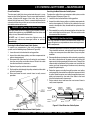
LT-12 SERIES LIGHT TOWER — TOWING GUIDELINES
Check with your county or state safety towing regulations
department before towing your light tower.
■ Inflate tires to correct pressure, inspect tires for cuts, and
excessive wear. See Table 3 (Tire Wear Troubleshooting).
■ Check wheel mounting lug nuts with a torque wrench.
Torque wheel lug nuts as described in the "Lug Nut Torque
Requirements", Table 5.
To reduce the possibility of an accident while transporting the
light tower on public roads, always make sure that the trailer and
the towing vehicle are in good operating condition and both
units are mechanically sound.
■ Avoid sudden stops and starts. This can cause skidding, or
jackknifing. Smooth, gradual starts and stops will improve
gas milage.
Towing Safety Precautions
CAUTION - Local Towing Regulations
The following list of suggestions should be used when towing
the light tower:
NOTE
Remember, when transporting of the
light tower is required, always
remove the floodlights and pack
them safely so they will not get
damaged.
■ Make sure that the hitch and coupling of the towing vehicle
are rated equal to, or greater than the trailer "gross vehicle
weight rating" (GVWR). See Table 1 for light tower weight.
■ ALWAYS inspect the hitch and coupling for wear. NEVER
tow the light tower's trailer with defective hitches, couplings,
chains etc.
■ CHECK the tire air pressure on both the towing vehicle and
the trailer. Also check the tire tread wear on both vehicles.
■ ALWAYS make sure the trailer section of the light tower is
equipped with a "Safety Chain".
■ ALWAYS attach trailer's safety chain to frame of towing
vehicle.
■ ALWAYS make sure that the vehicle and trailer directional,
backup, brake, and trailer lights are connected properly and
are working properly.
■ Check tightness of hanger bolt, shackle bolt, and U-blots
nuts, torque suspension hardware per Table 4.
■ Avoid sharp turns to prevent rolling.
■ Swivle all jackstands parallel to the ground before
transporting.
■ DO NOT transport light tower with fuel in the generator fuel
tank.
CAUTION - Defective/Damaged Trailer Couplings
If the trailer coupler is deformed replace entire coupler. NEVER
tow the light tower with a defective trailer coupler. There exist
the possibility of the trailer separating from the towing vehicle.
Light Tower Trailer Vehicle Connection
1. Check the vehicle hitch ball, and trailer coupler for signs of
wear or damage. Replace any parts that are worn or
damaged before towing.
2. Use only the 2-inch ball diameter as indicated on the trailer's
coupler. Use of any other ball diameter will create an
extremely dangerous condition which can result in
separation of the coupler and ball or ball failure.
3. Be sure the coupler is secured to the hitch ball and the lock
lever is down (locked).
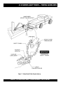
4. Attach safety chains as shown in Figure 7. Remember to
cross the safety chains.
■ Remember in most cases the maximum speed unless
otherwise posted for highway towing is 55 MPH, however
before towing your light tower, check your local state, and
county vehicle towing requirements. Recommended off-road
towing is not to exceed 15 MPH or less depending on type of
terrain.
5. After towing for about 50 miles recheck the entire towing
system for tightness.
■ Place chocked blocks underneath wheel to prevent rolling,
while parked.
2. When parking or storing the light tower, keep the coupler off
the ground so dirt and other debris will not build up in the
ball socket.
■ Depending on soil conditions and location it may be
necessary to place support blocks underneath the trailer's
bumper to prevent tipping, while parked.
Recommended Maintenance
1. Smear ball socket and clamp face with chassis grease.
Periodically oil pivot points and wear surfaces of the coupler
with SAE 30 W motor oil.
LT-12 SERIES LIGHT TOWER — OPERATION MANUAL — REV. #1 (08/15/08) — PAGE 19
LT-12 SERIES LIGHT TOWER — TOWING GUIDELINES
Figure 7. Safety Chains/ Trailer Coupler Hook-up
PAGE 20 — LT-12 SERIES LIGHT TOWER — OPERATION MANUAL — REV. #1 (08/15/08)
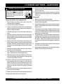
LT-12 SERIES LIGHT TOWER — TRAILER SAFETY GUIDELINES
Tires/Wheels/Lug Nuts
Tires and wheels are a very important and critical components
of the trailer. When specifying or replacing the trailer wheels it is
important the wheels, tires, and axle are properly matched.
WARNING - Wheel Repair/Modification
DO NOT attempt to repair or modify a
wheel. DO NOT install an inter-tube to
correct a leak through the rim. If the rim
is cracked, the air pressure in the intertube may cause pieces of the rim to
explode (break-off) with great force and
can cause serious eye or bodily injury.
Tires Wear/Inflation
Tire inflation pressure is the most important factor in tire life.
Pressure should be checked cold before operation. DO NOT
bleed air from tires when they are hot. Check inflation pressure
weekly during use to insure the maximum tire life and tread
wear.
Table 3 (Tire Wear Troubleshooting) will help pinpoint the causes
and solutions of tire wear problems.
Suspension
The leaf suspension springs and associated components
(Figure 8) should be visually inspected every 6,000 miles for
signs of excessive wear, elongation of bolt holes, and loosening
of fasteners. Replace all damaged parts (suspension) immediately. Torqued suspension components as detailed in Table 4.
WARNING - Safety Glasses Required
ALWAYS wear safety glasses when
removing or installing force fitted parts.
Failure to comply may result in serious
injury.
Figure 8. Major Suspension Components
LT-12 SERIES LIGHT TOWER — OPERATION MANUAL — REV. #1 (08/15/08) — PAGE 21
LT-12 SERIES LIGHT TOWER — TRAILER SAFETY GUIDELINES
TABLE 4. SUSPENSION TORQUE REQUIREMENTS
Item
Torque (Ft.-Lbs.)
3/8" U-BOLT
MIN-30 MAX-35
7/16" U-BOLT
MIN-45 MAX-60
1/2" U-BOLT
MIN-45 MAX-50
SHACKLE BOLT
SPRING EYE BOLT
SNUG FIT ONLY. PARTS MUST ROTATE FREELY.
LOCKING NUTS OR COTTER PINS ARE PROVIDED TO
RETAIN NUT-BOLT ASSEMBLY.
SHOULDER TYPE
MIN-30 MAX-50
SHACKLE BOLT
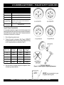
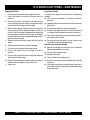
Lug Nut Torque Requirements
It is extremely important to apply and maintain proper wheel
mounting torque on the trailer. Be sure to use only the fasteners
matched to the cone angle of the wheel. Proper procedure for
attachment of the wheels is as follows:
1. Start all wheel lug nuts by hand.
2. Torque all lug nuts in sequence. See Figure 9. DO NOT
torque the wheel lug nuts all the way down.Tighten each lug
nut in 3 separate passes as defined by Table 5.
TABLE 5. TIRE TORQUE REQUIREMENTS
Wheel Size
First Pass
FT-LBS
Second Pass
FT-LBS
Third Pass
FT-LBS
12"
20-25
35-40
50-65
13"
20-25
35-40
50-65
14"
20-25
50-60
90-120
15"
20-25
50-60
90-120
16"
20-25
50-60
90-120
3. After first road use, retorque all lug nuts in sequence. Check
all wheel lug nuts periodically.
Figure 9. Wheel Lug Nuts Tightening Sequence
NOTE
NEVER! use an pneumatic air gun
to tighten wheel lug nuts.
PAGE 22 — LT-12 SERIES LIGHT TOWER — OPERATION MANUAL — REV. #1 (08/15/08)
LT-12 SERIES LIGHT TOWER — TRAILER WIRING DIAGRAM
Figure 10. Typical Trailer Wiring Diagram
LT-12 SERIES LIGHT TOWER — OPERATION MANUAL — REV. #1 (08/15/08) — PAGE 23
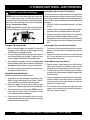
LT-12 SERIES LIGHT TOWER — INSPECTION
Before Starting
1. Read all safety instructions at the
beginning of manual.
2. Clean the light tower, removing dirt and dust,
particularly the engine cooling air inlet and
air cleaner.
Figure 11. Dipstick
3. Check the air filter for dirt and dust. If air filter is dirty, replace
air filter with a new one as required.
4. Check all fastening nuts and bolts for tightness.
WARNING - Ventillation Requirements
5. When checking the engine oil, be sure to check if the oil is
clean. If the oil is not clean, drain the oil by removing the oil
drain plug, and refill with the specified amount of oil as
outlined in the Perkins or Lombardini-Deutz Engine
Owner's Manuals. Oil should be warm before draining.
Ensure adequate ventilation when operating
the lighttower in enclosed areas. The engine
exhaust contains noxious elements.
Indoor Installation
Exhaust gases from diesel engines are extremely poisonous.
Whenever an engine is installed indoors the exhaust fumes must
be vented to the outside. The engine should be installed at least
two feet from any outside wall. Using an exhaust pipe which is
too long or too small can cause excessive back pressure which
will cause the engine to heat excessively and possibly burn the
valves.
Eliminate the danger of deadly carbon monoxide gas. Remember
that exhaust fumes from any gasoline or diesel engine are very
poisonous if discharged in a closed area. If the light tower is
installed indoors, you must make provisions for venting the
engine exhaust to the outside of the building.
Engine Oil Check
1. To check the engine oil level, place the make sure the light
tower is placed on secure level ground with the engine
stopped.
2. Remove the filler cap/dipstick from its holder and wipe it
clean.
3. Insert and remove the dipstick from its holder. Check the oil
level shown on the dipstick.
4. If the oil level is low, add oil through the oil filler hole, DO NOT
overfill. Fill to the normal operating level as shown on the
dipstick (Figure 28). Verify that the oil level is maintained
between the two notches as shown in Figure 11. Always fill
with recommended type oil as listed in Table 6. Reference
Table 2 for engine oil capacity.
Other types of motor oils may be substituted if they meet the
following requirements:
z
z
z
z
z
API Service Classification CH-4
API Service Classification CG-4
API Service Classification CF-4
ACEA Specification E3
ACEA Specification E2
PAGE 24 — LT-12 SERIES LIGHT TOWER — OPERATION MANUAL — REV. #1 (08/15/08)
LT-12 SERIES LIGHT TOWER — INSPECTION
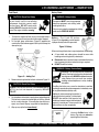
Battery Check
Fuel Check
CAUTION - Diesel Fuel Safety
Diesel fuel and its vapors are dangerous
to your health and the surrounding
environment. Avoid skin contact and/or
inhaling fumes. DO NOT smoke while
refueling. DO NOT attempt to refuel the light
tower if the engine is hot! or running.
WARNING - Battery Safety
The operator MUST wear the appropriate
protective equipment and clothing while
handling the battery.
Failure to wear protective equipment or clothing
could result in SERIOUS INJURY.
1. To check the engine fuel level, make sure the light tower is
Battery - The 12-volt DC battery
placed on secure level ground with the engine stopped.
(Figure 13) is shipped dry, and will require
2. Lift the light tower access door (Figure 12) opposite the a proper electrolyte level for operation.
control panel. Set the door support latch in place to keep the
door open (up).
Figure 13. Battery
When servicing of the battery is required perform the following:
z A face shield and rubber gloves should be worn while
handling and servicing battery's electrolyte.
z Disconnect battery terminal clamps, and remove the battery
from the generator cabinet when servicing is required.
z DO NOT overfill the battery.
WARNING - Battery Service Safety
Electrolyte is an acid and must be handled with
caution. Servicing instructions from the electrolyte
manufacturer must ALWAYS be followed to ensure
safety. Serious injury can result from careless
handling and noncompliance to safety handling
instructions.
Figure 12. Adding Fuel
3. Remove the fuel cap from the fuel tank as shown in Figure 12.
CAUTION - Diesel Fuel Safety
ALWAYS fill the fuel tank with clean, fresh #2 diesel fuel. DO
NOT fill the fuel tank beyond its capacity. DO NOT
TOP-OFF.
4. Pay attention to the fuel tank capacity when replenishing fuel.
The fuel tank cap must be closed tightly after filling. Handle
fuel in a safety container. If the container does not have a
spout, use a funnel. Wipe up any spilled fuel immediately.
Overfilling the battery may cause the electrolyte to overflow
resulting in corrosion to nearby components. Immediately wash
off any spilled electrolyte (battery acid).
Additionally, when connecting the positive (+)
cable to the battery's positive (+) terminal post,
DO NOT allow contact of the wrench or any
metallic part to come in contact with the battery's
negative (-) terminal post. This may result in an
electrical short circuit or an explosion.
5. Wipe up any spilled fuel immediately!
NOTE
Use only distilled water in the
battery. Tap water can reduce the
operating life of the battery.
LT-12 SERIES LIGHT TOWER — OPERATION MANUAL — REV. #1 (08/15/08) — PAGE 25
LT-12 SERIES LIGHT TOWER — INSPECTION
Coolant (Ethylane Glycol [Green] / Water — 50/50 mix)
Use only drinkable tap water. If hard water or water with many
impurities is used, the inside of the engine and radiator may
become coated with deposits and cooling efficiency will be
reduced.
An anticorrosion additive added to the water will help prevent
deposits and corrosion in the cooling system. See the engine
manual for further details.
WARNING - Radiator Burn Hazard
If adding coolant/antifreeze mix to the
radiator, DO NOT remove the radiator cap
until the unit has completely cooled. The
possibility of hot! coolant exists which can
cause severe burns.
NOTE
When the antifreeze is mixed with
water, the antifreeze mixing ratio
must be less than 50%.
Cleaning the Radiator
The engine may overheat if the radiator fins become overloaded
with dust or debris. Periodically clean the radiator fins with
compressed air. Cleaning inside the machine is dangerous, so
clean only with the engine turned off and the negative battery
terminal disconnected.
Air Cleaner
Periodic cleaning/replacement is necessary. Inspect it in
accordance with the Perkins, Lombardini or Deutz Engine
Owner's Manuals.
Day-to-day addition of coolant is done from the recovery tank.
When adding coolant to the radiator, DO NOT remove the radiator
cap until the unit has completely cooled. See Table 7 for engine
and radiator, coolant capacities. Make sure the coolant level in
the recovery tank is always between the "H" and the "L" markings.
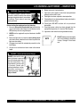
Fan Belt Tension
A slack fan belt may contribute to overheating, or to insufficient
charging of the battery. Inspect the fan belt for damage and wear
and adjust it in accordance with the Perkins, Lombardini or
Deutz Engine Owner's Manuals.
The fan belt tension is proper if the fan belt bends 10 to 15 mm
(Figure 14) when depressed with the thumb as shown below.
TABLE 7. COOLANT CAPACITY
Engine Type
Coolant Capacity
Perkins 103-10
5 qt. (4.7 Liters)
Lombardini LDW 1003
5.18 qt. (4.9 Liters)
DEUTZ F3M1008F
5.18 qt. (4.9 Liters)
Figure 14. Fan Belt Tension
Operation Freezing Weather
When operating in freezing weather, be certain the proper amount
of antifreeze (Table 8) has been added.
NEVER place hands near the belts or fan while the engine is
running.
TABLE 8. ANTI-FREEZE
OPERATING TEMPERATURES
Freezing Point
Boiling Point
°C
°F
°C
°F
40
-24
-12
106
222
50
-37
-34
108
226
Vol %
Anti-Freeze
WARNING - Rotating Parts Hazard
PAGE 26 — LT-12 SERIES LIGHT TOWER — OPERATION MANUAL — REV. #1 (08/15/08)
LT-12 SERIES LIGHT TOWER — INSPECTION
WARNING - Respiratory Hazard
The engine's exhaust contains harmful
emissions. ALWAYS ventilate the exhaust
when operating inside tunnels, excavations
or buildings. Direct exhaust away from
nearby personnel.
Before starting the engine perform the following:
1. Be sure to disconnect the electrical load and switch the
main circuit breaker and all lamp (4) circuit breakers to the
OFF position prior to starting the engine.
6. Bottom tower mast is locked in place.
7. Light tower trailer support stands have been positioned
properly and the trailer is level.
8. Flood lights have been adjusted to desired position.
9. Chocked blocks have been positioned under each wheel to
prevent trailer from rolling.
10. Flood lights DO NOT interfere with any overhead
obstructions.
11. Flood light power cables have been plugged into the
appropriate receptacles (J1-J4) on the T-Bar assembly.
12. Light tower trailer frame has been grounded correctly.
2. NEVER start the engine with any circuit breakers in the ON
position.
3. Make sure light tower is placed on secure level ground
with chock blocks underneath each wheel to prevent the
light tower from rolling.
4. Outriggers have been fully extended to prevent the trailer
from tipping.
NOTE
DO NOT attempt to start the engine
until all the conditions referenced
in steps 1 through 12 have been
met.
5. All tower mast sections have been raised to the desired
height.
DANGER - Overhead Obstruction Danger
ALWAYS make sure the area
above Light tower is open and
clear of overhead power lines
and other obstructions. The
tower extends in excess of 30
ft. (9 meters). Contact with
overhead powerlines or other
obstructions could result in
equipment damage, Serious
Injury or Death!
LT-12 SERIES LIGHT TOWER — OPERATION MANUAL — REV. #1 (08/15/08) — PAGE 27
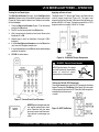
LT-12 SERIES LIGHT TOWER — STARTUP PROCEDURES
Starting the Engine
Starting the Engine (Lombardini/Deutz Engines)
The Night-Hawk LT-12 Series Light Tower is available with two
types of engines (Perkins or Lombardini/Deutz). The engine starting procedure contained within this manual will address both
engines..
1. Open the access panel door on the right-side of the light
tower (opposite the fuel tank). Set the door latch in place to
hold the door open (up)
Starting the Engine (Perkins Engines)
1. Open the access panel door on the right-side of the light
tower (opposite the fuel tank). Set the door latch in place to
hold the door open (up)
2. Insert the ignition key into the ignition switch (Figure 16).
Turn the ignition key clockwise one click to the ON position.
The pre-heat indicator lamp will be lit, wait for this indicator
lamp to go OFF. When the lamp goes OFF this indicates
that the glow plugs have been pre-heated and the engine
can now be started.
2. Insert the ignition key into the ignition switch (Figure 15).
Turn the ignition key clockwise to the ON position. The preheat indicator lamp will be lit, wait for this indicator lamp to
go OFF. When the lamp goes OFF this indicates that the
glow plugs have been pre-heated and the engine can now
be started.
Figure 16. Lombardini/Deutz Ignition Switch
3. Continue turning the ignition key all the way clockwise, when
the engine has started, release the key.
Figure 15. Perkins Ignition Switch
4. Before placing the light tower into actual operation, let the
engine run for 3-5 minutes. Listen of any abnormal sounds
or smells that would be associated with a defective light
tower. If any abnormal conditions occur, shut-down the light
tower and correct the problem.
3. Continue turning the ignition key in a clockwise direction to
the START position, when the engine has started, release
the key.
4. Before placing the light tower into actual operation, let it run
for 3-5 minutes. Listen of any abnormal sounds or smells
that would be associated with a defective light tower. If any
abnormal conditions occur, shut-down the light tower and
correct the problem.
PAGE 28 — LT-12 SERIES LIGHT TOWER — OPERATION MANUAL — REV. #1 (08/15/08)
LT-12 SERIES LIGHT TOWER — SHUTDOWN PROCEDURES
Normal Shut-down
Emergency Shut-down
1. If a load is attached to the generating set of the light tower,
remove the load.
1. Turn the ignition key to the OFF position.
2. Set CB-1 thru CB-4 on the control panel to the OFF position.
3. Place the MAIN circuit breaker (Figure 5, Item 4) on the
control panel to the OFF position.
4. Wait a few seconds and observe that flood all floodlights
are OFF.
5. Let the engine idle for a few minutes with no load.
6. Turn the ignition key to the OFF position. Store key in a safe
location.
7. Lower light tower mast and place in stow position as outlined
in the Pre-Setup section of this manual.
8. Place outriggers in tow position, and remove chock blocks.
9. Store light tower in a clean, dry location out of the reach of
children and bystanders.
NOTE
Allow flood lights to cool (15
minutes) if service or removal of
bulb is required.
LT-12 SERIES LIGHT TOWER — OPERATION MANUAL — REV. #1 (08/15/08) — PAGE 29
LT-12 SERIES LIGHT TOWER — MAST OPERATION
DANGER - Overhead Obstruction Danger
ALWAYS make sure the area above Light tower is open and
clear of overhead power lines and other obstructions. The
mast extends in excess of 30 ft. (9 meters). Contact with overhead
powerlines or other obstructions could result in equipment
damage, Serious Injury or Death!
DO NOT stand behind the trailer while the mast is being raised
or lowered. Serious Injury could result if the mast falls down.
Raising Mast (Top and Center Tower Sections)
Once the tower mast has been locked into its vertical position,
the top and center tower sections can now be raised. These two
tower sections allow the flood lights to be extended upwards in
excess of 30 ft. Perform the following steps when extending the
floodlights:
1. Locate the "vertical mast extension hand winch", see Figure
3, Item 2.
2. Turn the vertical mast extension hand winch lever clockwise,
and observe that the flood lights begin to climb upward.
3. Continue turning the hand winch lever in the clockwise
direction until the desired height has been reached.
4. Release the hand winch lever, this winch is of the self-locking
type. The tension on the cable will keep the mast sections in
place.
Outriggers and Support Stands
Lowering Mast (Top and Center Tower Sections)
1. Make sure both outriggers are extended. To extend the
outriggers, pull the locking pin on the outrigger and hold
while sliding out the outrigger assembly.
1. Turn the vertical mast extension hand winch lever counterclockwise, and observe that the flood lights begin to drop
downward.
2. As soon as the pin clears the travel position hole, release it
and continue sliding out the outrigger. The pin must snap
into the outrigger locking hole in the extended position.
2. Continue turning the hand winch lever counter-clockwise
until the top and center mast sections have been fully
retracted (slack in the cable).
3. After extending all outriggers, rotate all trailer jack stands
into the foot down position, then turn the crank handle on the
jack stands clockwise to lower it and level the light tower.
Lowering Mast (Lower Lower Section)
4. Check behind the light tower and make sure all personnel
and objects are clear of the mast.
Raising Mast (Lower Mast Section)
Follow the steps below to raise the lower mast:
1. To release the mast from the support stand locking cradle,
PULL the large cradle locking pin (see Figure 3, item 9).
This will unlock the mast from the horizontal position.
2. Remove the bottom mast quick release locking pin (see
Figure 3, Item 17) before raising tower to the vertical position.
3. To place the mast in the vertical position, TURN the vertical
winch hand lever (Figure 3, item 16) clockwise until the
mast is pointing upwards at 90 degrees.
1. Remove the quick release locking pin to allow the mast
section to be lowered to the horizontal section. Hold the
locking pin open until the swivel base tab clears the lock.
2. Turn the vertical mast hand winch lever counter-clockwise,
and observe that bottom tower mast begins to approach the
horizontal position.
3. Continue turning the vertical hand winch lever in the counterclockwise direction. As the lower tower mast approaches
the locking cradle, pull the tower release pin to allow the
tower mast to rest in the cradle.
4. Once the lower mast is resting in the cradle of the tower
support stand, align the hole on the mast with the hole on
the cradle and insert locking pin.
4. Once the mast in the vertical position and the mast lock
captures the swivel base tab, insert the quick release locking
pin to prevent the mast from falling.
PAGE 30 — LT-12 SERIES LIGHT TOWER — OPERATION MANUAL — REV. #1 (08/15/08)
LT-12 SERIES LIGHT TOWER — OPERATION
Turning On the Flood Lights
Applying an External Load
The Main Circuit Breaker (25 amps), and 4 floodlight circuit
breakers (10 amps each) are located on the upper control panel
(Figure 20). Please note that there is one 10 amp circuit breaker
for each floodlight.
The Night-Hawk LT-12 Series Light Tower is available with two
auxiliary output receptacles (Figure 18). The upper most
receptacle (twist-lock) located at the front of the light tower can
provide 240 VAC at 25 amps. The bottom receptacle is a GFCI
receptacle which can supply 120 VAC at 15 amps.
1. Place the Main circuit breaker (Figure 17) on the control
panel to the ON position.
2. Set CB-1 on the control panel to the ON position.
3. Wait a few minutes for the ballast to activate. Observe that
flood light #1 is ON.
5. Repeat steps 2 and 3 for flood lights 2 through 4 (CB-2
through 4).
6. If all the flood light circuit breakers are in the ON position
(up), then all of the lights should be on.
7. If any of the flood lights are not ON refer to the troubleshooting
section of this manual.
8. CLOSE all cabinet doors.
Figure 18. 120/240 VAC Output Receptacles
DANGER - Electric Shock Hazards
WET
HANDS
NEVER grab or touch a live power
cord with wet hands, the possibility
exists of electrical shock,
electrocution, and even death!
POWER
CORD
(POWER ON)
Testing the 120 VAC GFCI Receptacle
Pressing the reset button resets the GFCI receptacle after being
tripped. Pressing the "Test Button" (See Figure 19) in the center
of the receptacle will check the GFCI function. Both receptacles
should be tested at least once
a month.
Figure 17. Control Panel Circuit Breakers
NOTE
NEVER operate the light tower with
the engine compartment doors
open. Operation with the doors
open may cause insufficient cooling to the unit, and damage may
result.
Figure 19. GFCI Test Button
LT-12 SERIES LIGHT TOWER — OPERATION MANUAL — REV. #1 (08/15/08) — PAGE 31
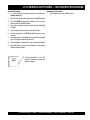
LT-12 SERIES LIGHT TOWER — MAINTENANCE
Use Table 9 shown below as a general checklist to be performed
on a daily basis. For more detailed maintenance refer to the
Perkins or Lombardini/Deutz engine service manuals.
TABLE 9. INSPECTION / MAINTENANCE
10 Hrs
DAILY
Check Engine Fluid Levels
X
Check Fuel Filter
X
Check Air Cleaner Dust Indicator (if equipped)
X
Check for Leaks/Visual Walk Around
X
Check for Loosening of Par ts
X
ENGINE
GENERATOR
200 Hrs
Replace Engine Oil and Filter *1
X
Service Battery
X
Clean Unit, Inside and Outside
X
500 Hrs
Change Fuel Filter *2
X
Clean Radiator and Check Coolant Protection
Level
X
1000 Hrs
Replace Air Filter Element
X
Test Thermostats
X
Check all Hoses and Clamps/Flush Radiator
X
Clean Inside of Fuel Tank
X
Measure Insulation Resistance Over 3M ohms
X
*1 Replace engine oil anf filter at 100 hours, first time only.
*2 Replace fuel filter at 250 Hours, first time only.
PAGE 32 — LT-12 SERIES LIGHT TOWER — OPERATION MANUAL — REV. #1 (08/15/08)
LT-12 SERIES LIGHT TOWER — MAINTENANCE
Check Cable Wear
Servicing the Mast Extension Cable System:
The wire rope (cable) that raises and extends the mast is a very
important part of the light tower. There is one cable/hand winch
system, located on the tounge of the trailer, that raises and
extends the light tower mast. There is a second cable/hand winch
system located on the mast that serves to raise and lower the two
extendable sections of the mast.
To replace the cable in the mast extension cable system, use the
following steps (Reference Figure 21):
1. Lower the mast to the horizontal resting position.
DANGER - Light Tower Cable System Safety
2. Inspect the cable clamps, pulleys, and other components for
worn or damaged parts. If either of the cables on the mast
needs to be replaced, they should both be replaced at the
same time.
Wire rope (cable) will fail if it is worn, frayed, misused, crushed,
kinked or damaged in any way. ALWAYS check the cables and
pulleys for any abnormalities before use.
3. Disassemble the mast by disconnecting the cables form the
mast and sliding the sections apart. The lower cable can be
disconnected from the winch.
DO NOT use it if there is even the slightest cause for
concern and replace any damaged cables or pulleys
immediately.
WARNING - Mast Service Safety
The mast sections are heavy and awkward to handle. Use
proper lifting devices and procedures when servicing the mast
and its components.
Servicing the Mast Raise/Lower Cable System:
To replace any components in the mast raise/lower cable
system, use the following steps (Reference Figure 20):
1. Lower the mast to the horizontal resting position.
2. Inspect the cable clamps, pulleys, and other components for
worn or damaged parts.
3. Disconnect the cable from the ball socket pin and remove
from the mast pulley and cable sheave. Detatch the cable
from the hand winch as necessary.
4. Replace the pulley and the cable as needed.
5. Re-thread the cable through the pulley and reattach the cable
to the ball socket pin.
6. Raise and lower the mast several times to verify correct
operation.
4. There are two pulleys in the mast raise/lower cable system.
They should be removed, and replaced if worn or damaged,
as they can cause premature cable failure if they are in poor
condition.
5. Reassemble the mast extension cable system by connecting
the cable to the bottom of the upper mast and sliding the
upper mast into the opening of the center mast. Connect the
second cable to the bottom of the center mast and slide the
center mast into the opening of the lower mast, observing
proper lifting techniques.
6. Route the upper mast cable through the center mast pulley
and connect the free end of the cable to the lower mast ankle
shackle. Route the center mast cable through the lower mast
pulley and connect the free end of the cable to the hand
winch at the bottom of the lower mast.
7. Raise, extend, retract and lower the mast several times to
verify correct operation.
CENTER
MAST
PULLEY
UPPER
MAST
LOWER
MAST
PULLEY
CENTER
MAST
LOWER
MAST
SHACKLE
ROUTE TO
HAND WINCH
LOWER
MAST
Figure 21 Mast Extension Cable System
Figure 20. Mast Raise/Lower Cable System
LT-12 SERIES LIGHT TOWER — OPERATION MANUAL — REV. #1 (08/15/08) — PAGE 33
LT-12 SERIES LIGHT TOWER — MAINTENANCE
General Inspection
Prior to each use, the generating set should be cleaned and
inspected for deficiencies. Check for loose, missing or damaged
nuts, bolts or other fasteners. Also check for fuel or oil leaks.
Air Cleaner
Every 50 hours: Check dust indicators on control panel. If light is
ON, clean the air cleaner element.
1. Un-latch the holding clips and take out the air cleaner
element.
2. Clean the inside of the body and cover using a damp cloth.
2
3. Blow dry with compressed air (0.69Mpa {7kgf.cm ,
99.4 PSI} maximum) against the side of the element along
the pleats. Then blow dry against outside along the pleats,
then against inside again.
4. Remove one seal each time the element is cleaned.
5. Replace the outer element after cleaning it 6 times or after
one year. Replace the outer element if indicator is red even
after cleaning it.
6. If seal washer is damaged or the threads of wing nut are
damaged, replace.
7. Remove evacuator valve and clean it with compressed air.
Reinstall.
Fuel Addition
Add diesel fuel (the grade may vary according to season and
locations). Always pour through the mesh filter.
Removing Water from the Tank
After prolonged use, water and other impurities accumulate in
the bottom of the tank. Occasionally remove the drain cock and
drain the contents. During cold weather, the greater the empty
volume inside the tank, the easier it is for water to condense.
This can be reduced by always keeping the tank as full as
possible.
Air Removal
If air enters the fuel injection system of a diesel engine, starting
becomes impossible. After running out of fuel, or after
disassembling the fuel system, bleed the system according to
the following procedure.
To restart after running out of fuel, squeeze the fuel primer bulb
to pump fuel into the engine. This unit is equipped with an
automatic air bleeding system.
Service Daily
If engine is operating in very dusty and dry grass conditions, a
clogged air cleaner will result in high fuel consumption, loss of
power and excessive carbon buildup in the combustion chamber.
Cleaning the Fuel Strainer
Clean the fuel strainer if it contains dust or water. Remove dust or
water in the strainer cap and wash it in diesel. Securely fasten
the fuel strainer cap so that fuel will not leak. Check the fuel
strainer every 200 hours of operation or once a month.
Check Oil Level
Check the crankcase oil level prior to each use, or when the fuel
tank is filled. Insufficient oil may cause severe damage to the
engine. Make sure the generator is level. The oil level must be
between the two notches on the dipstick as shown in Figure 14.
PAGE 34 — LT-12 SERIES LIGHT TOWER — OPERATION MANUAL — REV. #1 (08/15/08)
LT-12 SERIES LIGHT TOWER — MAINTENANCE
WARNING - Radiator Burn Hazard
Allow engine to cool when flushing out
radiator. Flushing the radiator while hot!
will damage radiator. In addition the
possibility of hot! coolant exists which can
cause severe burns.
Flushing Out Radiator and Changing Coolant
1. Stop the engine and allow to cool. Tighten valve of the
corrosion resistor (if equipped).
2. Turn water filer cap slowly and remove it.
3. Prepare a container to catch the coolant, then open drain
plug of the radiator or heat exchanger and drain plug of the
engine, and drain the coolant.
4. After draining the coolant, close drain plugs and fill with tap
water.
5. When the water level is near the mouth of the water filler,
open drain plugs and start the engine, and run at low idling.
Keep the engine running at low idling and flush the radiator
for about 10 minutes.
6. Adjust the flow of the water flowing in and draining out to
ensure that the radiator is always full during the flushing
operation. While flushing water through the system, watch
carefully the water inlet hose does not come out of the radiator
filler port.
7. After flushing, stop the engine, open drain plug and drain
the water, then close drain plugs.
14. Drain the water inside reserve tank, clean the inside of the
reserve tank, then fill with coolant/water mixture to between
the full and low lines.
15. Stop the engine, wait for 3 minutes, add tap water until the
water level reaches near the water filer port, then tighten the
radiator cap.
Changing Oil
1. Make sure the oil is cool before changing.
2. Set a container directly under the drain plug of the oil pan.
Loosen the drain plug slowly.
3. Check the drained oil for excessive metal particles or foreign
material. Contact the distributor if there is metal particles or
foreign material.
4. Using a filter wrench, turn filter cartridge to the left to remove
it. If the filter cartridge is filled with a large amount of oil, wait
10 minutes or so before removing. Make sure there is no old
gasket stuck on the filter holder.
5. Tighten drain plug. Clean the filter holder, fill the new filter
cartridge with clean engine oil, coat the packing and thread
of the new filter cartridge with engine oil, then install it to the
filter holder. Tighten until the gasket surface contacts the
seal surface of the filter holder, then tighten it a further 3/4 to
1 turn.
6. Add engine oil through oil filler until the oil level is between
the H and L marks on the dipstick.
7. Run the engine at idling for a short time, then stop the engine.
Recheck the oil level and fill as necessary.
8. After draining the water, flush the system with a flushing
agent. See instructions on flushing agent label.
9. After flushing, open drain plugs and drain out all the water,
then close drain plugs and add tap water so the water level
is near the mouth of the water filler.
10. When the water level is near the mouth of the water filler,
open drain plugs and start the engine, run at low idling and
continue to flush the system until clean water comes out.
Adjust the flow of the water flowing in and draining out to
ensure the radiator is always full during the flushing
operation.
11. When clean water comes out, stop the engine, drain all the
water, then close drain plugs.
12. Remove the corrosion resistor (if equipped) and open valve.
13. Supply water until it flows over the water filler.
LT-12 SERIES LIGHT TOWER — OPERATION MANUAL — REV. #1 (08/15/08) — PAGE 35
LT-12 SERIES LIGHT TOWER — MAINTENANCE
Replacing Fuel Filter
Light Tower Storage:
1. Set the container under the filter cartridge to catch fuel.
For storage of the generator for over 30 days, the following is
required:
2. Using a filter wrench, turn the filter cartridge to the left to
remove it.
3. Clean the filter holder, fill the new filter cartridge with fuel,
coat the packing surface of the filter cartridge with engine
oil, then install the cartridge to the filter holder.
4. When installing, tighten until the packing surface contacts
the seal surface of the filter holder then tighten a further 2/3
of a turn. If the filter cartridge is tighten too much, the packing
will be damaged and will cause fuel leakage. Fuel leakage
will occur if the filter cartridge is not tightened enough. Always
tighten to the correct angle.
z Fill the fuel tank completely. Treat with fuel stabilizer if
necessary.
z Completely drain oil from the crankcase and refill if necessary
with fresh oil.
z Clean the entire light tower, internal and external.
z Disconnect the negative terminals of the battery and cover
it, or remove it from the generator and store it separately.
z If the ambient temperature is expected to drop below 0oC,
add antifreeze to the radiator.
5. Squeeze the fuel primer bulb to pump fuel back into the
engine.
z Cover the light tower and store in a clean, dry place away
from children and non-qualified personnel.
6. Replace Corrosion resistor cartridge (if equipped)
Removal From Long Term Storage:
7. Screw in valves at the top of the corrosion resistor.
z Apply oil to the engine valve and rocker arms, and examine
the operating condition of the valves.
8. Using a filter wrench, turn the cartridge to the left to
remove it.
9. Coat the seal surface of the new cartridge with engine oil
and install it to the filter holder.
z Change the oil in engine oil pan.
z Replace all the filters.
z Flush the inside of the cooling system.
10. Tighten until he packing surface contacts the seal surface of
the filter holder, then tighten a further 2/3 of a turn.
z Drain the water from the fuel tank and bleed the air from the
fuel system.
11. Open valves.
z If the engine has not been started for more than one year,
contact your Perkins or Lombardini/Deutz distributor to have
engine overhauled.
PAGE 36 — LT-12 SERIES LIGHT TOWER — OPERATION MANUAL — REV. #1 (08/15/08)
LT-12 SERIES LIGHT TOWER — TROUBLESHOOTING (GENERATOR)
Practically all breakdowns can be prevented by proper handling and maintenance inspections, but in the event of a
breakdown, please take a remedial action following the diagnosis based on the Generator Troubleshooting (Table 10)
information shown below and on the following page. If the problem cannot be remedied, please leave the unit just as it is
and consult our company's business office or service plant.
TABLE 10. GENERATOR TROUBLESHOOTING
SYMPTOM
No Voltage Output
Low Voltage Output
POSSIBLE PROBLEM
SOLUTION
Is wiring connection loose?
Check wiring and repair.
Is voltage regulator defective?
Replace if necessary.
Defective rectifier?
Check and replace.
Is engine speed correct?
Turn engine throttle lever to "High".
Is wiring connections loose?
Check wiring and repair.
Is voltage regulator defective?
Replace if necessary.
Is wiring connections loose?
Check wiring and repair.
Is voltage regulator defective?
Replace if necessary.
Shor t Circuit in load?
Check load and repair.
Over current?
Confirm load requirements and reduce.
Defective circuit breaker?
Check and replace.
Dead battery?
Replace battery.
Defective ignition switch
Replace ignition switch.
Defective star ter?
Replace star ter.
Burned fuse?
Replace fuse.
Broken pre-heat circuit?
Check pre-heat circuit
No fuel?
Add fuel (No. 2 diesel fuel)
Defective wiring?
Check wiring?
High Voltage Output
Circuit Breaker Tripped
Engine fails to star t and star ter
does not rotate
Engine fails to star t and star ter
does rotates
LT-12 SERIES LIGHT TOWER — OPERATION MANUAL — REV. #1 (08/15/08) — PAGE 37
LT-12 SERIES LIGHT TOWER — TROUBLESHOOTING (ENGINE)
Practically all breakdowns can be prevented by proper handling and maintenance inspections, but in the event of a
breakdown, please take a remedial action following the diagnosis based on the Engine Troubleshooting (Table 11) information
shown below and on the following page. If the problem cannot be remedied, please leave the unit just as it is and consult
our company's business office or service plant.
TABLE 11. ENGINE TROUBLESHOOTING
SYMPTOM
Engine does not star t.
POSSIBLE PROBLEM
SOLUTION
No fuel?
Replenish fuel.
Air in the fuel system?
Bleed system.
Water in the fuel system?
Remove water from fuel tank.
Fuel pipe clogged?
Clean fuel pipe.
Fuel filter clogged?
Clean or change fuel filter.
Excessively high viscosity of
fuel or engine oil at low
temperature?
Use the specified fuel or engine oil.
Fuel with low cetane number?
Use the specified fuel.
Fuel leak due to loose injection
pipe retaining nut?
Tighten nut.
Incorrect injection timing?
Adjust.
Fuel cam shaft worn?
Replace.
Injection nozzle clogged?
Clean injection nozzle.
Injection pump malfunctioning?
Repair or replace.
Seizure of crankshaft, camshaft,
piston, cylinder liner or bearing?
Repair or replace.
Compression leak from
cylinder?
Replace head gasket, tighten cylinder head bolt, glow plug and
nozzle holder.
Improper valve timing?
Correct or replace timing gear.
Piston ring and liner worn?
Replace.
Excessive valve clearance?
Adjust.
Battery discharged?
Charge battery.
Star ter malfunctioning?
Repair or replace.
Key switch malfunctioning?
Repair or replace.
Wiring disconnected?
Connect wiring.
Star ter does not run.
PAGE 38 — LT-12 SERIES LIGHT TOWER — OPERATION MANUAL — REV. #1 (08/15/08)
LT-12 SERIES LIGHT TOWER — TROUBLESHOOTING (ENGINE)
TABLE 11. ENGINE TROUBLESHOOTING (CONTINUED)
SYMPTOM
Engine revolution is not
smooth.
Either white or blue exhaust gas
is observed.
Either black or dark gray
exhaust gas is observed.
Deficient output.
POSSIBLE PROBLEM
SOLUTION
Fuel filter clogged or dir ty?
Clean or change.
Air cleaner clogged?
Clean or change.
Fuel leak due to loose injection
pipe retaining nut?
Tighten nut.
Injection pump malfunctioning?
Repair or replace.
Incorrect nozzle opening
pressure?
Adjust.
Injection nozzle stuck or
clogged?
Repair or replace.
Fuel over flow pipe clogged?
Clean.
Governor malfunctioning?
Repair.
Excessive engine oil?
Reduce to the specified level.
Piston ring and liner worn or
stuck?
Repair or replace.
Incorrect injection timing?
Adjust.
Deficient compression?
Adjust top clearance.
Overload?
Lessen the load.
Low grade fuel used?
Use the specified fuel.
Fuel filter clogged?
Clean or change.
Air cleaner clogged?
Clean or change.
Deficient nozzle injection?
Repair or replace the nozzle.
Incorrect injection timing?
Adjust.
Engine's moving par ts seem to
be seizing?
Repair or replace.
Uneven fuel injection?
Repair or replace the injection pump.
Deficient nozzle injection?
Repair or replace the nozzle.
Compression leak?
Replace head gasket, tighten cylinder head bolt, glow plug and
nozzle holder.
LT-12 SERIES LIGHT TOWER — OPERATION MANUAL — REV. #1 (08/15/08) — PAGE 39
LT-12 SERIES LIGHT TOWER — TROUBLESHOOTING (LAMPS)
Practically all breakdowns can be prevented by proper handling and maintenance inspections, but in the event of a
breakdown, use Table 12 shown below and the Troubleshooting Guide as a basic guideline for troubleshooting lamp malfunctions.
If the problem cannot be remedied, consult our company's business office or service plant.
TABLE 12. TROUBLESHOOTING LAMPS
SYMPTOM
POSSIBLE PROBLEM
Lamp Burned Out?
Test the lamp in a fixture which is operating properly. Replace as
necessary.
Lamp Loose in Socket?
Inspect lamp base to see if there is arcing at center contact
button. Tighten lamp snugly. Check socket for damage. Replace
if defective.
Floodling Plugs Not Tight?
Check plug and receptacle. Tighten if loose.
Defective Ballast?
Interchange ballast plugs in generator enclosure. if lamp star ts,
replace ballast. Check ballast wiring against diagram. Check for
swollen capacitor, charred wiring, core and coil or other signs of
excessive heat.
Low Voltage?
Check line voltage at ballast input. Voltage should be within 10%
of name plate rating when operating at normal load. Increase
supply voltage or remove external load.
Improper Ballast?
Proper HID lamps will perform erratically or fail to star t on an
improper ballast. The ballast name plate data must agree with the
line voltage and lamp used. Improper ballast causes lamp failure.
Note: Mercury lamps of the same wattage will operate properly
on Metal Halide ballasts.
Improper Lamp Oper tating Position
(Metal Halide only)?
Operating position should agree with the lamp tech. A BU-HOR
lamp can be operated base up ver tical to and including the
horizontal and a BD can be operated base down ver tical to,
approaching, but not including the horizontal. A lamp operated
beyond the specified position may not star t.
Lamp has been Operating: Cool
Down Time Insufficient?
HID lamps (High Pressure Sodium, Metal Halide, Mercury Vapor)
require from 4 to 8 minutes cool-down time before restar ting.
Switch off breaker and allow lamp to cool.
Improper Ballast?
Improper ballasting can cause flickering or erratic operation. In
the star t-up period the lamp may ignite, star t to warm-up and then
extinguish (cycle).
New Lamp?
Under cer tain conditions new lamps may "cycle". Usually after 3
tries to star t at 30 to 60 second intervals, lamps will stabilize and
operate satisfactorily.
Defective Lamp?
Replace lamp.
Lamp will not star t.
Lamp flickers and goes out
intermittent or cycling.
SOLUTION
PAGE 40 — LT-12 SERIES LIGHT TOWER — OPERATION MANUAL — REV. #1 (08/15/08)
LT-12 SERIES LIGHT TOWER — TROUBLESHOOTING (LAMPS)
TABLE 12. TROUBLESHOOTING LAMPS (CONTINUED)
SYMPTOM
POSSIBLE PROBLEM
SOLUTION
Lamp star ts slowly (ARC does nt strike
when switch is first turned on)
Defective Lamp?
Lamp may glow for extended period of time. Replace after
checking voltage and ballast.
Circuit breaker trips on lamp star t-up
Shor t Circuit or Ground?
Check wiring against diagram. Check for shor ts or ground.
Normal Lamp Depreciation?
Replace Lamp.
Dir ty Lamp or Fixture?
Clean lamp and fixture.
Defective Ballast?
Interchange ballast plugs in generator encolsure. If lamp returns
to normal light output, replace ballast. Check for swollen
capacitators, charred wiring, core and coil, or other signs of
excessive heat.
Wrong Voltage?
Check voltage at ballast input. Voltage should be within 10% of
nameplate rating. Check wiring connections for voltage loss.
Check socket contact point.
Improper Ballast?
Check ballast nameplate against lamp data.
Normal Lamp Depreciation?
Lamp output and brightness decreases and color changes slightly
as lamps age. Spot replacement with new lamps may cause
noticeable differences in lamp colors. Group relacement minimizes
color differences.
Dir ty Fixture?
Dir ty fixtures will cause lamps to appear different in color. Clean
fixture.
Wrong Lamp?
Check data on lamps whick appear different in color. Replace
with correct color lamp.
Over Voltage from Power Supply?
Check boltage at ballast. Check for current or voltage surges.
Check for shor ted capacitors and replace if defective.
Improper Ballast?
Lamp operated on ballast designed for higher wattage lamp.
Check ballast nameplate against lamp data.
Lamp Damaged?
Check for outer bulb cracks. If air enters outer bulb, arc tube may
continue to burn for 100 hours before failure. Check for bulb
cracks where glass meets the base due to tightening lamp too
firmly in socket or scoring of glass where socket inadver tently
touches the lamp bulb. Look for broken arc tube or loose metal
par ts. Replace lamp. (Bulb leads will cause oxidation of metal
par ts.)
Improper Ballast?
Ballast nameplate data should agree with lamp line voltage and
lamp use. If improper ballast is used, the lamp life will be
shor tened. A mismatch may also cause the ballast to fail.
Lamp light output low
Lamp colors different.
ARC tube discolored or swollen.
Shor t lamp life.
LT-12 SERIES LIGHT TOWER — OPERATION MANUAL — REV. #1 (08/15/08) — PAGE 41
LT-12 SERIES LIGHT TOWER — TROUBLESHOOTING (LAMPS)
TROUBLESHOOTING GUIDE
Use the following procedure and wiring diagram on the opposite page to determine which of the four floodlights is not functioning:
Connections:
1. Make sure that floodlight #1 power cable is plugged into the J1 connector on the T-Bar assembly.
2. Make sure that floodlight #2 power cable is plugged into the J2 connector on the T-Bar assembly.
3. Make sure that floodlight #3 power cable is plugged into the J3 connector on the T-Bar assembly.
4. Make sure that floodlight #4 power cable is plugged into the J4 connector on the T-Bar assembly.
5. With the voltmeter set to the AC position, connect the negative lead of the AC voltmeter to any (neutral) white wire on
the junction terminal block. This blocks connects all the neutral wires (white) in the system.
6. Connect the positive lead of the voltmeter to the output side of CB1, and observe that 120 VAC is present. Make sure
circuit breaker is ON.
7. Repeat step 1-6 for CB2 thru CB4.
8. If the correct output voltages are present for CB1 thru CB4 then it can be assumed that the generator is working
correctly and the correct voltage (120 VAC) are being supplied to the ballast.
Starting:
1. Start the generator and verify that there are no abnormal sounds.
2. Turn CB1 thru CB4 circuit breakers to the ON position.
3. Wait a few minutes and determine which flood light is not igniting.
4. If one of the floodlights is OFF, disconnect its power cable and plug it into a receptacle that is known to be working. DO
NOT unplug a power cable from the T-Bar while power is being supplied by the generator. Always turn the circuit breaker
OFF before un-plugging a power cable.
5. If the floodlight still does not ignite after plugging it into a working receptacle (120 VAC present), then it can be assumed
that the ballast for that flood light is defective. Replace ballast.
Ballast Removal:
1. Remove the power cable from the generator or welder, and make sure that no voltage is being supplied to the ballast
compartment.
2. Remove the four screws securing the ballast cover, and remove cover.
3. Make sure to discharge the ballast capacitor.
3. Remove the defective ballast, taking care to guard against electrical shock when coming in contact with the ballast and
capacitor. The capacitor is known to store an electrical charge, that when discharged could result in a harmful shock.
Make sure to discharge capacitor.
PAGE 42 — LT-12 SERIES LIGHT TOWER — OPERATION MANUAL — REV. #1 (08/15/08)
LT-12 SERIES LIGHT TOWER — SCHEMATIC DIAGRAM
LIGHT TOWER SCHEMATIC DIAGRAM
NOTE
Capacitors C1 thru C4 are 480 VAC,
24μf. In addition a 47K Ω (1/2 watt)
resistor is installed across the
capacitor terminals(may be internal
or externally installed).
LT-12 SERIES LIGHT TOWER — OPERATION MANUAL — REV. #1 (08/15/08) — PAGE 43
LT-12 SERIES LIGHT TOWER — DEUTZ ENGINE WIRING
PAGE 44 — LT-12 SERIES LIGHT TOWER — OPERATION MANUAL — REV. #1 (08/15/08)
LT-12 SERIES LIGHT TOWER — PERKINS ENGINE WIRING
LT-12 SERIES LIGHT TOWER — OPERATION MANUAL — REV. #1 (08/15/08) — PAGE 45
OPERATION MANUAL
HERE’S HOW TO GET HELP
PLEASE HAVE THE MODEL AND SERIAL
NUMBER ON-HAND WHEN CALLING
PARTS DEPARTMENT
800-427-1244
FAX: 800-672-7877
310-537-3700
FAX: 310-637-3284
SERVICE DEPARTMENT
800-478-1244
FAX: 310-537-4259
310-537-3700
TECHNICAL ASSISTANCE
800-478-1244
FAX: 310-631-5032
WARRANTY DEPARTMENT
800-421-1244, EXT. 279 FAX: 310-537-1173
310-537-3700, EXT. 279
SALES DEPARTMENT
310-661-4242
FAX: 310-604-9237
877-289-7869 (877-BUY-STOW)
© COPYRIGHT 2008, MULTIQUIP INC.
Multiquip Inc, and the STOW logo are registered trademarks of Multiquip Inc. and may not be used, reproduced, or altered without written permission. All other
trademarks are the property of their respective owners and used with permission.
This manual MUST accompany the equipment at all times. This manual is considered a permanent part of the equipment and should remain with the unit if resold.
The information and specifications included in this publication were in effect at the time of approval for printing. Illustrations, descriptions, references and technical
data contained in this manual are for guidance only and may not be considered as binding. Multiquip Inc. reserves the right to discontinue or change specifications,
design or the information published in this publication at any time without notice and without incurring any obligations.
Your Local Dealer is:
MQ STOW CONSTRUCTION EQUIPMENT
Atlanta • Boise • Newark • Quebec, Canada
Manchester, UK • Rio de Janeiro, BR • Puebla, MX
A DIVISION OF MULTIQUIP INC.
POST OFFICE BOX 6254
CARSON, CA 90749
310-537-3700 • 888-252-MQ STOW [888252-7869]
FAX: 310-537-1986 • FAX: 800-556-1986
E-MAIL: MQ [email protected] • WWW:
stowmfg.com
P/N: 49103