1
This file is available for free download at http://www.iluvmyrx7.com
This file is fully text-searchable – select Edit and Find and type in what you’re looking
for. This file is intended more for online viewing than printing out so some graphics may
not print 100% legibly, you can zoom in on them if you need to.
www.iluvmyrx7.com
CRUISE CONTROL SYSTEM
Article Text
1983 Mazda RX7
For www.iluvmyrx7.com
Copyright © 1998 Mitchell Repair Information Company, LLC
Sunday, August 26, 2001 03:28PM
ARTICLE BEGINNING
1983 CRUISE CONTROL SYSTEMS
Mazda
RX7
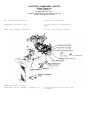
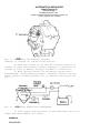
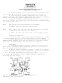
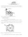
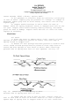
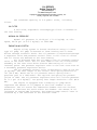
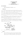
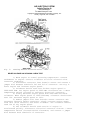
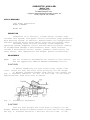
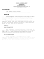
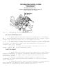
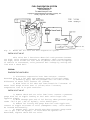
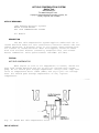
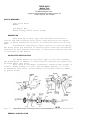
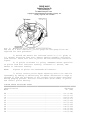
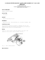
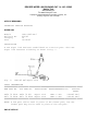
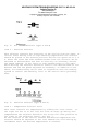
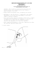
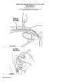
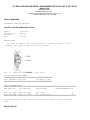
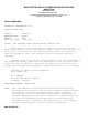
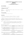
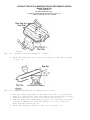
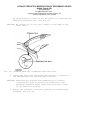
DESCRIPTION
Main switch is used to turn system on and off. A control
switch with "SET (ACCEL)" and "COAST (RESUME)" is used to set desired
speed. System will not operate at speeds under 25 MPH. Main switch is
located on the right side of dash. Control switch is on right side of
steering column.
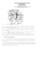
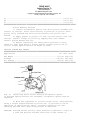
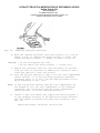
OPERATION
MAIN SWITCH
Pressing the main switch activates the cruise control.
CONTROL SWITCH
When "SET" switch is pressed and then released, desired speed
is set. If switch is continuously pressed, the vehicle will accelerate
until switch is released, at which time the new or higher speed will
be set.
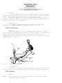
When "COAST" switch is moved down or rearward, speed will be
reduced. When switch is released, the new or lower speed will be set.
If cruise control is overridden by means other than the main switch,
original speed can be resumed by operating switch forward or up.
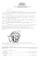
TROUBLE SHOOTING
CRUISE CONTROL SYSTEM DOES NOT WORK
Blown fuse. Faulty main switch, control switch, speed sensor
or actuator. Malfunction of stop, clutch or inhibitor switch. Bad
ground or wiring.
SPEED SETTING CAN'T BE CANCELED
Faulty control unit. Malfunction of clutch, stop or inhibitor
switch.
SET SPEED IS NOT HELD
Faulty actuator, control unit or speed sensor. Actuator
control cable malfunction.
SYSTEM DOESN'T ENGAGE IMMEDIATELY
CRUISE CONTROL SYSTEM
Article Text (p. 2)
1983 Mazda RX7
For www.iluvmyrx7.com
Copyright © 1998 Mitchell Repair Information Company, LLC
Sunday, August 26, 2001 03:28PM
Faulty actuator, control switch or unit. Actuator control
cable malfunction.
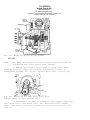
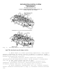
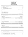
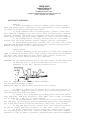
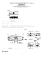
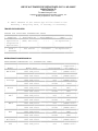
TESTING
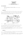
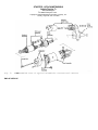
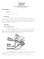
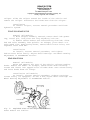
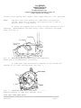
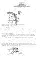
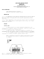
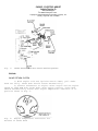
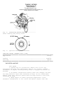
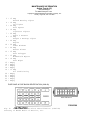
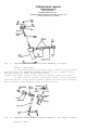
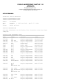
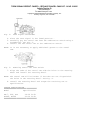
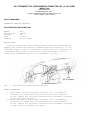
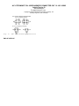
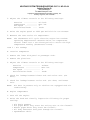
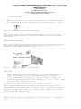
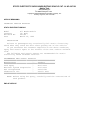
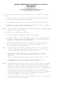
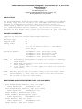
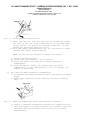
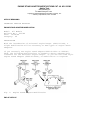
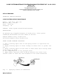
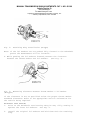
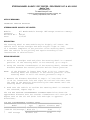
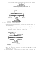
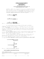
1) Support vehicle with drive wheels off of ground. Turn
ignition switch ON. With control unit connected, connect negative
probe of voltmeter to terminal M of control unit connector. Refer to
CRUISE CONTROL UNIT CONNECTOR DIAGRAM. Test terminals D through N. See
CRUISE CONTROL UNIT TESTING table. If values do not match those
specified, check appropriate circuits. If values do match those
specified, go to next step.
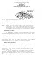
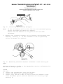
2) Start engine and switch cruise control main switch ON.
Increase speed until 30 MPH is indicated and push cruise control SET
button. Connect negative probe of voltmeter to terminal M of control
unit connector. Test terminals A through C. See
CRUISE CONTROL UNIT TESTING table. If values do not match those
specified, check appropriate circuits.
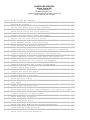
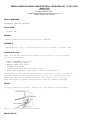
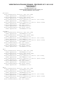
Cruise Control Unit Connector Diagram
ÚÄÄÄÂÄÄÄÂÄÄÄ¿
ÚÄÄÄÂÄÄÄÂÄÄÄ¿
³ M ³ K ³ I ³
³ E ³ C ³ A ³
ÃÄÄÄÅÄÄÄÅÄÄÄÅÄÄÄÅÄÄÄÅÄÄÄÅÄÄÄ´
³ N ³ L ³ J ³ H ³ F ³ D ³ B ³
ÀÄÄÄÁÄÄÄÁÄÄÄÁÄÄÄÁÄÄÄÁÄÄÄÁÄÄÄÙ
CRUISE CONTROL UNIT TESTING TABLE
ÚÄÄÄÄÄÄÄÄÄÄÂÄÄÄÄÄÄÄÄÄÄÄÄÄÄÄÄÄÄÄÄÄÄÄÄÄÄÄÄÂÄÄÄÄÄÄÄÄÄÄÄ¿
³ Terminal ³
Action
³ Voltage ³
ÃÄÄÄÄÄÄÄÄÄÄÅÄÄÄÄÄÄÄÄÄÄÄÄÄÄÄÄÄÄÄÄÄÄÄÄÄÄÄÄÅÄÄÄÄÄÄÄÄÄÄÄ´
³
F
³
At all times
³ 12 volts ³
ÃÄÄÄÄÄÄÄÄÄÄÅÄÄÄÄÄÄÄÄÄÄÄÄÄÄÄÄÄÄÄÄÄÄÄÄÄÄÄÄÅÄÄÄÄÄÄÄÄÄÄÄ´
³
I
³
Push SET button
³ 0 volts ³
³
ÃÄÄÄÄÄÄÄÄÄÄÄÄÄÄÄÄÄÄÄÄÄÄÄÄÄÄÄÄÅÄÄÄÄÄÄÄÄÄÄÄ´
³
³
Release SET button
³ 8 volts ³
ÃÄÄÄÄÄÄÄÄÄÄÅÄÄÄÄÄÄÄÄÄÄÄÄÄÄÄÄÄÄÄÄÄÄÄÄÄÄÄÄÅÄÄÄÄÄÄÄÄÄÄÄ´
³
J
³
Push COAST button
³ 0 volts ³
³
ÃÄÄÄÄÄÄÄÄÄÄÄÄÄÄÄÄÄÄÄÄÄÄÄÄÄÄÄÄÅÄÄÄÄÄÄÄÄÄÄÄ´
³
³
Release COAST button
³ 8 volts ³
ÃÄÄÄÄÄÄÄÄÄÄÅÄÄÄÄÄÄÄÄÄÄÄÄÄÄÄÄÄÄÄÄÄÄÄÄÄÄÄÄÅÄÄÄÄÄÄÄÄÄÄÄ´
³
K
³
Push RESUME button
³ 0 volts ³
³
ÃÄÄÄÄÄÄÄÄÄÄÄÄÄÄÄÄÄÄÄÄÄÄÄÄÄÄÄÄÅÄÄÄÄÄÄÄÄÄÄÄ´
³
³
Release RESUME button
³ 8 volts ³
ÃÄÄÄÄÄÄÄÄÄÄÅÄÄÄÄÄÄÄÄÄÄÄÄÄÄÄÄÄÄÄÄÄÄÄÄÄÄÄÄÅÄÄÄÄÄÄÄÄÄÄÄ´
³
E
³ Push brake or clutch pedal ³ 12 volts ³
ÃÄÄÄÄÄÄÄÄÄÄÅÄÄÄÄÄÄÄÄÄÄÄÄÄÄÄÄÄÄÄÄÄÄÄÄÄÄÄÄÅÄÄÄÄÄÄÄÄÄÄÄ´
³
N
³
Push brake pedal
³ 12 volts ³
ÃÄÄÄÄÄÄÄÄÄÄÅÄÄÄÄÄÄÄÄÄÄÄÄÄÄÄÄÄÄÄÄÄÄÄÄÄÄÄÄÅÄÄÄÄÄÄÄÄÄÄÄ´
³
D
³
Shift to P or N (1)
³ 0 volts ³
³
ÃÄÄÄÄÄÄÄÄÄÄÄÄÄÄÄÄÄÄÄÄÄÄÄÄÄÄÄÄÅÄÄÄÄÄÄÄÄÄÄÄ´
CRUISE CONTROL SYSTEM
Article Text (p. 3)
1983 Mazda RX7
For www.iluvmyrx7.com
Copyright © 1998 Mitchell Repair Information Company, LLC
Sunday, August 26, 2001 03:28PM
³
³
Shift to D or R (1)
³ 12 volts ³
ÃÄÄÄÄÄÄÄÄÄÄÅÄÄÄÄÄÄÄÄÄÄÄÄÄÄÄÄÄÄÄÄÄÄÄÄÄÄÄÄÅÄÄÄÄÄÄÄÄÄÄÄ´
³
B
³
Push SET button
³ 0 volts ³
³
ÃÄÄÄÄÄÄÄÄÄÄÄÄÄÄÄÄÄÄÄÄÄÄÄÄÄÄÄÄÅÄÄÄÄÄÄÄÄÄÄÄ´
³
³
Release SET button
³ 12 volts ³
ÃÄÄÄÄÄÄÄÄÄÄÅÄÄÄÄÄÄÄÄÄÄÄÄÄÄÄÄÄÄÄÄÄÄÄÄÄÄÄÄÅÄÄÄÄÄÄÄÄÄÄÄ´
³
A
³
Push COAST button
³ 0 volts ³
³
ÃÄÄÄÄÄÄÄÄÄÄÄÄÄÄÄÄÄÄÄÄÄÄÄÄÄÄÄÄÅÄÄÄÄÄÄÄÄÄÄÄ´
³
³
Release COAST button
³ 12 volts ³
ÃÄÄÄÄÄÄÄÄÄÄÅÄÄÄÄÄÄÄÄÄÄÄÄÄÄÄÄÄÄÄÄÄÄÄÄÄÄÄÄÅÄÄÄÄÄÄÄÄÄÄÄ´
³
C
³
Push clutch pedal
³ 0 volts ³
³
ÃÄÄÄÄÄÄÄÄÄÄÄÄÄÄÄÄÄÄÄÄÄÄÄÄÄÄÄÄÅÄÄÄÄÄÄÄÄÄÄÄ´
³
³
Release clutch pedal
³ 12 volts ³
ÃÄÄÄÄÄÄÄÄÄÄÅÄÄÄÄÄÄÄÄÄÄÄÄÄÄÄÄÄÄÄÄÄÄÄÄÄÄÄÄÅÄÄÄÄÄÄÄÄÄÄÄ´
H
³ * Engine OFF
³ 0-9 volts ³
³
³
³ * Remove speedometer cable ³
³
³
³
from transmission.
³
³
³
³ * Ignition ON
³
³
³
³ * Rotate cable by hand
³
³
ÃÄÄÄÄÄÄÄÄÄÄÁÄÄÄÄÄÄÄÄÄÄÄÄÄÄÄÄÄÄÄÄÄÄÄÄÄÄÄÄÁÄÄÄÄÄÄÄÄÄÄÄ´
³ (1) - Automatic transmission only.
³
ÀÄÄÄÄÄÄÄÄÄÄÄÄÄÄÄÄÄÄÄÄÄÄÄÄÄÄÄÄÄÄÄÄÄÄÄÄÄÄÄÄÄÄÄÄÄÄÄÄÄÄÄÙ
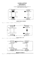
WIRING DIAGRAM
See WIRING DIAGRAMS article for cruise control circuit
diagram.
END OF ARTICLE
INSTRUMENT PANEL - STANDARD
Article Text
1983 Mazda RX7
For www.iluvmyrx7.com
Copyright © 1998 Mitchell Repair Information Company, LLC
Sunday, August 26, 2001 03:29PM
ARTICLE BEGINNING
Switches & Instrument Panels
MAZDA
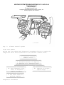
DESCRIPTION & OPERATION
All models have a steering column mounted combination switch
to control turn signals, headlights and wipers. The instrument
cluster contains a speedometer, fuel gauge and water temperature
gauge.
Some models also have a tachometer, voltmeter and oil
pressure gauge. The fuel and temperature gauges operate on 7 volts,
supplied by a cluster-mounted voltage regulator. The sending units
are variable-resistance type and have the same resistance values on
all models.
TESTING
GAUGES
1) Turn ignition on. If gauge needles do not move at all,
check for blown fuse or broken power wire. If both gauges are
inoperative, voltage regulator may be the cause. If only one gauge
does not work, the gauge, sending unit, or connecting wiring may be
at fault.
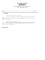
2) To test temperature gauge, disconnect sending unit wire.
Connect a resistor between wire and ground, then check gauge reading.
Change resistance and recheck. If gauge readings are as shown in
tables, replace sending unit. If not, repair wiring or replace gauge.
3) To test fuel gauge, disconnect wire to sending unit at
fuel tank (all except GLC Wagon) or unplug connector behind left kick
panel (GLC Wagon). Connect resistor between Yellow wire and ground.
Check gauge reading.
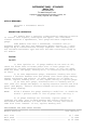
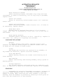
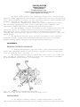
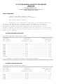
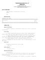
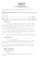
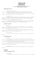
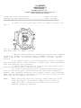
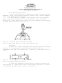
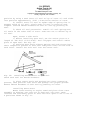
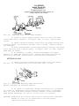
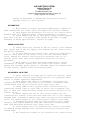
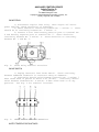
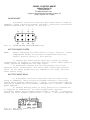
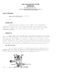
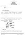
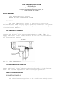
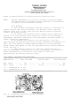
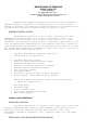
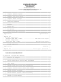
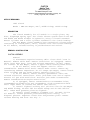
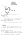
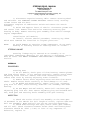
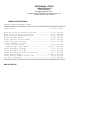
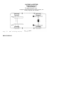
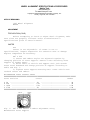
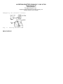
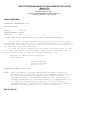
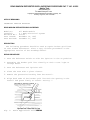
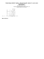
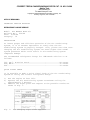
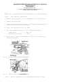
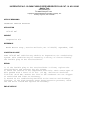
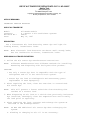
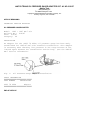
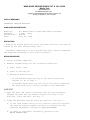
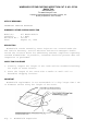
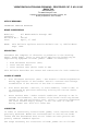
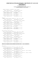
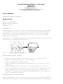
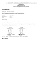
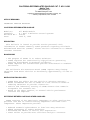
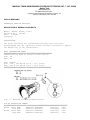
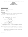
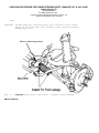
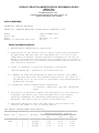
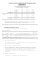
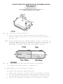
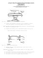
NOTE:
Allow 2 minutes for gauge reading to stabilize. It should be
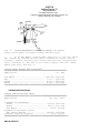
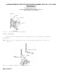
within 1 pointer width of line on gauge face. See Fig. 1.
4) If gauge readings are incorrect, replace gauge. If
readings are okay, test in-tank sending unit before replacing it.
Resistance should measure 0-5 ohms with float raised, and 103-117
ohms with float lowered. If not, replace sending unit.
RESISTANCES FOR FUEL GAUGE TESTING
ÄÄÄÄÄÄÄÄÄÄÄÄÄÄÄÄÄÄÄÄÄÄÄÄÄÄÄÄÄÄÄÄÄÄÄÄÄÄÄÄÄÄÄÄÄÄÄÄÄÄÄÄÄÄÄÄÄÄÄÄÄÄÄÄÄÄÄÄÄÄ
Needle Position
Test Resistor
Full Line ............................................... (1) 7 ohms
Half Tank .................................................. 33 ohms
Empty Line ............................................. (2) 95 ohms
INSTRUMENT PANEL - STANDARD
Article Text (p. 2)
1983 Mazda RX7
For www.iluvmyrx7.com
Copyright © 1998 Mitchell Repair Information Company, LLC
Sunday, August 26, 2001 03:29PM
(1) - On Pickup, 3 ohms.
(2) - On Pickup, 110 ohms.
ÄÄÄÄÄÄÄÄÄÄÄÄÄÄÄÄÄÄÄÄÄÄÄÄÄÄÄÄÄÄÄÄÄÄÄÄÄÄÄÄÄÄÄÄÄÄÄÄÄÄÄÄÄÄÄÄÄÄÄÄÄÄÄÄÄÄÄÄÄÄ
RESISTANCES FOR TEMPERATURE GAUGE TESTING
ÄÄÄÄÄÄÄÄÄÄÄÄÄÄÄÄÄÄÄÄÄÄÄÄÄÄÄÄÄÄÄÄÄÄÄÄÄÄÄÄÄÄÄÄÄÄÄÄÄÄÄÄÄÄÄÄÄÄÄÄÄÄÄÄÄÄÄÄÄÄ
Model
GLC Wagon & 626 ...........
RX7 .......................
GLC .......................
Cold Line
Hot Line
233 ohms ..................... 16 ohms
104 ohms ..................... 21 ohms
154 ohms ..................... 12 ohms
ÄÄÄÄÄÄÄÄÄÄÄÄÄÄÄÄÄÄÄÄÄÄÄÄÄÄÄÄÄÄÄÄÄÄÄÄÄÄÄÄÄÄÄÄÄÄÄÄÄÄÄÄÄÄÄÄÄÄÄÄÄÄÄÄÄÄÄÄÄÄ
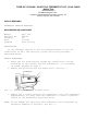
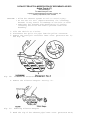
REMOVAL & INSTALLATION
INSTRUMENT CLUSTER
Removal (GLC Hatchback)
Disconnect battery ground. Remove steering wheel. Remove
meter hood by moving it up and down with hands. Disconnect
speedometer cable and remove 4 cluster screws. Pull cluster back and
unplug wiring.
Installation
To install, reverse removal procedure.
Removal (GLC Wagon)
1) Disconnect battery ground. Place a strip of masking tape
along edge of instrument panel under cluster to protect finish.
Remove 2 screws and meter hood.
2) Remove 1 screw at left end of center panel, then unsnap
panel. Remove 3 screws under edge of dashboard cover and remove
cover. Remove 3 cluster screws, disconnect speedometer cable and
wires and remove cluster.
Installation
To install, reverse removal procedure.
Removal (Pickups & 626)
Disconnect battery ground. Remove steering wheel and column
cover. Disconnect speedometer cable. Remove cluster hood and mounting
bolts. Pull cluster back, unplug wiring and remove cluster.
Installation
To install, reverse removal procedure.
Removal (RX7)
Disconnect battery ground. Remove steering wheel. Remove 2
screws and cluster cover. Remove cluster attaching screws. Disconnect
speedometer cable and pull cluster back. Unplug wiring and remove
cluster.
Installation
INSTRUMENT PANEL - STANDARD
Article Text (p. 3)
1983 Mazda RX7
For www.iluvmyrx7.com
Copyright © 1998 Mitchell Repair Information Company, LLC
Sunday, August 26, 2001 03:29PM
To install, reverse removal procedure.
COMBINATION SWITCH
Removal
Disconnect battery ground. Remove steering wheel. Remove
column covers and snap ring at top of column (if equipped). Unplug
wiring connectors. Loosen combination switch screw. Remove switch.
Installation
To install, reverse removal procedure.
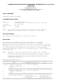
Fig. 1: Gauge Testing Needle Locations.
Needle should indicate proper reading when test resistor is connected.
END OF ARTICLE
WIPER/WASHER SYSTEM
Article Text
1983 Mazda RX7
For www.iluvmyrx7.com
Copyright © 1998 Mitchell Repair Information Company, LLC
Sunday, August 26, 2001 03:29PM
ARTICLE BEGINNING
1983 Wiper/Washer Systems
MAZDA
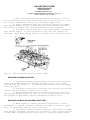
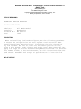
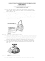
DESCRIPTION
All models have a 2-speed wiper motor with intermittent wipe
feature. GLC and RX7 models may be equipped with a rear window
wiper/washer system. The wiper switch for GLC Wagon is a lever on the
left side of the steering column.
On all other models wiper lever is on the right side of
column. A time delay relay is used to control the intermittent cycle
on all except RX7 models. On RX7, wipers are timed by the "Control
Processing Unit" that also operates a number of other accessories.
OPERATION
GLC WAGON
The wiper speeds are controlled by twisting the lever to the
left of the steering column. The washer is operated by pressing in on
the end of the lever. The rear wiper on GLC Wagon is turned on by
pulling out the dash-mounted switch, while the washer operates when
the switch is turned.
ALL OTHER MODELS
The wipers are controlled by a lever on the right side of
the steering column. As the lever is moved down, it switches the
wipers to intermittent, low speed and high speed. If the lever is
pulled toward the steering wheel, the washer sprays.
If the lever is pushed away from the steering wheel, the
wipers sweep until it is released. The rear wiper/washer on GLC
Hatchback is controlled by a rocker switch on the instrument panel.
The RX7 rear wiper switch is on the console.
TESTING
WIPER MOTOR
1) Remove wiper motor from vehicle. Connect jumper wires to
connector at motor to check both speeds. For low speed, connect
battery voltage to Blue wire terminal and ground the Blue/White
terminal. For high speed, ground the Blue/Red terminal instead.
2) To check the park switch, apply battery voltage to the
Blue wire terminal. Connect a jumper wire between Blue/White and
Blue/Black. Ground the Black wire. Motor should run briefly and stop.
MAZDA INTERMITTENT WIPER RELAY LOCATIONS
ÄÄÄÄÄÄÄÄÄÄÄÄÄÄÄÄÄÄÄÄÄÄÄÄÄÄÄÄÄÄÄÄÄÄÄÄÄÄÄÄÄÄÄÄÄÄÄÄÄÄÄÄÄÄÄÄÄÄÄÄÄÄÄÄÄÄÄÄÄÄ
WIPER/WASHER SYSTEM
Article Text (p. 2)
1983 Mazda RX7
For www.iluvmyrx7.com
Copyright © 1998 Mitchell Repair Information Company, LLC
Sunday, August 26, 2001 03:29PM
Model
Connector
Location
GLC
Hatchback ................. 6-pin ... Left of instrument cluster
Wagon ..................... 6-pin ... Left of instrument cluster
B2000 &
B2200 ..................... 4-pin ... Left of instrument cluster
RX7 (1) ................... 17-pin .............. Left kick panel
626 ....................... 6-pin (2) . Left of instrument cluster
(1) - Time delay is controlled by "Control Processing Unit".
(2) - For 4-door models. On 2-door and 5-door models, relay has
9-pins.
ÄÄÄÄÄÄÄÄÄÄÄÄÄÄÄÄÄÄÄÄÄÄÄÄÄÄÄÄÄÄÄÄÄÄÄÄÄÄÄÄÄÄÄÄÄÄÄÄÄÄÄÄÄÄÄÄÄÄÄÄÄÄÄÄÄÄÄÄÄÄ
3) To check rear wiper motor, apply battery voltage to
Blue/Red wire and ground the Blue/White wire. Motor should run
steadily.
REMOVAL & INSTALLATION
FRONT WIPER MOTOR ASSEMBLY
Removal
1) Run wipers until they are in vertical position, then turn
ignition off or disconnect battery cable. Remove wiper arms and shaft
nuts.
2) Remove cowl grille or access panel. Unplug at motor.
Remove mounting bolts and wiper motor.
Installation
To install, reverse removal procedure.
REAR WIPER MOTOR ASSEMBLY
Removal
Disconnect battery ground. Remove wiper arm and shaft nuts.
Remove trim on rear hatch. Remove fasteners and remove wiper hole
cover. Disconnect wiring, remove attaching bolts and remove rear
wiper motor.
Installation
To install, reverse removal procedure.
WIPER SWITCH
Removal
Disconnect battery ground. Remove steering wheel. Remove
column covers and snap ring at top of column (if equipped). Unplug
wiring connectors. Loosen combination switch screw. Remove
combination switch.
WIPER/WASHER SYSTEM
Article Text (p. 3)
1983 Mazda RX7
For www.iluvmyrx7.com
Copyright © 1998 Mitchell Repair Information Company, LLC
Sunday, August 26, 2001 03:29PM
Installation
To install, reverse removal procedure.
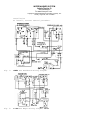
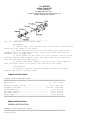
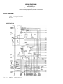
Fig. 1:
Mazda GLC Hatchback Wiring Diagram
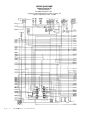
Fig. 2:
Mazda GLC Wagon Wiring Diagram
WIPER/WASHER SYSTEM
Article Text (p. 4)
1983 Mazda RX7
For www.iluvmyrx7.com
Copyright © 1998 Mitchell Repair Information Company, LLC
Sunday, August 26, 2001 03:29PM
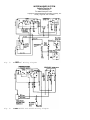
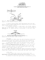
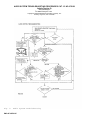
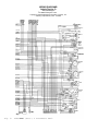
Fig. 3:
Mazda RX7 Wiring Diagram
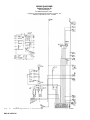
Fig. 4:
Mazda B2000 and B2200 Wiring Diagram
WIPER/WASHER SYSTEM
Article Text (p. 5)
1983 Mazda RX7
For www.iluvmyrx7.com
Copyright © 1998 Mitchell Repair Information Company, LLC
Sunday, August 26, 2001 03:29PM
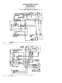
Fig. 5: Mazda 626 Front Wiper Wiring Diagram
(4-Door Models)
Fig. 6: Mazda 626 Front Wiper Wiring Diagram
(2 & 5-Door Models)
WIPER/WASHER SYSTEM
Article Text (p. 6)
1983 Mazda RX7
For www.iluvmyrx7.com
Copyright © 1998 Mitchell Repair Information Company, LLC
Sunday, August 26, 2001 03:29PM
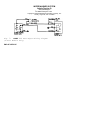
Fig. 7: Mazda 626 Rear Wiper Wiring Diagram
(4-Door Models Only)
END OF ARTICLE
ELECTRICAL COMPONENT LOCATOR
Article Text
1983 Mazda RX7
For www.iluvmyrx7.com
Copyright © 1998 Mitchell Repair Information Company, LLC
Sunday, August 26, 2001 03:29PM
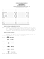
ARTICLE BEGINNING
1983 Mazda
RX7 ELECTRICAL COMPONENTS
RX7 COMPONENT LOCATOR CHART
ÄÄÄÄÄÄÄÄÄÄÄÄÄÄÄÄÄÄÄÄÄÄÄÄÄÄÄÄÄÄÄÄÄÄÄÄÄÄÄÄÄÄÄÄÄÄÄÄÄÄÄÄÄÄÄÄÄÄÄÄÄÄÄÄÄÄÄÄÄÄ
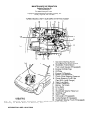
MISCELLANEOUS COMPONENTS
ÄÄÄÄÄÄÄÄÄÄÄÄÄÄÄÄÄÄÄÄÄÄÄÄÄÄÄÄÄÄÄÄÄÄÄÄÄÄÄÄÄÄÄÄÄÄÄÄÄÄÄÄÄÄÄÄÄÄÄÄÄÄÄÄÄÄÄÄÄÄ
Component
Component Location
ÄÄÄÄÄÄÄÄÄÄÄÄÄÄÄÄÄÄÄÄÄÄÄÄÄÄÄÄÄÄÄÄÄÄÄÄÄÄÄÄÄÄÄÄÄÄÄÄÄÄÄÄÄÄÄÄÄÄÄÄÄÄÄÄÄÄÄÄÄÄ
A/C-Heater Blower Motor Resistor
On blower housing under right
side of dash.
Choke Magnet
In choke switch under dash.
ELECTRICAL COMPONENT LOCATOR
Article Text (p. 2)
1983 Mazda RX7
For www.iluvmyrx7.com
Copyright © 1998 Mitchell Repair Information Company, LLC
Sunday, August 26, 2001 03:29PM
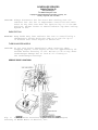
Cruise Control Servo
On right inner fender panel.
Fuse Block
Below left side of dash.
Fusible Links
On left shock tower.
Seat Belt Warning Chime
Behind right side of
instrument cluster.
CONTROL UNITS
ÄÄÄÄÄÄÄÄÄÄÄÄÄÄÄÄÄÄÄÄÄÄÄÄÄÄÄÄÄÄÄÄÄÄÄÄÄÄÄÄÄÄÄÄÄÄÄÄÄÄÄÄÄÄÄÄÄÄÄÄÄÄÄÄÄÄÄÄÄÄ
Component
Component Location
ÄÄÄÄÄÄÄÄÄÄÄÄÄÄÄÄÄÄÄÄÄÄÄÄÄÄÄÄÄÄÄÄÄÄÄÄÄÄÄÄÄÄÄÄÄÄÄÄÄÄÄÄÄÄÄÄÄÄÄÄÄÄÄÄÄÄÄÄÄÄ
ELECTRICAL COMPONENT LOCATOR
Article Text (p. 3)
1983 Mazda RX7
For www.iluvmyrx7.com
Copyright © 1998 Mitchell Repair Information Company, LLC
Sunday, August 26, 2001 03:29PM
Coolant Level Control Unit
On left kick panel.
Control Processing Unit
On left kick panel.
Cruise Control Unit
At left side of luggage
ELECTRICAL COMPONENT LOCATOR
Article Text (p. 4)
1983 Mazda RX7
For www.iluvmyrx7.com
Copyright © 1998 Mitchell Repair Information Company, LLC
Sunday, August 26, 2001 03:29PM
compartment.
Emission Control Unit
Below left side of dash.
Oscillator Control Unit
At left front corner of engine
compartment.
ELECTRICAL COMPONENT LOCATOR
Article Text (p. 5)
1983 Mazda RX7
For www.iluvmyrx7.com
Copyright © 1998 Mitchell Repair Information Company, LLC
Sunday, August 26, 2001 03:29PM
Stop Light Checker
On left kick panel.
RELAYS
ÄÄÄÄÄÄÄÄÄÄÄÄÄÄÄÄÄÄÄÄÄÄÄÄÄÄÄÄÄÄÄÄÄÄÄÄÄÄÄÄÄÄÄÄÄÄÄÄÄÄÄÄÄÄÄÄÄÄÄÄÄÄÄÄÄÄÄÄÄÄ
Component
Component Location
ÄÄÄÄÄÄÄÄÄÄÄÄÄÄÄÄÄÄÄÄÄÄÄÄÄÄÄÄÄÄÄÄÄÄÄÄÄÄÄÄÄÄÄÄÄÄÄÄÄÄÄÄÄÄÄÄÄÄÄÄÄÄÄÄÄÄÄÄÄÄ
A/C Relays (2)
In left rear corner of engine
compartment.
ELECTRICAL COMPONENT LOCATOR
Article Text (p. 6)
1983 Mazda RX7
For www.iluvmyrx7.com
Copyright © 1998 Mitchell Repair Information Company, LLC
Sunday, August 26, 2001 03:29PM
Choke & Check Relay
In left rear corner of engine
compartment.
Horn Relay
At left kick panel.
ELECTRICAL COMPONENT LOCATOR
Article Text (p. 7)
1983 Mazda RX7
For www.iluvmyrx7.com
Copyright © 1998 Mitchell Repair Information Company, LLC
Sunday, August 26, 2001 03:29PM
Hot Start Relay
In left rear corner of engine
compartment.
Power Antenna Relay
Under left side of dash.
MOTORS
ELECTRICAL COMPONENT LOCATOR
Article Text (p. 8)
1983 Mazda RX7
For www.iluvmyrx7.com
Copyright © 1998 Mitchell Repair Information Company, LLC
Sunday, August 26, 2001 03:29PM
ÄÄÄÄÄÄÄÄÄÄÄÄÄÄÄÄÄÄÄÄÄÄÄÄÄÄÄÄÄÄÄÄÄÄÄÄÄÄÄÄÄÄÄÄÄÄÄÄÄÄÄÄÄÄÄÄÄÄÄÄÄÄÄÄÄÄÄÄÄÄ
Component
Component Location
ÄÄÄÄÄÄÄÄÄÄÄÄÄÄÄÄÄÄÄÄÄÄÄÄÄÄÄÄÄÄÄÄÄÄÄÄÄÄÄÄÄÄÄÄÄÄÄÄÄÄÄÄÄÄÄÄÄÄÄÄÄÄÄÄÄÄÄÄÄÄ
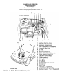
A/C-Heater Blower Motor
Under dash in heater box.
Front Washer Motor
On reservoir in center right
side of engine compartment.
Front Wiper Motor
Under left side of cowl.
Fuel Pump
Near fuel tank on frame
member.
Headlight Washer Motor
In right front corner of
engine compartment.
Hot Start Assist Motor
In left rear corner of engine
compartment.
Headlight Retractor Motors
Behind each headlight
assembly.
Power Antenna Motor
In right rear corner of
luggage compartment.
Power Window Motors
One in each door.
Rear Washer Motor
In left rear quarter panel.
Rear Wiper Motor
On bottom right side of rear
hatch.
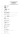
SENDING UNITS/SENSORS
ÄÄÄÄÄÄÄÄÄÄÄÄÄÄÄÄÄÄÄÄÄÄÄÄÄÄÄÄÄÄÄÄÄÄÄÄÄÄÄÄÄÄÄÄÄÄÄÄÄÄÄÄÄÄÄÄÄÄÄÄÄÄÄÄÄÄÄÄÄÄ
ELECTRICAL COMPONENT LOCATOR
Article Text (p. 9)
1983 Mazda RX7
For www.iluvmyrx7.com
Copyright © 1998 Mitchell Repair Information Company, LLC
Sunday, August 26, 2001 03:29PM
Component
Component Location
ÄÄÄÄÄÄÄÄÄÄÄÄÄÄÄÄÄÄÄÄÄÄÄÄÄÄÄÄÄÄÄÄÄÄÄÄÄÄÄÄÄÄÄÄÄÄÄÄÄÄÄÄÄÄÄÄÄÄÄÄÄÄÄÄÄÄÄÄÄÄ
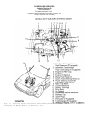
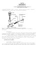
Brake Fluid Level Sensor
In brake master cylinder.
Coolant Level Sensor
On top of radiator.
Cooling Fan Temperature Sensor
In lower left side of
radiator.
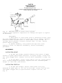
Cruise Control Sensor
On back of speedometer
Fuel Gauge Sending Unit
On left side of fuel tank.
ELECTRICAL COMPONENT LOCATOR
Article Text (p. 10)
1983 Mazda RX7
For www.iluvmyrx7.com
Copyright © 1998 Mitchell Repair Information Company, LLC
Sunday, August 26, 2001 03:30PM
Heat Hazard Sensor
Under right side floor mat.
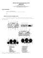
Oil Level Sensor, (Graphic 1)
In left side of oil pan.
ELECTRICAL COMPONENT LOCATOR
Article Text (p. 11)
1983 Mazda RX7
For www.iluvmyrx7.com
Copyright © 1998 Mitchell Repair Information Company, LLC
Sunday, August 26, 2001 03:30PM
Oil Level Sensor, (Graphic 2)
In left side of oil pan.
Oil Pressure Sending Unit
On rear left side of block
below oil filter.
ELECTRICAL COMPONENT LOCATOR
Article Text (p. 12)
1983 Mazda RX7
For www.iluvmyrx7.com
Copyright © 1998 Mitchell Repair Information Company, LLC
Sunday, August 26, 2001 03:30PM
Oil Thermo Sensor (Fed.),
(Graphic 1)
In left side of oil pan.
Oil Thermo Sensor (Fed.),
(Graphic 2)
In left side of oil pan.
Throttle Sensor
On carburetor throttle
linkage.
Washer Fluid Level Sensor
On bottom of washer fluid
reservoir.
ELECTRICAL COMPONENT LOCATOR
Article Text (p. 13)
1983 Mazda RX7
For www.iluvmyrx7.com
Copyright © 1998 Mitchell Repair Information Company, LLC
Sunday, August 26, 2001 03:30PM
SOLENOIDS/SOLENOID VALVES
ÄÄÄÄÄÄÄÄÄÄÄÄÄÄÄÄÄÄÄÄÄÄÄÄÄÄÄÄÄÄÄÄÄÄÄÄÄÄÄÄÄÄÄÄÄÄÄÄÄÄÄÄÄÄÄÄÄÄÄÄÄÄÄÄÄÄÄÄÄÄ
Component
Component Location
ÄÄÄÄÄÄÄÄÄÄÄÄÄÄÄÄÄÄÄÄÄÄÄÄÄÄÄÄÄÄÄÄÄÄÄÄÄÄÄÄÄÄÄÄÄÄÄÄÄÄÄÄÄÄÄÄÄÄÄÄÄÄÄÄÄÄÄÄÄÄ
A/C Solenoid Valve (White),
(Graphic 1)
A/C Solenoid Valve (White),
(Graphic 2)
In solenoid block on left side
of engine.
In solenoid block on left side
of engine.
ELECTRICAL COMPONENT LOCATOR
Article Text (p. 14)
1983 Mazda RX7
For www.iluvmyrx7.com
Copyright © 1998 Mitchell Repair Information Company, LLC
Sunday, August 26, 2001 03:30PM
Air Vent Solenoid Valve
On side of carburetor.
Downshift Solenoid (A/T)
On left side of transmission
case.
Fuel Door Release Solenoid
In left rear quarter panel.
Leading Vacuum Control
Solenoid, Valve (Brown), (Graphic 1)
In solenoid block on left side
of engine.
ELECTRICAL COMPONENT LOCATOR
Article Text (p. 15)
1983 Mazda RX7
For www.iluvmyrx7.com
Copyright © 1998 Mitchell Repair Information Company, LLC
Sunday, August 26, 2001 03:30PM
Leading Vacuum Control
Solenoid, Valve (Brown), (Graphic 2)
Rear Hatch Release Solenoid
Relief Solenoid Valve (Blue),
(Graphic 1)
In solenoid block on left side
of engine.
In center of rear finish
panel.
In solenoid block on left side
of engine.
ELECTRICAL COMPONENT LOCATOR
Article Text (p. 16)
1983 Mazda RX7
For www.iluvmyrx7.com
Copyright © 1998 Mitchell Repair Information Company, LLC
Sunday, August 26, 2001 03:30PM
Relief Solenoid Valve (Blue),
(Graphic 2)
Shutter Solenoid Valve (Yellow),
(Graphic 1)
In solenoid block on left side
of engine.
In solenoid block on left side
of engine.
ELECTRICAL COMPONENT LOCATOR
Article Text (p. 17)
1983 Mazda RX7
For www.iluvmyrx7.com
Copyright © 1998 Mitchell Repair Information Company, LLC
Sunday, August 26, 2001 03:30PM
Shutter Solenoid Valve (Yellow),
(Graphic 2)
Switching Solenoid Valve (Gray),
(Graphic 1)
In solenoid block on left side
of engine.
In solenoid block on left side
of engine.
ELECTRICAL COMPONENT LOCATOR
Article Text (p. 18)
1983 Mazda RX7
For www.iluvmyrx7.com
Copyright © 1998 Mitchell Repair Information Company, LLC
Sunday, August 26, 2001 03:30PM
Switching Solenoid Valve (Gray),
(Graphic 2)
Trailing Vacuum Control Solenoid,
(Graphic 1)
In solenoid block on left side
of engine.
In solenoid block on left side
of engine.
ELECTRICAL COMPONENT LOCATOR
Article Text (p. 19)
1983 Mazda RX7
For www.iluvmyrx7.com
Copyright © 1998 Mitchell Repair Information Company, LLC
Sunday, August 26, 2001 03:30PM
Trailing Vacuum Control Solenoid,
(Graphic 2)
In solenoid block on left side
of engine.
SWITCHES
ÄÄÄÄÄÄÄÄÄÄÄÄÄÄÄÄÄÄÄÄÄÄÄÄÄÄÄÄÄÄÄÄÄÄÄÄÄÄÄÄÄÄÄÄÄÄÄÄÄÄÄÄÄÄÄÄÄÄÄÄÄÄÄÄÄÄÄÄÄÄ
Component
Component Location
ÄÄÄÄÄÄÄÄÄÄÄÄÄÄÄÄÄÄÄÄÄÄÄÄÄÄÄÄÄÄÄÄÄÄÄÄÄÄÄÄÄÄÄÄÄÄÄÄÄÄÄÄÄÄÄÄÄÄÄÄÄÄÄÄÄÄÄÄÄÄ
A/C Low Pressure Switch
Below right side of dash.
Back-Up Light Switch (M/T)
On left side of transmission
case.
ELECTRICAL COMPONENT LOCATOR
Article Text (p. 20)
1983 Mazda RX7
For www.iluvmyrx7.com
Copyright © 1998 Mitchell Repair Information Company, LLC
Sunday, August 26, 2001 03:30PM
Brake/Stop Light Switch
On top of brake pedal bracket.
Clutch Switch
On top of clutch pedal
bracket.
ELECTRICAL COMPONENT LOCATOR
Article Text (p. 21)
1983 Mazda RX7
For www.iluvmyrx7.com
Copyright © 1998 Mitchell Repair Information Company, LLC
Sunday, August 26, 2001 03:30PM
Coolant Temperature Switch
At water pump.
Inhibitor Switch (A/T)
On left side of transmission
case.
Kickdown Switch
On accelerator pedal bracket.
Parking Brake Switch
On bottom of parking brake
lever.
END OF ARTICLE
ALTERNATOR & REGULATOR
Article Text
1983 Mazda RX7
For www.iluvmyrx7.com
Copyright © 1998 Mitchell Repair Information Company, LLC
Sunday, August 26, 2001 03:30PM
ARTICLE BEGINNING
1983 Alternators & Regulators
MITSUBISHI ALTERNATORS WITH INTEGRAL REGULATORS
Mazda
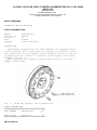
DESCRIPTION
Mitsubishi alternators are conventional 3-phase, selfrectifying type units containing 6 diodes (3 positive and 3
negative) which are used to rectify current. A case-mounted
Integrated Circuit (IC) regulator is used on all models.
APPLICATION
ÄÄÄÄÄÄÄÄÄÄÄÄÄÄÄÄÄÄÄÄÄÄÄÄÄÄÄÄÄÄÄÄÄÄÄÄÄÄÄÄÄÄÄÄÄÄÄÄÄÄÄÄÄÄÄÄÄÄÄÄÄÄÄÄÄÄÄÄÄÄ
Model
Volt/Amps
Part No.
Mazda
B2000 .................... 13.5/50 .................. A00IT23370
B2200 .................... 13.5/40 .................. A00IT23479
GLC
FWD ...................... 12/50 ............... (1) E56318300A
RWD ...................... 14/30 ............... (1) D50116300R
RX7 ....................... 12/50 ................ (1) N22118300
626 ....................... 12/60 ............... (1) FE0118300R
(1) - Vehicle manufacturer's part number.
ÄÄÄÄÄÄÄÄÄÄÄÄÄÄÄÄÄÄÄÄÄÄÄÄÄÄÄÄÄÄÄÄÄÄÄÄÄÄÄÄÄÄÄÄÄÄÄÄÄÄÄÄÄÄÄÄÄÄÄÄÄÄÄÄÄÄÄÄÄÄ
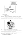
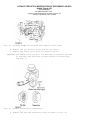
TESTING
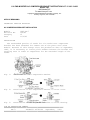
ON-VEHICLE TEST
CAUTION: DO NOT short across any alternator terminals or run vehicle
with any wires disconnected. Battery must be fully charged
for tests to be accurate.
Output Test
1) With ignition switch off, check voltage at "R" terminal
and "L" terminal. Reading at both terminals should be 0 volts. If not
0 volts, alternator is defective.
2) Turn ignition switch on but do not start engine. Voltage
at "L" should be 1-3 volts. If voltage is 0, alternator and regulator
are defective.
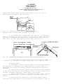
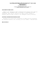
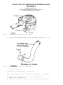
3) If voltage at "L" is close to battery voltage with
ignition on, short circuit the "F" terminal to rear alternator
housing. See Fig. 1.
ALTERNATOR & REGULATOR
Article Text (p. 2)
1983 Mazda RX7
For www.iluvmyrx7.com
Copyright © 1998 Mitchell Repair Information Company, LLC
Sunday, August 26, 2001 03:30PM
Fig. 1: Alternator "F" Terminal Location
Terminal is located .8" (20 mm) below the hole.
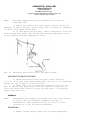
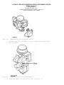
4) Read the voltage at "L" with "F" terminal shorted. If
voltage is lower than battery voltage, regulator is defective. If
voltage is close to battery voltage, alternator is defective.
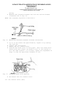
5) With ignition switch off and battery ground cable
disconnected, connect ammeter between alternator terminal "B" and
cable. Connect voltmeter between "B" (+) terminal and ground. See
Fig. 2.
Fig. 2:
Alternator Output Test Arrangement
6) Start engine and accelerate to 2000-3000 RPM. Turn on all
lights and check ammeter for output.
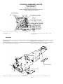
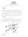
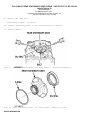
OVERHAUL
DISASSEMBLY
ALTERNATOR & REGULATOR
Article Text (p. 3)
1983 Mazda RX7
For www.iluvmyrx7.com
Copyright © 1998 Mitchell Repair Information Company, LLC
Sunday, August 26, 2001 03:30PM
1) After removing through bolts, insert screwdriver between
front housing and stator to separate.
2) Hold the rotor in a soft jawed vice. Remove pulley nut,
pulley, fan, and spacer. Remove rotor drive end housing by lightly
tapping end housing with a soft mallet.
3) To separate stator from diode end housing, unsolder three
negative diode leads and connections between diodes. Hold the stator
lead with a needle nose plier to prevent rectifier from overheating.
4) Remove condenser from the "B" terminal. Unsolder the "L"
and "B" terminal from the rectifier assembly. Lift out rectifier
assembly and brush holder.
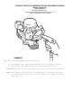
TESTING
Diode Assemblies
1) Check each diode with ohmmeter in forward and reverse
direction. If the diode shows large resistance in one direction and
small resistance in other direction, diode is normal.
2) If diode shows small resistance in both directions, it is
shorted. If large resistance is shown in both directions, diode is
open. Heat sink and diodes are replaced as an assembly.
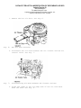
Fig. 3: Testing Mitsubishi Integral Regulator
Ensure variable resistor is set to middle of resistance range.
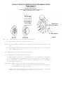
Rotor Field Continuity
Check continuity across field coil slip rings. A reading of
3-4 ohms must be obtained. No continuity, replace rotor.
ALTERNATOR & REGULATOR
Article Text (p. 4)
1983 Mazda RX7
For www.iluvmyrx7.com
Copyright © 1998 Mitchell Repair Information Company, LLC
Sunday, August 26, 2001 03:30PM
Rotor Field Coil Ground
Check continuity between individual slip rings and rotor
core/shaft. If there is continuity, coil or slip ring is grounded,
replace rotor.
Stator Coil Ground
Ensure no continuity exists between stator coil leads and
stator core.
Stator Coil Continuity
Check continuity between leads of stator coil. If there is
no continuity, replace stator.
Brush Wear Limit
Brushes must be replaced when worn to 1/3 of original
length. This limit is indicated by a wear limit line on the side of
each brush.
Brush Spring Pressure
Standard tension should be 12-16 oz. (340-453 g). Replace if
less than 7 oz. (198 g) or if springs are corroded.
COMPONENT REPLACEMENT
Brushes
To remove brushes from holder, unsolder pigtail from
terminal. To replace, solder pigtail to terminal ensure that 1/4"
of brush will be located in brush holder.
Diodes
The diodes and rectifier are serviced as an assembly. If
any diodes are defective, replace rectifier assembly.
Drive End Bearing
Remove bearing retainer set screws. Press bearing out of
front housing.
Rear Bearing
Remove rear bearing from housing assembly using a press or
bearing puller.
Voltage Regulator
The voltage regulator and brush holder are combined in one
unit. If regulator is found to be defective, replace as an assembly.
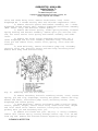
REASSEMBLY
Reassemble by reversing disassembly procedures. Soldering of
rectifier leads should be done in less than 5 seconds to prevent
damage to diodes. When installing the rotor assembly in the rear
housing, hold the brushes in position by inserting a stiff piece of
wire into the access hole in rear housing.
ALTERNATOR & REGULATOR
Article Text (p. 5)
1983 Mazda RX7
For www.iluvmyrx7.com
Copyright © 1998 Mitchell Repair Information Company, LLC
Sunday, August 26, 2001 03:30PM
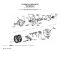
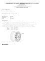
Fig. 4:
Exploded View of Mitsubishi Alternator
END OF ARTICLE
FUSE & FLASHER LOCATIONS
Article Text
1983 Mazda RX7
For www.iluvmyrx7.com
Copyright © 1998 Mitchell Repair Information Company, LLC
Sunday, August 26, 2001 03:30PM
ARTICLE BEGINNING
1983 Fuse Blocks, Flashers & Relays
MAZDA
Fig. 1:
Fuses & Flasher Locations
FUSES & FLASHER LOCATIONS
ÄÄÄÄÄÄÄÄÄÄÄÄÄÄÄÄÄÄÄÄÄÄÄÄÄÄÄÄÄÄÄÄÄÄÄÄÄÄÄÄÄÄÄÄÄÄÄÄÄÄÄÄÄÄÄÄÄÄÄÄÄÄÄÄÄÄÄÄÄÄ
Manufacturer & Models
Component Location in Fig. 1:
Mazda
B2000 & B2200 Pickups
Fuse Locations ...............................................
Flasher Locations ............................................
Relay Locations
Check & Choke ...............................................
Glow Plug ...................................................
Horn, A/C ...................................................
Wipers ......................................................
GLC Hatchback
Fuse Locations ...............................................
Flasher Locations ............................................
Relay Locations
Choke, A/C; Horn ............................................
Wipers, Others ..............................................
GLC Wagon
Fuse Locations ...............................................
Flasher Locations ............................................
Relay Locations
Check .......................................................
Horn ........................................................
Wipers ......................................................
RX7
(7)
(9)
(4)
(7)
(6)
(9)
(9)
(9)
(6)
(9)
(9)
(9)
(6)
(5)
(9)
FUSE & FLASHER LOCATIONS
Article Text (p. 2)
1983 Mazda RX7
For www.iluvmyrx7.com
Copyright © 1998 Mitchell Repair Information Company, LLC
Sunday, August 26, 2001 03:30PM
Fuse Locations ...............................................
Flasher Locations..............................................
Relay Locations
Check & Choke, Hot Start, A/C ...............................
Horn, Antenna ...............................................
626
Fuse Locations ................................................
Flasher Locations .............................................
Relay Locations
Wipers, Horn .................................................
(9)
(8)
(7)
(9)
(9)
(9)
(9)
ÄÄÄÄÄÄÄÄÄÄÄÄÄÄÄÄÄÄÄÄÄÄÄÄÄÄÄÄÄÄÄÄÄÄÄÄÄÄÄÄÄÄÄÄÄÄÄÄÄÄÄÄÄÄÄÄÄÄÄÄÄÄÄÄÄÄÄÄÄÄ
END OF ARTICLE
FUSES & CIRCUIT BREAKERS
Article Text
1983 Mazda RX7
For www.iluvmyrx7.com
Copyright © 1998 Mitchell Repair Information Company, LLC
Sunday, August 26, 2001 03:31PM
ARTICLE BEGINNING
Fuses & Circuit Breakers
1983-85 Mazda
RX7
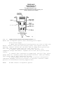
FUSES & CIRCUIT BREAKERS
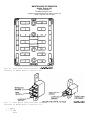
FUSE PANEL LOCATION
The main fuse block is located at the right rear side of the
engine compartment and contains high amperage fuses which protect
multiple circuits. Fuse box located above driver's left knee,
accessible through a removable cover, contains fuses for individual
circuits.
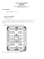
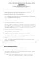
FUSE PANEL & FUSE BLOCK IDENTIFICATION (1983-85)
Fig. 1: Fuse Panel Identification (1983-85)
Courtesy of Mazda Motor of America Inc.
FUSES & CIRCUIT BREAKERS
Article Text (p. 2)
1983 Mazda RX7
For www.iluvmyrx7.com
Copyright © 1998 Mitchell Repair Information Company, LLC
Sunday, August 26, 2001 03:31PM
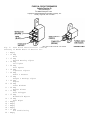
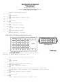
Fig. 2: Fuse Block Identification (1983-85)
Courtesy of Mazda Motor of America Inc.
1 - Empty
2 - 15 Amp
Horn
3 - 15 Amp
Hazard Warning Lights
4 - 10 Amp
Taillights
5 - 20 Amp
Roof Opener
6 - 10 Amp
Cigarette Lighter
7 - 20 Amp
Radio & Antenna
8 - 15 Amp
Gauges & Back-Up Lights
9 - 20 Amp
Engine
10 - 30 Amp
Power Windows
11 - 20 Amp
Heater Blower
12 - 15 Amp
Rear Defogger
13 - 15 Amp
Windshield Wipers
14 - 10 Amp
Rear Wiper
15 - Empty
16 - Empty
17 - Empty
18 - Empty
19 - 15 Amp
Air Conditioning
20 - Empty
FUSES & CIRCUIT BREAKERS
Article Text (p. 3)
1983 Mazda RX7
For www.iluvmyrx7.com
Copyright © 1998 Mitchell Repair Information Company, LLC
Sunday, August 26, 2001 03:31PM
21
22
23
24
-
Empty
Empty
Empty
Empty
CAUTIONS & WARNINGS
BRAKE PAD WEAR INDICATOR
Indicator will cause a squealing or scraping noise warning
that the pads need replacement.
HEADLIGHT RETRACTOR
Never operate headlight retractor when a person's hands, or
other objects are on or near the headlights. When working on the
headlights always remove the headlight retractor fuse.
AIR BAG SYSTEM
Always remove air bag system fuse when working on any
controls associated with the steering wheel or steering column.
END OF ARTICLE
IGNITION SYSTEM
Article Text
1983 Mazda RX7
For www.iluvmyrx7.com
Copyright © 1998 Mitchell Repair Information Company, LLC
Sunday, August 26, 2001 03:31PM
ARTICLE BEGINNING
1983 Distributors & Ignition Systems
MITSUBISHI ELECTRONIC IGNITION - MAZDA ROTARY ENGINE
Mazda RX7
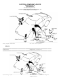
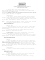
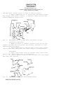
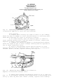
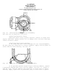
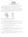
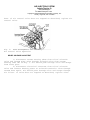
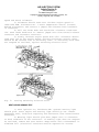
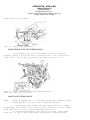
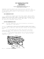
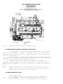
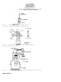
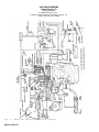
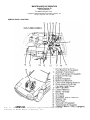
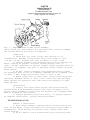
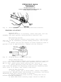
DESCRIPTION
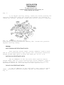
The Mitsubishi electronic ignition system, used on the Mazda
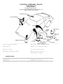
RX7 rotary engine, is unique in that it has 2 sets of spark plugs
(leading and trailing). There is one set in the front rotor housing
and one in the rear rotor housing. See Fig. 1. There are also 2
ignition coils, 2 pick-up coils located in the distributor, and 2
coil-to-distributor high tension wires.
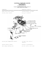
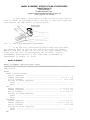
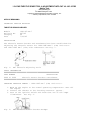
Fig. 1:
Schematic of RX7 Ignition System
There are 2 separate igniters, mounted externally on the
distributor housing. One is for the leading side and the other for
the trailing side. Other system components include a battery,
ignition switch, ignition control switches, (water temperature,
altitude, etc.), and various relays.
All models are equipped with an ignition control system and
centrifugal advance mechanisms. All models have vacuum control units
for both leading and trailing sides.
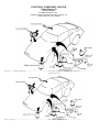
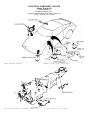
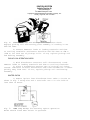
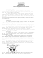
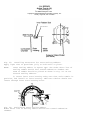
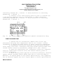
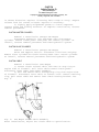
OPERATION
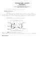
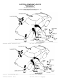
A reluctor (signal rotor) is mounted on the reluctor (rotor)
shaft. It turns inside 2 magnetic pick-up coils, one for the leading
side and one for the trailing side. See Fig. 2.
As each tooth of the reluctor approaches and then passes the
leading pick-up coil, a signal is generated. It is sent to the leading
ignitor, which breaks the primary circuit in the leading ignition
coil.
IGNITION SYSTEM
Article Text (p. 2)
1983 Mazda RX7
For www.iluvmyrx7.com
Copyright © 1998 Mitchell Repair Information Company, LLC
Sunday, August 26, 2001 03:31PM
As each tooth passes the leading pick-up coil, the previous
passing tooth approaches and becomes aligned with the trailing pick-up
coil. This triggers a signal to the trailing ignitor, which breaks the
primary circuit in the trailing ignition coil.
Therefore, immediately after the leading spark plug fires,
the trailing spark plug also fires, providing more complete and
efficient combustion while reducing HC and CO emissions.
As the primary circuit is broken in the leading and trailing
ignition coils, a voltage surge occurs in the secondary circuit of
the ignition coils. This high voltage is transmitted through the
leading and trailing high tension wires to the distributor, rotor and
spark plugs.
An emission control unit is also included in the ignition
control system, along with different sensing switches to provide
proper timing under varying engine operating conditions.
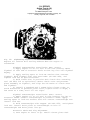
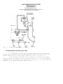
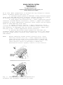
ADJUSTMENTS
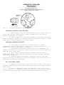
RELUCTOR-TO-PICK-UP COIL AIR GAP
1) Remove distributor cap and rotor. Turn distributor shaft
until the extended tooth of the reluctor (signal rotor) aligns with
core of pick-up coil. See Fig. 2.
2) Using a feeler gauge, check for .020-.035" (.5-.9 mm) air
gap. If gap is incorrect, replace pick-up coil and bearing assembly
or distributor drive shaft, if necessary.
Fig. 2: Adjusting Distributor Air Gap
Check air gap at all teeth and both pick-up coils.
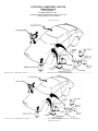
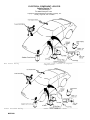
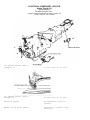
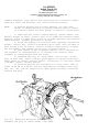
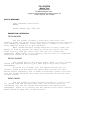
IGNITION TIMING
1) To adjust leading timing, loosen distributor lock nut,
and rotate distributor housing until correct timing is obtained. See
IGNITION SYSTEM
Article Text (p. 3)
1983 Mazda RX7
For www.iluvmyrx7.com
Copyright © 1998 Mitchell Repair Information Company, LLC
Sunday, August 26, 2001 03:31PM
Fig. 3.
2) To adjust trailing timing, loosen the screws securing the
trailing vacuum unit. Move the vacuum unit outward (to advance) or
inward (to retard). Retighten screws when correct timing is obtained.
Fig. 3: Adjusting Ignition Timing
Distributor position determines leading time. Vacuum unit position
adjusts trailing timing.
TESTING
HIGH TENSION WIRE RESISTANCE CHECK
Turn ignition switch "OFF". Connect ohmmeter leads to each
end of coil-to-distributor high tension wire. Resistance should not
exceed 16,000 ohms (plus or minus 400 ohms) per 39.37" (1 m).
IGNITION COIL RESISTANCE CHECK
Set an ohmmeter in the low scale. With ignition switch
turned "OFF", and coil wires disconnected, attach ohmmeter leads to
primary terminals of leading coil and then trailing coil. Primary
resistance should be 1.22-1.48 ohms for each ignition coil.
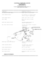
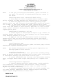
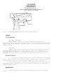
PICK-UP COIL RESISTANCE CHECK
1) Set an ohmmeter in the x100 scale. Turn ignition switch
"OFF". Disconnect connector between ignitor and distributor. See
Fig. 4.
IGNITION SYSTEM
Article Text (p. 4)
1983 Mazda RX7
For www.iluvmyrx7.com
Copyright © 1998 Mitchell Repair Information Company, LLC
Sunday, August 26, 2001 03:31PM
Fig. 4: Ohmmeter Hookup for Pick-Up Coil Resistance Check
Replace pick-up coil and bearing plate assembly if reading is not
600-700 ohms.
2)
to trailing
(20ø C) for
and bearing
Connect ohmmeter leads to leading terminals and then
terminals. Resistance should be 600-700 ohms at 68ø F
each set of pick-up coils. If not, replace pick-up coil
assembly.
PICK-UP COIL OPERATION CHECK
1) With distributor connector still disconnected, touch
ammeter leads to leading terminals and then to trailing terminals.
2) Place a screwdriver against core of pick-up coil being
tested. Indicator of meter should move each time screwdriver is taken
quickly away from core. If not, replace pick-up coil and bearing
assembly.
IGNITER CHECK
1) Remove ignitor from distributor base. Make a circuit as
shown in Fig. 5 using wire and a test bulb. Use a 12 volt bulb of
less than 10 watts.
Fig. 5: Test Lamp Hookup for Checking Ignitor Operation
Bulbs should flash when switch is operated.
IGNITION SYSTEM
Article Text (p. 5)
1983 Mazda RX7
For www.iluvmyrx7.com
Copyright © 1998 Mitchell Repair Information Company, LLC
Sunday, August 26, 2001 03:31PM
2) Quickly operate switch "ON " and "OFF", and make sure
test lamp flashes. If not, replace ignitor.
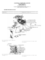
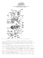
OVERHAUL
DISASSEMBLY
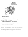
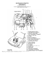
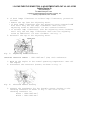
1) Remove distributor cap, rotor and seal cover. See Fig. 6.
Remove igniters and attaching screws from distributor housing. Remove
clips holding vacuum diaphragm links. Remove attaching screws and
vacuum control units from distributor housing. Remove condenser.
2) Remove reluctor shaft attaching screw from end of shaft.
Remove pick-up coil base bearing attaching screws. Remove reluctor,
reluctor shaft, pick-up coils and coil base bearing assembly from top
of distributor drive shaft.
3) Remove reluctor from reluctor shaft, using puller. Remove
spring pin. Remove governors by removing springs. Drive lock pin out
of drive gear, using a small drift. Remove gear and washers. Remove
drive shaft through top of distributor housing.
REASSEMBLY
1) Inspect distributor cap and rotor for cracks, carbon
tracks, and burned or corroded terminals.
2) Assemble distributor in reverse order of disassembly,
noting the following: Install reluctor shaft onto distributor drive
shaft, engaging slots of reluctor shaft and governor pins. Install
pick-up coil and coil base bearing assembly and tighten attaching
screws. Install reluctor on shaft, driving spring pin in with a punch.
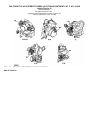
Fig. 6:
Disassembled View of RX7 Mitsubishi Distributor
END OF ARTICLE
STARTER - HITACHI/MITSUBISHI
Article Text
1983 Mazda RX7
For www.iluvmyrx7.com
Copyright © 1998 Mitchell Repair Information Company, LLC
Sunday, August 26, 2001 03:31PM
ARTICLE BEGINNING
1983 Starters
HITACHI & MITSUBISHI
Mazda
DESCRIPTION
Starter is a conventional 12-volt, 4-pole brush-type motor,
with either direct or reduction gear drive. The starter-mounted
solenoid shifts overrunning clutch and pinion into flywheel when
starter is energized.
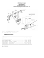
MITSUBISHI STARTER APPLICATION TABLE
ÄÄÄÄÄÄÄÄÄÄÄÄÄÄÄÄÄÄÄÄÄÄÄÄÄÄÄÄÄÄÄÄÄÄÄÄÄÄÄÄÄÄÄÄÄÄÄÄÄÄÄÄÄÄÄ
Model
Type or Part No.
Mazda
B2000 Pickup Gasoline
Man. Trans. .................... (1) HE19-18-400A
Auto. Trans. .................... (1) HE20-18-400
B2200 Pickup Diesel .............. (1) S211-18-400
GLC
FWD Sedan ....................... (1) E301-18-400
RWD Wagon
Man. Trans. ................... (1) D501-18-400
Auto. Trans. .................. (1) D502-18-400
RX7
Man. Trans. ..................... (1) N221-18-400
Auto. Trans. ................... (1) N202-18-400A
626 .............................. (1) FE05-18-400
(1) - Vehicle manufacturer's part number.
ÄÄÄÄÄÄÄÄÄÄÄÄÄÄÄÄÄÄÄÄÄÄÄÄÄÄÄÄÄÄÄÄÄÄÄÄÄÄÄÄÄÄÄÄÄÄÄÄÄÄÄÄÄÄÄ
TESTING
STARTER PERFORMANCE TESTS
No Load Tests
Connect starter in series with a 12-volt battery, a
voltmeter and a 1000 amp ammeter. Compare readings with Starter No
Load Specifications.
MITSUBISHI STARTER NO LOAD SPECIFICATIONS TABLE (1)
ÄÄÄÄÄÄÄÄÄÄÄÄÄÄÄÄÄÄÄÄÄÄÄÄÄÄÄÄÄÄÄÄÄÄÄÄÄÄÄÄÄÄÄÄÄÄÄÄÄÄÄÄÄÄÄÄÄÄÄÄÄÄÄÄÄÄÄÄÄÄ
Application
Mazda
B2000 Pickup
Max. Amps
................
53
Min. RPM
..........................
6800
STARTER - HITACHI/MITSUBISHI
Article Text (p. 2)
1983 Mazda RX7
For www.iluvmyrx7.com
Copyright © 1998 Mitchell Repair Information Company, LLC
Sunday, August 26, 2001 03:31PM
B2200 Pickup ............... 180
GLC
FWD Sedan .................. 53
RWD Wagon .................. 53
RX7
Man. Trans. ................ 60
Auto. Trans. .............. 100
626
Man. Trans. ................ 60
Auto. Trans. ............... 60
..........................
3800
..........................
..........................
6800
6800
..........................
..........................
6500
3500
..........................
..........................
6500
6600
(1) - Applied voltage of 11.5-12 volts.
ÄÄÄÄÄÄÄÄÄÄÄÄÄÄÄÄÄÄÄÄÄÄÄÄÄÄÄÄÄÄÄÄÄÄÄÄÄÄÄÄÄÄÄÄÄÄÄÄÄÄÄÄÄÄÄÄÄÄÄÄÄÄÄÄÄÄÄÄÄÄ
Load (Lock Torque) Test
Mount starter in a test stand to perform torque measurement
test. Follow manufacturer's instructions for test stand operation.
With voltage adjusted, ammeter reading and torque should be within
specifications.
MITSUBISHI STARTER LOAD TEST SPECIFICATIONS TABLE (1)
ÄÄÄÄÄÄÄÄÄÄÄÄÄÄÄÄÄÄÄÄÄÄÄÄÄÄÄÄÄÄÄÄÄÄÄÄÄÄÄÄÄÄÄÄÄÄÄÄÄÄÄÄÄÄÄÄÄÄÄÄÄÄÄÄÄÄÄÄÄÄ
Application
Max.
Amps
Mazda
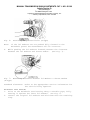
B2000 Pickup ........ 310
B2200 Pickup ....... 1050
GLC
FWD ................ 310
Wagon .............. 310
RX7
Man. Trans. ........ 600
Auto. Trans. ...... 1100
626 ................. 310
Torque
Ft. Lbs. (N.m)
Volts
............
............
5
2
...........
...........
5.4 (7.5)
21.7 (30)
............
............
5
5
...........
...........
5.4 (7.5)
5.4 (7.5)
............
............
............
5
4
5
...........
...........
...........
6.9 (9.6)
22.4 (31)
5.4 (7.5)
(1) - Turning speed not specified by manufacturer.
ÄÄÄÄÄÄÄÄÄÄÄÄÄÄÄÄÄÄÄÄÄÄÄÄÄÄÄÄÄÄÄÄÄÄÄÄÄÄÄÄÄÄÄÄÄÄÄÄÄÄÄÄÄÄÄÄÄÄÄÄÄÄÄÄÄÄÄÄÄÄ
SOLENOID TESTS
NOTE:
Make tests with solenoid removed from starter or remove
solenoid lead to starter before testing. Ensure solenoid
plunger and sleeve are clean and dry before performing
tests. Make tests in less than 10 seconds to prevent coil
damage.
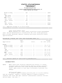
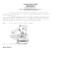
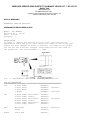
Pull-In Coil Test
1) Connect jumper between positive post of 12-volt battery
and "S" terminal. Connect a second jumper to negative battery
terminal and touch "M" (MT) terminal (and between terminal "S" and
switch body). See Fig. 1.
STARTER - HITACHI/MITSUBISHI
Article Text (p. 3)
1983 Mazda RX7
For www.iluvmyrx7.com
Copyright © 1998 Mitchell Repair Information Company, LLC
Sunday, August 26, 2001 03:31PM
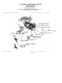
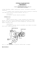
Fig. 1: Connections for Conducting Solenoid Pull-In Test
Remove solenoid-to-starter lead before testing.
2) If pinion moves outward (or plunger is pulled-in),
pull-in coil is good. If not, replace magnetic switch.
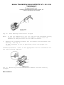
Hold-In Coil Test
1) Connect a jumper wire between the "M" (MT) terminal and
solenoid case. Apply 8 volts to "S" terminal to pull in the plunger.
See Fig. 2. Disconnect lead to "M" (MT) terminal.
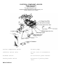
Fig. 2: Connections for Conducting Solenoid Hold-In Test
Make tests in less than 10 seconds to avoid solenoid damage.
2) If pinion remains out (plunger is pulled-in), hold-in
coil is good. If not, replace magnetic switch.
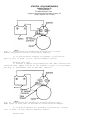
Return Test
STARTER - HITACHI/MITSUBISHI
Article Text (p. 4)
1983 Mazda RX7
For www.iluvmyrx7.com
Copyright © 1998 Mitchell Repair Information Company, LLC
Sunday, August 26, 2001 03:31PM
1) Apply 12 volts between "M" (MT) terminal and the solenoid
case. Pull pinion out and release it (push plunger into solenoid body
by hand). See Fig. 3.
Fig. 3: Connections for Conducting Return Test
Connect battery to "M" terminal and solenoid case.
2) If the case is short-circuited, the pinion will remain
out (plunger will be attracted). If nothing happens, solenoid is good.
REMOVAL & INSTALLATION
1) On all models, remove negative battery cable. If
necessary raise vehicle on hoist. Remove starter mounting bolts.
Remove starter from vehicle.
2) To install, reverse removal procedure.
OVERHAUL
DISASSEMBLY
NOTE:
Procedures may vary slightly between conventional and
reduction gear starters.
1) Loosen nut securing connecting plate-to-magnetic switch
"M" terminal. Remove screws securing magnetic switch and remove
switch (solenoid) assembly. Remove through bolts and brush cover
assembly. Tap yoke assembly loose with wooden mallet. Remove yoke,
armature assembly and pinion shift lever.
2) Remove pinion stop ring from end of armature shaft by
pushing stop ring to clutch side. Remove snap ring and overrunning
clutch assembly from armature shaft.
CLEANING & INSPECTION
STARTER - HITACHI/MITSUBISHI
Article Text (p. 5)
1983 Mazda RX7
For www.iluvmyrx7.com
Copyright © 1998 Mitchell Repair Information Company, LLC
Sunday, August 26, 2001 03:31PM
Clean all parts. Do not use grease dissolving solvent on
overrunning clutch, armature assembly, solenoid assembly or field
coils due to possible damage. Inspect all parts for damage or wear
and replace as required.
BENCH TESTS
Brushes & Springs
Check brush spring tension using a spring scale. Check brush
contact surface condition and brush length. Check lead clip and wire
connections and condition of brush holders. Replace as required. See
Brush Spring Tension and Minimum Brush Length Charts.
BRUSH SPRING TENSION TABLE
ÄÄÄÄÄÄÄÄÄÄÄÄÄÄÄÄÄÄÄÄÄÄÄÄÄÄÄÄÄÄÄÄÄÄÄÄÄÄÄÄÄÄÄÄÄÄÄÄÄÄÄÄÄÄÄ
Application
Mazda
B2000 & B2200 Pickups ...........
RX7 .............................
All Other Models ................
Ozs. (g)
50-62 (1415-1766)
50-92 (1415-2604)
46-60 (1302-1700)
ÄÄÄÄÄÄÄÄÄÄÄÄÄÄÄÄÄÄÄÄÄÄÄÄÄÄÄÄÄÄÄÄÄÄÄÄÄÄÄÄÄÄÄÄÄÄÄÄÄÄÄÄÄÄÄ
MINIMUM BRUSH LENGTH TABLE
ÄÄÄÄÄÄÄÄÄÄÄÄÄÄÄÄÄÄÄÄÄÄÄÄÄÄÄÄÄÄÄÄÄÄÄÄÄÄÄÄÄÄÄÄÄÄÄÄÄÄÄÄÄÄÄ
Application
Mazda
....................................
In. (mm)
.45 (11.5)
ÄÄÄÄÄÄÄÄÄÄÄÄÄÄÄÄÄÄÄÄÄÄÄÄÄÄÄÄÄÄÄÄÄÄÄÄÄÄÄÄÄÄÄÄÄÄÄÄÄÄÄÄÄÄÄ
Armature
Check external condition of armature for scoring or other
damage. Measure shaft distortion with dial indicator. Replace
armature if shaft distortion exceeds .004" (.10 mm).
Commutator
1) Inspect commutator for roughness, grooves, burns or
pitting. Sand lightly with 500 grit sandpaper if necessary. Check
commutator for out-of-round and mica insulators undercut to a depth
of .020-.031" (.5-.8 mm).
2) If necessary, commutator may be turned less than .04" (1
mm) from original size and mica undercut. Replace if excessively worn.
Field Coil
1) Check field coil continuity by connecting test probe of
circuit tester or an ohmmeter to the field coil positive terminal and
brush holder. If circuit is open, replace field coil.
2) Check for grounding of field coils by placing one probe
of circuit tester on starter housing and other probe to field coil
positive terminal. If little or no resistance, field coil is grounded
and must be replaced.
STARTER - HITACHI/MITSUBISHI
Article Text (p. 6)
1983 Mazda RX7
For www.iluvmyrx7.com
Copyright © 1998 Mitchell Repair Information Company, LLC
Sunday, August 26, 2001 03:31PM
Overrunning Clutch Assembly
1) Inspect pinion assembly and sleeve. Sleeve should slide
freely on armature shaft and spline. If damage or resistance is
noted, replace assembly.
2) Check pinion and flywheel teeth for excessive rubbing or
damaged teeth. Replace as required.
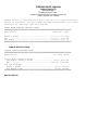
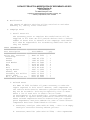
Pinion Gear Clearance
1) The clearance between the pinion gear and pinion stopper
collar should be .012-.098" (.3-2.5 mm) on Hitachi starters, or
.02-.08" (.51-2.03 mm) on Mitsubishi starters, when solenoid is
engaged. Adjust as necessary by changing shims between solenoid and
starter yoke.
2) On Mazda B2200 models, projection distance (starter
housing-to-front face of gear) should be .67" (17 mm). On Mazda RX-7
models, projection should be 1.06" (27.5 mm).
Pinion Case Bearing
Inspect bearing for wear and check side play. If clearance
exceeds .008" (.2 mm), replace bearing. New bearing clearance should
be .001-.004" (.025-.10 mm) for Hitachi or .002-.004" (.05-.10 mm)
for Mitsubishi starters.
NOTE:
Ensure that bearing is installed so that end of bearing is
flush with gear case end.
REASSEMBLY
To reassemble, reverse disassembly procedure. Fill gear case
on reduction gear models with grease. Lightly oil pinion and all
bearing surfaces.
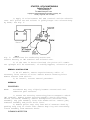
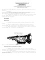
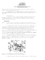
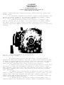
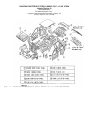
Fig. 4:
Measuring Pinion Edge-to-Pinion Stopper Clearance
STARTER - HITACHI/MITSUBISHI
Article Text (p. 7)
1983 Mazda RX7
For www.iluvmyrx7.com
Copyright © 1998 Mitchell Repair Information Company, LLC
Sunday, August 26, 2001 03:31PM
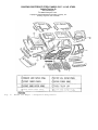
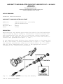
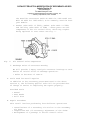
Fig. 5:
Disassembled View of Typical Mitsubishi Conventional Starter
END OF ARTICLE
A/C SYSTEM GENERAL DIAGNOSTIC PROCEDURES
Article Text
1983 Mazda RX7
For www.iluvmyrx7.com
Copyright © 1998 Mitchell Repair Information Company, LLC
Sunday, August 26, 2001 04:42PM
ARTICLE BEGINNING
1983-90 AIR CONDITIONING & HEAT
General Servicing Diagnostic Procedures
All Import Makes & Models
Diagnosis is an important first step in A/C system servicing.
To save time and effort, systems should be carefully checked to
identify the causes of poor performance. By using the following
diagnostic charts, defective components or system damage can be
quickly located. To identify problems that are specific to one system,
refer to the repair section of this manual. The charts in this section
apply to all systems.
ALTITUDE PRESSURE VARIATIONS
ALTITUDE PRESSURE VARIATIONS TABLE
ÄÄÄÄÄÄÄÄÄÄÄÄÄÄÄÄÄÄÄÄÄÄÄÄÄÄÄÄÄÄÄÄÄÄÄÄÄÄÄÄÄÄÄÄÄÄÄÄÄÄÄÄÄÄÄÄÄÄÄÄÄÄÄÄÄÄÄÄÄÄ
Altitude
(Ft. Above
Sea Level)
Absolute
Pressure of
Atmosphere (psi)
0 ...........................
1000 ........................
2000 ........................
3000 ........................
4000 ........................
5000 ........................
6000 ........................
7000 ........................
8000 ........................
9000 ........................
10,000 ......................
14.7
14.2
13.7
13.2
12.7
12.2
11.7
11.3
10.9
10.5
10.1
Gauge Altitude
Correction
(1) (psi)
............................. 0
.......................... -0.5
.......................... -1.0
.......................... -1.5
.......................... -2.0
.......................... -2.5
.......................... -3.0
.......................... -3.4
.......................... -3.8
.......................... -4.2
.......................... -4.6
(1) - Subtract correction shown from gauge readings.
ÄÄÄÄÄÄÄÄÄÄÄÄÄÄÄÄÄÄÄÄÄÄÄÄÄÄÄÄÄÄÄÄÄÄÄÄÄÄÄÄÄÄÄÄÄÄÄÄÄÄÄÄÄÄÄÄÄÄÄÄÄÄÄÄÄÄÄÄÄÄ
ALTITUDE VACUUM VARIATIONS
ALTITUDE VACUUM VARIATIONS TABLE
ÄÄÄÄÄÄÄÄÄÄÄÄÄÄÄÄÄÄÄÄÄÄÄÄÄÄÄÄÄÄÄÄÄÄÄÄÄÄÄÄÄÄÄÄÄÄÄÄÄÄÄÄÄÄÄÄÄÄÄÄÄÄÄÄÄÄÄÄÄÄ
Altitude
(Ft. Above
Sea Level)
Absolute
Pressure of
Atmosphere (psi)
0 ...........................
1000 ........................
2000 ........................
3000 ........................
4000 ........................
29.92
28.92
27.82
26.82
25.82
Gauge Altitude
Correction
(1) (psi)
............................ 0
......................... +1.0
......................... +2.1
......................... +3.1
......................... +4.1
A/C SYSTEM GENERAL DIAGNOSTIC PROCEDURES
Article Text (p. 2)
1983 Mazda RX7
For www.iluvmyrx7.com
Copyright © 1998 Mitchell Repair Information Company, LLC
Sunday, August 26, 2001 04:42PM
5000 ........................
6000 ........................
7000 ........................
8000 ........................
9000 ........................
10,000 ......................
24.92
23.92
23.02
22.22
21.32
20.52
.........................
.........................
.........................
.........................
.........................
.........................
+5.0
+6.0
+6.9
+7.7
+8.6
+9.4
(1) - Add correction shown to gauge readings.
ÄÄÄÄÄÄÄÄÄÄÄÄÄÄÄÄÄÄÄÄÄÄÄÄÄÄÄÄÄÄÄÄÄÄÄÄÄÄÄÄÄÄÄÄÄÄÄÄÄÄÄÄÄÄÄÄÄÄÄÄÄÄÄÄÄÄÄÄÄÄ
PREPARATION FOR TESTING
1)
2)
3)
4)
5)
Attach Low and High pressure gauges.
Start engine and allow to warm up.
Set system to "COOL" and blower to "HIGH".
Open car doors and hood.
Run engine at fast idle for 2-3 minutes.
AIR CONDITIONING SYSTEM PERFORMANCE CHECK TABLE
ÄÄÄÄÄÄÄÄÄÄÄÄÄÄÄÄÄÄÄÄÄÄÄÄÄÄÄÄÄÄÄÄÄÄÄÄÄÄÄÄÄÄÄÄÄÄÄÄÄÄÄÄÄÄÄÄÄÄÄÄÄÄÄÄÄÄÄÄÄ
PERFORM TESTS:
SHOULD BE:
IF:
ÄÄÄÄÄÄÄÄÄÄÄÄÄÄÄÄÄÄÄÄÄÄÄÄÄÄÄÄÄÄÄÄÄÄÄÄÄÄÄÄÄÄÄÄÄÄÄÄÄÄÄÄÄÄÄÄÄÄÄÄÄÄÄÄÄÄÄÄÄ
Temperature Check
*
*
*
Temperature Check Is
Switch to "LOW" blower.
Close doors.
Check outlet temperature.
35-45ø F
Too warm - Check control
lever operation, heater
water valve, cooling
system and gauge
readings.
ÄÄÄÄÄÄÄÄÄÄÄÄÄÄÄÄÄÄÄÄÄÄÄÄÄÄÄÄÄÄÄÄÄÄÄÄÄÄÄÄÄÄÄÄÄÄÄÄÄÄÄÄÄÄÄÄÄÄÄÄÄÄÄÄÄÄÄÄÄÄ
Visual Check
Visual Check Shows:
*
Compressor
Quiet, No Leaks
*
Condenser
*
Receiver-Drier
*
Sight Glass
*
High Side Lines
Dry & warm to touch
*
Low Side Lines
Dry & cool to touch
*
Expansion Valve
Free of Obstructions
Dry & warm to touch
Clear or few bubbles
Dry
Noisy - Check belts, oil
level, seals, gaskets,
reed valves.
Blocked - Clean off.
Plugged - Flush or
replace.
Frosty - Check for
restriction, replace
desiccant.
Bubbly, foamy or streaks
- Check gauge readings.
Frosty or very hot Check for restriction or
overcharge.
Frosty or warm - Check
for restriction, low
charge or bad valve.
Frosty - Check for
A/C SYSTEM GENERAL DIAGNOSTIC PROCEDURES
Article Text (p. 3)
1983 Mazda RX7
For www.iluvmyrx7.com
Copyright © 1998 Mitchell Repair Information Company, LLC
Sunday, August 26, 2001 04:42PM
*
STV
Dry & cool to touch
*
Evaporator
Dry & cold to touch
moisture or restriction.
Check sensing bulb.
Frosty or warm - Check
gauge readings for valve
malfunction.
Freezing or warm - Check
expansion valve, STV or
thermo switch.
ÄÄÄÄÄÄÄÄÄÄÄÄÄÄÄÄÄÄÄÄÄÄÄÄÄÄÄÄÄÄÄÄÄÄÄÄÄÄÄÄÄÄÄÄÄÄÄÄÄÄÄÄÄÄÄÄÄÄÄÄÄÄÄÄÄÄÄÄÄÄ
Gauge Readings
Gauge Readings are:
*
High Side Gauge
See Pressure Chart
*
Low Side Gauge
See Pressure Chart
Above or below normal See A/C Diagnosis.
Above or below normal See A/C Diagnosis.
ÄÄÄÄÄÄÄÄÄÄÄÄÄÄÄÄÄÄÄÄÄÄÄÄÄÄÄÄÄÄÄÄÄÄÄÄÄÄÄÄÄÄÄÄÄÄÄÄÄÄÄÄÄÄÄÄÄÄÄÄÄÄÄÄÄÄÄÄÄÄ
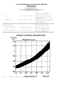
Fig. 1:
Ambient Temperature/Pressure A/C Chart
A/C SYSTEM GENERAL DIAGNOSTIC PROCEDURES
Article Text (p. 4)
1983 Mazda RX7
For www.iluvmyrx7.com
Copyright © 1998 Mitchell Repair Information Company, LLC
Sunday, August 26, 2001 04:42PM
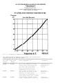
Fig. 2:
Evaporator Temperature/Pressure A/C Chart
AIR CONDITIONING DIAGNOSIS WITH GAUGES FOR SYSTEMS WITH
INSUFFICIENT OR NO COOLING TABLE
ÄÄÄÄÄÄÄÄÄÄÄÄÄÄÄÄÄÄÄÄÄÄÄÄÄÄÄÄÄÄÄÄÄÄÄÄÄÄÄÄÄÄÄÄÄÄÄÄÄÄÄÄÄÄÄÄÄÄÄÄÄÄÄÄÄÄÄÄÄÄ
Low Side
Gauge
High Side
Gauge
Other Symptoms (1)
Diagnosis
ÄÄÄÄÄÄÄÄÄÄÄÄÄÄÄÄÄÄÄÄÄÄÄÄÄÄÄÄÄÄÄÄÄÄÄÄÄÄÄÄÄÄÄÄÄÄÄÄÄÄÄÄÄÄÄÄÄÄÄÄÄÄÄÄÄÄÄÄÄÄ
NORMAL
NORMAL
NORMAL
NORMAL
NORMAL
NORMAL
No or few bubbles in sight
glass. High side gauge may
go high. Low side gauge
does not fluctuate with
compressor on/off cycle.
Cools okay in morning but
not during hot part of day.
Bubbles in sight glass.
Discharge air warm when low
side gauge drops into vacuum.
Thermostatic switch system
only - compressor cycles off
Some Air and
Moisture in
System
Excessive
Moisture in
System
Defective
Thermostatic
A/C SYSTEM GENERAL DIAGNOSTIC PROCEDURES
Article Text (p. 5)
1983 Mazda RX7
For www.iluvmyrx7.com
Copyright © 1998 Mitchell Repair Information Company, LLC
Sunday, August 26, 2001 04:42PM
and on too rapidly.
Cycling clutch systems only compressor doesn't turn on
soon enough. Discharge air
becomes warm as low side
pressure rises.
NORMAL
to
HIGH
NORMAL
LOW
LOW
LOW
LOW
LOW
LOW
Outlet air slightly cool.
Sweating or frost at
expansion valve.
LOW
LOW
LOW
HIGH
HIGH
LOW
HIGH
LOW
Outlet air slightly cool.
High side line cool to touch.
Sweating or frost on high
side.
Evaporator outlet pipe cold.
Low side goes into vacuum
when blower is disconnected.
Evaporator outlet pipe warm.
Outlet air warm.
Noise from compressor.
HIGH
HIGH
Outlet air warm. Liquid
line very hot. Bubbles in
sight glass.
HIGH
HIGH
Outlet air slightly cool.
Bubbles in sight glass.
HIGH
HIGH
Outlet air warm. Evaporator
outlet sweating and frost.
Bubbles in sight glass.
Outlet air slightly cool.
Sight glass clear. Outlet
air very warm.
Switch
Misadjusted
Thermostatic
Switch or
Defective
Pressure
Sensing Switch
Low R-12
Charge
Excessively
Low R-12
Charge
Expansion
Valve Stuck
Closed Screen
Plugged or
Sensing Bulb
Malfunction
Restriction
on High Side
STV Stuck
Open
STV Stuck
Closed
Compressor
Malfunction
Compressor
Malfunction
or R-12
Overcharge
Large Amount
of Air and
Moisture in
System
Expansion
Valve
Stuck Open
(1) - If equipped with a low refrigerant charge protection system,
compressor operation may have stopped.
ÄÄÄÄÄÄÄÄÄÄÄÄÄÄÄÄÄÄÄÄÄÄÄÄÄÄÄÄÄÄÄÄÄÄÄÄÄÄÄÄÄÄÄÄÄÄÄÄÄÄÄÄÄÄÄÄÄÄÄÄÄÄÄÄÄÄÄÄÄÄ
END OF ARTICLE
A/C SYSTEM PRECAUTIONS
Article Text
1983 Mazda RX7
For www.iluvmyrx7.com
Copyright © 1998 Mitchell Repair Information Company, LLC
Sunday, August 26, 2001 04:42PM
ARTICLE BEGINNING
AIR CONDITIONING & HEAT
A/C System Precautions
* PLEASE READ THIS FIRST *
CAUTION: When discharging air conditioning system, use only approved
refrigerant recovery/recycling equipment. Make every attempt
to avoid discharging refrigerant into the atmosphere.
BEFORE OPENING THE SYSTEM
Before disconnecting any lines or fittings, the system must
be completely discharged using approved refrigerant recovery/recycling
equipment.
DISCHARGING A/C SYSTEM
NOTE:
Recent findings by the EPA indicate that R-11, R-12 and R-113
are harmful to the Earths' protective Ozone layer. Make every
attempt possible, to avoid discharging R-11, R-12 or R-113
into the atmosphere.
1) Remove service valve caps and install gauges. For high
side gauge hose, Adapter (D81L-19703-A) must be used to connect to
high side service valve.
2) Place open end of center hose in garage exhaust outlet or
in a well ventilated area. Slightly open low side gauge valve and let
refrigerant escape slowly without loosing refrigerant oil.
3) When system is nearly discharged, using approved
refrigerant recovery/recycling equipment, open high side gauge valve
to release any pressure trapped in compressor. Close valves
immediately after discharging to prevent entry of moisture.
DISCONNECTING LINES & FITTINGS
1) After system is discharged, using approved refrigerant
recovery/recycling equipment, carefully clean entire area around
coupling nut to prevent dirt entering system. Always use two wrenches
to avoid twisting or distorting lines and fittings (hold fitting with
one wrench while loosening coupling nut with second wrench).
2) Cap or plug all LINES and FITTINGS immediately to prevent
entry of air and moisture into system. Do not remove these caps until
connections are being made.
COMPONENT REPLACEMENT
When components are replaced, system oil level must be
adjusted. Add refrigeration oil to replacement component. See
A/C SYSTEM PRECAUTIONS
Article Text (p. 2)
1983 Mazda RX7
For www.iluvmyrx7.com
Copyright © 1998 Mitchell Repair Information Company, LLC
Sunday, August 26, 2001 04:42PM
Compressor oil Check article, as well as, Component Oil Replacement
Quantities" chart under "A/C SYSTEM SPECS" article in this section.
USING R-12 REFRIGERANT - SAFETY PRECAUTIONS
1) Always work in a well-ventilated, clean area. Refrigerant
(R-12) is heavier than oxygen, and will displace oxygen in a confined
area. Always wear eye protection when working around air conditioning
systems and R-12. The system's high pressure can cause severe injury
to eyes and skin if a hose were to burst. R-12 evaporates quickly
when exposed to atmosphere, freezing anything it contacts.
2) Use care when handling refrigerant containers. DO NOT drop
or strike containers or expose refrigerant containers to excessive
heat. Containers must never be heated more than 125øF (52øC). Never
expose R-12 directly to open flame.
CAUTION: When R-12 is exposed to an open flame, drawn into a running
engine, or detected with a Halide (propane) leak tester,
poisonous phosgene gas is formed. Keep work areas ventilated
and avoid running engines near work area.
USING INDIVIDUAL R-12 CANS
Disposable refrigerant cans (referred to as one pound cans)
have a flat type seal or a screw type seal, and proper can tap must be
used for each type. Be sure sealing gasket on can tap is in good
condition. A proper safety can tap will prevent refrigerant from
flowing back into open can, as tap has a one-way flow control.
NOTE:
Recent findings by the EPA indicate that refrigerant is
harmful to the Earth's protective Ozone layer. When
discharging refrigerant avoid allowing refrigerant to enter
the atmosphere. Refrigerant recovery system should be used
when discharging the system.
MULTI-CAN DISPENSING VALVES
A multi-can dispensing valve allows attachment of several
cans of refrigerant, and is a good substitute when a bulk container is
not available. Cans are installed onto each leg of multi-can
dispensing valve in the same manner as the individual cans, and each
leg has its own can tap.
CAN TAP INSTALLATION FLAT TYPE SEAL CANS
On cam-lock or one-piece can taps, first turn the handle
outward to the fully open position. Securely engage locking lugs over
the can flange, and lock them in place by turning cam lock or locking
nut. Screw tap assembly into adapter so sealing gasket is fully seated
against the can top. Turn tap inward to pierce the can and close the
tap. DO NOT open tap until ready to purge the service hose or dispense
A/C SYSTEM PRECAUTIONS
Article Text (p. 3)
1983 Mazda RX7
For www.iluvmyrx7.com
Copyright © 1998 Mitchell Repair Information Company, LLC
Sunday, August 26, 2001 04:42PM
refrigerant into the system.
On 2-piece can taps, be certain tap handle is turned fully
inward to the closed position. Check that locking base is turned to
its outer limit. Securely engage locking lugs over the can flange.
Turn entire tap assembly (without disturbing the closed setting)
downward into the locking base to pierce the can. DO NOT open tap
until ready to dispense into system.
SCREW TYPE SEAL CANS
Ensure can tap is fully closed. Screw refrigerant can into
can tap fitting until tight. This will pierce the can. Connect tap to
center hose on manifold gauge set. DO NOT open tap until ready to
dispense R-12 into system.
WARNING: DO NOT open high side hand valve while air conditioning
system is in operation. This high pressure could rupture can
or fitting at safety can valve, resulting in damage and
personal injury.
CONNECTING LINES & FITTINGS
A new "O" ring should be used in all instances when
connecting lines and fittings (dip "O" ring in clean refrigeration oil
and make certain it is not twisted during installation). Always use
two wrenches to avoid twisting or distorting lines and fittings,
tighten coupling nuts securely.
PLACING SYSTEM IN OPERATION
After component replacement and/or system servicing has been
completed and all connections have been made, proceed as follows:
1) Evacuate the system using a vacuum pump.
2) Charge the system with new R-12 (refrigerant) according to
each individual vehicle as outlined in the
GENERAL COOLING SYSTEM SERVICING article. Also see Refrigerant
Capacity in this Section.
3) Leak test the system, with particular attention to all new
connections and components.
4) Make a performance test of the system. Never assume that a
recharging has automatically corrected a problem.
COMPRESSOR REMOVAL INFORMATION - ISOLATION METHOD
On systems which have compressors equipped with stem-type
service valves (Tecumseh), it is possible to isolate the compressor
for removal.
Isolating
Turn both high and low pressure manual valves to extreme
A/C SYSTEM PRECAUTIONS
Article Text (p. 4)
1983 Mazda RX7
For www.iluvmyrx7.com
Copyright © 1998 Mitchell Repair Information Company, LLC
Sunday, August 26, 2001 04:42PM
clockwise (front seat) position. Loosen cap on high pressure manual
valve connection to compressor and allow gas to escape until
compressor is relieved of pressure.
COMPRESSOR REMOVAL INFORMATION - DISCHARGE METHOD
This procedure is to be used on vehicles which have
compressor equipped with Schrader service valves. In these cases, the
compressor cannot be isolated and the system must be discharged, using
approved refrigerant recovery/recycling equipment, prior to compressor
removal.
END OF ARTICLE
TRANSMISSION REMOVAL & INSTALLATION - A/T
Article Text
1983 Mazda RX7
For www.iluvmyrx7.com
Copyright © 1998 Mitchell Repair Information Company, LLC
Sunday, August 26, 2001 04:50PM
ARTICLE BEGINNING
Automatic Transmission Removal
1983 MAZDA
PICKUP
REMOVAL
1) Raise vehicle and support with safety stands. Disconnect
battery tube. Remove shift rod from right side of transmission case.
Remove bolts and nuts attaching exhaust pipe and catalytic converter.
2) Remove solenoid and inhibitor switch connector. Remove
speedometer cable. Remove drive shaft. Fit main shaft holder (49 0259
440) into main shaft in transmission case to prevent oil leak. Remove
starter and gusset plates.
3) Remove lower covers from front and rear of engine. Remove
converter housing bolts.Remove vacuum pipe clip. Remove bolt, pipe
clip and installation blot from left side of transmission.
4) Remove connector bolts and washers from left side of
transmission. Remove engine hanger. Remove clip and bolt from top of
converter housing. Remove oil filter pipe and level gauge.
5) Securely support transmission with hydraulic jack. Remove
transmission mounts. Cover oil filter pipe and connector bolt mounting
hole on transmission case.
6) Insert screwdriver through torque converter installation
hole in drive plate. Press against torque converter to prevent it form
separating when transmission is removed. Remove transmission-to-engine
bolts and slowly lower transmission out of vehicle.
INSTALLATION
Reverse removal procedure to install transmission. After
transmission is installed, rotate cranshaft several times to be sure
that transmission rotates freely without binding.
GLC (RWD), 626 & RX-7
REMOVAL
1) Disconnect negative battery cable. On RX-7, remove air
cleaner, converter housing upper and side covers, and top bolts
attaching transmission to engine. On models so equipped, disengage
torsion shaft from accelerator linkage. Raise vehicle and support with
safety stands
2) Drain fluids from transmission. Remove drive shaft. Use
output shaft to prevent oil leakage from rear of transmission. Remove
any exhaust pipe from manifold. Disconnect shift linkage from manual
shaft on transmission
3) Disconnect all electrical and vacuum leads from
transmission. Disconnect speedometer cable. Remove oil filter tube
TRANSMISSION REMOVAL & INSTALLATION - A/T
Article Text (p. 2)
1983 Mazda RX7
For www.iluvmyrx7.com
Copyright © 1998 Mitchell Repair Information Company, LLC
Sunday, August 26, 2001 04:50PM
from transmission, then disconnect both oil cooler pipes.
4) Disconnect governor tube from converter housing and
transmission case (if equipped). Support transmission with wood block
between oil pan and transmission jack.
5) Remove converter inspection plates. Mark converter and
flywheel for realignment reference during installation. Remove torque
converter -to-flywheel attachment bolts.
6) Remove rear mount and crossmember mounting bolts. Remove
starter ( lower transmission as needed to gain access to starter
bolts). Remove transmission-to-engine bolts and slowly lower
transmission out of vehicle.
INSTALLATION
Reverse removal procedure to install transmission, noting
the following: When installing torque converter, be sure that notch in
converter lines up with notch in oil pump. When bolting converter to
flywheel, be sure to align mark made during removal to ensure proper
alignment. After transmission is installed, rotate crankshaf several
times to be sure that transmission rotates freely without binding.
GLC (FWD)
REMOVAL
1) Drain all fluid from transaxle assembly (oil pan must be
removed to completely drain transaxle as drain plug along will not
drain all the fluid ). Disconnect negative cable from battery.
Disconnect speedometer cable , inhibitor switch connector, neutral
switch connector and kickdown solenoid connector.
2) Remove graphic diaphragm lines. Raise front end of vehicle
and support. Remove wheel, disconnect lower control arm ball joints
and pull drive shaft out of transaxle. Use care when removing drive
shaft to avoid stressing outer constant velocity joint to its limit,
as this will damage the joint. Remove engine undercover.
3) Attach engine support to engine hanger and support engine.
Remove crossmember. Disconnect oil hose from oil pipe and plug ends of
hose and pipe. Remove rear transmission mount. Remove starter, end
cover and torque converter to-drive plate retaining bolts.
4) Support transaxle with jack and remove transaxle-to-engine
retaining bolts. Lower transaxle assembly out of vehicle. Use care
when removing transaxle so that torque converter does not fall out.
INSTALLATION
Reverse removal procedure to install
END OF ARTICLE
TRANSMISSION SERVICING - A/T
Article Text
1983 Mazda RX7
For www.iluvmyrx7.com
Copyright © 1998 Mitchell Repair Information Company, LLC
Sunday, August 26, 2001 04:51PM
ARTICLE BEGINNING
1983 Automatic Transmission Servicing
MAZDA
RX7
IDENTIFICATION
TRANSMISSION CODES
ÄÄÄÄÄÄÄÄÄÄÄÄÄÄÄÄÄÄÄÄÄÄÄÄÄÄÄÄÄÄÄÄÄÄÄÄÄÄÄÄÄÄÄÄÄÄÄÄÄÄÄÄÄÄÄÄÄÄÄÄÄÄÄÄÄÄÄÄÄÄ
Application
Codes
RX7
3N71B
..........................................................
ÄÄÄÄÄÄÄÄÄÄÄÄÄÄÄÄÄÄÄÄÄÄÄÄÄÄÄÄÄÄÄÄÄÄÄÄÄÄÄÄÄÄÄÄÄÄÄÄÄÄÄÄÄÄÄÄÄÄÄÄÄÄÄÄÄÄÄÄÄÄ
LUBRICATION
SERVICE INTERVALS
Inspect automatic transmission fluid level every 7,500 miles
or 8 months.
FLUID LEVEL
1) Check fluid with vehicle on level floor. Apply parking
brake firmly and run engine approximately 2 minutes at 1200 RPM.
2) With engine running at normal idle, move selector lever
through all gears, pausing at each gear to allow for engagement.
3) Return to "P" position and leave engine running. Wipe
area clean around dipstick filler tube and remove dipstick.
4) Wipe dipstick clean, reinsert, withdraw, and note
reading. If between "L" and "F" marks, level is satisfactory. If not,
add fluid.
FLUID TYPE
Automatic Transmission Fluid (ATF)
Type "F"
FLUID CAPACITY
6.6 qts. (6.2L)
DRAINING & REFILLING
Transmission
1) If draining and refilling is required for any operation,
remove pan bolts and allow fluid to drain. Remove pan and gasket,
(discard gasket).
2) Clean pan thoroughly and reinstall new gasket, tightening
TRANSMISSION SERVICING - A/T
Article Text (p. 2)
1983 Mazda RX7
For www.iluvmyrx7.com
Copyright © 1998 Mitchell Repair Information Company, LLC
Sunday, August 26, 2001 04:51PM
pan bolts to 36-60 INCH lbs. (4-9 N.m). Add fluid, make sure not to
overfill.
Transaxle
1) Drain oil by removing drain plug on bottom of
differential. Remove speedometer driven gear and oil pan. Clean oil
pan. Replace oil pan and speedometer driven gear.
2) Replace oil through oil filler tube. Place selector lever
in "P", warm engine, and check oil level. Oil level must not be
higher than "F" on gauge.
ADJUSTMENT
BRAKE BAND
1) Loosen servo piston stem lock nut and back off a few
turns.
2) Using a torque wrench, tighten servo piston stem to
108-132 INCH lbs. (12-15 N.m), then back off piston stem 2 turns.
3) Hold piston stem in this position and tighten lock nut to
132-348 INCH lbs. (15-39 N.m) on RWD models.
Fig. 1:
RX7 Transmission Brake Band Adjustment
KICKDOWN SWITCH & DOWNSHIFT SOLENOID
1) Depress accelerator pedal to limit. Near wide open
throttle, click should be heard from solenoid. Switch must operate at
or after 7/8 of pedal travel.
2) If not, loosen switch retaining nut and adjust switch to
engage when pedal is at 7/8 of its full travel, tighten retaining nut
and check solenoid.
TRANSMISSION SERVICING - A/T
Article Text (p. 3)
1983 Mazda RX7
For www.iluvmyrx7.com
Copyright © 1998 Mitchell Repair Information Company, LLC
Sunday, August 26, 2001 04:51PM
Fig. 2:
Kickdown Switch and Downshift Solenoid
SHIFT LINKAGE
NOTE:
Before linkage is adjusted, be sure engine idle is properly
set.
RX7
Remove boot plate. Place selector lever in "P" position.
Loosen selector lever plate bolt. Place transmission in "P" position.
Tighten selector lever plate bolt and replace boot.
SELECTOR LEVER HANDLE ADJUSTMENT
Loosen and back off lock nut. Screw handle fully down until
no play exists in the push button. Unscrew handle 1 complete turn at
a time until smooth shifting operation is obtained. Tighten lock nut.
NEUTRAL SAFETY SWITCH
1) After checking and adjusting shift linkage, place the
transmission lever in the "N" position.
2) Loosen safety switch retaining bolts. Remove screw from
alignment pin hole at bottom of switch.
3) Rotate switch and insert a .078" (2 mm) diameter
alignment pin through the alignment hole and into hole of internal
rotor. Tighten switch retaining bolts and remove alignment pin.
4) Reinstall alignment pin hole screw. Check operation of
switch. The engine should only start in "N" or "P" position.
Fig. 3:
Adjusting Neutral Safety Switch On RX7 Transmissions
TRANSMISSION SERVICING - A/T
Article Text (p. 4)
1983 Mazda RX7
For www.iluvmyrx7.com
Copyright © 1998 Mitchell Repair Information Company, LLC
Sunday, August 26, 2001 04:51PM
END OF ARTICLE
BRAKE SYSTEM
Article Text
1983 Mazda RX7
For www.iluvmyrx7.com
Copyright © 1998 Mitchell Repair Information Company, LLC
Sunday, August 26, 2001 04:54PM
ARTICLE BEGINNING
1983 Brakes
MAZDA
GLC Wagon, Pickups, RX7
DESCRIPTION
Brake system is hydraulically-operated, using a tandem
master cylinder and power brake unit. Front brakes are floating
caliper disc. Rear brakes on most models are leading/trailing drums.
Floating caliper rear disc brakes are available on RX7 as an
option. Proportioning valves are used on most models to prevent
premature lockup of rear wheels.
ADJUSTMENT
REAR DRUM BRAKE SHOES
GLC Wagon, RX7 & Pickups
1) Raise and support rear of vehicle. Release parking brake.
Remove rear wheel. Through the hole in the brake drum of the GLC
Wagon or on the backing plate of all others, remove the star wheel
plug. Insert a flat-tipped screwdriver, and move the star wheel
forward until the wheel is locked. See Fig. 1.
Fig. 1:
Adjusting Rear Brake Shoe-to-Drum Position
2) On all backing plates, remove the pawl lever hole plug.
Insert a flat-tipped screwdriver through hole. Push on the pawl lever
self-adjuster, so the star wheel may be moved in the reverse
direction.
3) Back off the star wheel about 3 or 4 notches, so the
BRAKE SYSTEM
Article Text (p. 2)
1983 Mazda RX7
For www.iluvmyrx7.com
Copyright © 1998 Mitchell Repair Information Company, LLC
Sunday, August 26, 2001 04:54PM
wheel turns freely. Repeat procedure for opposite side. Adjust the
parking brake. Install plugs in the adjusting holes.
BRAKE PEDAL HEIGHT ADJUSTMENT
ÄÄÄÄÄÄÄÄÄÄÄÄÄÄÄÄÄÄÄÄÄÄÄÄÄÄÄÄÄÄÄÄÄÄÄÄÄÄÄÄÄÄÄÄÄÄÄÄÄÄÄÄÄÄÄÄÄÄÄÄÄÄÄÄÄÄÄÄÄÄ
Application
GLC Wagon
Man. Trans. ....................................
Auto. Trans. ...................................
RX7 ..............................................
B2000 & B2200 ....................................
In. (mm)
7.5-7.7
7.7-7.9
7.5-7.7
8.1-8.3
(190-195)
(195-200)
(190-195)
(205-210)
ÄÄÄÄÄÄÄÄÄÄÄÄÄÄÄÄÄÄÄÄÄÄÄÄÄÄÄÄÄÄÄÄÄÄÄÄÄÄÄÄÄÄÄÄÄÄÄÄÄÄÄÄÄÄÄÄÄÄÄÄÄÄÄÄÄÄÄÄÄÄ
PARKING BRAKE
1) With service brakes properly adjusted, raise and support
the rear of the vehicle. Remove parking brake lever boot or console,
if necessary. Release the brake lever. Turn the adjusting screw or
nut to obtain specified clearance. On Pickups, turn adjusting nut at
equalizer under the vehicle.
2) The lever should be pulled with a force of 22 lbs. to
obtain a stroke of 3-7 notches on GLC Wagon, 5-9 notches on GLC, 6-8
notches on RX7, 7-9 notches on 626, and 5-10 notches on Pickups.
3) Reinstall brake lever boot or console. Remove supports
and lower vehicle. On all models, operate parking brake several times
and make sure rear wheels rotate freely.
NOTE:
Insure that the rear brakes are not dragging and the parking
brake warning light is activated when the lever is pulled 1
notch.
BRAKE WARNING LIGHT
All Models (If Equipped)
1) Light indicates parking brake is engaged and also warns
of low fluid level. With engine running, light should glow when
parking brake lever is pulled 1 notch and go off when lever is fully
released.
2) To check warning light operation with engine running,
release parking brake lever and ensure light is off. Raise master
cylinder reservoir cap and light should glow. If not, check switch
and wire connector.
REMOVAL & INSTALLATION
FRONT DISC BRAKE PADS
Removal
1) Raise and support the front of the vehicle. Remove the
wheels. Detach brake hose attachment from shock absorber, if
necessary.
BRAKE SYSTEM
Article Text (p. 3)
1983 Mazda RX7
For www.iluvmyrx7.com
Copyright © 1998 Mitchell Repair Information Company, LLC
Sunday, August 26, 2001 04:54PM
2) On RX7 remove lower caliper guide pin and
pivot caliper body up out of way. On GLC Wagon and Pickups remove
locking clips and stopper plates.
3) Remove caliper body and hang from frame with wire. Do not
disconnect hydraulic lines. On all models, remove anti-rattle springs
(clips), pads, and shims, if equipped.
Installation
1) To install, reverse removal procedure. Before mounting
caliper, loosen bleed screw, and seat piston. Tighten bleed screw.
2) After pad installation, depress brake pedal several times
to seat pads. Bleed hydraulic system, if required.
NOTE:
Grease pad mounting support, caliper contact area, and shims
with special grease (NLGI No. 2 or equivalent).
REAR DISC BRAKE PADS
Removal (RX7)
1) Raise and support the rear of the vehicle. Remove wheel.
Disconnect parking brake cable from caliper. Remove lower caliper
attaching bolt.
2) Lift the lower side of caliper. Remove anti-rattle
spring. Remove disc brake pads and shims.
Installation
1) Using brake piston wrench (49 FA18 602), turn piston
clockwise until piston is inserted into caliper fully.
2) Position piston so that dowel on pad will seat in piston
stopper groove. To complete installation, reverse removal procedure.
FRONT DISC BRAKE CALIPER
Removal
1) Raise and support the front of the vehicle. Remove the
wheel. Disconnect and plug the fluid line at caliper. On RX7, remove
lower caliper bolt, lift the caliper body, and remove by sliding
toward the inside of the vehicle.
2) On GLC Wagon and Pickups, remove locking clips, stopper
plates, and anti-rattle spring. Lift off caliper. Remove disc pads as
previously described.
Installation
To install, reverse removal procedure and bleed hydraulic
system.
REAR BRAKE CALIPER
Removal (RX7)
1) Raise and support the rear of the vehicle. Remove the
wheel. Disconnect parking brake cable from caliper.
2) Remove caliper attaching bolt (lower side). Lift up
BRAKE SYSTEM
Article Text (p. 4)
1983 Mazda RX7
For www.iluvmyrx7.com
Copyright © 1998 Mitchell Repair Information Company, LLC
Sunday, August 26, 2001 04:54PM
caliper. Slide the caliper toward the inside of the vehicle and
remove the caliper. Disconnect the brake hose from the caliper.
Installation
To install caliper, reverse removal procedure and bleed
hydraulic system.
FRONT DISC BRAKE ROTOR
Removal (All Models)
1) With caliper assembly removed, remove wheel hub grease
cap, cotter pin, lock plate and ring adjusting lock nut.
2) Remove thrust washer and outer bearing from hub. Slide
hub and rotor assembly from spindle. On Pickups, place wheel in a
soft-jawed vise, make mating marks, remove hub-to-rotor bolts, and
separate rotor from hub.
Installation
To install, reverse removal procedure, and tighten
hub-to-rotor bolts evenly. Adjust wheel bearings. See Wheel Bearing
Adjustment in SUSPENSION section.
REAR BRAKE DRUM
Removal (All Models)
Raise and support the rear of the vehicle. Release parking
brake. Remove the wheel. On Pickups, remove brake drum retaining
screws and insert into tapped holes of brake drum. Turn screws evenly
and force brake drum off flange.
Installation (All Models)
To install, reverse removal procedure. Tighten retaining
screws evenly (if equipped). On GLC & 626, adjust wheel bearings. See
Wheel Bearing Adjustment in SUSPENSION section.
Fig. 2: Exploded View of GLC Wagon Rear Brakes
Other models are similar.
BRAKE SYSTEM
Article Text (p. 5)
1983 Mazda RX7
For www.iluvmyrx7.com
Copyright © 1998 Mitchell Repair Information Company, LLC
Sunday, August 26, 2001 04:54PM
REAR BRAKE SHOES
Removal (All Models)
1) With brake drum removed, remove brake shoe return
springs, retaining springs and guide pins. Remove brake shoes.
2) Remove parking brake strut and disconnect parking brake
cable from operating lever of secondary shoe.
Installation
1) Lubricate adjusting screw threads and contact surfaces of
shoes and backing plate with brake grease. Install parking brake
operating lever to secondary shoe and secure with clip. Engage
operating lever with parking brake cable.
2) Position operating strut between slots of shoes. Mount
assembly to backing plate so slots in shoes are toward adjusting
screws. Install return springs and retainer springs.
MASTER CYLINDER
Removal
1) Disconnect fluid level sensor coupler, if equipped.
Disconnect and plug hydraulic lines at master cylinder to prevent
entry of dirt and loss of fluid.
2) Remove nuts attaching master cylinder to firewall or
power brake unit and remove master cylinder from vehicle. On RX7,
remove proportioning valve by-pass bolt.
Installation
To install, reverse removal procedure and bleed hydraulic
system.
POWER BRAKE UNIT
Removal
1) Remove master cylinder from power brake unit before
removing power brake unit. Disconnect vacuum line at power brake unit.
2) From inside vehicle, remove cotter pin and clevis pin
attaching push rod to brake pedal, and separate.
3) Remove nuts retaining power unit to firewall. Remove
power brake unit and master cylinder as an assembly. Separate master
cylinder from power brake unit.
Installation
To install, reverse removal procedure and bleed hydraulic
system.
OVERHAUL
FRONT DISC BRAKE CALIPER
Disassembly
1) Thoroughly clean exterior of caliper and remove retainer
BRAKE SYSTEM
Article Text (p. 6)
1983 Mazda RX7
For www.iluvmyrx7.com
Copyright © 1998 Mitchell Repair Information Company, LLC
Sunday, August 26, 2001 04:54PM
and dust boot. Place a piece of wood in front of piston.
2) Apply compressed air to fluid inlet and remove piston.
Tap caliper with plastic hammer, if required. Remove piston seal
without damaging caliper bore.
Fig. 3:
Exploded View of Pickup Front Disc Brake Caliper
Cleaning & Inspection
1) Wash all parts in alcohol or brake fluid and air dry.
Inspect cylinder bore and piston for scoring, scratches or rust.
Replace defective parts.
2) Minor damage may be removed with crocus cloth. Always
replace dust boot and piston seal when caliper is disassembled.
Reassembly
1) Apply clean brake fluid to cylinder bore, piston and
piston seal. Seat piston seal in caliper bore.
2) Install piston carefully into cylinder bore and install
dust boot and retainer.
Fig. 4:
Exploded View of RX7 Front Brake Caliper
REAR DISC BRAKE CALIPER
BRAKE SYSTEM
Article Text (p. 7)
1983 Mazda RX7
For www.iluvmyrx7.com
Copyright © 1998 Mitchell Repair Information Company, LLC
Sunday, August 26, 2001 04:54PM
Disassembly (RX7)
1) Remove dust boot retainer and boot. Turn piston
counterclockwise with disc brake piston wrench (49 FA18 602), and
screw out piston. Remove piston seal.
2) Remove boot retainer. Slip off boot. Remove snap ring.
Compress conical spring in caliper with spring compressor (49 FA18
601), valve spring lifter arm (49 0636 100A), and removing plate (49
E301 144).
3) Remove parking brake crank, torsion spring and strut.
Remove adjusting bolt and conical spring assembly. Press out needle
roller bearings.
Inspection
1) Clean all parts in brake fluid or alcohol. Air dry parts.
Inspect caliper bore for scratches, scoring or rust. Minor damage can
be removed by polishing with crocus cloth.
CAUTION: Never use gasoline or kerosene when cleaning caliper parts.
2) Inspect needle roller bearing, strut, adjusting bolt, and
parking brake crank for corrosion, wear or damage. Check torsion
spring and conical spring for corrosion, weakness or damage.
3) Check piston and sleeve nut for excessive play. It should
be within .012-.020" (.3-.5 mm).
Reassembly
1) Assemble the caliper in the reverse order of disassembly.
Use new piston and dust seals. Three kinds of grease contained in
seal kit must be used.
2) White grease is for caliper slide bolts and mounting
bolts. Orange grease is for bearings, adjusting bolt, strut and
piston boot. Pink grease is for piston seal.
3) Lubricate the piston and caliper bore with clean brake
fluid. Press in needle roller bearing so that arrow on bearing faces
outward.
4) Assemble conical spring and adjusting bolt. See Fig. 5.
Install adjusting bolt assembly, strut and torsion spring in the
caliper. Install piston using disc brake wrench, as described under
Disc Brake Pad Installation.
Fig. 5: Proper Installation of Conical Spring and Adjusting Bolt
Apply orange grease, supplied in seal kit, to adjusting bolt.
BRAKE SYSTEM
Article Text (p. 8)
1983 Mazda RX7
For www.iluvmyrx7.com
Copyright © 1998 Mitchell Repair Information Company, LLC
Sunday, August 26, 2001 04:54PM
WHEEL CYLINDERS
Disassembly
Remove dust boots. Remove piston assemblies by pressing on
cylinder cup to force out filling blocks and return spring.
Cleaning & Inspection
1) Clean all parts in alcohol or brake fluid. Check cylinder
bore and pistons for scores, roughness or wear.
2) Check clearance between cylinder bore and pistons.
Replace if clearance exceeds .006" (.15 mm). Check cups for
deformation. Replace as necessary.
Fig. 6: Exploded View of Wheel Cylinder
Flat side of cylinder cups face outward.
Reassembly
1) Reverse disassembly procedure. Coat all parts with clean
brake fluid before reassembly.
2) When installing cylinder cups, make sure flat side of cup
faces outward.
MASTER CYLINDER
Disassembly
1) Thoroughly clean outside of master cylinder, and pour out
any remaining brake fluid. If equipped, remove reservoir and dust
boot. Depress primary piston assembly. See Fig. 7.
2) From rear of cylinder bore, remove retaining ring ,
washer, primary piston assembly, and return spring. Remove stopper
bolt and secondary piston by blowing compressed air through the
outlet port. See Fig. 8.
3) Carefully withdraw secondary piston assembly and return
spring. Remove fittings, check valves, and springs.
BRAKE SYSTEM
Article Text (p. 9)
1983 Mazda RX7
For www.iluvmyrx7.com
Copyright © 1998 Mitchell Repair Information Company, LLC
Sunday, August 26, 2001 04:54PM
Fig. 7: Exploded View of Typical Master Cylinder
Some models may vary slightly.
Cleaning & Inspection
1) Clean all parts in alcohol or brake fluid. Check all
parts for scoring, roughness or wear. Check piston-to-cylinder
clearance.
2) If clearance exceeds .006" (.15 mm), replace parts as
necessary. Remove all foreign matter from internal passages and
recesses with compressed air.
3) Check cylinder cups for deformation and replace as
required.
Reassembly
1) Reverse disassembly procedure. Coat all parts with clean
brake fluid before reassembly. Use new gaskets at all hydraulic
unions.
2) When assembled, make sure piston cups do not cover
compensating ports. Make sure valve with hole in center, faces front
side outlet hole.
POWER BRAKE UNIT
NOTE:
Power brake units vary slightly between model applications.
The following general overhaul procedures can be used if
attention is paid to specific order of components.
Disassembly
1) Remove master cylinder and check valve from power unit.
Place power unit in a vise with push rod up.
2) Scribe alignment marks on front and rear shells to assure
reassembly in original position. Remove clevis, lock nut, and dust
boot from rear shell.
CAUTION: Separate front and rear shells carefully. Spring tension may
cause rear shell to release quickly.
BRAKE SYSTEM
Article Text (p. 10)
1983 Mazda RX7
For www.iluvmyrx7.com
Copyright © 1998 Mitchell Repair Information Company, LLC
Sunday, August 26, 2001 04:54PM
3) Attach suitable tool to rear shell mounting studs. Press
down on tool while rotating it clockwise to unlock rear shell.
4) Lift rear shell assembly from power unit, remove air
silencer retainer, and separate diaphragm from power piston assembly.
Remove valve rod with plunger assembly from rear shell.
5) Remove lock plate and press the valve rod in to remove
the valve retainer key. Remove valve rod and plunger assembly. Remove
air silencer and filter.
NOTE:
Service the valve rod plungers as an assembly.
6) Remove retainer, bearing, and rear seal.
NOTE:
Never remove the rear seal from the rear shell unless seal
is defective and a new one is available.
7) Remove the push rod, front seal, and the support plate.
Cleaning & Inspection
1) Clean all parts and blow dry with compressed air. Inspect
all rubber parts for cuts, nicks, deterioration or other damage.
2) Check power piston for cracks, distortion, chipping, and
damaged seats. Inspect front and rear shells for scratches, scores,
pits, dents or other damage. Replace any defective parts.
Reassembly
1) Reverse disassembly procedure. Apply silicone grease to
parts before reassembly. When assembling rear shell to front shell,
make sure index marks are aligned.
2) Before installing master cylinder to power unit, measure
clearance between primary piston and power unit push rod. Clearance
on RX7 & GLC Wagon should be .004-.012" (.1-.3 mm).
3) On all other models, clearance should be .004-.020"
(.1-.5 mm). If clearance is not to specifications, correct by
adjusting push rod length.
Fig. 8: Exploded View of Typical Power Brake Unit
Some models may vary slightly.
BRAKE SYSTEM
Article Text (p. 11)
1983 Mazda RX7
For www.iluvmyrx7.com
Copyright © 1998 Mitchell Repair Information Company, LLC
Sunday, August 26, 2001 04:54PM
TORQUE SPECIFICATIONS
TORQUE SPECIFICATIONS TABLE
ÄÄÄÄÄÄÄÄÄÄÄÄÄÄÄÄÄÄÄÄÄÄÄÄÄÄÄÄÄÄÄÄÄÄÄÄÄÄÄÄÄÄÄÄÄÄÄÄÄÄÄÄÄÄÄÄÄÄÄÄÄÄÄÄÄÄÄÄÄÄ
Application
Caliper Mounting Bracket
Pickups ............................................
GLC Wagon ..........................................
Caliper Guide Pin ....................................
Ft. Lbs. (N.m)
40-47 (55-65)
33-40 (45-55)
33-40 (45-55)
ÄÄÄÄÄÄÄÄÄÄÄÄÄÄÄÄÄÄÄÄÄÄÄÄÄÄÄÄÄÄÄÄÄÄÄÄÄÄÄÄÄÄÄÄÄÄÄÄÄÄÄÄÄÄÄÄÄÄÄÄÄÄÄÄÄÄÄÄÄÄ
DISC SPECIFICATIONS
DISC BRAKE ROTOR SPECIFICATIONS TABLE
ÄÄÄÄÄÄÄÄÄÄÄÄÄÄÄÄÄÄÄÄÄÄÄÄÄÄÄÄÄÄÄÄÄÄÄÄÄÄÄÄÄÄÄÄÄÄÄÄÄÄÄÄÄÄÄÄÄÄÄÄÄÄÄÄÄÄÄÄÄÄ
Application
In. (mm)
GLC Wagon
Disc. Diameter ......................................... 9.02 (229)
Lateral Runout ......................................... .002 (.06)
Parallelism ........................................................
Original Thickness ...................................... .512 (13)
Min. Refinish Thickness ............................................
Discard Thickness ....................................... .472 (12)
RX7
Disc. Diameter
Front / Rear ....................................................
Lateral Runout
Front / Rear ......................................... .004 (.10)
Parallelism ........................................................
Original Thickness
Front ................................................. .709 (18)
Rear .................................................. .394 (10)
Min. Refinish Thickness ............................................
Discard Thickness
Front ................................................. .669 (17)
Rear ................................................... .354 (9)
B2000
Disc. Diameter ........................................ 10.08 (256)
Lateral Runout ......................................... .004 (.10)
Parallelism ........................................................
Original Thickness ...................................... .472 (12)
Min. Refinish Thickness ............................................
Discard Thickness ....................................... .433 (11)
B2200
Disc. Diameter ........................................ 10.08 (256)
Lateral Runout ......................................... .004 (.10)
Parallelism ........................................................
BRAKE SYSTEM
Article Text (p. 12)
1983 Mazda RX7
For www.iluvmyrx7.com
Copyright © 1998 Mitchell Repair Information Company, LLC
Sunday, August 26, 2001 04:54PM
Original Thickness ...................................... .787 (20)
Min. Refinish Thickness ............................................
Discard Thickness ....................................... .748 (19)
ÄÄÄÄÄÄÄÄÄÄÄÄÄÄÄÄÄÄÄÄÄÄÄÄÄÄÄÄÄÄÄÄÄÄÄÄÄÄÄÄÄÄÄÄÄÄÄÄÄÄÄÄÄÄÄÄÄÄÄÄÄÄÄÄÄÄÄÄÄÄ
DRUM SPECIFICATIONS
DRUM BRAKE SPECIFICATIONS TABLE
ÄÄÄÄÄÄÄÄÄÄÄÄÄÄÄÄÄÄÄÄÄÄÄÄÄÄÄÄÄÄÄÄÄÄÄÄÄÄÄÄÄÄÄÄÄÄÄÄÄÄÄÄÄÄÄÄÄÄÄÄÄÄÄÄÄÄÄÄÄ
Application
In. (mm)
Mazda
GLC Wagon
Drum Diameter ....................................... 7.87 (200)
Drum Width ......................................................
Max. Drum Refinish Diam. ............................ 7.91 (201)
Wheel Cyl. Diameter ................................ .750 (19.0)
Master Cyl. Diameter .............................. .8125 (20.6)
RX7
Drum Diameter ....................................... 7.87 (200)
Drum Width ......................................................
Max. Drum Refinish Diam. ............................ 7.91 (201)
Wheel Cyl. Diameter ................................ .750 (19.0)
Master Cyl. Diameter .............................. .8125 (22.2)
B2000 & B2200
Drum Diameter ...................................... 10.23 (260)
Drum Width ......................................................
Max. Drum Refinish Diam. ........................... 10.27 (261)
Wheel Cyl. Diameter ................................ .875 (22.2)
Master Cyl. Diameter ............................... .875 (22.2)
ÄÄÄÄÄÄÄÄÄÄÄÄÄÄÄÄÄÄÄÄÄÄÄÄÄÄÄÄÄÄÄÄÄÄÄÄÄÄÄÄÄÄÄÄÄÄÄÄÄÄÄÄÄÄÄÄÄÄÄÄÄÄÄÄÄÄÄÄÄ
END OF ARTICLE
1.1L ROTARY
Article Text
1983 Mazda RX7
For www.iluvmyrx7.com
Copyright © 1998 Mitchell Repair Information Company, LLC
Sunday, August 26, 2001 04:57PM
ARTICLE BEGINNING
1983 ENGINES
Mazda 1.1L Rotary
RX7
ENGINE CODING
ENGINE IDENTIFICATION
Engine identification number is stamped on front engine
housing behind the distributor.
ENGINE IDENTIFICATION CODES TABLE
ÄÄÄÄÄÄÄÄÄÄÄÄÄÄÄÄÄÄÄÄÄÄÄÄÄÄÄÄÄÄÄÄÄÄÄÄÄÄÄÄÄÄÄÄÄÄÄÄÄÄÄÄÄÄ
Application
Engine Code
RX7
1.1L Rotary Engine .............................. 12A
ÄÄÄÄÄÄÄÄÄÄÄÄÄÄÄÄÄÄÄÄÄÄÄÄÄÄÄÄÄÄÄÄÄÄÄÄÄÄÄÄÄÄÄÄÄÄÄÄÄÄÄÄÄÄ
ENGINE
REMOVAL & INSTALLATION
Removal
1) Remove hood and disconnect battery ground cable. Drain
engine oil and coolant. Remove engine under cover.
2) Disconnect following electrical wires: Primary and
secondary ignition wires at coils, pick-up coil wiring connections,
condenser lead, oil level sensor lead, temperature sensor and oil
thermo sensor (except California vehicles).
1.1L ROTARY
Article Text (p. 2)
1983 Mazda RX7
For www.iluvmyrx7.com
Copyright © 1998 Mitchell Repair Information Company, LLC
Sunday, August 26, 2001 04:57PM
Fig. 1:
Exploded View of Rotors & Eccentric Shaft Assembly
3) Remove air cleaner assembly. Disconnect the following
tubes and hoses: Oil hoses at cooler, radiator hoses, automatic
transmission cooler lines (if equipped), heater hoses, fuel supply and
return lines, vacuum and evaporative hoses, and air pipe at rear
of intake manifold.
4) Remove cooling fan and drive assembly, radiator, and
radiator shroud assembly. Disconnect connector and "B" terminal wire
from alternator. Disconnect connector from throttle sensor.
5) Without disconnecting refrigerant lines, remove compressor
and air conditioning condenser (if equipped) and tie out of the way.
6) Disconnect choke heater connector. Disconnect accelerator,
choke and hot start assist cables. Disconnect any remaining wires,
tubes or linkages between engine and chassis at top of engine. Remove
upper engine-to-transmission bolts.
7) Raise and support vehicle. Remove starter. Remove lower
engine-to-transmission bolts. Remove exhaust pipe front cover. Remove
1.1L ROTARY
Article Text (p. 3)
1983 Mazda RX7
For www.iluvmyrx7.com
Copyright © 1998 Mitchell Repair Information Company, LLC
Sunday, August 26, 2001 04:57PM
nuts and bolts, and disconnect exhaust pipe from exhaust manifold.
Support front catalytic converter.
8) Support front of transmission with jack and remove left
and right engine mount nuts. Attach sling to engine and take up slack.
Pull engine forward to clear clutch shaft, then lift engine from
vehicle.
Installation
To install engine, reverse removal procedure ensuring that
linkages, tubes and
electrical connections are restored in
original position. Refill all fluids to specified levels, warm up
engine and check for leaks.
DISASSEMBLY
NOTE:
To ease engine disassembly, manufacturer recommends use of
special engine stand (49 0107 680A) and hanger (49 1114 005).
1) Loosen drive belts and hoses, and remove air pump and
alternator. Disconnect metering oil pump connecting rod and hoses at
metering oil pump outlets. Remove exhaust manifold cover. Remove
intake manifold and carburetor. Remove gasket and "O" ring.
2) Remove exhaust manifold, engine mount and distributor .
Remove, oil filter and cover from front housing. Remove water pump and
drive pulley for air conditioning compressor (if equipped).
3) Turn engine over, and remove oil pan and strainer. Install
flywheel brake (49 1881 060) on manual transmission models or stopper
(49 1881 055) on automatic transmission models.
4) Remove eccentric shaft pulley. Take off front cover with
gasket, and slide distributor gear off shaft. Remove "O" ring from oil
passage. Remove oil pump sprocket nut. See Fig. 2. Slide oil pump
sprocket, eccentric shaft sprocket and drive chain off together.
Remove oil pump.
Fig. 2: Oil Pump Drive and Sprocket Removal
Pump drive and sprocket must be removed together.
5) Remove balance weight and following parts in order: Thrust
1.1L ROTARY
Article Text (p. 4)
1983 Mazda RX7
For www.iluvmyrx7.com
Copyright © 1998 Mitchell Repair Information Company, LLC
Sunday, August 26, 2001 04:57PM
washer, needle bearing, bearing housing, needle bearing, spacer and
thrust plate.
6) On manual transmission models, remove clutch assembly. Use
puller to remove flywheel. On automatic transmission models, remove
drive plate. Use puller to remove counterweight.
7) Remove tension bolts on rear housing in sequence. See
Fig. 3. Loosen in 2 or 3 steps. Lift rear housing off shaft. Remove
any seals stuck to rotor sliding surface, and place them back in
original positions. Remove seals and "O" rings from face of rear rotor
housing.
Fig. 3: Loosening Sequence of Tension Bolts
Loosen in 2 or 3 steps.
8) Attach dowel puller (49 0813 215A), and pull tubular
dowels off rear rotor housing. See Fig. 4. Hold rotor housing by hand
to keep it from moving up, and remove rear rotor housing. Use caution
to avoid dropping apex seals and side pieces of rear rotor. Remove
seals and "O" ring from front side of rear rotor housing.
9) Remove side pieces, apex seals and springs from rear rotor
and store in order for reassembly. Remove all corner seals, corner
seal springs, side seals and side seal springs and store in order for
reassembly. Remove rear rotor, and place on clean pad with internal
gear side down.
10) Remove seals and springs on remaining side of rotor, and
store in order for reassembly. Place protector on seal inner lip, and
remove outer seal with remover (49 0813 225). Remove inner seal.
Remove seals and springs and store in order for reassembly. Mark rear
rotor for assembly identification.
11) Attach puller, and while holding housing down, pull
tubular dowels off intermediate housing. Remove intermediate housing
1.1L ROTARY
Article Text (p. 5)
1983 Mazda RX7
For www.iluvmyrx7.com
Copyright © 1998 Mitchell Repair Information Company, LLC
Sunday, August 26, 2001 04:57PM
by sliding beyond rear rotor journal on eccentric shaft. Carefully
lift out eccentric shaft to avoid damage to rotor bearing and main
bearing. Repeat steps 6) through 8) to remove front rotor housing and
rotor assembly.
Fig. 4: Extracting Tubular Dowels from Engine
Hold housing down with hand.
INSPECTION & OVERHAUL
Front, Intermediate & Rear Housings
1) Clean housings, using extra fine emery paper to remove
carbon deposits from rotor running surface. Use ketone or thinner to
remove sealing agent.
2) Place a straightedge across housing surface in positions
shown in Fig. 5. Using a feeler gauge, measure distortion of front
housing. Replace housing if distortion limit of .0016" (.04 mm) is
exceeded.
Fig. 5: Straightedge Positions for Checking Housing Distortions
Replace if warpage exceeds limit.
3) Remove oil pressure control valve and spring from front
cover. Check for damage or corrosion. Replace if defective. Measure
1.1L ROTARY
Article Text (p. 6)
1983 Mazda RX7
For www.iluvmyrx7.com
Copyright © 1998 Mitchell Repair Information Company, LLC
Sunday, August 26, 2001 04:57PM
control valve spring free length. Free length must be 2.74" (69.6 mm).
NOTE:
Cap bolt and valve spring for 1983 models are painted
yellow. Never use a control valve spring from a 1982 or
earlier year in 1983 models.
4) Check for stepped wear on rotor sliding surfaces of the 3
housings . Measurements are made using a dial indicator and gauge
body. See Fig. 6.
Fig. 6: Measuring Housing Wear with Dial Indicator
Check entire circumference of housing.
5) Side seal step wear must be checked on the inside and
outside of oil seal tracing mark. See Fig. 7.
Fig. 7: Checking Side Seal Step Wear
Replace housing if step wear exceeds limit.
SIDE SEAL STEP WEAR TABLE
ÄÄÄÄÄÄÄÄÄÄÄÄÄÄÄÄÄÄÄÄÄÄÄÄÄÄÄÄÄÄÄÄÄÄÄÄÄÄÄÄÄÄÄÄÄÄÄÄÄÄÄÄÄÄÄÄÄÄÄÄ
Location
Limit
1.1L ROTARY
Article Text (p. 7)
1983 Mazda RX7
For www.iluvmyrx7.com
Copyright © 1998 Mitchell Repair Information Company, LLC
Sunday, August 26, 2001 04:57PM
Inside Oil Seal Tracing Mark ............. .0004" (.01 mm)
Outside Oil Seal Tracing Mark ............. .004" (.10 mm)
ÄÄÄÄÄÄÄÄÄÄÄÄÄÄÄÄÄÄÄÄÄÄÄÄÄÄÄÄÄÄÄÄÄÄÄÄÄÄÄÄÄÄÄÄÄÄÄÄÄÄÄÄÄÄÄÄÄÄÄÄ
6) Check oil seal step wear. Limit is .0008" (.02 mm). See
Fig. 8.
Fig. 8: Oil Seal Step Wear
Step wear limit is .0008" (.02 mm)
7) Measure inner diameter of main bearing and outer diameter
of bearing journal on eccentric shaft. Standard clearance is .0016-.
0028" (.04-.07 mm). If clearance exceeds .0039" (.10 mm), replace
bearing.
8) To replace front or rear main bearing, remove stationary
gear retaining bolts. Using a mandrel (49 0813 235), drive stationary
gear with bearing out of housing .
9) Place stationary gear in a press. Use same mandrel and
press main bearing out of stationary gear.
10) Install new bearings while aligning tang bearing with a
slot of stationary gear. Press bearing into gear until adapter of
mandrel just contacts stationary gear flange. Install the stationary
gear into the housing, aligning the slot of the gear flange with the
dowel pin on the housing. See Fig. 9.
NOTE:
When installing rear main bearing, check condition of "O"
ring and replace if necessary. Apply sealing agent on
stationary gear flange prior to installing it on rear
housing. Align pin and slot.
1.1L ROTARY
Article Text (p. 8)
1983 Mazda RX7
For www.iluvmyrx7.com
Copyright © 1998 Mitchell Repair Information Company, LLC
Sunday, August 26, 2001 04:57PM
Fig. 9: Stationary Gear Slot & Dowel Alignment
Illustration applies to front and rear housings.
Rotor Housing
1) Inspect rotor housing for signs of water or gas leakage.
Check for wear or damage to rotor running surface or stationary gear.
Check main bearings for signs of scoring or flaking.
2) To clean housing, wipe off sealing agent or carbon in
rotor running surface with a rag and ketone or thinner. Remove rust
deposits in water cooling passages.
3) Inspect for cracks or damage to chromium-plated surface.
Check for signs of gas or water leakage. Housing must be replaced if
any of these conditions exist.
4) Place a straightedge across sealing surface of rotor
housing and check for distortion with a feeler gauge. If distortion
exceeds .0016" (.04 mm), replace housing. See Fig. 10.
Fig. 10: Measuring Rotor Housing for Distortion
Replace if distortion exceeds limit.
5) Check rotor housing thickness at points A, B, C, and D in
Fig. 11. If micrometer readings vary between point A and minimum value
for B, C, and D by more than .0024" (.06 mm), replace rotor housing.
1.1L ROTARY
Article Text (p. 9)
1983 Mazda RX7
For www.iluvmyrx7.com
Copyright © 1998 Mitchell Repair Information Company, LLC
Sunday, August 26, 2001 04:57PM
NOTE:
This excessive clearance would indicate a possibility of gas
or water leakage.
Fig. 11: Rotor Housing Thickness Check Points
Check thickness at A, B, C & D.
Rotors
1) Inspect rotor for wear or damage, and check internal gear
for chips, cracks or scoring. Measure rotor width at 3 points, and
subtract maximum width from width of rotor housing at point "A" in
Fig. 11.
2) Clearance between side housing and rotor should be .0047-.
0071" (.12-.18 mm). If clearance is excessive or rotor is damaged,
replace rotor assembly.
3) If clearance is less than specified, internal gear may
have come out. Strike internal gear lightly with plastic hammer and
remeasure.
4) Measure inner diameter of rotor bearing and outside
diameter of rotor bearing journal on eccentric shaft. Replace rotor
bearing if clearance exceeds .0039" (.10 mm) or any damage is shown.
See Rotor Bearing Replacement.
Rotor Oil Seal
With oil seal installed in rotor, measure contact lip width
of seal. Seal must be replaced if contact width exceeds .020" (0.5
mm). Measure seal protrusion, and replace seal spring if protrusion is
less than .020" (0.5 mm). See Fig. 12.
Fig. 12: Measuring Point of Oil Seal Protrusion
Check for free movement of seals in groove.
1.1L ROTARY
Article Text (p. 10)
1983 Mazda RX7
For www.iluvmyrx7.com
Copyright © 1998 Mitchell Repair Information Company, LLC
Sunday, August 26, 2001 04:57PM
Rotor Bearing Replacement
1) Place rotor bearing on support so internal gear is facing
downward. Using rotor bearing replacer (49 0813 240), without adapter
ring, press bearing out of rotor.
2) Place rotor on support with internal gear facing upward.
Place a new rotor bearing so slot in rotor bore is in line with
bearing lug. Press new bearing (using tool with adapter) until bearing
is flush with rotor boss. See Fig. 13.
Fig. 13: Pressing Rotor Bearing from Rotor
Slot in rotor bore must be in line with bearing lug.
Apex Seal
1) Clean all carbon from apex seal and spring with a cleaning
solution (not emery paper). Measure height of apex seal with a
micrometer. See Fig. 14. Replace seal if height is less than .275" (7.
0 mm).
Fig. 14: Measuring Apex Seal Height
Clean thoroughly before measuring.
2) Check for warpage by measuring the clearance between the
top surfaces of 2 apex seals with a feeler gauge. Replace all 3 seals
if clearance exceeds .0024" (.06 mm). See Fig. 15.
1.1L ROTARY
Article Text (p. 11)
1983 Mazda RX7
For www.iluvmyrx7.com
Copyright © 1998 Mitchell Repair Information Company, LLC
Sunday, August 26, 2001 04:57PM
Fig. 15: Apex Seal Warpage
Replace if the clearance exceeds limits.
3) Using a feeler gauge, check gap between apex seal and
groove in rotor. Feeler gauge should be inserted until tip of feeler
gauge reaches bottom of groove.
4) Standard clearance is .0020-.0035" (.05-.09 mm). Replace
apex seal if gap exceeds .0059" (.15 mm). Check seal spring height as
shown in Fig. 16. Replace spring if free height is less than .2165"
(5.5 mm).
Fig. 16: Measuring Free Height of Apex Seal Spring
Height must be more than .2165" (5.5 mm).
Side Seal
1) Remove all carbon from side seal and spring. Check side
seal protrusion from rotor surface, and confirm free movement by
pressing with finger. Protrusion should be more than .02" (.5 mm).
2) Check gap between side seal and groove with a feeler
gauge. Standard gap is .0012-.0031" (.03-.08 mm). If wear limit of .
004" (.10 mm) is measured, replace side seal.
3) Check gap between side seal and corner seal with seals
installed on rotor. Insert feeler gauge between end of side seal
(against rotating direction of rotor) and the corner seal. If gap
exceeds .016" (.4 mm), replace side seal.
4) When side seal is replaced, adjust gap between side seal
and corner seal by grinding one end of side seal along round shape of
corner seal, using a fine file. Adjust gap .002-.006" (.05-.15 mm).
Corner Seal
1) Clean carbon from corner seal. Check corner seal
protrusion from rotor surface, and check free movement by pressing
with finger. Protrusion should be more than .02" (.5 mm).
2) Extent of corner seal groove wear is determined by using
1.1L ROTARY
Article Text (p. 12)
1983 Mazda RX7
For www.iluvmyrx7.com
Copyright © 1998 Mitchell Repair Information Company, LLC
Sunday, August 26, 2001 04:57PM
special Bar Limit Gauge (49 0839 165) shown in Fig. 17, and is
classified according to the following.
Fig. 17: Checking Corner Seal Groove Measurement
Replace rotor if both ends of gauge fit in gap.
3) If neither end of gauge goes into groove, it indicates
that gap conforms to specifications. If "Go" end of gauge goes into
groove, it indicates that gap is more than standard, but less than
wear limit. In this case replace corner seal. See Fig. 18.
Fig. 18:
Measuring Clearance of Apex, Side & Corner Seals
4) If both ends of gauge (both the "Go" and "No Go" ends) fit
in groove, it indicates that gap exceeds wear limit. Replace rotor.
Eccentric Shaft
1) Thoroughly clean eccentric shaft in a cleaning solution
and blow out oil passages with compressed air. Inspect shaft for
scratching or scoring of bearing journals and possible blocked oil
passages.
2) Check rotor bearing clearance by measuring inner diameter
of the rotor bearing and outer diameter of the eccentric shaft rotor
journal. Clearance should be .0016-.0031" (.04-.08 mm).
3) Replace the bearing if clearance exceeds .0039" (.10 mm).
Replace eccentric shaft if journal diameters are under specified
limits.
4) Place eccentric shaft in 2 "V" blocks. Mount a dial
indicator and check runout of both ends by rotating shaft slowly. If
1.1L ROTARY
Article Text (p. 13)
1983 Mazda RX7
For www.iluvmyrx7.com
Copyright © 1998 Mitchell Repair Information Company, LLC
Sunday, August 26, 2001 04:57PM
runout exceeds .0024" (.06 mm), replace shaft.
5) Oil passages in eccentric shaft are sealed by a blind plug
in rear of shaft. Inspect plug for possible oil leakage. If leakage is
detected, remove plug with an Allen wrench, and install new "O" ring.
Tighten plug.
6) Inspect needle bearings in end of shaft for wear or
damage. Check for spring weakness, stuck, or damaged steel ball at the
oil jets. Inspect front needle bearing, bearing housing, and thrust
plate for wear or damage. Inspect front and rear oil seals for leaks,
replace as necessary.
REASSEMBLY
Oil Seals
1) Place the rotor on rubber pad or cloth. Install oil seal
springs in their respective grooves on rotors, with each edge of
spring fitted in stopper hole.
2) Ensure oil seal springs have been painted in cream or blue
color: Cream colored springs must be placed on front edge faces of
rotors and blue springs on rear faces of rotors. When installing,
painted side of spring must face oil seal (upward). See Fig. 19.
Fig. 19: Installing Oil Seal Spring on Rotor
Painted side of spring must face oil seal.
3) Insert new "O" ring in each oil seal. Install inner oil
seal to each side of rotor as follows: Position oil seal to groove so
square edge of spring fits in stopper notch of oil seal. Press into
1.1L ROTARY
Article Text (p. 14)
1983 Mazda RX7
For www.iluvmyrx7.com
Copyright © 1998 Mitchell Repair Information Company, LLC
Sunday, August 26, 2001 04:57PM
position by using a used inner oil seal so lip of inner oil seal sinks
into position approximately .016" (.4 mm) below surface of rotor.
4) Install outer oil seal so square edge of spring fits in
stopper notch of oil seal. Slowly push oil seal in position with
fingers. Confirm smooth movement of each oil seal by pressing oil
seal.
5) Check oil seal protrusion. Install oil seal springs and
oil seals on the other side of rotor. Take care not to deform lip of
oil seal.
Apex, Corner & Side Seals
1) Before installing apex seal, cut the assist piece to a
length of .08-.011" (2.0-2.8 mm). Peel off paper and install assist
piece of apex seal. See Fig. 20.
2) Position apex seals without springs and side pieces into
their respective grooves so that each side piece rests on rear side of
each rotor. Install the soft seal into the corner seal.
Fig. 20: Installing Assist Piece on Apex Seal
Check each seal for smooth movement.
3) Place corner seals and springs into their respective
grooves, then position side seals and springs into proper grooves.
Ensure smooth movement of each seal by pressing its head.
Installing Front Rotor
Mount front housing on engine stand and place front rotor
assembly on housing. Use care not to drop seal into port. Mesh
internal and stationary gears so that one rotor apex is set to one of
4 positions shown in Fig. 21.
1.1L ROTARY
Article Text (p. 15)
1983 Mazda RX7
For www.iluvmyrx7.com
Copyright © 1998 Mitchell Repair Information Company, LLC
Sunday, August 26, 2001 04:57PM
Fig. 21: Positioning Rotor Apex for Reassembly
Use care not to drop seal into port.
Installing Eccentric Shaft
Lubricate front rotor journal and main journal on shaft with
engine lubricant. Being careful not to damage rotor and main bearings,
insert eccentric shaft.
Installing Front Rotor Housing
1) As front and rear rotor housings are not interchangeable,
be sure they are installed in correct sequence. Apply sealing agent to
front side of rotor housing. See Fig. 22.
Fig. 22:
Applying Sealing Agent to Rotor Assembly
2) To provide greater durability to sealing rubbers, install
a protector behind each inner sealing rubber. See Fig. 23. Install a
new "O" ring, sealing rubbers and protector in front side of engine
housing. Apply light coat of petroleum jelly to hold seals in place.
1.1L ROTARY
Article Text (p. 16)
1983 Mazda RX7
For www.iluvmyrx7.com
Copyright © 1998 Mitchell Repair Information Company, LLC
Sunday, August 26, 2001 04:57PM
Fig. 23: Installing Protectors for Inner Sealing Rubbers
Apply light coat of petroleum jelly to hold seals in place.
NOTE:
Inner sealing rubber is square type. The wider white line of
sealing rubber should face toward combustion chamber and
seam of rubber should be placed as shown in Fig. 24. Do not
stretch sealing rubbers.
3) Invert front rotor housing using care that seals remain in
position, and install on front housing. Lubricate tubular dowels and
insert through front rotor housing holes.
Fig. 24: Positioning Inner Sealing Rubber
Wider white line of sealing rubber should face toward combustion
chamber.
1.1L ROTARY
Article Text (p. 17)
1983 Mazda RX7
For www.iluvmyrx7.com
Copyright © 1998 Mitchell Repair Information Company, LLC
Sunday, August 26, 2001 04:57PM
4) Insert apex seal springs so that both ends of spring may
support the back side of the apex seal. Install the soft seal into
corner seal. Install corner seal springs and seals into their
respective grooves. Fit side pieces to original positions and
lubricate with engine oil.
5) Confirm that spring is set correctly on side piece. See
Fig. 25. Confirm smooth movement of each seal by pressing on head.
6) Apply sealing agent on the rear side of front housing in
areas shown in Fig. 22 and then place new "O" ring, sealing rubbers
and protector on rear side of front housing. Apply engine oil to
sliding surfaces of front rotor housing.
Fig. 25: Positioning of Apex Seal and Spring
Check side piece for correct installation.
Installing Intermediate Housing
1) Turn front housing and rotor assembly so that top of
housing is upward. Pull eccentric shaft outward approximately 1.0" (25
mm), but not more than 1.5" (38 mm).
2) Rotate eccentric shaft until eccentric portion points to 2
o'clock position. Install intermediate housing over eccentric shaft
and turn engine so that rear of engine is upward.
Installing Rear Rotor & Housing
Use same procedures up to Intermediate Housing when
installing rear rotor and rotor housing.
Installing Rear Housing
Position engine with rear end upward. Apply sufficient
lubricant onto stationary gear and main bearing. Install rear housing
onto rear rotor housing, and turn rear rotor slightly to engage rear
housing stationary gear with rear rotor internal gear.
Tightening Tension Bolts
Place a new sealing washer on each tension bolt and oil
threads of each bolt. Tighten bolts, in sequence shown in Fig. 26, in
stages until final torque is reached. After tightening, turn eccentric
shaft to make sure rotation is light and smooth.
1.1L ROTARY
Article Text (p. 18)
1983 Mazda RX7
For www.iluvmyrx7.com
Copyright © 1998 Mitchell Repair Information Company, LLC
Sunday, August 26, 2001 04:57PM
Fig. 26: Tightening Sequence of Tension Bolts
Replace all tension bolt sealing washers when the engine is
overhauled.
Flywheel Counterweight Installation (Man. Trans.)
1) Apply engine oil to oil seal in the rear housing. Mount
flywheel to rear end of eccentric shaft so that key fits into flywheel
keyway.
2) Apply sealing agent to lock nut surface that contacts
flywheel. Hold flywheel with ring gear brake (49 1881 060), and
tighten lock nut to specifications.
3) Hold clutch disc in position with clutch disc centering
tool (49 0813 310 or equivalent). Mount clutch cover and pressure
plate assembly on flywheel, and align the "O" marks of clutch cover
and flywheel.
4) Install 4 standard and 2 reamer bolts finger tight. To
avoid distortion of pressure plate cover, tighten bolts in steps, a
few turns at a time, until all are tight.
Flywheel Counterweight Installation (Auto. Trans.)
1) Apply engine oil to oil seal in rear housing. Fit key to
eccentric shaft. Install counterweight to eccentric shaft. Apply
sealing agent to lock nut surface that will contact counterweight and
install lock nut.
2) Hold counterweight with stopper (49 1881 055), and tighten
lock nut. Install drive plate to counterweight so hole in
counterweight and drive plate line up.
Eccentric Shaft End Play Adjustment
1) Turn engine so front is up. Install thrust plate with
1.1L ROTARY
Article Text (p. 19)
1983 Mazda RX7
For www.iluvmyrx7.com
Copyright © 1998 Mitchell Repair Information Company, LLC
Sunday, August 26, 2001 04:57PM
chamfer downward. Slide spacer and needle bearing on eccentric shaft.
Lubricate shaft and bearings, and install bearing housing.
NOTE:
If bearing housing has not been removed, use care that
center of needle bearing in bearing housing comes to center
of eccentric shaft and that spacer is seated to thrust plate.
2) Lubricate and install needle bearing, thrust washer, and
balance weight on shaft. Install keys in oil pump and eccentric shaft
keyways. Place oil pump drive chain on oil pump sprocket and eccentric
shaft sprocket. Install sprockets on shafts.
3) Align the keyways of eccentric shaft sprocket and balance
weight. Install key. Install distributor drive gear, with "F" mark on
gear facing front of engine. Install eccentric shaft pulley on shaft.
Use new washer, and tighten pulley bolt to specification.
4) Turn engine so top is upward. Attach a dial indicator on
the flywheel or counterweight so it contacts rear housing. Move
flywheel or counterweight back and forth.
5) Standard end play is .0016-.0028" (.04-.07 mm). If end
play is more than .0035" (.09 mm) grind spacer on surface plate with
emery paper or install thinner spacer. If end play is less than .0016"
(.04 mm), install thicker spacer.
6) Oversize spacers are available in 5 sizes from .3181" to .
3150" (8.08 mm to 8.00 mm) and are identified by stamped letter "X",
"K", "Y", "V", and "Z" respectively. When spacer has been installed,
recheck end play.
Fig. 27: Measuring Eccentric Shaft End Play
Standard end play is .0016-.0028" (.04-.07mm).
1.1L ROTARY
Article Text (p. 20)
1983 Mazda RX7
For www.iluvmyrx7.com
Copyright © 1998 Mitchell Repair Information Company, LLC
Sunday, August 26, 2001 04:57PM
NOTE:
If end play is below specified amount, spacer thickness is
too small. If end play is beyond specifications, spacer is
too thick.
Installing Front Cover & Eccentric Shaft Pulley
1) Turn engine so front is upward. Remove eccentric shaft
pulley. Tighten oil pump sprocket nut and bend tab of lock washer.
2) Check oil pump drive chain slack by pressing finger
against chain. See Fig. 29 Chain slack measurement should not exceed .
47" (12 mm). If the slack exceeds the limit, replace drive chain.
3) Install new "O" ring on front housing oil passage. Install
front cover and gasket on front housing. Lubricate oil seal in front
cover. Install eccentric shaft pulley on shaft. Use new washer and
tighten pulley bolt.
Installing Oil Strainer & Oil Pan
1) Invert engine so that bottom of engine is up. Install oil
strainer gasket and strainer on front housing. Cut off excess gasket
along mounting surface of oil pan.
2) Apply a .16-.24" (4-6 mm) bead of sealer on mounting
surface of oil pan (to the inside of pan bolt holes) and install
gasket. Apply a similar bead of sealant to gasket. Install pan and
tighten bolts.
Installing Water Pump
Turn engine upright, position gasket and water pump on front
housing and tighten attaching bolts.
NOTE:
For further information on cooling system components, see
Cooling System in this article.
Installing Distributor
1) Rotate eccentric shaft until yellow mark (leading timing
mark) on pulley aligns with indicator pin on front cover. Align notch
on distributor housing with punch mark on driven gear.
2) Insert distributor and lock nut. Turn distributor housing
until a trigger wheel blade aligns with pick-up coil. Tighten lock
nut.
Installing External Components
1) Install exhaust manifold, engine mount, intake manifold
with carburetor, and alternator and drive belt. Check clearance
between alternator support and bracket. Limit is .0059" (.15 mm).
Adjust with shim if necessary.
2) Install air pump and drive belt. oil filter assembly and
all other external components. Before removing engine from stand,
install engine hanger bracket to front cover.
ENGINE OILING
CRANKCASE CAPACITY
1.1L ROTARY
Article Text (p. 21)
1983 Mazda RX7
For www.iluvmyrx7.com
Copyright © 1998 Mitchell Repair Information Company, LLC
Sunday, August 26, 2001 04:57PM
The crankcase capacity is 4.9 quarts (4.6L), including
filter.
OIL FILTER
A full-flow, disposable cartridge-type filter is mounted on
the rear housing.
NORMAL OIL PRESSURE
Normal oil pressure is 10-26 psi (.7-1.8 kg/cmý) at idle
speed, 64-78 psi (4.5-5.5 kg/cmý) at 3000 RPM.
ENGINE OILING SYSTEM
Engine oiling system is forced circulation using a 2 rotor
type oil pump. Oil pump is mounted on front housing and is chain
driven through eccentric shaft. The oil pressure is maintained through
a regulator valve and pressure control valve. A full flow oil filter
and oil cooler are mounted on the rear housing.
Oil is directed from the oil pump to the oil pressure control
valve in the front cover. The oil then flows to the oil filter/cooler
assembly on the rear cover which directs lubricating oil to all
internal parts. The pressure regulator valve in the rear cover acts as
a secondary pressure regulation device.
The oil pressure control valve is designed to open at 114 psi
(8 kg/cmý). The free length of the control valve spring should be 2.
74" (69.6 mm). Never use an oil pressure control spring from a
previous year in a 1983 model. The cap bolt and spring are painted
yellow in 1983. The oil pressure regulator valve will relieve pressure
at 71.1 psi (4.9 kg/cmý). Its spring free length should be 1.83" (46.4
mm).
The engine is equipped with a metering oil pump which
regulates the amount of oil pumped to the float chamber of the
carburetor. The oil enters the combustion chamber with the air/fuel
mixture to lubricate the seals within the chamber. The amount of oil
increases as engine RPM increases. The metering pump control lever is
actuated by a rod connected to the throttle lever.
1.1L ROTARY
Article Text (p. 22)
1983 Mazda RX7
For www.iluvmyrx7.com
Copyright © 1998 Mitchell Repair Information Company, LLC
Sunday, August 26, 2001 04:57PM
Fig. 28:
Mazda RX7 Engine Oiling System
OIL PUMP
NOTE:
Oil pump is mounted on the front engine housing and must be
overhauled with front engine cover removed.
1) Remove front engine cover. Check oil pump drive chain
slack by pressing finger against chain and measuring slack. If
measurement exceeds .47" (12 mm), replace drive chain. See Fig. 29.
Fig. 29: Measuring Oil Pump Drive Chain Slack
Replace chain if slack exceeds limit.
2) Disassemble oil pump in following order: Remove snap ring,
rear outer rotor, rear inner rotor, key, and middle plate. Remove
front inner rotor, key shaft, spring pin, and front outer rotor. See
Fig. 30.
1.1L ROTARY
Article Text (p. 23)
1983 Mazda RX7
For www.iluvmyrx7.com
Copyright © 1998 Mitchell Repair Information Company, LLC
Sunday, August 26, 2001 04:57PM
Fig. 30:
Exploded View of Oil Pump Assembly
3) Insert a feeler gauge between lobes of inner and outer
rotors and check clearance. If beyond .006" (.15 mm), replace both
rotors.
4) Check clearance between outer rotor and pump housing with
a feeler gauge. If clearance exceeds .012" (.30 mm), replace rotors
and housing.
5) Place straightedge across pump mounting surface, and check
rotor end play with a feeler gauge. If beyond .006" (.15 mm), replace
pump body or rotors.
6) To assembly oil pump, reverse disassembly procedure.
Install oil pump and tighten bolts. Install sprockets and chain as
previously outlined. See Eccentric Shaft End Play Adjustment.
METERING OIL PUMP
1) Check clearance between metering pump lever and washer.
See Fig. 31. Clearance must be no more than .04" (1.0 mm).
Fig. 31: Adjusting Metering Pump Control Rod
Adjust clearance by changing washers.
2) To check oil discharge, detach connecting rod. Disconnect
oil lines at carburetor. Start engine and adjust idle to 2000 RPM.
Once oil flow from hoses becomes steady, measure volume discharged.
Pump should discharge .07-.08 oz. (2.0-2.4 cc) in 6 minutes.
CAUTION: Carburetor will not be receiving oil during test. Add small
amount of clean oil to carburetor to provide proper
lubrication during testing.
1.1L ROTARY
Article Text (p. 24)
1983 Mazda RX7
For www.iluvmyrx7.com
Copyright © 1998 Mitchell Repair Information Company, LLC
Sunday, August 26, 2001 04:57PM
3) To adjust oil metering pump, turn the adjusting screw
clockwise to increase flow or counterclockwise to decrease flow. One
completer turn will change oil discharge flow by .007-.011" oz. (.2-.3
cc) for 6 minutes of operation.
4) Ensure lock nut on adjustment screw is tight. Recheck
metering oil pump discharge rate.
OIL COOLER
Inspection
Check the oil cooler for damage, cracks, or leaks. Replace
the oil cooler if defective.
Removal & Installation
1) Remove water hoses installed on the inlet and outlet sides
of cooler. Remove oil pipe and sealing washer. Remove oil cooler and
filter housing as an assembly.
2) Remove "O" rings. Do not disassemble. Replace as an
assembly if necessary. To install, reverse removal procedure. Use new
filter, "O" rings, and sealing washer. Add engine oil and coolant.
Start engine and check for leaks.
ENGINE COOLING
THERMOSTAT
Thermostat is a wax pellet type which starts to open at 180øF
(82øC) and fully opens at 203øF (95øC).
PRESSURE CAP
The radiator pressure cap is rated at 13 psi (.9 kg/cmý).
WATER PUMP
Removal
1) Drain cooling system. Remove air cleaner, water
temperature switch connector, air conditioner drive belt, and air pump
drive belt.
2) Remove alternator, cooling fan, and drive belts. Remove
air conditioning pulley (if equipped). Disconnect radiator hoses and
remove water pump.
Disassembly
1) Press the pulley boss off of the pump shaft. Remove the
snap ring.
2) Supporting the pump body, apply pressure to the rear end
of the shaft to press the shaft, spacer, and bearing assembly out
through the front of the pump body. See Fig. 32.
3) Remove impeller and seal assembly from the pump body.
Press bearings and spacer from the shaft.
1.1L ROTARY
Article Text (p. 25)
1983 Mazda RX7
For www.iluvmyrx7.com
Copyright © 1998 Mitchell Repair Information Company, LLC
Sunday, August 26, 2001 04:57PM
Fig. 32:
Exploded View of Water Pump
Reassembly
1) Install stop ring and dust seal on the shaft. Drive baffle
plate onto the taper of the shaft.
2) Press the rear bearing onto the shaft with sealed side
rearward until it contacts the stop ring. Press shaft and bearing
assembly into the pump body.
3) Place spacer on the shaft fill with grease. Install front
bearing (sealed side forward) until the snap ring can be installed.
Press pulley boss onto pump shaft.
4) Install the seal assembly into the body. Press impeller
onto the shaft until it is flush with the end of the shaft.
Installation
To install, reverse removal procedure. Adjust drive belt
tension and refill cooling system.
TORQUE SPECIFICATIONS
TORQUE SPECIFICATIONS TABLE
ÄÄÄÄÄÄÄÄÄÄÄÄÄÄÄÄÄÄÄÄÄÄÄÄÄÄÄÄÄÄÄÄÄÄÄÄÄÄÄÄÄÄÄÄÄÄÄÄÄÄÄÄÄÄÄÄÄÄÄÄ
Application
Ft. Lbs. (N.m)
Eccentric Shaft Pulley .................... 72-87 (98-118)
Flywheel Lock Nut ...................... 289-362 (393-492)
Intake Manifold ............................ 14-19 (19-26)
Oil Pump Sprocket .......................... 23-34 (32-47)
Pressure Plate ............................. 13-20 (18-27)
Water Pump ................................. 13-20 (18-27)
ÄÄÄÄÄÄÄÄÄÄÄÄÄÄÄÄÄÄÄÄÄÄÄÄÄÄÄÄÄÄÄÄÄÄÄÄÄÄÄÄÄÄÄÄÄÄÄÄÄÄÄÄÄÄÄÄÄÄÄÄ
ENGINE SPECIFICATIONS
GENERAL SPECIFICATIONS
GENERAL SPECIFICATIONS TABLE
ÄÄÄÄÄÄÄÄÄÄÄÄÄÄÄÄÄÄÄÄÄÄÄÄÄÄÄÄÄÄÄÄÄÄÄÄÄÄÄÄÄÄÄÄÄÄÄÄÄÄÄÄÄÄÄÄÄÄÄÄ
Displacement
1.1L ROTARY
Article Text (p. 26)
1983 Mazda RX7
For www.iluvmyrx7.com
Copyright © 1998 Mitchell Repair Information Company, LLC
Sunday, August 26, 2001 04:57PM
Cu. In. ............................................. 70
Liters ............................................. 1.1
Fuel System ....................................... 4 Bbl.
HP @ RPM ............................................. ...
Torque Ft. @ RPM ..................................... ...
Compr. Ratio ....................................... 9.4:1
Rotor Housing Width
In. (mm) ................................... 2.7559 (70)
ÄÄÄÄÄÄÄÄÄÄÄÄÄÄÄÄÄÄÄÄÄÄÄÄÄÄÄÄÄÄÄÄÄÄÄÄÄÄÄÄÄÄÄÄÄÄÄÄÄÄÄÄÄÄÄÄÄÄÄÄ
ROTOR SPECIFICATIONS
ROTOR HOUSING, INTERMEDIATE HOUSING & ROTOR SPECIFICATIONS
TABLE
ÄÄÄÄÄÄÄÄÄÄÄÄÄÄÄÄÄÄÄÄÄÄÄÄÄÄÄÄÄÄÄÄÄÄÄÄÄÄÄÄÄÄÄÄÄÄÄÄÄÄÄÄÄÄÄÄÄÄÄÄ
Front
Rotor Housing
Width In. (mm) ............................. 2.7559 (70)
Distortion Limit In. (mm) .................. .0016 (.04)
Front, Intermediate & Rear Housing
Width In. (mm) .............................. 1.576 (40)
Distortion Limit In. (mm) .................. .0016 (.40)
Rotor
Width In (mm) ............................. 2.748 (69.8)
Housing-to-Rotor Protrusion ...... .0047-.0074 (.12-.19)
Land Protrusion In. (mm) ........................... ...
Center
Front, Intermediate & Rear Housing
Width In. (mm) .............................. 1.969 (50)
Distortion Limit In. (mm) .................. .0016 (.40)
Rear
Rotor Housing
Width In. (mm) ............................. 2.7559 (70)
Distortion Limit In. (mm) .................. .0016 (.04)
Front, Intermediate & Rear Housing
Width In. (mm) .............................. 2.362 (60)
Distortion Limit In. (mm) .................. .0016 (.40)
Rotor
Width In (mm) ............................. 2.748 (69.8)
Housing-to-Rotor Protrusion ...... .0047-.0074 (.12-.19)
Land Protrusion In. (mm) ........................... ...
ÄÄÄÄÄÄÄÄÄÄÄÄÄÄÄÄÄÄÄÄÄÄÄÄÄÄÄÄÄÄÄÄÄÄÄÄÄÄÄÄÄÄÄÄÄÄÄÄÄÄÄÄÄÄÄÄÄÄÄÄ
APEX SEAL SPECIFICATIONS
APEX SEAL SPECIFICATIONS TABLE
ÄÄÄÄÄÄÄÄÄÄÄÄÄÄÄÄÄÄÄÄÄÄÄÄÄÄÄÄÄÄÄÄÄÄÄÄÄÄÄÄÄÄÄÄÄÄÄÄÄÄÄÄÄÄÄÄÄÄÄÄ
Length In. (mm) ............................ 2.748 (69.8)
Seal Width In. (mm) ......................... .1181 (3.0)
Height In. (mm) ............................. .3347 (8.5)
Seal-To-Housing
Clearance ........................................... ...
1.1L ROTARY
Article Text (p. 27)
1983 Mazda RX7
For www.iluvmyrx7.com
Copyright © 1998 Mitchell Repair Information Company, LLC
Sunday, August 26, 2001 04:57PM
Wear Limit .......................................... ...
Seal-To-Rotor
Groove Clearance .................. .0020-.0035 (.05-.09)
Wear Limit .................................. .0059 (.15)
ÄÄÄÄÄÄÄÄÄÄÄÄÄÄÄÄÄÄÄÄÄÄÄÄÄÄÄÄÄÄÄÄÄÄÄÄÄÄÄÄÄÄÄÄÄÄÄÄÄÄÄÄÄÄÄÄÄÄÄÄ
SIDE SEAL SPECIFICATIONS
SIDE SEAL SPECIFICATIONS TABLE
ÄÄÄÄÄÄÄÄÄÄÄÄÄÄÄÄÄÄÄÄÄÄÄÄÄÄÄÄÄÄÄÄÄÄÄÄÄÄÄÄÄÄÄÄÄÄÄÄÄÄÄÄÄÄÄÄÄÄÄÄ
Thickness In. (mm) ......................... .4331 (11.0)
Width In. (mm) .............................. .2756 (7.0)
Seal-To-Groove
Clearance In. (mm) .................................. ...
Limit In (mm) ....................................... ...
Side Seal-To-Corner Seal
Clearance In. (mm) ................ .0020-.0059 (.05-.15)
Limit In. (mm) .............................. .0157 (.40)
ÄÄÄÄÄÄÄÄÄÄÄÄÄÄÄÄÄÄÄÄÄÄÄÄÄÄÄÄÄÄÄÄÄÄÄÄÄÄÄÄÄÄÄÄÄÄÄÄÄÄÄÄÄÄÄÄÄÄÄÄ
SHAFT & ROTOR BEARING SPECIFICATIONS
ECCENTRIC SHAFT MAIN & ROTOR BEARINGS SPECIFICATIONS TABLE
ÄÄÄÄÄÄÄÄÄÄÄÄÄÄÄÄÄÄÄÄÄÄÄÄÄÄÄÄÄÄÄÄÄÄÄÄÄÄÄÄÄÄÄÄÄÄÄÄÄÄÄÄÄÄÄÄÄÄÄÄ
Main Bearings
Journal Diameter In. (mm) ................... 1.6929 (43)
Clearance In. (mm) ................ .0016-.0031 (.04-.08)
Eccentric Shaft End Play In. (mm) . .0016-.0028 (.04-.07)
Rotor Bearings
Journal Diameter In. (mm) ................... 2.9134 (74)
Clearance ......................... .0016-.0031 (.04-.08)
ÄÄÄÄÄÄÄÄÄÄÄÄÄÄÄÄÄÄÄÄÄÄÄÄÄÄÄÄÄÄÄÄÄÄÄÄÄÄÄÄÄÄÄÄÄÄÄÄÄÄÄÄÄÄÄÄÄÄÄÄ
CORNER SEAL SPECIFICATIONS
CORNER SEAL SPECIFICATIONS TABLE
ÄÄÄÄÄÄÄÄÄÄÄÄÄÄÄÄÄÄÄÄÄÄÄÄÄÄÄÄÄÄÄÄÄÄÄÄÄÄÄÄÄÄÄÄÄÄÄÄÄÄÄÄÄÄÄÄÄÄÄÄ
Diameter In. (mm) .......................... .4331 (11.0)
Height In. (mm) ............................. .2756 (7.0)
Seal-To-Groove
Clearance In. (mm) .................................. ...
Limit In. (mm) ...................................... ...
Side Seal-To-Corner Seal
Clearance In. (mm) ................ .0020-.0059 (.05-.15)
Limit In. (mm) .............................. .0157 (.40)
ÄÄÄÄÄÄÄÄÄÄÄÄÄÄÄÄÄÄÄÄÄÄÄÄÄÄÄÄÄÄÄÄÄÄÄÄÄÄÄÄÄÄÄÄÄÄÄÄÄÄÄÄÄÄÄÄÄÄÄÄ
OIL SEAL SPECIFICATIONS
OIL SEAL SPECIFICATIONS TABLE
ÄÄÄÄÄÄÄÄÄÄÄÄÄÄÄÄÄÄÄÄÄÄÄÄÄÄÄÄÄÄÄÄÄÄÄÄÄÄÄÄÄÄÄÄÄÄÄÄÄÄÄÄÄÄÄÄÄÄÄÄ
Height In. (mm)
.............................
.2205 (5.6)
1.1L ROTARY
Article Text (p. 28)
1983 Mazda RX7
For www.iluvmyrx7.com
Copyright © 1998 Mitchell Repair Information Company, LLC
Sunday, August 26, 2001 04:57PM
Seal Lip Contact Width
Standard In. (mm) .......... Less than .02 (Less than .5)
Limit In. (mm) ...................................... ...
ÄÄÄÄÄÄÄÄÄÄÄÄÄÄÄÄÄÄÄÄÄÄÄÄÄÄÄÄÄÄÄÄÄÄÄÄÄÄÄÄÄÄÄÄÄÄÄÄÄÄÄÄÄÄÄÄÄÄÄÄ
PORT TIMING SPECIFICATIONS
PORT TIMING SPECIFICATION TABLES
ÄÄÄÄÄÄÄÄÄÄÄÄÄÄÄÄÄÄÄÄÄÄÄÄÄÄÄÄÄÄÄÄÄÄÄÄÄÄÄÄÄÄÄÄÄÄÄÄÄÄÄÄÄÄÄÄÄÄÄÄ
Intake
Open (ATDC) .........................................
Close (ABDC) ........................................
Exhaust
Open (BBDC) .........................................
Close (ATDC) ........................................
32ø
40ø
75ø
38ø
ÄÄÄÄÄÄÄÄÄÄÄÄÄÄÄÄÄÄÄÄÄÄÄÄÄÄÄÄÄÄÄÄÄÄÄÄÄÄÄÄÄÄÄÄÄÄÄÄÄÄÄÄÄÄÄÄÄÄÄÄ
END OF ARTICLE
A - ENGINE/VIN ID
Article Text
1983 Mazda RX7
For www.iluvmyrx7.com
Copyright © 1998 Mitchell Repair Information Company, LLC
Sunday, August 26, 2001 05:51PM
ARTICLE BEGINNING
1983-88 ENGINE PERFORMANCE
Mazda VIN Code Identification
RX7
MODEL IDENTIFICATION
Fig. 1:
VIN Code Identification
VIN CODE ID EXPLANATION
Numbers preceding the explanations in the legend below refer
to the sequence of characters as listed on VIN identification label in
Fig. 1. The legend listed below will also be found in Fig. 1.
1 Manufacturing Country
J * Japan
2 Make
M *
Mazda Motors Corp., Japan
3 Type
1 *
V *
Passenger Car
Passenger Car
4-5 Model
FB * RX7 1983-85
FB * RX7 1986-88
6-7 Body Style
33 * HB RX7
A - ENGINE/VIN ID
Article Text (p. 2)
1983 Mazda RX7
For www.iluvmyrx7.com
Copyright © 1998 Mitchell Repair Information Company, LLC
Sunday, August 26, 2001 05:51PM
35
*
Convertible
8 Modification Code
1 * Not Specified By Manufacturer
9 VIN Check Digit
1 * Constant For All Models
10 Vehicle Model Year
D * 1983
E * 1984
F * 1985
G * 1986
H * 1987
J * 1988
11 Assembly Plant
0 * Hiroshima, Japan
12-17 Serial Number
* Sequential Production Number
END OF ARTICLE
AIR INJECTION SYSTEM
Article Text
1983 Mazda RX7
For www.iluvmyrx7.com
Copyright © 1998 Mitchell Repair Information Company, LLC
Sunday, August 26, 2001 04:57PM
ARTICLE BEGINNING
1983 Exhaust Emission Systems
MAZDA RX7 ENGINE AIR INJECTION SYSTEM
DESCRIPTION
This system controls CO, HC and NOx emissions by injecting
secondary air into the exhaust system to cause further burning of
exhaust gases. System consists of an air pump, 2 check valves, an air
control valve, relief solenoid valve, switching solenoid valve, heat
hazard sensor, monolith converter and pellet converter.
Air is drawn from the clean side of the air cleaner by the
air pump and directed to the air control valve under pressure. From
the air control valve, secondary air is directed (by the switching
solenoid valve) "downstream" to the pellet converter or "upstream" to
the exhaust port.
The secondary air system contains 2 check valves to prevent
exhaust gas from leaking back into the air pump. The switching
solenoid valve directs secondary air through the air control valve
"downstream" and/or "upstream", based upon engine temperature,
manifold vacuum and engine speed.
The relief solenoid valve controls the amount of air
injected according to intake manifold vacuum. Under normal operating
conditions, part of the secondary air supplied by the air pump is
directed back to the air cleaner. The heat hazard sensor lights an
exhaust temperature warning light on the instrument panel if exhaust
temperatures become excessive.
Fig. 1:
Mazda RX7 Air Injection System
TESTING
Note:
Before replacing air control valve, switching solenoid
valve or relief solenoid valve, check auxiliary control
unit, No. 2 water temperature switch, choke switch and
choke relay as described in "Mazda RX7 Auxiliary Control
Device" article in this section. Also, check throttle
AIR INJECTION SYSTEM
Article Text (p. 2)
1983 Mazda RX7
For www.iluvmyrx7.com
Copyright © 1998 Mitchell Repair Information Company, LLC
Sunday, August 26, 2001 04:57PM
sensor as described in "Mazda RX7 Deceleration Control
System" article in this section.
AIR PUMP TEST
1) With engine at normal operating temperature, inspect all
hose connections for leaks. Check for pump noise and belt tension.
2) Stop engine and disconnect air line at air control valve.
Connect hose to a pressure gauge. Connect tachometer to engine.
3) Start engine and run at idle speed. Gauge should register
more than 1.64 psi (.12 kg/cmý) with engine at 800 RPM. If pump
pressure is below specification, replace air pump.
CHECK VALVES TEST
1) Check valves are located at the air control valve exhaust
port outlet and in the air supply line between the air control valve
and pellet converter.
2) To test exhaust port check valve, detach air pump-to-air
control valve hose at air control valve. To test converter check
valve, detach air control valve-to-pellet converter hose at air
control valve. Test each valve separately using the following
procedure:
3) With engine at normal operating temperature, connect
tachometer to engine. Detach hose for valve to be tested. Start
engine and increase engine speed to 1500 RPM. Watch for exhaust leak.
If leak exists, replace check valve being tested.
AIR CONTROL VALVE TEST
1) After ensuring air pump and all hoses are correct, check
carburetor and air control valve attaching nuts for tightness. Warm
engine to normal operating temperature.
2) Stop engine and connect a tachometer. Disconnect air
cleaner-to-air control valve hose at air cleaner. Disconnect both
vacuum hoses from relief solenoid valve (Blue color dot).
3) Using rubber hose, by-pass relief solenoid valve by
connecting vacuum lines on each side of relief valve together. See
Fig. 2. This will cause manifold vacuum to be routed directly to air
control valve.
4) Start engine and run at idle. Place finger over air
cleaner-to-air control valve hose and check that air is not escaping
through hose. Disconnect rubber hose used to by-pass relief solenoid
valve; air should escape at air cleaner-to-air control valve hose.
5) Reconnect by-pass hose at relief solenoid valve. Using
throttle, set engine speed at 2500 RPM. Disconnect vacuum sensing
tube from switching solenoid valve (Gray color dot).
6) Place finger over air cleaner-to-air control valve hose;
air should escape through hose. Reconnect switching solenoid valve
vacuum tube.
7) Air should not escape at air cleaner-to-air control valve
AIR INJECTION SYSTEM
Article Text (p. 3)
1983 Mazda RX7
For www.iluvmyrx7.com
Copyright © 1998 Mitchell Repair Information Company, LLC
Sunday, August 26, 2001 04:57PM
hose. If air control valve does not respond as described, replace air
control valve.
Fig. 2: Hose Arrangement for Checking
Air Control Valve Operation
RELIEF SOLENOID VALVE TEST
1) Disconnect vacuum sensing tubes from relief solenoid
valve and vacuum pipe. Blow through solenoid valve from vacuum
sensing tube "B" in Fig. 3. Air should pass through valve and escape
from front port.
2) Disconnect electrical connector from relief solenoid
valve and connect battery power to solenoid terminals. Blow through
vacuum hose again. Air should pass through valve and escape through
air filter. If valve does not respond as described, replace valve.
AIR INJECTION SYSTEM
Article Text (p. 4)
1983 Mazda RX7
For www.iluvmyrx7.com
Copyright © 1998 Mitchell Repair Information Company, LLC
Sunday, August 26, 2001 04:57PM
Fig. 3:
Testing Relief Solenoid Valve
RELIEF SOLENOID VALVE SIGNAL CHECK TEST
1) Warm engine to normal operating temperature. Connect
tachometer to engine. Connect voltmeter to relief solenoid valve
connector terminals.
2) Disconnect connector from throttle sensor and connect a
jumper wire between terminals "A" and "C" of connector. See Fig. 4.
Start engine and increase engine speed.
3) Voltmeter should read near 0V when engine speed is
3600-4400 RPM. Set engine speed at 2000 RPM. Disconnect No. 2 water
temperature switch (located on radiator) electrical connector.
4) Slowly decrease engine speed from 2000 RPM and watch
voltmeter. When engine speed is 1000-1200 RPM, voltmeter should read
near 12V. Decrease engine speed to idle.
5) Remove jumper wire from throttle sensor connector and
reconnect throttle sensor connector. Slowly increase engine speed
from idle (with throttle) and watch voltmeter. The voltmeter should
read 12V at any engine speed.
6) The voltmeter should read near 0V if engine is
accelerated quickly. Disconnect electrical connector from No. 1 water
temperature switch (located behind alternator) and connect a jumper
wire between both terminals of connector.
AIR INJECTION SYSTEM
Article Text (p. 5)
1983 Mazda RX7
For www.iluvmyrx7.com
Copyright © 1998 Mitchell Repair Information Company, LLC
Sunday, August 26, 2001 04:57PM
7) Pull out choke knob and check that NO current flows to
relief solenoid valve. Push choke knob back in. Reconnect No. 1 and
No. 2 water temperature switch and disconnect jumper wire.
8) Remove passenger seat and fold back carpeting to expose
heat hazard sensor wiring. Disconnect heat hazard sensor connector
and connect a jumper wire to both terminals in the connector.
9) Voltmeter should read 0V at any engine speed. Reconnect
heat hazard sensor. If relief solenoid valve does not operate as
outlined, check heat hazard sensor and retest relief solenoid valve.
Fig. 4:
Testing Relief Solenoid Valve Signal
SWITCHING SOLENOID VALVE TEST
1) Disconnect vacuum sensing tubes from switching solenoid
valve and vacuum pipe. Blow through switching valve from vacuum
sensing tube "B" in Fig. 5. Air should pass through valve and escape
from front port.
2) Disconnect electrical connector from switching valve and
connect battery power to terminals on valve.
3) Blow through hose again; air should pass through valve
and escape through filter at rear of valve. If switching valve does
not respond as described, replace switching solenoid valve.
SWITCHING SOLENOID VALVE SIGNAL CHECK TEST
1) Warm engine to normal operating temperature. Connect
tachometer to engine. Connect voltmeter to negative terminal (Light
Gray) of switching solenoid valve connector.
2) Disconnect throttle sensor connector and connect a jumper
wire between terminals "A" and "C" of connector. Start engine and run
at 2000 RPM. Voltmeter should read near 0V. Slowly decrease engine
AIR INJECTION SYSTEM
Article Text (p. 6)
1983 Mazda RX7
For www.iluvmyrx7.com
Copyright © 1998 Mitchell Repair Information Company, LLC
Sunday, August 26, 2001 04:57PM
speed and watch voltmeter.
3) Voltmeter should read near 12V when engine speed is
1000-1200 RPM. Disconnect No. 1 water temperature switch (located
behind alternator) and connect a jumper wire between both terminals
in connector.
4) Pull out choke knob and check that voltmeter reads near
12V. Push choke knob back in. Remove jumper wire from throttle sensor
connector and reconnect connector.
5) Slowly increase engine speed from idle. Voltmeter should
read near 12V at any engine speed. Quickly accelerate engine; there
should be NO current flow to switching valve. If switching valve does
not respond as outlined, replace switching solenoid valve.
Fig. 5:
Testing Switching Solenoid Valve
HEAT HAZARD SENSOR TEST
1) Turn ignition on; "Overheat Exh. System" warning light
should glow. Start engine and warning light should go out. Remove
passenger seat, fold back carpeting and disconnect heat hazard sensor
connector.
2) Warning light should glow when jumper wire is connected
to both terminals of the connector. If warning light does not respond
as outlined, remove and test sensor. Wrap sensor and a thermometer in
aluminum foil (electrical connector must be exposed for access).
AIR INJECTION SYSTEM
Article Text (p. 7)
1983 Mazda RX7
For www.iluvmyrx7.com
Copyright © 1998 Mitchell Repair Information Company, LLC
Sunday, August 26, 2001 04:57PM
3) Place sensor and thermometer (wrapped in aluminum foil)
in container filled with oil. Place a second thermometer in container
of oil. See Fig. 6.
4) Connect a battery and test lamp to sensor connector. Test
lamp should glow. Gradually heat oil. Test lamp should go OFF when
temperature inside aluminum foil is 248-284øF (120-140øC). If sensor
does not respond as outlined, replace heat hazard sensor.
NOTE:
Do not heat oil above 302øF (150øC).
Fig. 6:
Testing Heat Hazard Sensor
END OF ARTICLE
AUXILIARY CONTROL DEVICE
Article Text
1983 Mazda RX7
For www.iluvmyrx7.com
Copyright © 1998 Mitchell Repair Information Company, LLC
Sunday, August 26, 2001 04:58PM
ARTICLE BEGINNING
1983 Exhaust Emission Systems
MAZDA RX7 AUXILIARY CONTROL DEVICE
DESCRIPTION
In addition to the regular exhaust emission control systems
previously described, RX7 models use an auxiliary control device.
This unit works in conjunction with emission systems previously
explained.
The components of the auxiliary control device include the
control unit, choke switch, choke magnet, choke relay, and 2 water
temperature switches.
TESTING
CONTROL UNIT
1) Engine must be at normal operating temperature and
transmission in Neutral (Park on A/T models). Check the control unit
according to Control Unit Testing chart.
2) When more than 1 Checking Condition is listed, all
conditions must be checked. Connect the negative probe of voltmeter
to terminal "P" and positive probe to other terminals as described.
3) If a problem exists, check circuit to which terminal is
connected. If circuit is normal, replace control unit.
NOTE : Disconnect electrical coupler from throttle sensor
on carburetor and connect a known good throttle sensor
to coupler.
Fig. 1: Terminal Locations of Control Unit & Throttle Sensor
Unit is located under left side of dashboard.
AUXILIARY CONTROL DEVICE
Article Text (p. 2)
1983 Mazda RX7
For www.iluvmyrx7.com
Copyright © 1998 Mitchell Repair Information Company, LLC
Sunday, August 26, 2001 04:58PM
CHOKE RELAY
1) Disconnect coupler from relay. With engine off and no
power applied, check continuity of terminals.
2) There should be continuity between No. 1 and No. 2. There
should be no continuity between No. 3 and No. 4.
3) Connect a wire from battery positive post to terminal No.
6 and battery negative post to terminal No. 5. There should be
continuity between No. 3 and No. 4. There should be no continuity
between No. 1 and No. 2.
Fig. 2:
Choke Relay Terminal Locations
CHOKE SWITCH
1) Unplug connector from choke switch. Check continuity
between numbered terminals in connector using an ohmmeter.
2) Continuity should exist between terminals No. 3 and No. 7
when choke knob is pulled to about 0.4" (10 mm.). Continuity should
exist between terminals No. 6 and No. 8 when choke knob is at any
position. See Fig. 3 for terminal locations.
Fig. 3:
Choke Switch Terminal Locations
WATER TEMPERATURE SWITCHES
AUXILIARY CONTROL DEVICE
Article Text (p. 3)
1983 Mazda RX7
For www.iluvmyrx7.com
Copyright © 1998 Mitchell Repair Information Company, LLC
Sunday, August 26, 2001 04:58PM
No. 1 Switch
1) Remove switch from water pump housing. Place switch in
water with a thermometer. Connect ohmmeter to switch connector and
gradually heat water.
2) Continuity should not exist between terminals when
temperature reaches 146-170øF (63-77øC). If switch does not respond
as described, replace No. 1 water temperature switch.
No. 2 Switch
1) Remove switch from lower radiator tank and perform same
test as for No. 1 water temperature switch.
2) Continuity should not exist between terminals until
temperature reaches 52-66øF (12-18øC). If switch does not respond as
described, replace No. 2 water temperature switch.
AUXILIARY CONTROL DEVICE
Article Text (p. 4)
1983 Mazda RX7
For www.iluvmyrx7.com
Copyright © 1998 Mitchell Repair Information Company, LLC
Sunday, August 26, 2001 04:58PM
Fig. 4:
Control Unit Testing
END OF ARTICLE
CARBURETOR - NIKKI 4-BBL
Article Text
1983 Mazda RX7
For www.iluvmyrx7.com
Copyright © 1998 Mitchell Repair Information Company, LLC
Sunday, August 26, 2001 05:52PM
ARTICLE BEGINNING
1983 Nikki Carburetors
NIKKI 4-BARREL
Mazda RX7
DESCRIPTION
Carburetor is of 4-barrel, 2-stage design. Primary stage
includes idle system, slow speed circuit, accelerator pump system and
main metering system. In addition, Federal models are equipped with a
sub-zero starting device which admits fluid into the primary stage.
Secondary stage contains secondary vacuum diaphragm
operating system, stepping circuit and main metering system. Choking
is accomplished through a semi-automatic choke. Other features
include a deceleration control system, automatic choke return, hot
start assist, idle compensation and dashpot (manual transmission).
ADJUSTMENTS
NOTE:
For all on-vehicle adjustments not covered in this article,
see the appropriate TUNE-UP SERVICE PROCEDURES article.
FLOAT LEVEL
1) Before assembling air horn to main body, adjust float
level. Invert air horn and allow float to hang by its own weight.
2) Measure clearance between float and air horn gasket. See
Fig. 1. Clearance should be .61-.65" (15.5-16.5 mm). If not within
specifications, bend float seat to adjust.
Fig. 1:
Float Level Adjustment
FLOAT DROP
Turn air horn upright and allow float to hang by its own
weight. Measure distance between bottom of float and air horn gasket.
See Fig. 2. Distance should be 1.98-2.02" (50.5-51.5 mm). If not,
CARBURETOR - NIKKI 4-BBL
Article Text (p. 2)
1983 Mazda RX7
For www.iluvmyrx7.com
Copyright © 1998 Mitchell Repair Information Company, LLC
Sunday, August 26, 2001 05:52PM
bend float stop to adjust.
Fig. 2:
Float Drop Adjustment
CHOKE LINKAGE (FAST IDLE OPENING ANGLE)
Close choke valve fully and measure clearance between
primary throttle valve and wall of throttle bore. Set clearance to
.040-.047" (1.0-1.2 mm) by bending fast idle rod. See Fig. 3.
Fig. 3: Choke Linkage (Fast Idle Opening Angle)
Bend fast idle rod to adjust.
CHOKE VALVE OPENING ANGLE
NOTE:
Choke diaphragm No. 1 is the dual diaphragm assembly, choke
diaphragm No. 2 is the single diaphragm assembly.
1) Disconnect both vacuum sensing tubes from No. 1 vacuum
diaphragms. Pull choke lever link out fully and hold in place. Apply
more than 19.7 in. Hg to inner diaphragm. See Fig. 4.
2) Clearance should be .22-.24" (5.5-6.2 mm). Apply more
than 19.7 in. Hg to both diaphragms and measure clearance again.
CARBURETOR - NIKKI 4-BBL
Article Text (p. 3)
1983 Mazda RX7
For www.iluvmyrx7.com
Copyright © 1998 Mitchell Repair Information Company, LLC
Sunday, August 26, 2001 05:52PM
Clearance should be .45-.51" (11.5-13.0 mm).
Fig. 4:
Choke Valve Opening Angle Adjustment
NO. 2 CHOKE DIAPHRAGM
1) Disconnect vacuum sensing tube from No. 2 vacuum
diaphragm. Pull choke lever link out fully and hold in place. Choke
valve should close fully. (Cool bi-metal coil if necessary).
2) Apply more than 19.7 in. Hg to vacuum diaphragm and
measure clearance between choke valve and wall of air horn. Clearance
should be .057-.070" (1.46-1.80 mm).
CHOKE DIAPHRAGM OPERATION (NO. 1 & NO. 2 DIAPHRAGMS)
Remove air cleaner. Start engine and run at idle. Disconnect
both vacuum sensing tubes from No. 1 diaphragm and one from the No. 2
diaphragm. Each diaphragm shaft should move outward from diaphragm.
CHECKING CHOKE DELAY VALVE OPERATION
NOTE:
Automatic transmission must be in Neutral.
1) Warm engine to normal operating temperature. Stop engine
and remove air cleaner assembly. Disconnect inner vacuum sensing tube
from choke diaphragm No. 1.
2) Start the engine and run at idle speed. Diaphragm shaft
should move fully inward within 10-20 seconds after reconnecting
vacuum sensing tube to choke diaphragm.
CARBURETOR - NIKKI 4-BBL
Article Text (p. 4)
1983 Mazda RX7
For www.iluvmyrx7.com
Copyright © 1998 Mitchell Repair Information Company, LLC
Sunday, August 26, 2001 05:52PM
Fig. 5:
Checking Automatic Choke Release
CHECKING AUTOMATIC CHOKE RELEASE
1) With engine cold and ignition "OFF", pull choke knob out
fully and release. Knob should return automatically and freely.
Connect tachometer to engine.
2) Start engine and set engine speed at 2000 RPM with choke
knob. As engine temperature reaches range indicated in Fig. 5., choke
knob should return automatically and freely.
CHECKING CARBURETOR HEATER
1) Disconnect electrical connector from No. 1 water
temperature switch and connect jumper wire to both terminals of
connector. Connect tachometer to engine.
2) Disconnect carburetor heater electrical connector and
connect voltmeter to connector. Start engine and set engine speed at
2000 RPM with choke knob.
3) With choke knob pulled out, current should flow to
carburetor heater lead. Current should not flow to heater lead with
choke knob pushed in.
4) Connect ohmmeter between carburetor heater lead and
carburetor body. If ohmmeter shows no movement, carburetor heater is
defective and must be replaced.
HOT START ASSIST CABLE
1) Remove lock spring of hot start assist cable from cable
bracket. Slowly pull outer cable until hot start lever just touches
stop lever.
2) Check clearance between cable bracket and lock nut on
cable. See Fig. 6. Clearance should be .02-.08" (0.5-2.0 mm). Adjust
by turning lock nut, then install lock spring securely on cable.
CARBURETOR - NIKKI 4-BBL
Article Text (p. 5)
1983 Mazda RX7
For www.iluvmyrx7.com
Copyright © 1998 Mitchell Repair Information Company, LLC
Sunday, August 26, 2001 05:52PM
Fig. 6:
Hot Start Assist Cable Adjustment
THROTTLE OPENER
A/C Models Only
1) Turn off all accessories. Remove fuel filler cap.
Disconnect and plug idle compensator tube at air cleaner. Connect
tachometer to engine and warm engine to normal operating temperature.
2) Disconnect electrical connector from air switching
solenoid valve (Gray color). Disconnect and plug vacuum sensing tubes
from leading vacuum control units on distributor.
Fig. 7:
Throttle Opener Adjustment (A/C Models Only)
3) Turn off air conditioner switch. Disconnect electrical
connector from air conditioner solenoid. Connect battery power to one
terminal in connector and ground other terminal.
4) Throttle opener should operate and engine speed should
increase to 1150-1250 RPM in Neutral. If engine speed is not to
specification, turn adjusting nut shown in Fig. 7.
CHECKING ALTITUDE COMPENSATOR
CARBURETOR - NIKKI 4-BBL
Article Text (p. 6)
1983 Mazda RX7
For www.iluvmyrx7.com
Copyright © 1998 Mitchell Repair Information Company, LLC
Sunday, August 26, 2001 05:52PM
NOTE:
Altitude compensator must be checked at altitudes of
1640-4920 feet.
1) Remove air cleaner and start engine. Engine should run
smoothly at specified idle. Place finger over slow port on carburetor
air horn; idle speed should drop.
2) If idle speed did not drop, remove compensator valve and
blow through both ports. Air should pass through compensator valve.
If not replace altitude compensator valve.
Fig. 8:
Adjusting Accelerator Cable and Pedal Height
ACCELERATOR CABLE ADJUSTMENT
1) Check accelerator pedal position. Pedal should be
1.5-1.9" (37-47 mm) lower than brake pedal. See Fig. 8. If necessary,
adjust nut "A" to obtain correct position.
2) Cable free play at carburetor should be .04-.12" (1-3
mm). To adjust free play, adjust nut "B". Depress accelerator to
floor and check that throttle valves are wide open. If necessary,
adjust stop bolt "C".
OVERHAUL
NOTE:
Disassembly and assembly procedures will vary from vehicle
to vehicle due to emissions equipment and type of
transmission. Some carburetors may not have all parts
referred to in the following procedures.
DISASSEMBLY
1) Remove vacuum sensing tubes for altitude compensator
CARBURETOR - NIKKI 4-BBL
Article Text (p. 7)
1983 Mazda RX7
For www.iluvmyrx7.com
Copyright © 1998 Mitchell Repair Information Company, LLC
Sunday, August 26, 2001 05:52PM
valve and choke delay valve. Remove choke heater lead, choke
diaphragm No. 2 vacuum sensing tube and altitude compensator valve.
2) Remove throttle opener and bracket assembly, No. 1 choke
diaphragm vacuum sensing tube, dashpot diaphragm and bracket assembly
(Man. Trans. only) and throttle return spring.
3) Remove sub-return spring, return spring bracket, bi-metal
spring housing and bracket assembly. Remove split pin and fast idle
rod, hot start assist lever spring and bracket assembly and choke
lever.
4) Remove the choke return diaphragm and bracket, No. 2
choke diaphragm and air horn assembly from main body. Disconnect
float pin and remove float, needle valve, spring, valve stem and
retainer.
5) From main body, remove accelerator pump rod, secondary
throttle valve rod, throttle sensor and main body attaching bolts.
Remove main body from throttle body.
Fig. 9:
Removing Jets and Air Bleeds
6) Remove secondary throttle attaching screws, cover, return
spring, pin and clip, diaphragm, housing and gasket. Remove "E" clip,
washer and shaft, accelerator pump lever, attaching screws, cover,
diaphragm and return spring.
7) From main body, remove accelerator pump injection screw,
nozzle, gasket, weight, outlet check valve, check valve seat, weight
and inlet check valve. Remove retainer, blind plug and washer,
primary main jet and secondary main jet.
8) Remove air bleeds and jets. See Fig. 9. Using a hacksaw,
remove idle limiter cap by cutting through limiter cap, 0.4" (10 mm)
from cap end. Remove and discard mixture adjusting screw and spring.
CLEANING & INSPECTION
CARBURETOR - NIKKI 4-BBL
Article Text (p. 8)
1983 Mazda RX7
For www.iluvmyrx7.com
Copyright © 1998 Mitchell Repair Information Company, LLC
Sunday, August 26, 2001 05:52PM
1) Wash all parts in clean solvent and clear all passages
using compressed air. Never use wire for cleaning jets, orifices or
passages. Inspect air horn, main body and throttle body for cracks or
breakage.
2) Inspect choke shaft and throttle shaft for wear, linkage
and connecting rods for bends, and return springs for damage. Inspect
float, needle valve and seat and strainer for damage.
3) To check air vent solenoid for proper operation, apply
battery voltage to solenoid valve, valve stem should pull into valve
body. Replace solenoid if it fails to operate properly.
REASSEMBLY
1) To reassemble, reverse the disassembly procedure, using
new gaskets. Avoid mixing primary and secondary system parts having
similar shape. When installing new mixture screw, seat lightly and
back out 3 turns for initial adjustment.
2) When installing bi-metal spring housing, fit choke shaft
lever to bi-metal spring by closing choke valve and pulling vacuum
diaphragm shaft. Before installing air horn, make necessary float
adjustments.
ADJUSTMENT SPECIFICATION
CARBURETOR ADJUSTMENT SPECIFICATIONS
ÄÄÄÄÄÄÄÄÄÄÄÄÄÄÄÄÄÄÄÄÄÄÄÄÄÄÄÄÄÄÄÄÄÄÄÄÄÄÄÄÄÄÄÄÄÄÄÄÄÄÄÄÄÄÄÄÄÄÄÄÄÄÄÄÄÄÄÄÄÄ
Application
Specification
RX7
Float Level In. (mm) .......................... .61-.65 (15.5-16.5)
Float Drop In. (mm) ......................... 1.98-2.02 (50.5-51.5)
Choke Linkage In. (mm) ........................ .040-.047 (1.0-1.2)
Accel. Cable Free Play In. (mm)................... .04-.12 (1.0-1.3)
Choke Valve Opening In. (mm)...................... .22-.24 (5.5-6.2)
ÄÄÄÄÄÄÄÄÄÄÄÄÄÄÄÄÄÄÄÄÄÄÄÄÄÄÄÄÄÄÄÄÄÄÄÄÄÄÄÄÄÄÄÄÄÄÄÄÄÄÄÄÄÄÄÄÄÄÄÄÄÄÄÄÄÄÄÄÄÄ
END OF ARTICLE
CHOKE - ELECTRIC ASSIST
Article Text
1983 Mazda RX7
For www.iluvmyrx7.com
Copyright © 1998 Mitchell Repair Information Company, LLC
Sunday, August 26, 2001 04:58PM
ARTICLE BEGINNING
1983 Exhaust Emission Systems
MAZDA RX7 CHOKE RETURN & HOT START ASSIST SYSTEMS
DESCRIPTION
The Choke Return system prevents the choke knob from being
left unreturned to prevent overheating of the exhaust system. The Hot
Start Assist system opens the throttle valve partially during
cranking of warm engine to optimize air/fuel mixture to improve
starting.
The choke return system components include No. 1 water
temperature switch, choke relay, choke magnet and choke switch. The
hot start assist system components include No. 1 water temperature
switch, hot start relay and hot start motor.
OPERATION
CHOKE RETURN SYSTEM
When cold engine is started with assist of choke knob, the
knob is held in pulled position by the choke magnet. Full release of
choke knob is achieved as engine coolant temperature reaches 158øF
(70øC). The No. 1 water temperature switch stops the flow of
electrical current to magnet and the choke knob is released.
HOT START ASSIST SYSTEM
During cranking of a warm engine, the No.
temperature switch provides power to the hot start
is engaged. When hot start relay is activated, the
pulls the hot start cable which opens the throttle
1 water
relay when starter
hot start motor
valve.
CHOKE - ELECTRIC ASSIST
Article Text (p. 2)
1983 Mazda RX7
For www.iluvmyrx7.com
Copyright © 1998 Mitchell Repair Information Company, LLC
Sunday, August 26, 2001 04:58PM
Fig. 1:
Choke Return and Hot Start Assist Systems
TESTING
CHOKE RETURN SYSTEM
1) With engine cold and ignition switch "OFF", pull choke
knob out fully. Choke knob should return automatically.
2) Connect tachometer to engine. Start engine and set engine
speed at 2000 RPM with choke knob. With engine running, choke knob
should automatically return when engine temperature indicator is in
position shown in Fig. 2.
Fig. 2: Engine Temperature Indication for
Release of Choke Knob
CHOKE - ELECTRIC ASSIST
Article Text (p. 3)
1983 Mazda RX7
For www.iluvmyrx7.com
Copyright © 1998 Mitchell Repair Information Company, LLC
Sunday, August 26, 2001 04:58PM
CHOKE MAGNET
Disconnect electrical connector from choke switch. Using an
ohmmeter, check continuity between terminals. Continuity should exist
between terminals No. 6 and No. 8. See Fig. 3.
Fig. 3:
Choke Switch Terminal Numbering
HOT START ASSIST SYSTEM
NOTE:
Before replacing hot start motor or relay, check No. 1 water
temperature switch as outlined in "Mazda RX7 Auxiliary
Control Device" article in this section.
1) Inspect hot start assist cable and linkage for proper
installation, no binding or sticking, and full return. Warm engine to
normal operating temperature and stop engine.
2) Disconnect leading and trailing primary wires from
ignition coils. Crank engine. Hot start lever should open throttle
valve. If hot start system does not respond as outlined, check hot
start assist relay.
HOT START ASSIST RELAY
1) Disconnect electrical connector from hot start relay.
Using an ohmmeter, check continuity between terminals. Continuity
should exist between terminals No. 1 and No. 5 without power applied.
Continuity should not exist between terminals No. 1 and No. 3 without
power applied.
2) Connect battery power to relay (positive to terminal No.
2, negative to terminal No. 4). With battery power applied,
continuity should exist between terminals No. 1 and No. 3. Continuity
should not exist between terminals No. 1 and No. 5 with power applied.
Fig. 4: Hot Start Assist Relay
Terminal Numbering
CHOKE - ELECTRIC ASSIST
Article Text (p. 4)
1983 Mazda RX7
For www.iluvmyrx7.com
Copyright © 1998 Mitchell Repair Information Company, LLC
Sunday, August 26, 2001 04:58PM
HOT START ASSIST
CABLE ADJUSTMENT
1) Remove hot start assist cable lock spring from cable
bracket. Slowly pull outer cable until hot start lever just touches
stopper lever. Check clearance between cable bracket and cable lock
nut.
2) If clearance is not .02-.08" (0.5-2.0 mm), adjust
clearance by turning lock nut. Recheck clearance and install lock
spring.
Fig. 5:
Adjusting Hot Start Relay Cable
END OF ARTICLE
DECELERATION CONTROL SYSTEM
Article Text
1983 Mazda RX7
For www.iluvmyrx7.com
Copyright © 1998 Mitchell Repair Information Company, LLC
Sunday, August 26, 2001 04:58PM
ARTICLE BEGINNING
1983 Exhaust Emission Systems
MAZDA RX7 DECELERATION CONTROL SYSTEM
DESCRIPTION
The Deceleration system is designed to maintain a balanced
air/fuel mixture during deceleration. System consists of 2
anti-afterburn valves, shutter solenoid valve, coasting/shutter
valve, throttle sensor, dashpot (manual transmission models) and
connecting hoses and wiring.
OPERATION
The No. 2 anti-afterburn valve (located below air cleaner)
is actuated by the shutter solenoid valve to supply additional air
from air cleaner to intake manifold at initial deceleration to
prevent afterburning of fuel. The coasting/shutter valve work
together to supply air (coasting valve) and fuel (shutter valve)
during deceleration to prevent backfiring.
TESTING
NO. 1 ANTI-AFTERBURN VALVE
1) Warm engine to normal operating temperature and ensure
engine operates smoothly at idle. Stop engine. Disconnect air
pump-to-air control hose at air pump.
2) Disconnect electrical connectors from relief solenoid
valve (Blue color dot) and switching solenoid valve (Gray color dot).
Start engine and run at idle. Place finger over air pump-to-air
control hose.
3) Air should not be drawn in and idle speed should not
change. Disconnect vacuum sensing tube "A". The idle speed should
drop and return to normal idle when tube is connected. If valve does
not respond as outlined, replace No. 1 anti-afterburn valve.
NOTE:
Before replacing No. 1 anti-afterburn valve, check auxiliary
control unit as outlined in "Mazda RX7 Auxiliary Control
Device" article in this section. Also check relief solenoid
valve and switching solenoid valve as described in "Mazda
RX7 Air Injection System" article in this section.
DECELERATION CONTROL SYSTEM
Article Text (p. 2)
1983 Mazda RX7
For www.iluvmyrx7.com
Copyright © 1998 Mitchell Repair Information Company, LLC
Sunday, August 26, 2001 04:58PM
Fig. 1:
Testing No. 1 Anti-Afterburn Valve
NO. 2 ANTI-AFTERBURN VALVE
1) Warm engine to normal operating temperature. Disconnect
No. 2 anti-afterburn valve-to-air cleaner hose at air cleaner. Place
finger over hose and ensure air is not drawn into hose.
2) Disconnect vacuum sensing hose from No. 2 anti-afterburn
valve. Air should not be drawn into hose. Connect vacuum sensing hose
to valve; air should be drawn into anti-afterburn valve-to-air
cleaner hose for 3 seconds.
3) If air is drawn for more than 3 seconds or no air is
drawn, replace No. 2 anti-afterburn valve.
THROTTLE SENSOR
1) Warm engine to normal operating temperature. Stop engine.
Connect tachometer to engine. Disconnect throttle sensor electrical
connector, located on right side of engine (Black/Yellow and
Green/Black wires).
2) Using 2 voltmeters, connect positive lead of one
voltmeter to Light Green/Yellow wire terminal of throttle sensor
check connector.
3) Connect positive lead of other voltmeter to Green/Yellow
wire terminal of throttle sensor connector. Connect negative
terminals of voltmeters to good ground. See Fig. 2.
DECELERATION CONTROL SYSTEM
Article Text (p. 3)
1983 Mazda RX7
For www.iluvmyrx7.com
Copyright © 1998 Mitchell Repair Information Company, LLC
Sunday, August 26, 2001 04:58PM
Fig. 2:
Testing Throttle Sensor
4) Start engine and run at 3000 RPM. Quickly decelerate
engine. Current should flow to both terminals simultaneously when
engine speed is 1000-1200 RPM.
5) If current does not flow to both terminals at the same
time, remove cap from throttle sensor adjusting screw and adjust
throttle sensor.
6) Adjust timing of current flow to voltmeter "A" in Fig. 2
by turning throttle sensor adjusting screw.
7) Turning screw in causes current to flow to Light
Green/Yellow wire at lower engine speed. After adjustment, install
cap on throttle sensor adjusting screw and retest throttle sensor.
SHUTTER SOLENOID VALVE
1) Disconnect vacuum sensing tubes from shutter solenoid
valve (Yellow color dot). Blow through solenoid valve through vacuum
hose "B" shown in Fig. 3; air should go through valve and escape at
front port.
2) Disconnect electrical connector and apply battery power
to terminals on solenoid valve. Blow through hose again; air should
escape through air filter at rear of solenoid valve. Replace valve if
it does not respond as outlined.
DECELERATION CONTROL SYSTEM
Article Text (p. 4)
1983 Mazda RX7
For www.iluvmyrx7.com
Copyright © 1998 Mitchell Repair Information Company, LLC
Sunday, August 26, 2001 04:58PM
Fig. 3:
Testing Shutter Solenoid Valve
SHUTTER SOLENOID VALVE SIGNAL CHECK
1) Warm engine to normal operating temperature. Stop engine.
Connect tachometer to engine. Connect voltmeter to negative (Light
Green/Yellow) terminal of shutter solenoid valve electrical connector
without disconnecting connector.
2) Disconnect throttle sensor electrical connector
(Black/Yellow and Green/Black wires). Shift automatic transmission
into "P" or "N". Start engine and run at idle.
3) Voltmeter should read 0V at shutter solenoid valve
terminals. Disconnect electrical connector from throttle sensor.
Voltmeter should read near 12V and engine idle is erratic.
4) Shift automatic transmission into "D". Connect throttle
sensor connector disconnected in step 1). Voltmeter should read near
12V.
DECELERATION CONTROL SYSTEM
Article Text (p. 5)
1983 Mazda RX7
For www.iluvmyrx7.com
Copyright © 1998 Mitchell Repair Information Company, LLC
Sunday, August 26, 2001 04:58PM
Fig. 4:
Testing Shutter Solenoid Valve Signal
5) On automatic transmissions, shift into "P" or "N".
Current should NOT flow to solenoid valve terminal at any engine
speed. If solenoid valve does not respond as described, replace
shutter solenoid valve.
NOTE:
Before replacing shutter solenoid valve, check auxiliary
control unit as outlined in "Mazda RX7 Auxiliary Control
Device" article in this section. Also check relief solenoid
valve and switching solenoid valve as described in "Mazda
RX7 Air Injection System" article in this section.
COASTING/SHUTTER VALVE
1) Warm engine to normal operating temperature. Stop engine.
Disconnect air cleaner-to-coasting valve hose at air cleaner. Start
engine and run at idle. Place finger over disconnected hose; air
should not be drawn into hose.
2) Disconnect electrical connector from shutter solenoid
valve (Yellow dot). Air should be drawn into disconnected hose and
idle should fluctuate.
3) At the same time, the coasting valve rod should be pulled
into coasting valve about .4" (10mm), opening shutter valve. Replace
coasting/shutter valve if it does not respond as outlined.
DASHPOT (MAN. TRANS. ONLY)
1) Remove air cleaner. Checking all vacuum sensing tubes for
proper condition and connections. Check that dashpot rod does not
bind throttle lever movement.
2) Quickly operate throttle lever fully and make sure
dashpot rod extends quickly. Release throttle lever and make sure
that throttle lever returns slowly to idle position after it has
touched dashpot rod.
3) Connect tachometer to engine. Start engine and warm to
operating temperature. Ensure engine idle speed is adjusted to
specification. Operate throttle lever until it is away from dashpot
rod.
4) Slowly decrease engine speed and check speed at which
throttle lever just touches dashpot rod. It should be 3800-4200 RPM.
DECELERATION CONTROL SYSTEM
Article Text (p. 6)
1983 Mazda RX7
For www.iluvmyrx7.com
Copyright © 1998 Mitchell Repair Information Company, LLC
Sunday, August 26, 2001 04:58PM
If not, loosen lock nut and turn dashpot diaphragm to adjust engine
speed.
END OF ARTICLE
EMISSION APPLICATION
Article Text
1983 Mazda RX7
For www.iluvmyrx7.com
Copyright © 1998 Mitchell Repair Information Company, LLC
Sunday, August 26, 2001 04:58PM
ARTICLE BEGINNING
1983 ENGINE EMISSIONS
Mazda Emission Control Applications
626, GLC, Pickup, RX7
EMISSION CONTROL DEVICE APPLICATIONS
EMISSION CONTROL DEVICE APPLICATIONS TABLE
ÄÄÄÄÄÄÄÄÄÄÄÄÄÄÄÄÄÄÄÄÄÄÄÄÄÄÄÄÄÄÄÄÄÄÄÄÄÄÄÄÄÄÄÄÄÄÄÄÄÄÄÄÄÄÄÄÄÄÄÄÄÄÄÄÄ
B2000 2.0L
PCV, AIS, EVAP, OC, EGR, SPK, AI (1), DCS
B2000 2.2L Diesel
PCV, EGR
FWD GLC 1.5L
PCV, EVAP, EGR, ECC, FCO, HIC
RWD GLC 1.5L
PCV, AIS, EVAP, OC, EGR, DCS, HIC
RX7
PCV, AIS, EVAP, TWC, ACD, CRV, DCS, IC, ITCS (2)
626 2.0L
TAC, EVAP, OC, EGR, FCO, HIC
(1) - California only.
(2) - Exc. California only.
ÄÄÄÄÄÄÄÄÄÄÄÄÄÄÄÄÄÄÄÄÄÄÄÄÄÄÄÄÄÄÄÄÄÄÄÄÄÄÄÄÄÄÄÄÄÄÄÄÄÄÄÄÄÄÄÄÄÄÄÄÄÄÄÄÄ
ABBREVIATION DEFINITIONS
ABBREVIATIONS DEFINITIONS TABLE
ÄÄÄÄÄÄÄÄÄÄÄÄÄÄÄÄÄÄÄÄÄÄÄÄÄÄÄÄÄÄÄÄÄÄÄÄÄÄÄÄÄÄÄÄÄÄÄÄÄÄÄÄÄÄÄÄÄÄÄÄÄÄÄÄÄ
Abbreviation
Description
ACD .................................. Auxiliary Control Device
AI .............................................. Air Injection
AIS ...................................... Air Injection System
CEC .............................. Computerized Engine Controls
CRV ..................................... Coasting Richer Valve
DCS ............................... Deceleration Control System
ECC .......................... Electronic Controlled Carburetor
EVAP ............................. Evaporative Emission Control
EGR ................................. Exhaust Gas Recirculation
FCO .............................................. Fuel Cut-Off
HIC ...................................... Hot Idle Compensator
IC ......................................... Integrated Control
EMISSION APPLICATION
Article Text (p. 2)
1983 Mazda RX7
For www.iluvmyrx7.com
Copyright © 1998 Mitchell Repair Information Company, LLC
Sunday, August 26, 2001 04:58PM
ITCS ........................... Ignition Timing Control System
OC ........................................ Oxyidation Catalyst
O2 .............................................. Oxygen Sensor
PCV ............................ Positive Crankcase Ventilation
SPK ..................................................... Spark
TAC .................................. Thermostatic Air Cleaner
TWC ........................................ Three-Way Catalyst
ÄÄÄÄÄÄÄÄÄÄÄÄÄÄÄÄÄÄÄÄÄÄÄÄÄÄÄÄÄÄÄÄÄÄÄÄÄÄÄÄÄÄÄÄÄÄÄÄÄÄÄÄÄÄÄÄÄÄÄÄÄÄÄÄÄ
END OF ARTICLE
FUEL EVAPORATION SYSTEM
Article Text
1983 Mazda RX7
For www.iluvmyrx7.com
Copyright © 1998 Mitchell Repair Information Company, LLC
Sunday, August 26, 2001 04:58PM
ARTICLE BEGINNING
1983 Fuel Evaporation Systems
MAZDA ROTARY ENGINE
RX7
DESCRIPTION
System prevents escape of fuel vapors into atmosphere.
Components consist of a non-vented fuel tank with integral vapor
separator, vapor valve, check and cut valve (located at fuel tank),
charcoal canister, air vent solenoid valve, purge valve and
connecting hoses.
OPERATION
When engine is not running, fuel vapors formed in fuel tank
pass through vapor valve. Those vapors that do not condense to liquid
fuel are routed through vent lines to charcoal canister where they
are adsorbed. When engine is running, filtered air is drawn into the
system through the air cleaner, mixed with gases and vapors that blow
by the rotor and are drawn through purge valve and into intake runner
to be burned. The purge valve operates as the PCV and check valve.
AIR VENT SYSTEM
An air vent solenoid on carburetor prevents carburetor bowl
evaporated fuel from collecting in the intake manifold after hot
engine shut off. With ignition off, the solenoid closes an air vent
in the carbon canister, trapping the evaporated fuel.
Fig. 1:
Mazda RX7 Check and Cut Valve
FUEL EVAPORATION SYSTEM
Article Text (p. 2)
1983 Mazda RX7
For www.iluvmyrx7.com
Copyright © 1998 Mitchell Repair Information Company, LLC
Sunday, August 26, 2001 04:58PM
Fig. 2:
Mazda RX7 Air Vent and Fuel Evaporation System
CHECK & CUT VALVE
This valve has 3 functions: When fuel tank pressure becomes
too high, valve releases pressure to atmosphere. When vacuum becomes
too high, valve allows air into tank to prevent tank from collapsing.
If vehicle is overturned, valve prevents fuel leakage by sealing the
line with a check ball.
TESTING
EVAPORATIVE LINE CHECK
1) Disconnect evaporative hose from canister. Connect
detached hose to a "U" tube type pressure gauge filled with water.
2) Gradually apply low air pressure into "U" tube so that
difference of water level reaches 14" (356 mm).
3) Bind inlet of "U" tube and leave bound for 5 minutes. If
water level drops no more than 1" (25 mm) after 5 minutes,
evaporative line is in good condition.
CHECK & CUT VALVE
1) Remove check and cut valve from lines. Connect a pressure
gauge with "T" on nipple leading to fuel tank. Hold finger over
opposite nipple.
2) Blow through open end of "T" fitting. When pressure gauge
reads .78-1.0 psi (.06-.07 kg/cmý), valve should open.
3) Remove "T" fitting and gauge from fuel tank nipple and
connect to nipple at bottom of valve (atmosphere vent). Valve should
be located horizontally.
4) Repeat test. Valve should open when pressure gauge reads
.14-.71 psi (.01-.05 kg/cmý). If valve does not operate as
described, replace check and cut valve.
FUEL EVAPORATION SYSTEM
Article Text (p. 3)
1983 Mazda RX7
For www.iluvmyrx7.com
Copyright © 1998 Mitchell Repair Information Company, LLC
Sunday, August 26, 2001 04:58PM
AIR VENT SOLENOID VALVE
Check air vent hose for cracks or damage. Disconnect air
vent hose from ventilation pipe. Slowly blow through hose. Air should
pass through solenoid. Turn ignition "ON" and blow through hose
again. Air should not pass through valve. If valve does not operate
as described, replace valve.
MAINTENANCE
Check system function every 15,000 miles. Check and Cut
Valve should be tested every 25,000 miles. Replace parts as necessary.
END OF ARTICLE
FUEL PUMP - ELECTRIC
Article Text
1983 Mazda RX7
For www.iluvmyrx7.com
Copyright © 1998 Mitchell Repair Information Company, LLC
Sunday, August 26, 2001 05:54PM
ARTICLE BEGINNING
1983 Electric Fuel Pump
MAZDA
RX7, Pickup
DESCRIPTION & OPERATION
Electric fuel pump is mounted near fuel tank on frame member.
Power is supplied when ignition switch is in the "RUN" position. This
circuit is protected by a 15-amp fuse (20-amp on RX7) at fuse panel.
In-line fuel filter must be changed within recommended mileage
interval before performing tests. If in doubt, install new filter.
TESTING
PRESSURE TEST
1) Remove air cleaner assembly and disconnect fuel line at
carburetor. Connect pressure gauge with restrictor and a flexible
hose. See Fig. 1. Turn ignition on and briefly vent the system into
container by opening hose restrictor.
2) Pressure should stabilize at 2.8-3.6 psi (.19-.25
kg/cmý). If not within specifications, and lines and filter are in
satisfactory condition, replace pump.
Fig. 1:
Fuel Pump Pressure and Volume Test
VOLUME TEST
With fuel pressure within limits, open restrictor for one
minute and measure fuel expelled. If not within specifications, check
for restrictions in tank, line or filter. Replace pump if required.
FUEL PUMP VOLUME
ÄÄÄÄÄÄÄÄÄÄÄÄÄÄÄÄÄÄÄÄÄÄÄÄÄÄÄÄÄÄÄÄÄÄÄÄÄÄÄÄÄÄÄÄÄÄÄÄÄÄÄÄÄÄÄÄÄÄÄÄÄÄÄÄÄÄÄÄÄÄ
Application
Volume
Qt./Min. (cc/Min.)
FUEL PUMP - ELECTRIC
Article Text (p. 2)
1983 Mazda RX7
For www.iluvmyrx7.com
Copyright © 1998 Mitchell Repair Information Company, LLC
Sunday, August 26, 2001 05:54PM
RX7 ....................................................... 1.5 (1400)
Pickup ....................................................... .8(800)
ÄÄÄÄÄÄÄÄÄÄÄÄÄÄÄÄÄÄÄÄÄÄÄÄÄÄÄÄÄÄÄÄÄÄÄÄÄÄÄÄÄÄÄÄÄÄÄÄÄÄÄÄÄÄÄÄÄÄÄÄÄÄÄÄÄÄÄÄÄÄ
FUEL PUMP
Removal & Installation (B2000)
Disconnect negative battery cable. Unplug connector at fuel
pump. Disconnect inlet and outlet hoses at fuel pump. Remove fuel
pump-to-mounting bracket nuts and remove pump. To install, reverse
removal procedure.
Removal & Installation (RX7)
Remove rear floor mat and disconnect fuel pump electrical
lead. Raise and support vehicle. Remove fuel pump cover. Disconnect
inlet and outlet hoses from pump. Remove fuel pump. To install,
reverse removal procedure.
END OF ARTICLE
HOT IDLE COMPENSATION SYSTEM
Article Text
1983 Mazda RX7
For www.iluvmyrx7.com
Copyright © 1998 Mitchell Repair Information Company, LLC
Sunday, August 26, 2001 04:59PM
ARTICLE BEGINNING
1983 Exhaust Emission Systems
MAZDA PISTON ENGINE
HOT IDLE COMPENSATION SYSTEM
All Models
DESCRIPTION
The Hot Idle Compensation System supplies additional air to
intake manifold under hot idle conditions to maintain smooth idle and
reduce emissions. A bi-metal valve in air cleaner opens passage from
air cleaner to intake manifold. When this happens, fresh air mixes
with rich air/fuel mixture (caused by sustained idle) and creates
better combustion. Valve opens between 145-160øF (63-71øC).
TESTING
HOT IDLE COMPENSATOR
When engine is cold or air temperature is normal, detach air
hose from intake manifold and try to pull air through with vacuum
pump. No air should pass through compensator. Using a heat lamp, heat
valve to temperature above 155øF (69øC) and try to pull air through
hose. Air should pass through compensator. If not, replace
compensator.
Fig. 1:
Mazda Hot Idle Compensator Valve
END OF ARTICLE
IDLE COMPENSATION SYSTEM
Article Text
1983 Mazda RX7
For www.iluvmyrx7.com
Copyright © 1998 Mitchell Repair Information Company, LLC
Sunday, August 26, 2001 04:59PM
ARTICLE BEGINNING
1983 Exhaust Emission Systems
MAZDA RX7 IDLE COMPENSATION SYSTEM
DESCRIPTION
The Idle Compensation system is installed to control the
air/fuel mixture under varying engine operating conditions. The system
consists of idle compensator, altitude compensator and throttle opener
(air conditioned models).
IDLE COMPENSATOR OPERATION
The idle compensator is a bimetal valve installed in the air
cleaner. The bimetal valve opens at approximately 149øF (65øC) to
supply additional air to intake manifold to lean the air/fuel mixture
for more complete burning.
Fig. 1:
Idle Compensator
ALTITUDE COMPENSATOR OPERATION
The altitude compensator is installed on the carburetor to
supply additional air to carburetor during idle mode in high altitude
areas. The altitude compensator stabilizes engine operation.
THROTTLE OPENER OPERATION
AIR CONDITIONED MODELS
The throttle opener consists of air conditioner switch (relay
on manual transmission models), air conditioner solenoid valve, servo
IDLE COMPENSATION SYSTEM
Article Text (p. 2)
1983 Mazda RX7
For www.iluvmyrx7.com
Copyright © 1998 Mitchell Repair Information Company, LLC
Sunday, August 26, 2001 04:59PM
diaphragm (throttle opener) and connecting hoses and wires. The
throttle opener opens the primary throttle valve when air conditioner
is operated at engine speeds of 1000-1200 RPM to maintain smooth
engine operation.
IDLE COMPENSATOR TEST
Remove air cleaner cover and filter element. When bi-metal
temperature is below 149øF (65øC), valve should be closed and no air
leakage should exist when vacuum is applied to tube. Bi-metal valve
should be open when temperature exceeds 159øF (69øC). If valve does
not function as described, replace valve.
ALTITUDE COMPENSATOR TEST
NOTE:
Altitude compensator can only be checked at altitudes of
1640-4920 ft. (500-1500 m).
1) Remove air cleaner and start engine. Engine should idle
smoothly. Place finger over slow port inside carburetor bore (located
on right side of rear bore). With slow port covered, idle speed should
drop.
2) If idle speed does not drop, stop engine and remove
compensator valve. With compensator valve removed, blow through
drilled passages.
3) Air should pass through valve from both passages at
altitudes of 1640-4920 ft. (500-1500 m). If not, replace altitude
compensator valve.
Fig. 2:
Altitude Compensator
IDLE COMPENSATION SYSTEM
Article Text (p. 3)
1983 Mazda RX7
For www.iluvmyrx7.com
Copyright © 1998 Mitchell Repair Information Company, LLC
Sunday, August 26, 2001 04:59PM
Fig. 3:
Throttle Opener
AIR CONDITIONER SOLENOID VALVE TEST
1) Disconnect vacuum sensing tubes from solenoid valve and
vacuum port (rear of valve). Blow through vacuum hose and ensure air
passes through valve and escapes from air filter. See Fig. 4.
2) Disconnect solenoid valve electrical connector and apply
battery power to terminals. Blow through hose again. Air should pass
through valve and escape from rear port. See Fig. 4. If valve does not
respond as outlined, perform signal check.
IDLE COMPENSATION SYSTEM
Article Text (p. 4)
1983 Mazda RX7
For www.iluvmyrx7.com
Copyright © 1998 Mitchell Repair Information Company, LLC
Sunday, August 26, 2001 04:59PM
Fig. 4:
Testing Air Conditioner Solenoid Valve
AIR CONDITIONER SOLENOID VALVE SIGNAL CHECK TEST
1) Warm engine to normal operating temperature. Stop engine
and connect tachometer. Connect a voltmeter to the air conditioner
solenoid valve (White color dot) negative terminal. Start engine and
turn air conditioner on.
2) On automatic transmission models, current should NOT flow
to solenoid valve at any engine speed. On manual transmission models,
increase engine speed to 2000 RPM with throttle.
3) Slowly decrease engine speed and watch voltmeter.
Voltmeter should read near 0V when engine speed is 1000-1200 RPM. If
valve does not respond as outlined, replace air conditioner solenoid
valve.
NOTE:
Before replacing air conditioner solenoid valve, check
auxiliary control unit as outlined in "Mazda RX7 Auxiliary
Control Device" article in this section.
AIR CONDITIONER RELAY TEST
Man. Trans. Only
1) Disconnect electrical connector from air conditioner
relay. Using an ohmmeter, check continuity between terminals.
2) With engine off and no power applied, there should be
IDLE COMPENSATION SYSTEM
Article Text (p. 5)
1983 Mazda RX7
For www.iluvmyrx7.com
Copyright © 1998 Mitchell Repair Information Company, LLC
Sunday, August 26, 2001 04:59PM
continuity between No. 1 and No. 5. There should be no continuity
between No. 1 and No. 3.
3) Connect a wire from battery positive post to terminal No.
2 and battery negative post to terminal No. 4. There should be
continuity between No. 1 and No. 3. There should be no continuity
between No. 1 and No. 5.
Fig. 5:
Air Conditioner Relay Terminals (Manual Transmission Only)
THROTTLE OPENER TEST
1) Switch off all accessories. Remove fuel filler cap.
Disconnect and plug idle compensator tube at air cleaner. Connect
tachometer to engine and warm engine to normal operating temperature.
2) Disconnect electrical connector from switching solenoid
valve (Gray color dot). Disconnect and plug vacuum sensing tubes from
vacuum control units on distributor (except Calif. Man. Trans.).
3) Turn air conditioner off. Disconnect electrical connector
from air conditioner solenoid valve and connect battery power to
solenoid terminals.
4) With battery power applied to solenoid terminals, throttle
opener should increase engine speed from idle to 1150-1250 RPM (in
Neutral). If engine speed is not within specification, turn adjusting
nut on throttle opener arm until engine speed is within specification.
END OF ARTICLE
PCV SYSTEM
Article Text
1983 Mazda RX7
For www.iluvmyrx7.com
Copyright © 1998 Mitchell Repair Information Company, LLC
Sunday, August 26, 2001 04:59PM
ARTICLE BEGINNING
1983 Crankcase Ventilation
MAZDA
B2000, B2200, GLC, 626, RX7
DESCRIPTION & OPERATION
PISTON ENGINES
The PCV system includes 2 hoses and a PCV valve. Air
normally flows out of the valve cover hose, through the PCV valve and
into combustion chambers. A hose from the air cleaner to the valve
cover supplies fresh air to the crankcase.
When intake manifold vacuum drops due to heavy loads, the
amount of blow-by exceeds the capacity of the PCV valve. Air then
flows directly from the valve cover into the air cleaner and
carburetor. When engine is not running, the PCV valve is closed and
vapors are stored in the crankcase.
ROTARY ENGINES
The system used on the rotary engine (RX7) is also a closed
system and operates basically the same way as the piston engine
arrangement.
Filtered air is drawn into the system through the air
cleaner, mixed with the gases and vapors that blow by the rotor
during engine operation, and is drawn out through a purge valve and
into the intake manifold. The purge valve operates as the PCV valve
in this system.
DIESEL ENGINE
The PCV system on diesel engines consists of a hose to the
air intake from the cylinder head cover. All blow-by gases are
introduced into the air intake and prevented from entering the
atmosphere. There is no testing the PCV system on the diesel engines.
Hoses should be kept free of obstructions.
PCV SYSTEM
Article Text (p. 2)
1983 Mazda RX7
For www.iluvmyrx7.com
Copyright © 1998 Mitchell Repair Information Company, LLC
Sunday, August 26, 2001 04:59PM
Fig. 1:
B2000 Pickup Crankcase Ventilation System
TESTING
PISTON ENGINES
All Exc. GLC FWD
With engine idling at normal operating temperature,
disconnect PCV valve hose at valve cover. Close off hose opening with
finger and check that idle speed drops. If idle speed does not drop,
replace valve.
GLC FWD
Remove PCV valve from valve cover. Blow through valve with
mouth pressure from valve cover side of valve. Air should pass
through. Blow through valve from opposite end. Air should not pass
through. If valve does not operate as described, replace valve.
ROTARY ENGINES
1) Disconnect purge valve-to-oil filler tube hose from purge
valve. Start engine and operate at idle speed. Place finger over port
"C" and check that air is not being drawn into port. See Fig. 2.
2) Increase engine speed to 2000 RPM and check port "C". Air
should be drawn into port. If valve does not operate as outlined,
replace purge valve.
MAINTENANCE
Clean valve and check PCV system operation every 30,000
miles.
PCV SYSTEM
Article Text (p. 3)
1983 Mazda RX7
For www.iluvmyrx7.com
Copyright © 1998 Mitchell Repair Information Company, LLC
Sunday, August 26, 2001 04:59PM
Fig. 2: RX7 Rotary Engine Purge Valve
Air flow should be checked at port "C".
Fig. 3: GLC & 626 Crankcase Ventilation System
Note direction of flow.
Fig. 4:
B2200 Diesel Pickup Crankcase Ventilation System
END OF ARTICLE
SPARK CONTROL SYSTEM
Article Text
1983 Mazda RX7
For www.iluvmyrx7.com
Copyright © 1998 Mitchell Repair Information Company, LLC
Sunday, August 26, 2001 04:59PM
ARTICLE BEGINNING
1983 Exhaust Emission Systems
MAZDA RX7 IGNITION CONTROL SYSTEM
RX7 (Exc. Calif. Man. Trans.)
DESCRIPTION
The Ignition Control system is used to regulate vacuum
advance of leading and trailing distributor systems. In addition,
this system helps reduce CO and HC emissions by aiding pellet
converter warm-up during cold engine starts.
System consists of leading and trailing components of
distributor system, vacuum control solenoid valve (except Calif. man.
trans.), No. 1 water temperature switch and connecting wiring and
tubing.
OPERATION
The Ignition Control system operates when engine is cold and
running between 1000-1200 RPM and when engine is hot during quick
deceleration from 3000 RPM.
TESTING
NOTE:
For additional information and adjustments on distributor
spark timing, see appropriate information in "Mazda RX7
Tune-Up Service Procedures," article in this section.
VACUUM CONTROL SOLENOID VALVE
1) Disconnect vacuum sensing tubes from leading vacuum
control solenoid valve (Brown dot). Blow through solenoid valve from
vacuum tube "B" shown in Fig. 1. Air should escape at front port.
Trailing vacuum control solenoid valve (Green dot) is tested in the
same manner.
2) Disconnect electrical connector from solenoid valve
and connect battery power to terminals on valve. Blow through hose
again. Air should escape through air filter at rear of valve. Replace
valve if it does not perform as outlined.
VACUUM CONTROL SOLENOID VALVE
SIGNAL CHECK
1)
and connect
terminal of
connector).
in Neutral.
2)
Warm engine to normal operating temperature. Stop engine
tachometer to engine. Connect voltmeter to negative
leading vacuum control solenoid valve (do not unplug
Place auto. trans. vehicles in "P", man. trans. vehicles
Start engine and run at idle speed. Voltmeter should read
SPARK CONTROL SYSTEM
Article Text (p. 2)
1983 Mazda RX7
For www.iluvmyrx7.com
Copyright © 1998 Mitchell Repair Information Company, LLC
Sunday, August 26, 2001 04:59PM
0V at idle. When transmission is shifted into any forward or reverse
gears, voltmeter should read near 12V.
3) Increase engine speed to 2000 RPM. Slowly decrease engine
speed from 2000 RPM and watch voltmeter. Current should stop flowing
to solenoid terminals when engine speed is 1000-1200 RPM.
4) Stop engine and disconnect No. 1 water temperature switch
connector (located behind alternator). Connect a jumper wire between
terminals of water temperature connector. Start engine and set engine
speed at 2000 RPM with choke knob.
5) Unplug connector from No. 2 water temperature switch
(located on radiator). Check that the voltmeter reads near 12V when
the connector is unplugged from the switch. Disconnect jumper wire
and plug in No. 1 water temperature switch connector.
6) Quickly decelerate engine speed from 3000 RPM. The
voltmeter should read near 0V during deceleration and at idle speed.
Trailing vacuum control solenoid valve (Green dot) is tested in the
same manner.
NOTE:
Before replacing vacuum control solenoid valve, check
auxiliary control unit, No. 2 water temperature switch,
choke switch and choke relay as described in "Mazda RX7
Auxiliary Control Device," article in this section. Also
check throttle sensor as described in "Mazda RX7
Deceleration Control System," article in this section.
Fig. 1: Testing Vacuum Control Solenoid Valve
Voltmeter and tachometer required for tests.
TUNE-UP - ROTARY
Article Text
1983 Mazda RX7
For www.iluvmyrx7.com
Copyright © 1998 Mitchell Repair Information Company, LLC
Sunday, August 26, 2001 05:54PM
ARTICLE BEGINNING
1983 Mazda Rotary Tune-Up
TUNE-UP
RX7
IDENTIFICATION
ENGINE IDENTIFICATION
Engine type code is stamped on rear rotor housing, to the
rear of oil filter. Engine serial number is stamped on front rotor
housing behind distributor.
TESTING
ENGINE COMPRESSION
The manufacturer recommends using a special compression
tester (49 0820 280K). Compression testers for piston engines will
read only the highest pressure of the 3 combustion chambers in the
rotor housing.
COMPRESSION SPECIFICATIONS
ÄÄÄÄÄÄÄÄÄÄÄÄÄÄÄÄÄÄÄÄÄÄÄÄÄÄÄÄÄÄÄÄÄÄÄÄÄÄÄÄÄÄÄÄÄÄÄÄÄÄÄÄÄÄÄÄÄÄÄÄÄÄÄÄÄÄÄÄÄÄ
Application
Specification
Min. Compression Pressure ......................
Max. Variation .................................
86 psi (6.0 kg/cmý)
21 psi (1.5 kg/cmý)
ÄÄÄÄÄÄÄÄÄÄÄÄÄÄÄÄÄÄÄÄÄÄÄÄÄÄÄÄÄÄÄÄÄÄÄÄÄÄÄÄÄÄÄÄÄÄÄÄÄÄÄÄÄÄÄÄÄÄÄÄÄÄÄÄÄÄÄÄÄÄ
SPARK PLUGS
SPARK PLUG TYPE
ÄÄÄÄÄÄÄÄÄÄÄÄÄÄÄÄÄÄÄÄÄÄÄÄÄÄÄÄÄÄÄÄÄÄÄÄÄÄÄÄÄÄÄÄÄÄÄÄÄÄÄÄÄÄÄÄÄÄÄÄÄÄÄÄÄÄÄÄÄÄ
Application
All Models
Nippondenso No.
................
W25EDR14
NGK No.
.....................
BR8EQ14
ÄÄÄÄÄÄÄÄÄÄÄÄÄÄÄÄÄÄÄÄÄÄÄÄÄÄÄÄÄÄÄÄÄÄÄÄÄÄÄÄÄÄÄÄÄÄÄÄÄÄÄÄÄÄÄÄÄÄÄÄÄÄÄÄÄÄÄÄÄÄ
SPARK PLUG SPECIFICATIONS
ÄÄÄÄÄÄÄÄÄÄÄÄÄÄÄÄÄÄÄÄÄÄÄÄÄÄÄÄÄÄÄÄÄÄÄÄÄÄÄÄÄÄÄÄÄÄÄÄÄÄÄÄÄÄÄÄÄÄÄÄÄÄÄÄÄÄÄÄÄÄ
Gap: In. (mm)
0.055 (1.4)
Torque: Ft. Lbs. (N.m)
................................................
11 (15)
ÄÄÄÄÄÄÄÄÄÄÄÄÄÄÄÄÄÄÄÄÄÄÄÄÄÄÄÄÄÄÄÄÄÄÄÄÄÄÄÄÄÄÄÄÄÄÄÄÄÄÄÄÄÄÄÄÄÄÄÄÄÄÄÄÄÄÄÄÄÄ
HIGH TENSION WIRE RESISTANCE
Carefully remove high tension wires from spark plugs and
TUNE-UP - ROTARY
Article Text (p. 2)
1983 Mazda RX7
For www.iluvmyrx7.com
Copyright © 1998 Mitchell Repair Information Company, LLC
Sunday, August 26, 2001 05:54PM
distributor cap. Using an ohmmeter, measure resistance of wires while
gently twisting wires. If resistance is not to specifications, or
fluctuates from infinity to any value, replace high tension wire(s).
HIGH TENSION WIRE RESISTANCE
ÄÄÄÄÄÄÄÄÄÄÄÄÄÄÄÄÄÄÄÄÄÄÄÄÄÄÄÄÄÄÄÄÄÄÄÄÄÄÄÄÄÄÄÄÄÄÄÄÄÄÄÄÄÄÄÄÄÄÄÄÄÄÄÄÄÄÄÄÄÄ
Application
All Models
Ohms
...........................................
4880 per Foot
ÄÄÄÄÄÄÄÄÄÄÄÄÄÄÄÄÄÄÄÄÄÄÄÄÄÄÄÄÄÄÄÄÄÄÄÄÄÄÄÄÄÄÄÄÄÄÄÄÄÄÄÄÄÄÄÄÄÄÄÄÄÄÄÄÄÄÄÄÄÄ
ADJUSTMENTS
DISTRIBUTOR
All models are equipped with Mitsubishi electronic ignition
with 2 pick-up coils. Air gap is non-adjustable.
Fig. 1:
Firing Order and Distributor Rotation
IGNITION TIMING
NOTE:
On vehicles equipped with automatic transmission, place
selector lever in "D" position and block the wheels.
1) Warm engine to normal operating temperature. Connect a
tachometer, then connect timing light to leading (lower) spark plug of
front rotor. Start engine and run at idle speed.
2) Check ignition timing and rotate distributor to correct if
necessary. Tighten distributor lock nut and recheck timing.
3) Connect timing light to trailing (upper) plug of front
rotor. Start engine and check timing. If not correct, loosen vacuum
unit attaching screws. Move vacuum unit in or out to adjust trailing
timing. Remove test equipment.
TUNE-UP - ROTARY
Article Text (p. 3)
1983 Mazda RX7
For www.iluvmyrx7.com
Copyright © 1998 Mitchell Repair Information Company, LLC
Sunday, August 26, 2001 05:54PM
Fig. 2: Connecting Timing Light
Check leading plug timing first.
Fig. 3:
Ignition Timing Mark Location
IGNITION TIMING (DEGREES ATDC @ RPM)
ÄÄÄÄÄÄÄÄÄÄÄÄÄÄÄÄÄÄÄÄÄÄÄÄÄÄÄÄÄÄÄÄÄÄÄÄÄÄÄÄÄÄÄÄÄÄÄÄÄÄÄÄÄÄÄÄÄÄÄÄÄÄÄÄÄÄÄÄÄÄ
Application
Timing
Leading .................................................... TDC@750
Trailing .................................................... 20@750
ÄÄÄÄÄÄÄÄÄÄÄÄÄÄÄÄÄÄÄÄÄÄÄÄÄÄÄÄÄÄÄÄÄÄÄÄÄÄÄÄÄÄÄÄÄÄÄÄÄÄÄÄÄÄÄÄÄÄÄÄÄÄÄÄÄÄÄÄÄÄ
IDLE SPEED & MIXTURE
Idle Speed
1) Switch off all accessories. Remove fuel filler cap.
Disconnect and plug idle compensator tube at air cleaner. Connect
tachometer to engine. Ensure parking brake is engaged and wheels are
blocked.
2) On manual transmission models, make sure dashpot rod does
not keep throttle lever from returning to stop. On air conditioned
models, make sure throttle opener does not keep throttle lever from
returning to stop.
3) Warm engine to normal operating temperature. Place
automatic transmission in "D". Check idle speed. Adjust curb idle
TUNE-UP - ROTARY
Article Text (p. 4)
1983 Mazda RX7
For www.iluvmyrx7.com
Copyright © 1998 Mitchell Repair Information Company, LLC
Sunday, August 26, 2001 05:54PM
speed to specification by turning throttle adjusting screw.
NOTE:
Mixture adjustment is not part of normal tune-up procedure
and should not be performed unless carburetor is overhauled
or vehicle fails emissions testing.
Idle Mixture
1) Idle mixture adjustment requires removal of carburetor to
remove limiter cap. Using a hacksaw, cut through limiter cap and
mixture screw 0.4" (10 mm) from cap end. Remove mixture screw and
install new mixture screw.
2) To install new mixture screw, tighten screw lightly and
ensure it is fully seated. Back screw out 3 turns for preliminary
adjustment. Reinstall carburetor with new gaskets and warm engine to
normal operating temperature.
3) To adjust idle mixture, set idle speed to idle set
specification by turning throttle set screw (automatic transmission in
"N"). Set idle speed to highest RPM obtainable by turning mixture
screw. Reset idle speed to idle set specification by turning throttle
screw. See Fig. 4.
4) Turn mixture screw until lean drop specification is
obtained (automatic transmission in "N"). On automatic transmission,
shift transmission to "D" and set idle speed to curb idle
specification by turning throttle screw.
IDLE SPEED & MIXTURE SPECIFICATIONS
ÄÄÄÄÄÄÄÄÄÄÄÄÄÄÄÄÄÄÄÄÄÄÄÄÄÄÄÄÄÄÄÄÄÄÄÄÄÄÄÄÄÄÄÄÄÄÄÄÄÄÄÄÄÄÄÄÄÄÄÄÄÄÄÄÄÄÄÄÄÄ
Application
Curb Idle RPM
Man. Trans. ........
Auto. Trans. .. (1)
750
750
Idle Set RPM
............. 770
......... (2) 870
Lean Drop RPM
................. 750
............. (2) 840
(1) - Transmission in "D".
(2) - Transmission in "N".
ÄÄÄÄÄÄÄÄÄÄÄÄÄÄÄÄÄÄÄÄÄÄÄÄÄÄÄÄÄÄÄÄÄÄÄÄÄÄÄÄÄÄÄÄÄÄÄÄÄÄÄÄÄÄÄÄÄÄÄÄÄÄÄÄÄÄÄÄÄÄ
Fig. 4:
Carburetor Adjusting Screw Locations
COLD (FAST) IDLE RPM
TUNE-UP - ROTARY
Article Text (p. 5)
1983 Mazda RX7
For www.iluvmyrx7.com
Copyright © 1998 Mitchell Repair Information Company, LLC
Sunday, August 26, 2001 05:54PM
NOTE:
Carburetor must be removed to check and/or adjust fast idle.
Adjust fast idle by setting angle of primary throttle valve
with choke valve fully closed. Clearance between primary throttle
valve and throttle bore should be .040-.047" (1.0-1.2 mm). If not to
specification, bend fast idle rod until correct clearance is obtained.
SERVICING
EMISSION CONTROL
See EMISSIONS section.
SPECIFICATIONS
IGNITION
Distributor
All models are equipped with Mitsubishi electronic ignition
with 2 pick-up coils. Air gap is non-adjustable.
IGNITION COIL RESISTANCE - Ohms @ 68øF (20øC)
ÄÄÄÄÄÄÄÄÄÄÄÄÄÄÄÄÄÄÄÄÄÄÄÄÄÄÄÄÄÄÄÄÄÄÄÄÄÄÄÄÄÄÄÄÄÄÄÄÄÄÄÄÄÄÄÄÄÄÄÄÄÄÄÄÄÄÄÄÄÄ
Primary
1.2-1.5
Secondary
........................................................
N/A
ÄÄÄÄÄÄÄÄÄÄÄÄÄÄÄÄÄÄÄÄÄÄÄÄÄÄÄÄÄÄÄÄÄÄÄÄÄÄÄÄÄÄÄÄÄÄÄÄÄÄÄÄÄÄÄÄÄÄÄÄÄÄÄÄÄÄÄÄÄÄ
FUEL SYSTEMS
FUEL PUMP PERFORMANCE
ÄÄÄÄÄÄÄÄÄÄÄÄÄÄÄÄÄÄÄÄÄÄÄÄÄÄÄÄÄÄÄÄÄÄÄÄÄÄÄÄÄÄÄÄÄÄÄÄÄÄÄÄÄÄÄÄÄÄÄÄÄÄÄÄÄÄÄÄÄÄ
Pressure: psi (kg/cmý)
Pints (Liters): Volume in 30 Sec.
2.8-3.6 (.2-.3)
...........................................
1.5 (.7)
ÄÄÄÄÄÄÄÄÄÄÄÄÄÄÄÄÄÄÄÄÄÄÄÄÄÄÄÄÄÄÄÄÄÄÄÄÄÄÄÄÄÄÄÄÄÄÄÄÄÄÄÄÄÄÄÄÄÄÄÄÄÄÄÄÄÄÄÄÄÄ
Carburetor
All models use a Nikki 4-Bbl. carburetor.
BATTERY
BATTERY SPECIFICATIONS
ÄÄÄÄÄÄÄÄÄÄÄÄÄÄÄÄÄÄÄÄÄÄÄÄÄÄÄÄÄÄÄÄÄÄÄÄÄÄÄÄÄÄÄÄÄÄÄÄÄÄÄÄÄÄÄÄÄÄÄÄÄÄÄÄÄÄÄÄÄÄ
Application
Standard
Optional
Amp Hr. Capacity
........................................................
........................................................
50
55
ÄÄÄÄÄÄÄÄÄÄÄÄÄÄÄÄÄÄÄÄÄÄÄÄÄÄÄÄÄÄÄÄÄÄÄÄÄÄÄÄÄÄÄÄÄÄÄÄÄÄÄÄÄÄÄÄÄÄÄÄÄÄÄÄÄÄÄÄÄÄ
STARTER
TUNE-UP - ROTARY
Article Text (p. 6)
1983 Mazda RX7
For www.iluvmyrx7.com
Copyright © 1998 Mitchell Repair Information Company, LLC
Sunday, August 26, 2001 05:54PM
All models are equipped with a Mitsubishi starter using an
overrunning clutch.
STARTER SPECIFICATIONS
ÄÄÄÄÄÄÄÄÄÄÄÄÄÄÄÄÄÄÄÄÄÄÄÄÄÄÄÄÄÄÄÄÄÄÄÄÄÄÄÄÄÄÄÄÄÄÄÄÄÄÄÄÄÄÄÄÄÄÄÄÄÄÄÄÄÄÄÄÄÄ
Application
Volts
Man. Trans. ..........
Auto. Trans. .........
11.5
11.5
Amps
...........
...........
Test RPM
60 ................
100 ...............
6500
3500
ÄÄÄÄÄÄÄÄÄÄÄÄÄÄÄÄÄÄÄÄÄÄÄÄÄÄÄÄÄÄÄÄÄÄÄÄÄÄÄÄÄÄÄÄÄÄÄÄÄÄÄÄÄÄÄÄÄÄÄÄÄÄÄÄÄÄÄÄÄÄ
ALTERNATOR
All models are equipped with a Mitsubishi alternator.
ALTERNATOR SPECIFICATIONS
ÄÄÄÄÄÄÄÄÄÄÄÄÄÄÄÄÄÄÄÄÄÄÄÄÄÄÄÄÄÄÄÄÄÄÄÄÄÄÄÄÄÄÄÄÄÄÄÄÄÄÄÄÄÄÄÄÄÄÄÄÄÄÄÄÄÄÄÄÄÄ
Application
All Models
Rated Amp Output
......................................................
50
ÄÄÄÄÄÄÄÄÄÄÄÄÄÄÄÄÄÄÄÄÄÄÄÄÄÄÄÄÄÄÄÄÄÄÄÄÄÄÄÄÄÄÄÄÄÄÄÄÄÄÄÄÄÄÄÄÄÄÄÄÄÄÄÄÄÄÄÄÄÄ
ALTERNATOR REGULATOR
All models are equipped with a Mitsubishi voltage regulator.
REGULATOR OPERATING VOLTAGE @ 68øF (20øC)
ÄÄÄÄÄÄÄÄÄÄÄÄÄÄÄÄÄÄÄÄÄÄÄÄÄÄÄÄÄÄÄÄÄÄÄÄÄÄÄÄÄÄÄÄÄÄÄÄÄÄÄÄÄÄÄÄÄÄÄÄÄÄÄÄÄÄÄÄÄÄ
Application
All Models
Voltage
....................................................
13.5
ÄÄÄÄÄÄÄÄÄÄÄÄÄÄÄÄÄÄÄÄÄÄÄÄÄÄÄÄÄÄÄÄÄÄÄÄÄÄÄÄÄÄÄÄÄÄÄÄÄÄÄÄÄÄÄÄÄÄÄÄÄÄÄÄÄÄÄÄÄÄ
SERVICE SPECIFICATIONS
BELT ADJUSTMENT
ÄÄÄÄÄÄÄÄÄÄÄÄÄÄÄÄÄÄÄÄÄÄÄÄÄÄÄÄÄÄÄÄÄÄÄÄÄÄÄÄÄÄÄÄÄÄÄÄÄÄÄÄÄÄÄÄÄÄÄÄÄÄÄÄÄÄÄÄÄÄ
Application
(1) Deflection In. (mm)
Alternator Belt ...................................... .5-.7 (13-17)
Air Pump Belt ...................................... .43-.51 (11-13)
A/C Belt ........................................... .39-.47 (10-12)
(1) - Deflection is with 22 lbs. (10 kg) pressure applied midway
on longest belt run.
ÄÄÄÄÄÄÄÄÄÄÄÄÄÄÄÄÄÄÄÄÄÄÄÄÄÄÄÄÄÄÄÄÄÄÄÄÄÄÄÄÄÄÄÄÄÄÄÄÄÄÄÄÄÄÄÄÄÄÄÄÄÄÄÄÄÄÄÄÄÄ
REPLACEMENT INTERVALS
ÄÄÄÄÄÄÄÄÄÄÄÄÄÄÄÄÄÄÄÄÄÄÄÄÄÄÄÄÄÄÄÄÄÄÄÄÄÄÄÄÄÄÄÄÄÄÄÄÄÄÄÄÄÄÄÄÄÄÄÄÄÄÄÄÄÄÄÄÄÄ
Component
Engine Oil
Interval (Miles)
....................................................
7500
TUNE-UP - ROTARY
Article Text (p. 7)
1983 Mazda RX7
For www.iluvmyrx7.com
Copyright © 1998 Mitchell Repair Information Company, LLC
Sunday, August 26, 2001 05:54PM
Oil Filter ..................................................
Air Filter ..................................................
Spark Plugs .................................................
15,000
30,000
30,000
ÄÄÄÄÄÄÄÄÄÄÄÄÄÄÄÄÄÄÄÄÄÄÄÄÄÄÄÄÄÄÄÄÄÄÄÄÄÄÄÄÄÄÄÄÄÄÄÄÄÄÄÄÄÄÄÄÄÄÄÄÄÄÄÄÄÄÄÄÄÄ
FLUID CAPACITIES
ÄÄÄÄÄÄÄÄÄÄÄÄÄÄÄÄÄÄÄÄÄÄÄÄÄÄÄÄÄÄÄÄÄÄÄÄÄÄÄÄÄÄÄÄÄÄÄÄÄÄÄÄÄÄÄÄÄÄÄÄÄÄÄÄÄÄÄÄÄÄ
Application
Quantity
Crankcase (Includes Filter) ........................ 4.9 qts. (4.6L)
Cooling System (Includes Heater) .................. 10.0 qts. (9.5L)
Man. Trans. (SAE 90) ............................... 2.1 qts. (1.9L)
Auto Trans. (ATF Type F) ........................... 6.6 qts. (6.2L)
Rear Axle (SAE 90)
Standard ......................................... 2.6 pts. (1.2L)
Limited Slip ..................................... 3.4 pts. (1.6L)
Fuel Tank ......................................... 16.6 gals. (63L)
ÄÄÄÄÄÄÄÄÄÄÄÄÄÄÄÄÄÄÄÄÄÄÄÄÄÄÄÄÄÄÄÄÄÄÄÄÄÄÄÄÄÄÄÄÄÄÄÄÄÄÄÄÄÄÄÄÄÄÄÄÄÄÄÄÄÄÄÄÄÄ
END OF ARTICLE
VACUUM DIAGRAMS
Article Text
1983 Mazda RX7
For www.iluvmyrx7.com
Copyright © 1998 Mitchell Repair Information Company, LLC
Sunday, August 26, 2001 05:00PM
ARTICLE BEGINNING
1983 EXHAUST EMISSION SYSTEMS
Mazda Vacuum Diagram
RX7
VACUUM DIAGRAM
VACUUM DIAGRAMS
Article Text (p. 2)
1983 Mazda RX7
For www.iluvmyrx7.com
Copyright © 1998 Mitchell Repair Information Company, LLC
Sunday, August 26, 2001 05:00PM
Fig. 1:
Mazda RX7 Rotary Engine Vacuum Diagram
END OF ARTICLE
MAINTENANCE INFORMATION
Article Text
1983 Mazda RX7
For www.iluvmyrx7.com
Copyright © 1998 Mitchell Repair Information Company, LLC
Sunday, August 26, 2001 06:13PM
ARTICLE BEGINNING
1983-91 MAINTENANCE
Mazda Maintenance Information
RX7
* PLEASE READ THIS FIRST *
NOTE:
For scheduled maintenance intervals and the related fluid
capacities, fluid specifications and labor times for major
service intervals, see SCHEDULED SERVICES article in this
section. Warranty information and specifications for fluid
capacities, lubrication specifications, wheel and tire size,
and battery type are covered in this article.
MODEL IDENTIFICATION
VIN LOCATION
The Vehicle Identification Number (VIN) is located on the
left side of the dash panel at the base of the windshield. The VIN
chart explains the code characters.
VIN CODE ID EXPLANATION
Numbers preceding the explanations in the legend below refer
to the sequence of characters as listed on VIN identification label.
See VIN example below.
ÚÄÄÄÄÄÄÄÄÄÄÄÄÄÄÄÄÄÄÄÄÄÄÄÄÄÄÄÄÄÄÄÄÄÄÄÄÄÄÄÄÄÄÄÄÄÄÄÄÄÄÄÄÄÄÄÄÄÄÄÄÄ¿
³ (VIN)
J M 1 F C 3 3 1 1 K 0 2 0 0 0 0 1 ³
³
1 2 3 4 5 6 7 8 9 10 11 12 13 14 15 16 17 ³
ÀÄÄÄÄÄÄÄÄÄÄÄÄÄÄÄÄÄÄÄÄÄÄÄÄÄÄÄÄÄÄÄÄÄÄÄÄÄÄÄÄÄÄÄÄÄÄÄÄÄÄÄÄÄÄÄÄÄÄÄÄÄÙ
1 - Manufacturing Country
J * Japan
2 - Make
M * Mazda Motors Corp., Japan
3 - Type
1 * Passenger Car
V * Passenger Car
4-5 - Model
FB * RX7 (1983-85)
FC * RX7 (1986-91)
6-7 - Body Style
33 * Hatchback
MAINTENANCE INFORMATION
Article Text (p. 2)
1983 Mazda RX7
For www.iluvmyrx7.com
Copyright © 1998 Mitchell Repair Information Company, LLC
Sunday, August 26, 2001 06:13PM
35
*
Convertible
8 - Modification Code
1 * 13BE Rotary
2 * 13BT Rotary (Turbo)
9 - VIN Check Digit
1 * Constant For All Models
10 D
E
F
G
H
J
K
L
M
Vehicle Model Year
* 1983
* 1984
* 1985
* 1986
* 1987
* 1988
* 1989
* 1990
* 1991
11 - Assembly Plant
0 * Hiroshima, Japan
12-17 - Serial Number
* Sequential Production Number
MAINTENANCE SERVICE INFORMATION
SEVERE & NORMAL SERVICE DEFINITIONS
NOTE:
Use the Severe Service schedule if the vehicle to be serviced
is operated under ANY (one or more) of these conditions:
Service is recommended at mileage intervals based on vehicle
operation. Service schedules are based on the following primary
operating conditions:
Normal Service
*
*
Driven More Than 10 Miles Daily
No Operating Conditions From Severe Service Schedule
Severe Service (Unique Driving Conditions)
*
*
*
*
*
*
*
Repeated Short Distance Driving
Dusty Conditions
Extended Use Of Brakes
Salt Or Other Corrosive Materials On The Roads
Rough Or Muddy Roads
Extended Idling Or Low Speed Operation
Extended Operation In Extreme Temperatures
MAINTENANCE INFORMATION
Article Text (p. 3)
1983 Mazda RX7
For www.iluvmyrx7.com
Copyright © 1998 Mitchell Repair Information Company, LLC
Sunday, August 26, 2001 06:13PM
SERVICE POINT LOCATIONS
Fig. 1: Service Point Locations (Typical Non-Turbo Engine)
Courtesy of Mazda Motor of America, Inc.
MAINTENANCE INFORMATION
Article Text (p. 4)
1983 Mazda RX7
For www.iluvmyrx7.com
Copyright © 1998 Mitchell Repair Information Company, LLC
Sunday, August 26, 2001 06:13PM
Fig. 2: Service Point Locations (Typical Turbo Engine)
Courtesy of Mazda Motor of America, Inc.
MAINTENANCE INFORMATION
Article Text (p. 5)
1983 Mazda RX7
For www.iluvmyrx7.com
Copyright © 1998 Mitchell Repair Information Company, LLC
Sunday, August 26, 2001 06:13PM
Fig. 3: Service Point Locations (Non-Turbo W/Sub-Zero Start Assist)
Courtesy of Mazda Motor of America, Inc.
MAINTENANCE INFORMATION
Article Text (p. 6)
1983 Mazda RX7
For www.iluvmyrx7.com
Copyright © 1998 Mitchell Repair Information Company, LLC
Sunday, August 26, 2001 06:13PM
Fig. 4: Service Point Locations (Turbo W/Sub-Zero Start Assist)
Courtesy of Mazda Motor of America, Inc.
INFORMATION LABEL LOCATIONS
MAINTENANCE INFORMATION
Article Text (p. 7)
1983 Mazda RX7
For www.iluvmyrx7.com
Copyright © 1998 Mitchell Repair Information Company, LLC
Sunday, August 26, 2001 06:13PM
Fig. 5: Information Label Locations
Courtesy of Mazda Motor of America, Inc.
SERVICE LABOR TIMES
SERVICE LABOR TIMES TABLE (HOURS)
ÄÄÄÄÄÄÄÄÄÄÄÄÄÄÄÄÄÄÄÄÄÄÄÄÄÄÄÄÄÄÄÄÄÄÄÄÄÄÄÄÄÄÄÄÄÄÄÄÄÄÄÄÄÄÄÄÄÄÄÄÄÄÄÄÄ
30,000
Mile Service
Application
RX7
Automatic Transmission ......
Manual Transmission .........
2.1
2.1
60,000
Mile Service
.....................
.....................
3.7
4.1
ÄÄÄÄÄÄÄÄÄÄÄÄÄÄÄÄÄÄÄÄÄÄÄÄÄÄÄÄÄÄÄÄÄÄÄÄÄÄÄÄÄÄÄÄÄÄÄÄÄÄÄÄÄÄÄÄÄÄÄÄÄÄÄÄÄ
LUBRICATION SPECIFICATIONS
LUBRICATION SPECIFICATIONS TABLE
ÄÄÄÄÄÄÄÄÄÄÄÄÄÄÄÄÄÄÄÄÄÄÄÄÄÄÄÄÄÄÄÄÄÄÄÄÄÄÄÄÄÄÄÄÄÄÄÄÄÄÄÄÄÄÄÄÄÄÄÄÄÄÄÄÄ
Application
Brake Fluid
Engine Oil
Fluid Specifications
.......................
SAE J1703 or FMVSS116 DOT 3
MAINTENANCE INFORMATION
Article Text (p. 8)
1983 Mazda RX7
For www.iluvmyrx7.com
Copyright © 1998 Mitchell Repair Information Company, LLC
Sunday, August 26, 2001 06:13PM
Minimum Temperature
Greater Than 0øF (-18øC) .............. SAE 10W-30 API SG/CD
Maximum Temperature
Less Than 0øF (-18øC) .................. SAE 5W-30 API SG/CD
Automatic Transmission ................ ATF M-III or Dexron IIE
Manual Transmission ........................... SAE 75W-90 GL-5
Power Steering Fluid ........................... Dexron-IIE ATF
Rear Axle ..................................... SAE 80W-90 GL-5
ÄÄÄÄÄÄÄÄÄÄÄÄÄÄÄÄÄÄÄÄÄÄÄÄÄÄÄÄÄÄÄÄÄÄÄÄÄÄÄÄÄÄÄÄÄÄÄÄÄÄÄÄÄÄÄÄÄÄÄÄÄÄÄÄÄ
FLUID CAPACITIES
FLUID CAPACITIES TABLE
ÄÄÄÄÄÄÄÄÄÄÄÄÄÄÄÄÄÄÄÄÄÄÄÄÄÄÄÄÄÄÄÄÄÄÄÄÄÄÄÄÄÄÄÄÄÄÄÄÄÄÄÄÄÄÄÄÄÄÄÄÄÄÄÄÄ
Application
Quantity
A/C System R-12 Refrigerant Capacity
1983-85 ............................................. 36 Ozs.
1986-89
Nippondenso Compressor ......................... 22-25 Ozs.
Sanden Compressor ................................. 30 Ozs.
1990-91 ........................................ 26.5-28 Ozs.
Automatic Transaxle ................... 7.7-7.9 Qts. (7.3-7.5L)
Cooling System
1983-85 ............................ 9.0-10.0 Qts. (8.5-9.5L)
1986-91
Non-Turbo ................................. 7.7 Qts. (7.3L)
Turbo ..................................... 9.2 Qts. (8.7L)
Engine Oil ............................ 4.4-4.7 Qts. (4.2-4.4L)
Fuel Tank
1983-87 .................................... 16.6 Gals. (63L)
1988-91 .................................... 18.5 Gals. (70L)
Manual Transmission Oil ............... 2.1-2.6 Qts. (2.0-2.5L)
Rear Axle Oil
Turbo ............................... 1.3-1.5 Qts. (1.2-1.4L)
Non-Turbo ........................... 1.4-1.7 Qts. (1.3-1.6L)
ÄÄÄÄÄÄÄÄÄÄÄÄÄÄÄÄÄÄÄÄÄÄÄÄÄÄÄÄÄÄÄÄÄÄÄÄÄÄÄÄÄÄÄÄÄÄÄÄÄÄÄÄÄÄÄÄÄÄÄÄÄÄÄÄÄ
WHEEL & TIRE SPECIFICATIONS
WHEEL & TIRE SPECIFICATIONS TABLE
ÄÄÄÄÄÄÄÄÄÄÄÄÄÄÄÄÄÄÄÄÄÄÄÄÄÄÄÄÄÄÄÄÄÄÄÄÄÄÄÄÄÄÄÄÄÄÄÄÄÄÄÄÄÄÄÄÄÄÄÄ
Wheel Size
15
15
16
15
15
x
x
x
x
x
Tire Size
6 in. (Steel Non-Directional) ........... 205/60 VR15
6.5" (Alloy, Directional) ................. 205/60 VR15
7.0" (Alloy, Directional) .............. 205/55 R16 88V
4T (Steel, Temporary) ..................... T135/70 D15
4T (Alloy, Temporary) ..................... T135/70 D16
ÄÄÄÄÄÄÄÄÄÄÄÄÄÄÄÄÄÄÄÄÄÄÄÄÄÄÄÄÄÄÄÄÄÄÄÄÄÄÄÄÄÄÄÄÄÄÄÄÄÄÄÄÄÄÄÄÄÄÄÄ
TIRE INFLATION
MAINTENANCE INFORMATION
Article Text (p. 9)
1983 Mazda RX7
For www.iluvmyrx7.com
Copyright © 1998 Mitchell Repair Information Company, LLC
Sunday, August 26, 2001 06:13PM
TIRE INFLATION SPECIFICATIONS
ÄÄÄÄÄÄÄÄÄÄÄÄÄÄÄÄÄÄÄÄÄÄÄÄÄÄÄÄÄÄÄÄÄÄÄÄÄÄÄÄÄÄÄÄÄÄÄÄÄÄÄÄÄÄÄÄÄÄÄÄ
Application (1)
Specification
psi (kg/cmý)
Normal Loads ....................................
Temporary Spare .................................
32 (2.2)
60 (4.2)
(1) - Tire inflation label is located near top of driver's
door.
ÄÄÄÄÄÄÄÄÄÄÄÄÄÄÄÄÄÄÄÄÄÄÄÄÄÄÄÄÄÄÄÄÄÄÄÄÄÄÄÄÄÄÄÄÄÄÄÄÄÄÄÄÄÄÄÄÄÄÄÄ
WHEEL TIGHTENING
Tighten wheel lug nuts to 65-87 ft. lbs. (88-118 N.m).
BATTERY SPECIFICATIONS
CAUTION: When battery is disconnected, vehicles equipped with
computers may lose memory data. When battery power is
restored, driveability problems may exist on some vehicles.
These vehicles may require a relearn procedure. See
COMPUTER RELEARN PROCEDURES article in the GENERAL
INFORMATION Section.
If battery is replaced, new battery should be of the same
group number as shown on the original battery's label. Use group 24
batteries with a cold crank rating of 600 amps.
CAUTIONS & WARNINGS
SUPPLEMENTAL RESTRAINT SYSTEM (AIR BAG)
NOTE:
See the AIR BAGS article in the ACCESSORIES/SAFETY EQUIPMENT
Section.
Modifications or improper maintenance, including incorrect
removal and installation of the Supplemental Restraint System (SRS),
can adversely affect system performance. DO NOT cover, obstruct or
change the steering wheel horn pad in any way, as such action could
cause improper function of the system. Use only plain water when
cleaning the horn pad. Solvents or cleaners could adversely affect the
air bag cover and cause improper deployment of the system.
WARNING: To avoid injury from accidental air bag deployment, read and
carefully follow all warnings and service precautions. See
appropriate AIR BAGS article in ACCESSORIES/SAFETY EQUIPMENT.
CAUTION: Disconnect negative battery cable before servicing any air
bag system, steering column or passenger side dash
component. After any repair, turn ignition key to the ON
MAINTENANCE INFORMATION
Article Text (p. 10)
1983 Mazda RX7
For www.iluvmyrx7.com
Copyright © 1998 Mitchell Repair Information Company, LLC
Sunday, August 26, 2001 06:13PM
position from passenger's side of vehicle in case of
accidental air bag inflation
ANTI-LOCK BRAKE SYSTEM
The anti-lock brake system contains electronic equipment that
can be susceptible to interference caused by improperly installed or
high output radio transmitting equipment. Since this interference
could cause the possible loss of the anti-lock braking capability,
such equipment should be installed by qualified professionals.
On models equipped with anti-lock brake systems, ALWAYS
observe the following cautions:
*
*
*
DO NOT attempt to bleed hydraulic system without first
referring to the appropriate ANTI-LOCK BRAKE SYSTEM article
in the BRAKES Section.
DO NOT mix tire sizes. As long as tires remain close to the
original diameter, increasing the width is acceptable.
Rolling diameter must be identical for all 4 tires. Some
manufacturers recommend tires of the same brand, style and
type. Failure to follow this precaution may cause inaccurate
wheel speed readings.
Use ONLY recommended brake fluids. DO NOT use silicone brake
fluids in an ABS-equipped vehicle.
BATTERY WARNING
WARNING: When battery is disconnected, vehicles equipped with
computers may lose memory data. When battery power is
restored, driveability problems may exist on some vehicles.
These vehicles may require a relearn procedure. See COMPUTER
RELEARN PROCEDURES article in GENERAL INFORMATION section.
REPLACING BLOWN FUSES
Before replacing a blown fuse, remove ignition key, turn off
all lights and accessories to avoid damaging the electrical system. Be
sure to use fuse with the correct indicated amperage rating. The use
of an incorrect amperage rating fuse may result in a dangerous
electrical system overload.
BRAKE PAD WEAR INDICATOR
Indicator will cause a squealing or scraping noise, warning
that brake pads need replacement.
CATALYTIC CONVERTER
Continued operation of vehicle with a severe malfunction
could cause converter to overheat, resulting in possible damage to
converter and vehicle.
MAINTENANCE INFORMATION
Article Text (p. 11)
1983 Mazda RX7
For www.iluvmyrx7.com
Copyright © 1998 Mitchell Repair Information Company, LLC
Sunday, August 26, 2001 06:13PM
Any modification to the exhaust system on turbo models, which
reduces exhaust backpressure, will lead to lean fuel mixtures and
excessive spark advance. This could cause serious engine damage.
COOLANT (PROPYLENE-GLYCOL FORMULATIONS)
CAUTION: To avoid possible damage to vehicle use only ethylene-glycol
based coolants with a mixture ratio from 44-68% anti-freeze.
DO NOT use 100% anti-freeze as it will cause the formation
of cooling system deposits. This results in coolant
temperatures of over 300ø F (149øC) which can melt plastics.
100% anti-freeze has a freeze point of only -8ø F (-22øC).
CAUTION: Propylene-Glycol Mixtures has a smaller temperature range
than Ethylene-Glycol. The temperature range (freeze-boil)
of a 50/50 Anti-Freeze/Water Mix is as follows:
Propylene-Glycol -26ø F (-32øC) - 257ø F (125øC)
Ethylene-Glycol
-35ø F (-37øC) - 263ø F (128øC)
CAUTION: Propylene-Glycol/Ethylene-Glycol Mixtures can cause the
destabilization of various corrosion inhibitors. Also
Propylene-Glycol/Ethylene-Glycol has a different specific
gravity than Ethylene-Glycol coolant, which will result in
inaccurate freeze point calculations.
ELECTROSTATIC DISCHARGE SENSITIVE (ESD) PARTS
WARNING: Many solid state electrical components can be damaged by
static electricity (ESD). Some will display a warning label,
but many will not. Discharge personal static electricity by
touching a metal ground point on the vehicle prior to
servicing any ESD sensitive component.
ENGINE OIL
CAUTION: Never use non-detergent or straight mineral oil.
FUEL SYSTEM SERVICE
WARNING: Relieve fuel system pressure prior to servicing any fuel
system component (fuel injection models).
HALOGEN BULBS
WARNING: Halogen bulbs contain pressurized gas which may explode if
overheated. DO NOT touch glass portion of bulb with bare
hands. Eye protection should be worn when handling or working
around halogen bulbs.
HEADLIGHT RETRACTOR
CAUTION: Never operate headlight retractor when a person's hands, or
MAINTENANCE INFORMATION
Article Text (p. 12)
1983 Mazda RX7
For www.iluvmyrx7.com
Copyright © 1998 Mitchell Repair Information Company, LLC
Sunday, August 26, 2001 06:13PM
other objects are on or near the headlights. When working on
the headlights always remove the headlight retractor fuse.
RADIATOR CAP
CAUTION: Always disconnect the fan motor when working near the
radiator fan. The fan is temperature controlled and could
start at any time even when the ignition key is in the OFF
position. DO NOT loosen or remove radiator cap when cooling
system is hot.
RADIATOR FAN
WARNING: Keep hands away from radiator fan. Fan is controlled by a
thermostatic switch which may come on or run for up to
15 minutes even after engine is turned off.
TURBOCHARGED MODELS
CAUTION: Do not race engine immediately after starting. When
stopping engine, allow engine to idle for approximately 60
seconds before shutting it off. Failure to do so may cause
turbocharger damage due to lack of oil flowing to
the turbocharger bearings.
WARRANTY INFORMATION
CAUTION: Due to the different warranties offered in various regions
and the variety of after-market extended warranties
available, please refer to the warranty package that came
with the vehicle to verify all warranty options.
BASIC NEW CAR LIMITED WARRANTY
Warrants basic components against defects in materials and
workmanship for 36 months or 50,000 miles, whichever occurs first.
Tires are covered by a separate warranty offered by the tire
manufacturer.
AIR BAG WARRANTY
Covered by the basic warranty for a period of 3 years or 50,
000 miles, whichever comes first. For 1991 model, the warranty lasts
for a period of 5 years or 60,000 miles, whichever comes first.
ANTI-CORROSION WARRANTY
Covers holes caused by corrosion in body sheet metal panels
for 60 months, without respect to mileage, so long as regular
inspection and maintenance services are performed.
REPLACEMENT PARTS & ACCESSORIES
MAINTENANCE INFORMATION
Article Text (p. 13)
1983 Mazda RX7
For www.iluvmyrx7.com
Copyright © 1998 Mitchell Repair Information Company, LLC
Sunday, August 26, 2001 06:13PM
Manufacturer supplied parts and accessories are warranted
against defects in material or workmanship for 12 months without
regard to mileage. If installed by dealer, the part or accessory will
be repaired or replaced without charge for parts or labor.
EMISSION CONTROL SYSTEM
Manufacturer warrants to the initial purchaser and each
subsequent purchaser that this vehicle is designed, built, and
equipped so as to conform at the time of sale with all U.S. and
California Air Resources Board emission regulations applicable at the
time of manufacture. Manufacturer also warrants that this vehicle is
free from defects in materials and workmanship which cause it to fail
to conform with applicable regulations within the first 5 years or 50,
000 miles, which ever occurs first.
Emission Performance Warranty Parts List
(60 Months Or 50,000 Miles)
*
*
*
*
*
*
*
*
*
Air/Fuel Metering System
Ignition Spark Advance/Retard System
Evaporative Emission Control
Positive Crankcase Ventilation System
Exhaust Gas Recirculation System
Air Injection System
Catalyst System
Electronic Controls Used In Above Systems
Miscellaneous Items Used In Above Systems
Additional Emission Warranty Parts List For California
(7 Years Or 70,000 Miles)
*
*
*
*
*
Air Flow Meter
Throttle Body
E.G.I. Control Unit
Monolithic Catalytic Converter
Fuel Pump Assembly
FUSES & CIRCUIT BREAKERS
FUSE PANEL LOCATION
The main fuse block is located at the right rear side of the
engine compartment and contains high amperage fuses which protect
multiple circuits. Fuse box located above driver's left knee,
accessible through a removable cover, contains fuses for individual
circuits.
FUSE PANEL & FUSE BLOCK IDENTIFICATION (1983-85)
MAINTENANCE INFORMATION
Article Text (p. 14)
1983 Mazda RX7
For www.iluvmyrx7.com
Copyright © 1998 Mitchell Repair Information Company, LLC
Sunday, August 26, 2001 06:13PM
Fig. 6: Fuse Panel Identification (1983-85)
Courtesy of Mazda Motor of America Inc.
Fig. 7: Fuse Block Identification (1983-85)
Courtesy of Mazda Motor of America Inc.
1 - Empty
2 - 15 Amp
Horn
MAINTENANCE INFORMATION
Article Text (p. 15)
1983 Mazda RX7
For www.iluvmyrx7.com
Copyright © 1998 Mitchell Repair Information Company, LLC
Sunday, August 26, 2001 06:13PM
3 - 15 Amp
Hazard Warning Lights
4 - 10 Amp
Taillights
5 - 20 Amp
Roof Opener
6 - 10 Amp
Cigarette Lighter
7 - 20 Amp
Radio & Antenna
8 - 15 Amp
Gauges & Back-Up Lights
9 - 20 Amp
Engine
10 - 30 Amp
Power Windows
11 - 20 Amp
Heater Blower
12 - 15 Amp
Rear Defogger
13 - 15 Amp
Windshield Wipers
14 - 10 Amp
Rear Wiper
15 - Empty
16 - Empty
17 - Empty
18 - Empty
19 - 15 Amp
Air Conditioning
20 - Empty
21 - Empty
22 - Empty
23 - Empty
24 - Empty
FUSE PANEL & FUSE BLOCK IDENTIFICATION (1986-90)
Fig. 8: Fuse Panel & Fuse Block Identification (1986-90)
Courtesy of Mazda Motor of America, Inc.
MAINTENANCE INFORMATION
Article Text (p. 16)
1983 Mazda RX7
For www.iluvmyrx7.com
Copyright © 1998 Mitchell Repair Information Company, LLC
Sunday, August 26, 2001 06:13PM
Fuse & Circuit Breaker Identification
1 - 30 Amp
Rear Defogger
2 - 15 Amp
Headlights
3 - 30 Amp
Power Windows, AAS System
4 - 15 Amp
Cooling Fan System
5 - 15 Amp
Front Foglight
6 - 10 Amp
Power Door Lock, Power Antenna
7 - 15 Amp
Turn Lights, Hazard Lights, Rear Window Defogger, Passive
Shoulder Belt
8 - 15 Amp
Front Wiper & Washer, DRL System, Heater, A/C, Diagnostic
Module
9 - 30 Amp
Passive Shoulder Belt
10 - 7.5 Amp
Courtesy Lights, Cargo & Interior Lights, Stoplight, Warning
& Buzzer Or Chime, Door Lock Cylinder & Ignition Key Cylinder
Light, EGI, Emission Control System, Warning & Clock System,
Theft System, ECAT
11 - 10 Amp
Back-Up Light, Cruise Control, Shift Lock System, ECAT,
Gauges, Clock, Cooling Fan
12 - 10 Amp
Rear Wiper/Washer (Coupe)
13 - 15 Amp
Anti-Lock Brake System
14 - 10 Amp
Turn Lights, Hazard Lights
15 - 15 Amp
ECAT, Fuel System, EGI & Emission Control System
16 - 30 Amp
Convertible Top System
17 - 10 Amp
Cigarette Lighter, Warning & Clock, Remote Control Mirror,
Heater & A/C
18 - 30 Amp
Heater & A/C
19 - 20 Amp
Stoplight, Cruise Control
20 - 10 Amp
Rear Window Defogger, Starter, Charge System, Shift Lock,
ECAT, Power Antenna & Steering, Horn, Stoplight
21 - 15 Amp
Air Bag, Diagnostic Module, (Conv.) Sun Roof, Anti-Lock Brake
MAINTENANCE INFORMATION
Article Text (p. 17)
1983 Mazda RX7
For www.iluvmyrx7.com
Copyright © 1998 Mitchell Repair Information Company, LLC
Sunday, August 26, 2001 06:13PM
System, AAS System (Coupe)
22 - 20 Amp
Audio System
23 - 60 Amp
BTN, Light Switch, Heater, A/C
24 - 30 Amp
Headlights
25 - 30 Amp
Headlight Retractor
26 - 30 Amp
EGI & Emission System
27 - 100 Amp
Starter & Charge System
28 - 60 Amp
Anti-Lock Brake System
29 - 30 Amp
Back-Up Battery (Air Bag)
FUSE PANEL & FUSE BLOCK IDENTIFICATION (1991)
Fig. 9: Fuse Panel & Fuse Block Identification (1991)
Courtesy of Mazda Motor of America, Inc.
Fuse & Circuit Breaker Identification
1 - 20 Amp
Audio System
2 - 15 Amp
Sun Roof, Anti-Lock Brake System
2 - 15 Amp (Convertible)
Air Bag, Diagnostic Module
3 - 10 Amp
Rear Window Defogger, Starter, Charge System, Shift Lock
System, ECAT, Power Antenna, Horn, Stoplight, Power Steering
4 - 20 Amp
Stoplight, Cruise Control System
5 - 30 Amp
Heater & A/C
6 - 10 Amp
Clock, Remote Control Mirror, Heater & A/C
MAINTENANCE INFORMATION
Article Text (p. 18)
1983 Mazda RX7
For www.iluvmyrx7.com
Copyright © 1998 Mitchell Repair Information Company, LLC
Sunday, August 26, 2001 06:13PM
7 - 30 Amp
Convertible Top System
8 - 15 Amp
ECAT, Fuel System, EGI & Emission Control System
9 - 10 Amp
Turn Lights, Hazard Lights
10 - 15 Amp (Except Convertible)
Anti-Lock Brake System
11 - 10 Amp (Except Convertible)
Rear Wiper & Washer
12 - 10 Amp
Back-Up Light, Cruise Control System, Shift Lock System,
ECAT, Gauges, Clock, Cooling Fan
13 - 7.5 Amp
Cargo Light, Courtesy Lights, Interior Lights, Stoplights,
Warning & Buzzer Or Chime, Door Lock Cylinder & Ignition Key
Cylinder Light, EGI, Emission Control System, Warning Clock
System, Theft System, ECAT
14 - 30 Amp (Except Convertible)
Passive Shoulder Belt
15 - 15 Amp
Front Wiper & Washer, DRL System Heater & A/C Diagnostic
Module
16 - 15 Amp
Turn Lights, Hazard Lights, Rear Window Defroster, Passive
Shoulder Belt
17 - 10 Amp
Power Door Lock System & Antenna
18 - 15 Amp
Front Foglight
19 - 15 Amp
Cooling Fan
20 - 30 Amp
Power Window
21 - 15 Amp
Headlight
22 - 30 Amp
Rear Window Defroster
23 - 30 Amp
EGI
24 - Blank
24 - 30 Amp (Convertible)
Air Bag
25 - 30 Amp
Head
26 - 100 Amp
Main
27 - 60 Amp (Except Convertible)
Anti-Lock Brake System
28 - 60 Amp
BTN
29 - 30 Amp
MAINTENANCE INFORMATION
Article Text (p. 19)
1983 Mazda RX7
For www.iluvmyrx7.com
Copyright © 1998 Mitchell Repair Information Company, LLC
Sunday, August 26, 2001 06:13PM
Retractor
END OF ARTICLE
SCHEDULED SERVICES
Article Text
1983 Mazda RX7
For www.iluvmyrx7.com
Copyright © 1998 Mitchell Repair Information Company, LLC
Sunday, August 26, 2001 06:13PM
ARTICLE BEGINNING
1983-91 MAINTENANCE
Mazda Maintenance & Service Intervals
RX7
* PLEASE READ THIS FIRST *
NOTE:
All SERVICE SCHEDULES are listed for normal service
vehicles. If vehicle is operated under severe service
conditions, see SEVERE SERVICE REQUIREMENTS (PERFORM
W/SERVICE SCHEDULES) for items requiring additional
maintenance.
NOTE:
This article contains scheduled maintenance service
information. Fluid types and capacities listed with each
service in this article are only those necessary to perform
that scheduled service. For specifications pertaining to
fluid capacities for the entire vehicle, fuse and circuit
breaker identification, wheel and tire size, battery type,
warranty information, or model identification refer to the
MAINTENANCE INFORMATION article in this section.
CAUTIONS & WARNINGS
SUPPLEMENTAL RESTRAINT SYSTEM (AIR BAG)
NOTE:
See the AIR BAGS article in the ACCESSORIES/SAFETY EQUIPMENT
Section.
Modifications or improper maintenance, including incorrect
removal and installation of the Supplemental Restraint System (SRS),
can adversely affect system performance. DO NOT cover, obstruct or
change the steering wheel horn pad in any way, as such action could
cause improper function of the system. Use only plain water when
cleaning the horn pad. Solvents or cleaners could adversely affect the
air bag cover and cause improper deployment of the system.
WARNING: To avoid injury from accidental air bag deployment, read and
carefully follow all warnings and service precautions. See
appropriate AIR BAGS article in ACCESSORIES/SAFETY EQUIPMENT.
CAUTION: Disconnect negative battery cable before servicing any air
bag system, steering column or passenger side dash
component. After any repair, turn ignition key to the ON
position from passenger's side of vehicle in case of
accidental air bag inflation
ANTI-LOCK BRAKE SYSTEM
SCHEDULED SERVICES
Article Text (p. 2)
1983 Mazda RX7
For www.iluvmyrx7.com
Copyright © 1998 Mitchell Repair Information Company, LLC
Sunday, August 26, 2001 06:13PM
The anti-lock brake system contains electronic equipment that
can be susceptible to interference caused by improperly installed or
high output radio transmitting equipment. Since this interference
could cause the possible loss of the anti-lock braking capability,
such equipment should be installed by qualified professionals.
On models equipped with anti-lock brake systems, ALWAYS
observe the following cautions:
*
*
*
DO NOT attempt to bleed hydraulic system without first
referring to the appropriate ANTI-LOCK BRAKE SYSTEM article
in the BRAKES Section.
DO NOT mix tire sizes. As long as tires remain close to the
original diameter, increasing the width is acceptable.
Rolling diameter must be identical for all 4 tires. Some
manufacturers recommend tires of the same brand, style and
type. Failure to follow this precaution may cause inaccurate
wheel speed readings.
Use ONLY recommended brake fluids. DO NOT use silicone brake
fluids in an ABS-equipped vehicle.
BATTERY WARNING
WARNING: When battery is disconnected, vehicles equipped with
computers may lose memory data. When battery power is
restored, driveability problems may exist on some vehicles.
These vehicles may require a relearn procedure. See COMPUTER
RELEARN PROCEDURES article in GENERAL INFORMATION section.
REPLACING BLOWN FUSES
Before replacing a blown fuse, remove ignition key, turn off
all lights and accessories to avoid damaging the electrical system. Be
sure to use fuse with the correct indicated amperage rating. The use
of an incorrect amperage rating fuse may result in a dangerous
electrical system overload.
BRAKE PAD WEAR INDICATOR
Indicator will cause a squealing or scraping noise, warning
that brake pads need replacement.
CATALYTIC CONVERTER
Continued operation of vehicle with a severe malfunction
could cause converter to overheat, resulting in possible damage to
converter and vehicle.
Any modification to the exhaust system on turbo models, which
reduces exhaust backpressure, will lead to lean fuel mixtures and
excessive spark advance. This could cause serious engine damage.
COOLANT (PROPYLENE-GLYCOL FORMULATIONS)
SCHEDULED SERVICES
Article Text (p. 3)
1983 Mazda RX7
For www.iluvmyrx7.com
Copyright © 1998 Mitchell Repair Information Company, LLC
Sunday, August 26, 2001 06:13PM
CAUTION: To avoid possible damage to vehicle use only ethylene-glycol
based coolants with a mixture ratio from 44-68% anti-freeze.
DO NOT use 100% anti-freeze as it will cause the formation
of cooling system deposits. This results in coolant
temperatures of over 300ø F (149øC) which can melt plastics.
100% anti-freeze has a freeze point of only -8ø F (-22øC).
CAUTION: Propylene-Glycol Mixtures has a smaller temperature range
than Ethylene-Glycol. The temperature range (freeze-boil)
of a 50/50 Anti-Freeze/Water Mix is as follows:
Propylene-Glycol -26ø F (-32øC) - 257ø F (125øC)
Ethylene-Glycol
-35ø F (-37øC) - 263ø F (128øC)
CAUTION: Propylene-Glycol/Ethylene-Glycol Mixtures can cause the
destabilization of various corrosion inhibitors. Also
Propylene-Glycol/Ethylene-Glycol has a different specific
gravity than Ethylene-Glycol coolant, which will result in
inaccurate freeze point calculations.
ELECTROSTATIC DISCHARGE SENSITIVE (ESD) PARTS
WARNING: Many solid state electrical components can be damaged by
static electricity (ESD). Some will display a warning label,
but many will not. Discharge personal static electricity by
touching a metal ground point on the vehicle prior to
servicing any ESD sensitive component.
ENGINE OIL
CAUTION: Never use non-detergent or straight mineral oil.
FUEL SYSTEM SERVICE
WARNING: Relieve fuel system pressure prior to servicing any fuel
system component (fuel injection models).
HALOGEN BULBS
WARNING: Halogen bulbs contain pressurized gas which may explode if
overheated. DO NOT touch glass portion of bulb with bare
hands. Eye protection should be worn when handling or working
around halogen bulbs.
HEADLIGHT RETRACTOR
CAUTION: Never operate headlight retractor when a person's hands, or
other objects are on or near the headlights. When working on
the headlights always remove the headlight retractor fuse.
RADIATOR CAP
SCHEDULED SERVICES
Article Text (p. 4)
1983 Mazda RX7
For www.iluvmyrx7.com
Copyright © 1998 Mitchell Repair Information Company, LLC
Sunday, August 26, 2001 06:13PM
CAUTION: Always disconnect the fan motor when working near the
radiator fan. The fan is temperature controlled and could
start at any time even when the ignition key is in the OFF
position. DO NOT loosen or remove radiator cap when cooling
system is hot.
RADIATOR FAN
WARNING: Keep hands away from radiator fan. Fan is controlled by a
thermostatic switch which may come on or run for up to
15 minutes even after engine is turned off.
TURBOCHARGED MODELS
CAUTION: Do not race engine immediately after starting. When
stopping engine, allow engine to idle for approximately 60
seconds before shutting it off. Failure to do so may cause
turbocharger damage due to lack of oil flowing to
the turbocharger bearings.
SERVICE POINT LOCATIONS
Fig. 1: Service Point Locations (Typical Non-Turbo Engine)
Courtesy of Mazda Motor of America, Inc.
SCHEDULED SERVICES
Article Text (p. 5)
1983 Mazda RX7
For www.iluvmyrx7.com
Copyright © 1998 Mitchell Repair Information Company, LLC
Sunday, August 26, 2001 06:13PM
Fig. 2: Service Point Locations (Typical Turbo Engine)
Courtesy of Mazda Motor of America, Inc.
SCHEDULED SERVICES
Article Text (p. 6)
1983 Mazda RX7
For www.iluvmyrx7.com
Copyright © 1998 Mitchell Repair Information Company, LLC
Sunday, August 26, 2001 06:13PM
Fig. 3: Service Point Locations (Non-Turbo W/Sub-Zero Start Assist)
Courtesy of Mazda Motor of America, Inc.
SCHEDULED SERVICES
Article Text (p. 7)
1983 Mazda RX7
For www.iluvmyrx7.com
Copyright © 1998 Mitchell Repair Information Company, LLC
Sunday, August 26, 2001 06:13PM
Fig. 4: Service Point Locations (Turbo W/Sub-Zero Start Assist)
Courtesy of Mazda Motor of America, Inc.
SEVERE & NORMAL SERVICE DEFINITIONS
NOTE:
Use the Severe Service schedule if the vehicle to be serviced
is operated under ANY (one or more) of these conditions:
SCHEDULED SERVICES
Article Text (p. 8)
1983 Mazda RX7
For www.iluvmyrx7.com
Copyright © 1998 Mitchell Repair Information Company, LLC
Sunday, August 26, 2001 06:13PM
Service is recommended at mileage intervals based on vehicle
operation. Service schedules are based on the following primary
operating conditions:
Normal Service
*
*
Driven More Than 10 Miles Daily
No Operating Conditions From Severe Service Schedule
Severe Service (Unique Driving Conditions)
*
*
*
*
*
*
*
Repeated Short Distance Driving
Dusty Conditions
Extended Use Of Brakes
Salt Or Other Corrosive Materials On The Roads
Rough Or Muddy Roads
Extended Idling Or Low Speed Operation
Extended Operation In Extreme Temperatures
SEVERE SERVICE REQUIREMENTS (PERFORM W/SERVICE SCHEDULES)
NOTE:
The following services are to be performed on vehicles
subjected to severe service. See SEVERE & NORMAL SERVICE
DEFINITIONS. This service is to be performed in addition
to the normal services listed in the NORMAL MAINTENANCE
SERVICE SCHEDULES.
SEVERE SERVICE CONDITIONS/ACTIONS TABLE
ÚÄÄÄÄÄÄÄÄÄÄÄÄÄÄÄÄÄÄÂÄÄÄÄÄÄÄÄÄÂÄÄÄÄÄÄÄÄÄÄÄÄÄÂÄÄÄÄÄÄÄÄÄÄÄÄÄÄÄÄÄÄÄÄÄÄÄÄÄ¿
³
Condition
³ Action ³
Item
³
Perform Every (1)
³
ÃÄÄÄÄÄÄÄÄÄÄÄÄÄÄÄÄÄÄÅÄÄÄÄÄÄÄÄÄÅÄÄÄÄÄÄÄÄÄÄÄÄÄÅÄÄÄÄÄÄÄÄÄÄÄÄÄÄÄÄÄÄÄÄÄÄÄÄÄ´
³ Repeated Short ³ Replace ³Turbo: Oil & ³ 3,000 Miles or 3 Months ³
³ Distance Driving ³
³
Filter
³
³
³
ÃÄÄÄÄÄÄÄÄÄÅÄÄÄÄÄÄÄÄÄÄÄÄÄÅÄÄÄÄÄÄÄÄÄÄÄÄÄÄÄÄÄÄÄÄÄÄÄÄÄ´
³
³ Replace ³ Non-Turbo: ³ 5,000 Miles or 5 Months ³
³
³
³Oil & Filter ³
³
³
ÃÄÄÄÄÄÄÄÄÄÅÄÄÄÄÄÄÄÄÄÄÄÄÄÅÄÄÄÄÄÄÄÄÄÄÄÄÄÄÄÄÄÄÄÄÄÄÄÄÄ´
³
³ Replace ³ M/T Fluid ³
30,000 Miles
³
³
ÃÄÄÄÄÄÄÄÄÄÅÄÄÄÄÄÄÄÄÄÄÄÄÄÅÄÄÄÄÄÄÄÄÄÄÄÄÄÄÄÄÄÄÄÄÄÄÄÄÄ´
³
³ Replace ³Rear Axle Oil³
30,000 Miles
³
ÃÄÄÄÄÄÄÄÄÄÄÄÄÄÄÄÄÄÄÅÄÄÄÄÄÄÄÄÄÅÄÄÄÄÄÄÄÄÄÄÄÄÄÅÄÄÄÄÄÄÄÄÄÄÄÄÄÄÄÄÄÄÄÄÄÄÄÄÄ´
³ Dusty Conditions ³ Replace ³Turbo: Oil & ³ 3,000 Miles or 3 Months ³
³
³
³
Filter
³
³
³
ÃÄÄÄÄÄÄÄÄÄÅÄÄÄÄÄÄÄÄÄÄÄÄÄÅÄÄÄÄÄÄÄÄÄÄÄÄÄÄÄÄÄÄÄÄÄÄÄÄÄ´
³
³ Replace ³ Non-Turbo: ³ 5,000 Miles or 5 Months ³
³
³
³Oil & Filter ³
³
³
ÃÄÄÄÄÄÄÄÄÄÅÄÄÄÄÄÄÄÄÄÄÄÄÄÅÄÄÄÄÄÄÄÄÄÄÄÄÄÄÄÄÄÄÄÄÄÄÄÄÄ´
³
³ Replace ³ M/T Fluid ³
30,000 Miles
³
³
ÃÄÄÄÄÄÄÄÄÄÅÄÄÄÄÄÄÄÄÄÄÄÄÄÅÄÄÄÄÄÄÄÄÄÄÄÄÄÄÄÄÄÄÄÄÄÄÄÄÄ´
³
³ Replace ³Rear Axle Oil³
30,000 Miles
³
ÃÄÄÄÄÄÄÄÄÄÄÄÄÄÄÄÄÄÄÅÄÄÄÄÄÄÄÄÄÅÄÄÄÄÄÄÄÄÄÄÄÄÄÅÄÄÄÄÄÄÄÄÄÄÄÄÄÄÄÄÄÄÄÄÄÄÄÄÄ´
SCHEDULED SERVICES
Article Text (p. 9)
1983 Mazda RX7
For www.iluvmyrx7.com
Copyright © 1998 Mitchell Repair Information Company, LLC
Sunday, August 26, 2001 06:13PM
³ Extended Use Of ³ Replace ³Turbo: Oil & ³ 3,000 Miles or 3 Months ³
³
Brakes
³
³
Filter
³
³
³
ÃÄÄÄÄÄÄÄÄÄÅÄÄÄÄÄÄÄÄÄÄÄÄÄÅÄÄÄÄÄÄÄÄÄÄÄÄÄÄÄÄÄÄÄÄÄÄÄÄÄ´
³
³ Replace ³ Non-Turbo: ³ 5,000 Miles or 5 Months ³
³
³
³Oil & Filter ³
³
³
ÃÄÄÄÄÄÄÄÄÄÅÄÄÄÄÄÄÄÄÄÄÄÄÄÅÄÄÄÄÄÄÄÄÄÄÄÄÄÄÄÄÄÄÄÄÄÄÄÄÄ´
³
³ Replace ³ M/T Fluid ³
30,000 Miles
³
³
ÃÄÄÄÄÄÄÄÄÄÅÄÄÄÄÄÄÄÄÄÄÄÄÄÅÄÄÄÄÄÄÄÄÄÄÄÄÄÄÄÄÄÄÄÄÄÄÄÄÄ´
³
³ Replace ³Rear Axle Oil³
30,000 Miles
³
ÃÄÄÄÄÄÄÄÄÄÄÄÄÄÄÄÄÄÄÅÄÄÄÄÄÄÄÄÄÅÄÄÄÄÄÄÄÄÄÄÄÄÄÅÄÄÄÄÄÄÄÄÄÄÄÄÄÄÄÄÄÄÄÄÄÄÄÄÄ´
³ Salt Or Other
³ Replace ³Turbo: Oil & ³ 3,000 Miles or 3 Months ³
³
Corrosive
³
³
Filter
³
³
³ Materials On The ÃÄÄÄÄÄÄÄÄÄÅÄÄÄÄÄÄÄÄÄÄÄÄÄÅÄÄÄÄÄÄÄÄÄÄÄÄÄÄÄÄÄÄÄÄÄÄÄÄÄ´
Roads
³ Replace ³ Non-Turbo: ³ 5,000 Miles or 5 Months ³
³
³
³
³Oil & Filter ³
³
³
ÃÄÄÄÄÄÄÄÄÄÅÄÄÄÄÄÄÄÄÄÄÄÄÄÅÄÄÄÄÄÄÄÄÄÄÄÄÄÄÄÄÄÄÄÄÄÄÄÄÄ´
³
³ Replace ³ M/T Fluid ³
30,000 Miles
³
³
ÃÄÄÄÄÄÄÄÄÄÅÄÄÄÄÄÄÄÄÄÄÄÄÄÅÄÄÄÄÄÄÄÄÄÄÄÄÄÄÄÄÄÄÄÄÄÄÄÄÄ´
³
³ Replace ³Rear Axle Oil³
30,000 Miles
³
ÃÄÄÄÄÄÄÄÄÄÄÄÄÄÄÄÄÄÄÅÄÄÄÄÄÄÄÄÄÅÄÄÄÄÄÄÄÄÄÄÄÄÄÅÄÄÄÄÄÄÄÄÄÄÄÄÄÄÄÄÄÄÄÄÄÄÄÄÄ´
³ Rough Or Muddy ³ Replace ³Turbo: Oil & ³ 3,000 Miles or 3 Months ³
³
Roads
³
³
Filter
³
³
³
ÃÄÄÄÄÄÄÄÄÄÅÄÄÄÄÄÄÄÄÄÄÄÄÄÅÄÄÄÄÄÄÄÄÄÄÄÄÄÄÄÄÄÄÄÄÄÄÄÄÄ´
³
³ Replace ³ Non-Turbo: ³ 5,000 Miles or 5 Months ³
³
³
³Oil & Filter ³
³
³
ÃÄÄÄÄÄÄÄÄÄÅÄÄÄÄÄÄÄÄÄÄÄÄÄÅÄÄÄÄÄÄÄÄÄÄÄÄÄÄÄÄÄÄÄÄÄÄÄÄÄ´
³
³ Replace ³ M/T Fluid ³
30,000 Miles
³
³
ÃÄÄÄÄÄÄÄÄÄÅÄÄÄÄÄÄÄÄÄÄÄÄÄÅÄÄÄÄÄÄÄÄÄÄÄÄÄÄÄÄÄÄÄÄÄÄÄÄÄ´
³
³ Replace ³Rear Axle Oil³
30,000 Miles
³
ÃÄÄÄÄÄÄÄÄÄÄÄÄÄÄÄÄÄÄÅÄÄÄÄÄÄÄÄÄÅÄÄÄÄÄÄÄÄÄÄÄÄÄÅÄÄÄÄÄÄÄÄÄÄÄÄÄÄÄÄÄÄÄÄÄÄÄÄÄ´
³ Extended Idling ³ Replace ³Turbo: Oil & ³ 3,000 Miles or 3 Months ³
³
Or Low Speed
³
³
Filter
³
³
³
Operation
ÃÄÄÄÄÄÄÄÄÄÅÄÄÄÄÄÄÄÄÄÄÄÄÄÅÄÄÄÄÄÄÄÄÄÄÄÄÄÄÄÄÄÄÄÄÄÄÄÄÄ´
³
³ Replace ³ Non-Turbo: ³ 5,000 Miles or 5 Months ³
³
³
³Oil & Filter ³
³
³
ÃÄÄÄÄÄÄÄÄÄÅÄÄÄÄÄÄÄÄÄÄÄÄÄÅÄÄÄÄÄÄÄÄÄÄÄÄÄÄÄÄÄÄÄÄÄÄÄÄÄ´
³
³ Replace ³ M/T Fluid ³
30,000 Miles
³
³
ÃÄÄÄÄÄÄÄÄÄÅÄÄÄÄÄÄÄÄÄÄÄÄÄÅÄÄÄÄÄÄÄÄÄÄÄÄÄÄÄÄÄÄÄÄÄÄÄÄÄ´
³
³ Replace ³Rear Axle Oil³
30,000 Miles
³
ÃÄÄÄÄÄÄÄÄÄÄÄÄÄÄÄÄÄÄÅÄÄÄÄÄÄÄÄÄÅÄÄÄÄÄÄÄÄÄÄÄÄÄÅÄÄÄÄÄÄÄÄÄÄÄÄÄÄÄÄÄÄÄÄÄÄÄÄÄ´
³
Extended
³ Replace ³Turbo: Oil & ³ 3,000 Miles or 3 Months ³
³
Operation In
³
³
Filter
³
³
³
Extreme
ÃÄÄÄÄÄÄÄÄÄÅÄÄÄÄÄÄÄÄÄÄÄÄÄÅÄÄÄÄÄÄÄÄÄÄÄÄÄÄÄÄÄÄÄÄÄÄÄÄÄ´
³
Temperatures
³ Replace ³ Non-Turbo: ³ 5,000 Miles or 5 Months ³
³
³
³Oil & Filter ³
³
³
ÃÄÄÄÄÄÄÄÄÄÅÄÄÄÄÄÄÄÄÄÄÄÄÄÅÄÄÄÄÄÄÄÄÄÄÄÄÄÄÄÄÄÄÄÄÄÄÄÄÄ´
³
³ Replace ³ M/T Fluid ³
30,000 Miles
³
³
ÃÄÄÄÄÄÄÄÄÄÅÄÄÄÄÄÄÄÄÄÄÄÄÄÅÄÄÄÄÄÄÄÄÄÄÄÄÄÄÄÄÄÄÄÄÄÄÄÄÄ´
³
³ Replace ³Rear Axle Oil³
30,000 Miles
³
ÃÄÄÄÄÄÄÄÄÄÄÄÄÄÄÄÄÄÄÁÄÄÄÄÄÄÄÄÄÁÄÄÄÄÄÄÄÄÄÄÄÄÄÁÄÄÄÄÄÄÄÄÄÄÄÄÄÄÄÄÄÄÄÄÄÄÄÄÄ´
³
³
³(1) - Perform these services at the mileage or number of months
³
SCHEDULED SERVICES
Article Text (p. 10)
1983 Mazda RX7
For www.iluvmyrx7.com
Copyright © 1998 Mitchell Repair Information Company, LLC
Sunday, August 26, 2001 06:13PM
³
(since the last time), whichever comes first.
³
ÀÄÄÄÄÄÄÄÄÄÄÄÄÄÄÄÄÄÄÄÄÄÄÄÄÄÄÄÄÄÄÄÄÄÄÄÄÄÄÄÄÄÄÄÄÄÄÄÄÄÄÄÄÄÄÄÄÄÄÄÄÄÄÄÄÄÄÄÄÙ
NORMAL MAINTENANCE SERVICE SCHEDULES
CAUTION: The following service schedules refer to vehicles driven
under normal operating conditions. For vehicles driven under
severe conditions, additional services may be necessary. See
SEVERE SERVICE REQUIREMENTS (PERFORM W/SERVICE SCHEDULES)
above in this article for additional service requirements.
7,500 MILE (12,000 KM) SERVICE
7,500 MILE (12,000 KM) SERVICE
ÚÄÄÄÄÄÄÄÄÄÄÄÄÄÄÄÄÄÄÄÄÄÄÄÄÄÄÄÄÄÄÄÄÄÄÄÄÄÄÄÄÄÄÄÄÄÄÄÄÄÄÄÄÄÄÄÄÄÄÄÄÄÄÄÄÄÄÄÄ¿
³
Service Or Inspect
³
ÃÄÄÄÂÄÄÄÄÄÄÄÄÄÄÄÄÄÄÄÄÄÄÄÄÄÄÄÄÄÄÄÄÄÄÄÄÄÄÄÄÄÄÄÄÄÄÄÄÄÄÄÄÄÄÄÄÄÄÄÄÄÄÄÄÄÄÄÄ´
³
³ Check Fluid Levels and Fluid Condition
³
ÃÄÄÄÅÄÄÄÄÄÄÄÄÄÄÄÄÄÄÄÄÄÄÄÄÄÄÄÄÄÄÄÄÄÄÄÄÄÄÄÄÄÄÄÄÄÄÄÄÄÄÄÄÄÄÄÄÄÄÄÄÄÄÄÄÄÄÄÄ´
³
³ Inspect Coolant Level, Hoses and Clamps
³
ÃÄÄÄÅÄÄÄÄÄÄÄÄÄÄÄÄÄÄÄÄÄÄÄÄÄÄÄÄÄÄÄÄÄÄÄÄÄÄÄÄÄÄÄÄÄÄÄÄÄÄÄÄÄÄÄÄÄÄÄÄÄÄÄÄÄÄÄÄ´
³
³ Inspect Exhaust System
³
ÃÄÄÄÅÄÄÄÄÄÄÄÄÄÄÄÄÄÄÄÄÄÄÄÄÄÄÄÄÄÄÄÄÄÄÄÄÄÄÄÄÄÄÄÄÄÄÄÄÄÄÄÄÄÄÄÄÄÄÄÄÄÄÄÄÄÄÄÄ´
³
³ Inspect C/V Joint Boots
³
ÃÄÄÄÅÄÄÄÄÄÄÄÄÄÄÄÄÄÄÄÄÄÄÄÄÄÄÄÄÄÄÄÄÄÄÄÄÄÄÄÄÄÄÄÄÄÄÄÄÄÄÄÄÄÄÄÄÄÄÄÄÄÄÄÄÄÄÄÄ´
³
³ Inspect Brake Linings
³
ÃÄÄÄÅÄÄÄÄÄÄÄÄÄÄÄÄÄÄÄÄÄÄÄÄÄÄÄÄÄÄÄÄÄÄÄÄÄÄÄÄÄÄÄÄÄÄÄÄÄÄÄÄÄÄÄÄÄÄÄÄÄÄÄÄÄÄÄÄ´
³
³ Lubricate Chassis
³
ÃÄÄÄÁÄÄÄÄÄÄÄÄÄÄÄÄÄÄÄÄÄÄÄÄÄÄÄÄÄÄÄÄÄÄÄÄÄÄÄÄÄÄÄÄÄÄÄÄÄÄÄÄÄÄÄÄÄÄÄÄÄÄÄÄÄÄÄÄ´
³
Replace
³
ÃÄÄÄÂÄÄÄÄÄÄÄÄÄÄÄÄÄÄÄÄÄÄÄÄÄÄÄÄÄÄÄÄÄÄÄÄÄÄÄÄÄÄÄÄÄÄÄÄÄÄÄÄÄÄÄÄÄÄÄÄÄÄÄÄÄÄÄÄ´
³
³ Engine Oil
³
ÃÄÄÄÅÄÄÄÄÄÄÄÄÄÄÄÄÄÄÄÄÄÄÄÄÄÄÄÄÄÄÄÄÄÄÄÄÄÄÄÄÄÄÄÄÄÄÄÄÄÄÄÄÄÄÄÄÄÄÄÄÄÄÄÄÄÄÄÄ´
³
³ Oil Filter
³
ÃÄÄÄÁÄÄÄÄÄÄÄÄÄÄÄÄÄÄÄÄÄÄÄÄÄÄÄÄÄÄÄÄÄÄÄÄÄÄÄÄÄÄÄÄÄÄÄÄÄÄÄÄÄÄÄÄÄÄÄÄÄÄÄÄÄÄÄÄ´
³
Lubrication Specifications
³
ÃÄÄÄÄÄÄÄÄÄÄÄÄÄÄÄÄÄÄÄÄÄÄÄÄÄÄÄÄÄÄÄÄÄÄÄÄÄÄÄÄÄÄÄÄÄÄÄÄÄÄÄÄÄÄÄÄÄÄÄÄÄÄÄÄÄÄÄÄ´
³ Application
Specification ³
³
³
³ Engine Oil
³
³
Minimum Temperature
³
³
Greater Than 0øF (-18øC) ............... SAE 10W-30 API SG/CD ³
³
Maximum Temperature
³
³
Less Than 0øF (-18øC) ................... SAE 5W-30 API SG/CD ³
ÃÄÄÄÄÄÄÄÄÄÄÄÄÄÄÄÄÄÄÄÄÄÄÄÄÄÄÄÄÄÄÄÄÄÄÄÄÄÄÄÄÄÄÄÄÄÄÄÄÄÄÄÄÄÄÄÄÄÄÄÄÄÄÄÄÄÄÄÄ´
³
Fluid Capacities
³
ÃÄÄÄÄÄÄÄÄÄÄÄÄÄÄÄÄÄÄÄÄÄÄÄÄÄÄÄÄÄÄÄÄÄÄÄÄÄÄÄÄÄÄÄÄÄÄÄÄÄÄÄÄÄÄÄÄÄÄÄÄÄÄÄÄÄÄÄÄ´
³ Application
Quantity ³
³
³
³ Engine Oil ............................. 4.4-4.7 Qts. (4.2-4.4L) ³
ÀÄÄÄÄÄÄÄÄÄÄÄÄÄÄÄÄÄÄÄÄÄÄÄÄÄÄÄÄÄÄÄÄÄÄÄÄÄÄÄÄÄÄÄÄÄÄÄÄÄÄÄÄÄÄÄÄÄÄÄÄÄÄÄÄÄÄÄÄÙ
SCHEDULED SERVICES
Article Text (p. 11)
1983 Mazda RX7
For www.iluvmyrx7.com
Copyright © 1998 Mitchell Repair Information Company, LLC
Sunday, August 26, 2001 06:13PM
15,000 MILE (24,000 KM) SERVICE
15,000 MILE (24,000 KM) SERVICE
ÚÄÄÄÄÄÄÄÄÄÄÄÄÄÄÄÄÄÄÄÄÄÄÄÄÄÄÄÄÄÄÄÄÄÄÄÄÄÄÄÄÄÄÄÄÄÄÄÄÄÄÄÄÄÄÄÄÄÄÄÄÄÄÄÄÄÄÄÄ¿
³
Service Or Inspect
³
ÃÄÄÄÂÄÄÄÄÄÄÄÄÄÄÄÄÄÄÄÄÄÄÄÄÄÄÄÄÄÄÄÄÄÄÄÄÄÄÄÄÄÄÄÄÄÄÄÄÄÄÄÄÄÄÄÄÄÄÄÄÄÄÄÄÄÄÄÄ´
³
³ Verify Last Major Service Was Performed
³
ÃÄÄÄÅÄÄÄÄÄÄÄÄÄÄÄÄÄÄÄÄÄÄÄÄÄÄÄÄÄÄÄÄÄÄÄÄÄÄÄÄÄÄÄÄÄÄÄÄÄÄÄÄÄÄÄÄÄÄÄÄÄÄÄÄÄÄÄÄ´
³
³ Idle Speed
³
ÃÄÄÄÅÄÄÄÄÄÄÄÄÄÄÄÄÄÄÄÄÄÄÄÄÄÄÄÄÄÄÄÄÄÄÄÄÄÄÄÄÄÄÄÄÄÄÄÄÄÄÄÄÄÄÄÄÄÄÄÄÄÄÄÄÄÄÄÄ´
³
³ Check Fluid Levels and Fluid Condition
³
ÃÄÄÄÅÄÄÄÄÄÄÄÄÄÄÄÄÄÄÄÄÄÄÄÄÄÄÄÄÄÄÄÄÄÄÄÄÄÄÄÄÄÄÄÄÄÄÄÄÄÄÄÄÄÄÄÄÄÄÄÄÄÄÄÄÄÄÄÄ´
³
³ Inspect Coolant Level, Hoses and Clamps
³
ÃÄÄÄÅÄÄÄÄÄÄÄÄÄÄÄÄÄÄÄÄÄÄÄÄÄÄÄÄÄÄÄÄÄÄÄÄÄÄÄÄÄÄÄÄÄÄÄÄÄÄÄÄÄÄÄÄÄÄÄÄÄÄÄÄÄÄÄÄ´
³ Check Coolant Strength
³
³
ÃÄÄÄÅÄÄÄÄÄÄÄÄÄÄÄÄÄÄÄÄÄÄÄÄÄÄÄÄÄÄÄÄÄÄÄÄÄÄÄÄÄÄÄÄÄÄÄÄÄÄÄÄÄÄÄÄÄÄÄÄÄÄÄÄÄÄÄÄ´
³
³ Check Exhaust System & Heat Shielding
³
ÃÄÄÄÅÄÄÄÄÄÄÄÄÄÄÄÄÄÄÄÄÄÄÄÄÄÄÄÄÄÄÄÄÄÄÄÄÄÄÄÄÄÄÄÄÄÄÄÄÄÄÄÄÄÄÄÄÄÄÄÄÄÄÄÄÄÄÄÄ´
³
³ Check C/V Joint Boots
³
ÃÄÄÄÅÄÄÄÄÄÄÄÄÄÄÄÄÄÄÄÄÄÄÄÄÄÄÄÄÄÄÄÄÄÄÄÄÄÄÄÄÄÄÄÄÄÄÄÄÄÄÄÄÄÄÄÄÄÄÄÄÄÄÄÄÄÄÄÄ´
³
³ Clean Battery and Battery Terminals
³
ÃÄÄÄÅÄÄÄÄÄÄÄÄÄÄÄÄÄÄÄÄÄÄÄÄÄÄÄÄÄÄÄÄÄÄÄÄÄÄÄÄÄÄÄÄÄÄÄÄÄÄÄÄÄÄÄÄÄÄÄÄÄÄÄÄÄÄÄÄ´
³
³ Inspect/Adjust Accessory Drive Belts (Replace if Required)
³
ÃÄÄÄÅÄÄÄÄÄÄÄÄÄÄÄÄÄÄÄÄÄÄÄÄÄÄÄÄÄÄÄÄÄÄÄÄÄÄÄÄÄÄÄÄÄÄÄÄÄÄÄÄÄÄÄÄÄÄÄÄÄÄÄÄÄÄÄÄ´
³
³ Inspect Fuel/Tank/Cap/Lines
³
ÃÄÄÄÅÄÄÄÄÄÄÄÄÄÄÄÄÄÄÄÄÄÄÄÄÄÄÄÄÄÄÄÄÄÄÄÄÄÄÄÄÄÄÄÄÄÄÄÄÄÄÄÄÄÄÄÄÄÄÄÄÄÄÄÄÄÄÄÄ´
³
³ Check Operation of Horn, Wipers/Washers & All Exterior Lights ³
ÃÄÄÄÅÄÄÄÄÄÄÄÄÄÄÄÄÄÄÄÄÄÄÄÄÄÄÄÄÄÄÄÄÄÄÄÄÄÄÄÄÄÄÄÄÄÄÄÄÄÄÄÄÄÄÄÄÄÄÄÄÄÄÄÄÄÄÄÄ´
³
³ Inspect Condition of Wiper Blades
³
ÃÄÄÄÅÄÄÄÄÄÄÄÄÄÄÄÄÄÄÄÄÄÄÄÄÄÄÄÄÄÄÄÄÄÄÄÄÄÄÄÄÄÄÄÄÄÄÄÄÄÄÄÄÄÄÄÄÄÄÄÄÄÄÄÄÄÄÄÄ´
³
³ Check Headlight Alignment
³
ÃÄÄÄÅÄÄÄÄÄÄÄÄÄÄÄÄÄÄÄÄÄÄÄÄÄÄÄÄÄÄÄÄÄÄÄÄÄÄÄÄÄÄÄÄÄÄÄÄÄÄÄÄÄÄÄÄÄÄÄÄÄÄÄÄÄÄÄÄ´
³
³ Check Body Drain Holes
³
ÃÄÄÄÅÄÄÄÄÄÄÄÄÄÄÄÄÄÄÄÄÄÄÄÄÄÄÄÄÄÄÄÄÄÄÄÄÄÄÄÄÄÄÄÄÄÄÄÄÄÄÄÄÄÄÄÄÄÄÄÄÄÄÄÄÄÄÄÄ´
³
³ Check Seat Belt Webbing and Release Mechanisms
³
ÃÄÄÄÅÄÄÄÄÄÄÄÄÄÄÄÄÄÄÄÄÄÄÄÄÄÄÄÄÄÄÄÄÄÄÄÄÄÄÄÄÄÄÄÄÄÄÄÄÄÄÄÄÄÄÄÄÄÄÄÄÄÄÄÄÄÄÄÄ´
³
³ Check Parking Brake Operation
³
ÃÄÄÄÅÄÄÄÄÄÄÄÄÄÄÄÄÄÄÄÄÄÄÄÄÄÄÄÄÄÄÄÄÄÄÄÄÄÄÄÄÄÄÄÄÄÄÄÄÄÄÄÄÄÄÄÄÄÄÄÄÄÄÄÄÄÄÄÄ´
³
³ Check Shift Interlock Operation
³
ÃÄÄÄÅÄÄÄÄÄÄÄÄÄÄÄÄÄÄÄÄÄÄÄÄÄÄÄÄÄÄÄÄÄÄÄÄÄÄÄÄÄÄÄÄÄÄÄÄÄÄÄÄÄÄÄÄÄÄÄÄÄÄÄÄÄÄÄÄ´
³
³ Lubricate Weatherstripping with Silicone
³
ÃÄÄÄÅÄÄÄÄÄÄÄÄÄÄÄÄÄÄÄÄÄÄÄÄÄÄÄÄÄÄÄÄÄÄÄÄÄÄÄÄÄÄÄÄÄÄÄÄÄÄÄÄÄÄÄÄÄÄÄÄÄÄÄÄÄÄÄÄ´
³
³ Lubricate Door Hinges
³
ÃÄÄÄÅÄÄÄÄÄÄÄÄÄÄÄÄÄÄÄÄÄÄÄÄÄÄÄÄÄÄÄÄÄÄÄÄÄÄÄÄÄÄÄÄÄÄÄÄÄÄÄÄÄÄÄÄÄÄÄÄÄÄÄÄÄÄÄÄ´
³
³ Lubricate Door Locks
³
ÃÄÄÄÅÄÄÄÄÄÄÄÄÄÄÄÄÄÄÄÄÄÄÄÄÄÄÄÄÄÄÄÄÄÄÄÄÄÄÄÄÄÄÄÄÄÄÄÄÄÄÄÄÄÄÄÄÄÄÄÄÄÄÄÄÄÄÄÄ´
³
³ Check Steering Rack Boots
³
ÃÄÄÄÅÄÄÄÄÄÄÄÄÄÄÄÄÄÄÄÄÄÄÄÄÄÄÄÄÄÄÄÄÄÄÄÄÄÄÄÄÄÄÄÄÄÄÄÄÄÄÄÄÄÄÄÄÄÄÄÄÄÄÄÄÄÄÄÄ´
³
³ Inspect Steering Linkage/Front Suspension
³
ÃÄÄÄÅÄÄÄÄÄÄÄÄÄÄÄÄÄÄÄÄÄÄÄÄÄÄÄÄÄÄÄÄÄÄÄÄÄÄÄÄÄÄÄÄÄÄÄÄÄÄÄÄÄÄÄÄÄÄÄÄÄÄÄÄÄÄÄÄ´
³
³ Lubricate Steering Linkage & Suspension
³
ÃÄÄÄÅÄÄÄÄÄÄÄÄÄÄÄÄÄÄÄÄÄÄÄÄÄÄÄÄÄÄÄÄÄÄÄÄÄÄÄÄÄÄÄÄÄÄÄÄÄÄÄÄÄÄÄÄÄÄÄÄÄÄÄÄÄÄÄÄ´
SCHEDULED SERVICES
Article Text (p. 12)
1983 Mazda RX7
For www.iluvmyrx7.com
Copyright © 1998 Mitchell Repair Information Company, LLC
Sunday, August 26, 2001 06:13PM
³
³ Lubricate Chassis
³
ÃÄÄÄÅÄÄÄÄÄÄÄÄÄÄÄÄÄÄÄÄÄÄÄÄÄÄÄÄÄÄÄÄÄÄÄÄÄÄÄÄÄÄÄÄÄÄÄÄÄÄÄÄÄÄÄÄÄÄÄÄÄÄÄÄÄÄÄÄ´
³
³ Inspect Brake System Hoses & Lines
³
ÃÄÄÄÅÄÄÄÄÄÄÄÄÄÄÄÄÄÄÄÄÄÄÄÄÄÄÄÄÄÄÄÄÄÄÄÄÄÄÄÄÄÄÄÄÄÄÄÄÄÄÄÄÄÄÄÄÄÄÄÄÄÄÄÄÄÄÄÄ´
³
³ Inspect Front Brake Pads, Rotors and Calipers
³
ÃÄÄÄÅÄÄÄÄÄÄÄÄÄÄÄÄÄÄÄÄÄÄÄÄÄÄÄÄÄÄÄÄÄÄÄÄÄÄÄÄÄÄÄÄÄÄÄÄÄÄÄÄÄÄÄÄÄÄÄÄÄÄÄÄÄÄÄÄ´
³
³ Lubricate Caliper Slide Rails
³
ÃÄÄÄÅÄÄÄÄÄÄÄÄÄÄÄÄÄÄÄÄÄÄÄÄÄÄÄÄÄÄÄÄÄÄÄÄÄÄÄÄÄÄÄÄÄÄÄÄÄÄÄÄÄÄÄÄÄÄÄÄÄÄÄÄÄÄÄÄ´
³
³ Inspect Rear Brake Pads, Rotors and Calipers
³
ÃÄÄÄÅÄÄÄÄÄÄÄÄÄÄÄÄÄÄÄÄÄÄÄÄÄÄÄÄÄÄÄÄÄÄÄÄÄÄÄÄÄÄÄÄÄÄÄÄÄÄÄÄÄÄÄÄÄÄÄÄÄÄÄÄÄÄÄÄ´
³
³ Inspect Shocks/Struts for Leakage
³
ÃÄÄÄÅÄÄÄÄÄÄÄÄÄÄÄÄÄÄÄÄÄÄÄÄÄÄÄÄÄÄÄÄÄÄÄÄÄÄÄÄÄÄÄÄÄÄÄÄÄÄÄÄÄÄÄÄÄÄÄÄÄÄÄÄÄÄÄÄ´
³
³ Inspect Tire Wear Pattern
³
ÃÄÄÄÅÄÄÄÄÄÄÄÄÄÄÄÄÄÄÄÄÄÄÄÄÄÄÄÄÄÄÄÄÄÄÄÄÄÄÄÄÄÄÄÄÄÄÄÄÄÄÄÄÄÄÄÄÄÄÄÄÄÄÄÄÄÄÄÄ´
³ Rotate Tires and Adjust Air Pressure (Including Spare)
³
³
ÃÄÄÄÁÄÄÄÄÄÄÄÄÄÄÄÄÄÄÄÄÄÄÄÄÄÄÄÄÄÄÄÄÄÄÄÄÄÄÄÄÄÄÄÄÄÄÄÄÄÄÄÄÄÄÄÄÄÄÄÄÄÄÄÄÄÄÄÄ´
³
Replace
³
ÃÄÄÄÂÄÄÄÄÄÄÄÄÄÄÄÄÄÄÄÄÄÄÄÄÄÄÄÄÄÄÄÄÄÄÄÄÄÄÄÄÄÄÄÄÄÄÄÄÄÄÄÄÄÄÄÄÄÄÄÄÄÄÄÄÄÄÄÄ´
³
³ Engine Oil
³
ÃÄÄÄÅÄÄÄÄÄÄÄÄÄÄÄÄÄÄÄÄÄÄÄÄÄÄÄÄÄÄÄÄÄÄÄÄÄÄÄÄÄÄÄÄÄÄÄÄÄÄÄÄÄÄÄÄÄÄÄÄÄÄÄÄÄÄÄÄ´
³
³ Oil Filter
³
ÃÄÄÄÁÄÄÄÄÄÄÄÄÄÄÄÄÄÄÄÄÄÄÄÄÄÄÄÄÄÄÄÄÄÄÄÄÄÄÄÄÄÄÄÄÄÄÄÄÄÄÄÄÄÄÄÄÄÄÄÄÄÄÄÄÄÄÄÄ´
³
Lubrication Specifications
³
ÃÄÄÄÄÄÄÄÄÄÄÄÄÄÄÄÄÄÄÄÄÄÄÄÄÄÄÄÄÄÄÄÄÄÄÄÄÄÄÄÄÄÄÄÄÄÄÄÄÄÄÄÄÄÄÄÄÄÄÄÄÄÄÄÄÄÄÄÄ´
³ Application
Specification ³
³
³
³ Engine Oil
³
³
Minimum Temperature
³
³
Greater Than 0øF (-18øC) ............... SAE 10W-30 API SG/CD ³
³
Maximum Temperature
³
³
Less Than 0øF (-18øC) ................... SAE 5W-30 API SG/CD ³
ÃÄÄÄÄÄÄÄÄÄÄÄÄÄÄÄÄÄÄÄÄÄÄÄÄÄÄÄÄÄÄÄÄÄÄÄÄÄÄÄÄÄÄÄÄÄÄÄÄÄÄÄÄÄÄÄÄÄÄÄÄÄÄÄÄÄÄÄÄ´
³
Fluid Capacities
³
ÃÄÄÄÄÄÄÄÄÄÄÄÄÄÄÄÄÄÄÄÄÄÄÄÄÄÄÄÄÄÄÄÄÄÄÄÄÄÄÄÄÄÄÄÄÄÄÄÄÄÄÄÄÄÄÄÄÄÄÄÄÄÄÄÄÄÄÄÄ´
³ Application
Quantity ³
³
³
³ Cooling System
³
³
1983-85 ............................. 9.0-10.0 Qts. (8.5-9.5L) ³
³
1986-91
³
³
Turbo ....................................... 9.2 Qts. (8.7L) ³
³
Non-Turbo ................................... 7.7 Qts. (7.3L) ³
³ Engine Oil ............................. 4.4-4.7 Qts. (4.2-4.4L) ³
ÀÄÄÄÄÄÄÄÄÄÄÄÄÄÄÄÄÄÄÄÄÄÄÄÄÄÄÄÄÄÄÄÄÄÄÄÄÄÄÄÄÄÄÄÄÄÄÄÄÄÄÄÄÄÄÄÄÄÄÄÄÄÄÄÄÄÄÄÄÙ
22,500 MILE (36,000 KM) SERVICE
22,500 MILE (36,000 KM) SERVICE
ÚÄÄÄÄÄÄÄÄÄÄÄÄÄÄÄÄÄÄÄÄÄÄÄÄÄÄÄÄÄÄÄÄÄÄÄÄÄÄÄÄÄÄÄÄÄÄÄÄÄÄÄÄÄÄÄÄÄÄÄÄÄÄÄÄÄÄÄÄ¿
³
Service Or Inspect
³
ÃÄÄÄÂÄÄÄÄÄÄÄÄÄÄÄÄÄÄÄÄÄÄÄÄÄÄÄÄÄÄÄÄÄÄÄÄÄÄÄÄÄÄÄÄÄÄÄÄÄÄÄÄÄÄÄÄÄÄÄÄÄÄÄÄÄÄÄÄ´
³
³ Verify Last Major Service Was Performed
³
ÃÄÄÄÅÄÄÄÄÄÄÄÄÄÄÄÄÄÄÄÄÄÄÄÄÄÄÄÄÄÄÄÄÄÄÄÄÄÄÄÄÄÄÄÄÄÄÄÄÄÄÄÄÄÄÄÄÄÄÄÄÄÄÄÄÄÄÄÄ´
SCHEDULED SERVICES
Article Text (p. 13)
1983 Mazda RX7
For www.iluvmyrx7.com
Copyright © 1998 Mitchell Repair Information Company, LLC
Sunday, August 26, 2001 06:13PM
³
³ Check Fluid Levels and Fluid Condition
³
ÃÄÄÄÅÄÄÄÄÄÄÄÄÄÄÄÄÄÄÄÄÄÄÄÄÄÄÄÄÄÄÄÄÄÄÄÄÄÄÄÄÄÄÄÄÄÄÄÄÄÄÄÄÄÄÄÄÄÄÄÄÄÄÄÄÄÄÄÄ´
³
³ Inspect Coolant Level, Hoses and Clamps
³
ÃÄÄÄÅÄÄÄÄÄÄÄÄÄÄÄÄÄÄÄÄÄÄÄÄÄÄÄÄÄÄÄÄÄÄÄÄÄÄÄÄÄÄÄÄÄÄÄÄÄÄÄÄÄÄÄÄÄÄÄÄÄÄÄÄÄÄÄÄ´
³
³ Inspect Exhaust System
³
ÃÄÄÄÅÄÄÄÄÄÄÄÄÄÄÄÄÄÄÄÄÄÄÄÄÄÄÄÄÄÄÄÄÄÄÄÄÄÄÄÄÄÄÄÄÄÄÄÄÄÄÄÄÄÄÄÄÄÄÄÄÄÄÄÄÄÄÄÄ´
³
³ Inspect C/V Joint Boots
³
ÃÄÄÄÅÄÄÄÄÄÄÄÄÄÄÄÄÄÄÄÄÄÄÄÄÄÄÄÄÄÄÄÄÄÄÄÄÄÄÄÄÄÄÄÄÄÄÄÄÄÄÄÄÄÄÄÄÄÄÄÄÄÄÄÄÄÄÄÄ´
³
³ Inspect Brake Linings
³
ÃÄÄÄÅÄÄÄÄÄÄÄÄÄÄÄÄÄÄÄÄÄÄÄÄÄÄÄÄÄÄÄÄÄÄÄÄÄÄÄÄÄÄÄÄÄÄÄÄÄÄÄÄÄÄÄÄÄÄÄÄÄÄÄÄÄÄÄÄ´
³
³ Lubricate Chassis
³
ÃÄÄÄÁÄÄÄÄÄÄÄÄÄÄÄÄÄÄÄÄÄÄÄÄÄÄÄÄÄÄÄÄÄÄÄÄÄÄÄÄÄÄÄÄÄÄÄÄÄÄÄÄÄÄÄÄÄÄÄÄÄÄÄÄÄÄÄÄ´
³
Replace
³
ÃÄÄÄÂÄÄÄÄÄÄÄÄÄÄÄÄÄÄÄÄÄÄÄÄÄÄÄÄÄÄÄÄÄÄÄÄÄÄÄÄÄÄÄÄÄÄÄÄÄÄÄÄÄÄÄÄÄÄÄÄÄÄÄÄÄÄÄÄ´
³ Engine Oil
³
³
ÃÄÄÄÅÄÄÄÄÄÄÄÄÄÄÄÄÄÄÄÄÄÄÄÄÄÄÄÄÄÄÄÄÄÄÄÄÄÄÄÄÄÄÄÄÄÄÄÄÄÄÄÄÄÄÄÄÄÄÄÄÄÄÄÄÄÄÄÄ´
³
³ Oil Filter
³
ÃÄÄÄÁÄÄÄÄÄÄÄÄÄÄÄÄÄÄÄÄÄÄÄÄÄÄÄÄÄÄÄÄÄÄÄÄÄÄÄÄÄÄÄÄÄÄÄÄÄÄÄÄÄÄÄÄÄÄÄÄÄÄÄÄÄÄÄÄ´
³
Lubrication Specifications
³
ÃÄÄÄÄÄÄÄÄÄÄÄÄÄÄÄÄÄÄÄÄÄÄÄÄÄÄÄÄÄÄÄÄÄÄÄÄÄÄÄÄÄÄÄÄÄÄÄÄÄÄÄÄÄÄÄÄÄÄÄÄÄÄÄÄÄÄÄÄ´
³ Application
Specification ³
³
³
³ Engine Oil
³
³
Minimum Temperature
³
³
Greater Than 0øF (-18øC) ............... SAE 10W-30 API SG/CD ³
³
Maximum Temperature
³
³
Less Than 0øF (-18øC) ................... SAE 5W-30 API SG/CD ³
ÃÄÄÄÄÄÄÄÄÄÄÄÄÄÄÄÄÄÄÄÄÄÄÄÄÄÄÄÄÄÄÄÄÄÄÄÄÄÄÄÄÄÄÄÄÄÄÄÄÄÄÄÄÄÄÄÄÄÄÄÄÄÄÄÄÄÄÄÄ´
³
Fluid Capacities
³
ÃÄÄÄÄÄÄÄÄÄÄÄÄÄÄÄÄÄÄÄÄÄÄÄÄÄÄÄÄÄÄÄÄÄÄÄÄÄÄÄÄÄÄÄÄÄÄÄÄÄÄÄÄÄÄÄÄÄÄÄÄÄÄÄÄÄÄÄÄ´
³ Application
Quantity ³
³
³
³ Engine Oil ............................. 4.4-4.7 Qts. (4.2-4.4L) ³
ÀÄÄÄÄÄÄÄÄÄÄÄÄÄÄÄÄÄÄÄÄÄÄÄÄÄÄÄÄÄÄÄÄÄÄÄÄÄÄÄÄÄÄÄÄÄÄÄÄÄÄÄÄÄÄÄÄÄÄÄÄÄÄÄÄÄÄÄÄÙ
30,000 MILE (48,000 KM) SERVICE
30,000 MILE (48,000 KM) SERVICE
ÚÄÄÄÄÄÄÄÄÄÄÄÄÄÄÄÄÄÄÄÄÄÄÄÄÄÄÄÄÄÄÄÄÄÄÄÄÄÄÄÄÄÄÄÄÄÄÄÄÄÄÄÄÄÄÄÄÄÄÄÄÄÄÄÄÄÄÄÄ¿
³
Service Or Inspect
³
ÃÄÄÄÂÄÄÄÄÄÄÄÄÄÄÄÄÄÄÄÄÄÄÄÄÄÄÄÄÄÄÄÄÄÄÄÄÄÄÄÄÄÄÄÄÄÄÄÄÄÄÄÄÄÄÄÄÄÄÄÄÄÄÄÄÄÄÄÄ´
³
³ Verify Last Major Service Was Performed
³
ÃÄÄÄÅÄÄÄÄÄÄÄÄÄÄÄÄÄÄÄÄÄÄÄÄÄÄÄÄÄÄÄÄÄÄÄÄÄÄÄÄÄÄÄÄÄÄÄÄÄÄÄÄÄÄÄÄÄÄÄÄÄÄÄÄÄÄÄÄ´
³
³ Check Fluid Levels and Fluid Condition
³
ÃÄÄÄÅÄÄÄÄÄÄÄÄÄÄÄÄÄÄÄÄÄÄÄÄÄÄÄÄÄÄÄÄÄÄÄÄÄÄÄÄÄÄÄÄÄÄÄÄÄÄÄÄÄÄÄÄÄÄÄÄÄÄÄÄÄÄÄÄ´
³
³ Inspect Coolant Level, Hoses and Clamps
³
ÃÄÄÄÅÄÄÄÄÄÄÄÄÄÄÄÄÄÄÄÄÄÄÄÄÄÄÄÄÄÄÄÄÄÄÄÄÄÄÄÄÄÄÄÄÄÄÄÄÄÄÄÄÄÄÄÄÄÄÄÄÄÄÄÄÄÄÄÄ´
³
³ Engine Coolant Level Warning System
³
ÃÄÄÄÅÄÄÄÄÄÄÄÄÄÄÄÄÄÄÄÄÄÄÄÄÄÄÄÄÄÄÄÄÄÄÄÄÄÄÄÄÄÄÄÄÄÄÄÄÄÄÄÄÄÄÄÄÄÄÄÄÄÄÄÄÄÄÄÄ´
³
³ Check Exhaust System & Heat Shielding
³
ÃÄÄÄÅÄÄÄÄÄÄÄÄÄÄÄÄÄÄÄÄÄÄÄÄÄÄÄÄÄÄÄÄÄÄÄÄÄÄÄÄÄÄÄÄÄÄÄÄÄÄÄÄÄÄÄÄÄÄÄÄÄÄÄÄÄÄÄÄ´
³
³ Clean Battery and Battery Terminals
³
SCHEDULED SERVICES
Article Text (p. 14)
1983 Mazda RX7
For www.iluvmyrx7.com
Copyright © 1998 Mitchell Repair Information Company, LLC
Sunday, August 26, 2001 06:13PM
ÃÄÄÄÅÄÄÄÄÄÄÄÄÄÄÄÄÄÄÄÄÄÄÄÄÄÄÄÄÄÄÄÄÄÄÄÄÄÄÄÄÄÄÄÄÄÄÄÄÄÄÄÄÄÄÄÄÄÄÄÄÄÄÄÄÄÄÄÄ´
³
³ Inspect/Adjust Accessory Drive Belts (Replace if Required)
³
ÃÄÄÄÅÄÄÄÄÄÄÄÄÄÄÄÄÄÄÄÄÄÄÄÄÄÄÄÄÄÄÄÄÄÄÄÄÄÄÄÄÄÄÄÄÄÄÄÄÄÄÄÄÄÄÄÄÄÄÄÄÄÄÄÄÄÄÄÄ´
³
³ Inspect Underhood Wiring Harnesses and Connections
³
ÃÄÄÄÅÄÄÄÄÄÄÄÄÄÄÄÄÄÄÄÄÄÄÄÄÄÄÄÄÄÄÄÄÄÄÄÄÄÄÄÄÄÄÄÄÄÄÄÄÄÄÄÄÄÄÄÄÄÄÄÄÄÄÄÄÄÄÄÄ´
³
³ Inspect Emission Control Vacuum Hoses and Connections
³
ÃÄÄÄÅÄÄÄÄÄÄÄÄÄÄÄÄÄÄÄÄÄÄÄÄÄÄÄÄÄÄÄÄÄÄÄÄÄÄÄÄÄÄÄÄÄÄÄÄÄÄÄÄÄÄÄÄÄÄÄÄÄÄÄÄÄÄÄÄ´
³
³ Inspect Thermostatic Air Cleaner (If Equipped)
³
ÃÄÄÄÅÄÄÄÄÄÄÄÄÄÄÄÄÄÄÄÄÄÄÄÄÄÄÄÄÄÄÄÄÄÄÄÄÄÄÄÄÄÄÄÄÄÄÄÄÄÄÄÄÄÄÄÄÄÄÄÄÄÄÄÄÄÄÄÄ´
³
³ Inspect Distributor Cap & Rotor (If Equipped)
³
ÃÄÄÄÅÄÄÄÄÄÄÄÄÄÄÄÄÄÄÄÄÄÄÄÄÄÄÄÄÄÄÄÄÄÄÄÄÄÄÄÄÄÄÄÄÄÄÄÄÄÄÄÄÄÄÄÄÄÄÄÄÄÄÄÄÄÄÄÄ´
³
³ Inspect Spark Plug Wires
³
ÃÄÄÄÅÄÄÄÄÄÄÄÄÄÄÄÄÄÄÄÄÄÄÄÄÄÄÄÄÄÄÄÄÄÄÄÄÄÄÄÄÄÄÄÄÄÄÄÄÄÄÄÄÄÄÄÄÄÄÄÄÄÄÄÄÄÄÄÄ´
³ Inspect PCV Valve and Hoses
³
³
ÃÄÄÄÅÄÄÄÄÄÄÄÄÄÄÄÄÄÄÄÄÄÄÄÄÄÄÄÄÄÄÄÄÄÄÄÄÄÄÄÄÄÄÄÄÄÄÄÄÄÄÄÄÄÄÄÄÄÄÄÄÄÄÄÄÄÄÄÄ´
³
³ Inspect EGR Valve and Hoses
³
ÃÄÄÄÅÄÄÄÄÄÄÄÄÄÄÄÄÄÄÄÄÄÄÄÄÄÄÄÄÄÄÄÄÄÄÄÄÄÄÄÄÄÄÄÄÄÄÄÄÄÄÄÄÄÄÄÄÄÄÄÄÄÄÄÄÄÄÄÄ´
³
³ Check Ignition Timing
³
ÃÄÄÄÅÄÄÄÄÄÄÄÄÄÄÄÄÄÄÄÄÄÄÄÄÄÄÄÄÄÄÄÄÄÄÄÄÄÄÄÄÄÄÄÄÄÄÄÄÄÄÄÄÄÄÄÄÄÄÄÄÄÄÄÄÄÄÄÄ´
³
³ Idle Speed
³
ÃÄÄÄÅÄÄÄÄÄÄÄÄÄÄÄÄÄÄÄÄÄÄÄÄÄÄÄÄÄÄÄÄÄÄÄÄÄÄÄÄÄÄÄÄÄÄÄÄÄÄÄÄÄÄÄÄÄÄÄÄÄÄÄÄÄÄÄÄ´
³
³ Inspect Fuel/Tank/Cap/Lines
³
ÃÄÄÄÅÄÄÄÄÄÄÄÄÄÄÄÄÄÄÄÄÄÄÄÄÄÄÄÄÄÄÄÄÄÄÄÄÄÄÄÄÄÄÄÄÄÄÄÄÄÄÄÄÄÄÄÄÄÄÄÄÄÄÄÄÄÄÄÄ´
³
³ Check Operation of Horn, Wipers/Washers & All Exterior Lights ³
ÃÄÄÄÅÄÄÄÄÄÄÄÄÄÄÄÄÄÄÄÄÄÄÄÄÄÄÄÄÄÄÄÄÄÄÄÄÄÄÄÄÄÄÄÄÄÄÄÄÄÄÄÄÄÄÄÄÄÄÄÄÄÄÄÄÄÄÄÄ´
³
³ Inspect Condition of Wiper Blades
³
ÃÄÄÄÅÄÄÄÄÄÄÄÄÄÄÄÄÄÄÄÄÄÄÄÄÄÄÄÄÄÄÄÄÄÄÄÄÄÄÄÄÄÄÄÄÄÄÄÄÄÄÄÄÄÄÄÄÄÄÄÄÄÄÄÄÄÄÄÄ´
³
³ Check Headlight Alignment
³
ÃÄÄÄÅÄÄÄÄÄÄÄÄÄÄÄÄÄÄÄÄÄÄÄÄÄÄÄÄÄÄÄÄÄÄÄÄÄÄÄÄÄÄÄÄÄÄÄÄÄÄÄÄÄÄÄÄÄÄÄÄÄÄÄÄÄÄÄÄ´
³
³ Check Body Drain Holes
³
ÃÄÄÄÅÄÄÄÄÄÄÄÄÄÄÄÄÄÄÄÄÄÄÄÄÄÄÄÄÄÄÄÄÄÄÄÄÄÄÄÄÄÄÄÄÄÄÄÄÄÄÄÄÄÄÄÄÄÄÄÄÄÄÄÄÄÄÄÄ´
³
³ Check Seat Belt Webbing and Release Mechanisms
³
ÃÄÄÄÅÄÄÄÄÄÄÄÄÄÄÄÄÄÄÄÄÄÄÄÄÄÄÄÄÄÄÄÄÄÄÄÄÄÄÄÄÄÄÄÄÄÄÄÄÄÄÄÄÄÄÄÄÄÄÄÄÄÄÄÄÄÄÄÄ´
³
³ Check Parking Brake Operation
³
ÃÄÄÄÅÄÄÄÄÄÄÄÄÄÄÄÄÄÄÄÄÄÄÄÄÄÄÄÄÄÄÄÄÄÄÄÄÄÄÄÄÄÄÄÄÄÄÄÄÄÄÄÄÄÄÄÄÄÄÄÄÄÄÄÄÄÄÄÄ´
³
³ Check Shift Interlock Operation
³
ÃÄÄÄÅÄÄÄÄÄÄÄÄÄÄÄÄÄÄÄÄÄÄÄÄÄÄÄÄÄÄÄÄÄÄÄÄÄÄÄÄÄÄÄÄÄÄÄÄÄÄÄÄÄÄÄÄÄÄÄÄÄÄÄÄÄÄÄÄ´
³
³ Lubricate Weatherstripping with Silicone
³
ÃÄÄÄÅÄÄÄÄÄÄÄÄÄÄÄÄÄÄÄÄÄÄÄÄÄÄÄÄÄÄÄÄÄÄÄÄÄÄÄÄÄÄÄÄÄÄÄÄÄÄÄÄÄÄÄÄÄÄÄÄÄÄÄÄÄÄÄÄ´
³
³ Lubricate Door Hinges
³
ÃÄÄÄÅÄÄÄÄÄÄÄÄÄÄÄÄÄÄÄÄÄÄÄÄÄÄÄÄÄÄÄÄÄÄÄÄÄÄÄÄÄÄÄÄÄÄÄÄÄÄÄÄÄÄÄÄÄÄÄÄÄÄÄÄÄÄÄÄ´
³
³ Lubricate Door Locks
³
ÃÄÄÄÅÄÄÄÄÄÄÄÄÄÄÄÄÄÄÄÄÄÄÄÄÄÄÄÄÄÄÄÄÄÄÄÄÄÄÄÄÄÄÄÄÄÄÄÄÄÄÄÄÄÄÄÄÄÄÄÄÄÄÄÄÄÄÄÄ´
³
³ Check Steering Rack Boots
³
ÃÄÄÄÅÄÄÄÄÄÄÄÄÄÄÄÄÄÄÄÄÄÄÄÄÄÄÄÄÄÄÄÄÄÄÄÄÄÄÄÄÄÄÄÄÄÄÄÄÄÄÄÄÄÄÄÄÄÄÄÄÄÄÄÄÄÄÄÄ´
³
³ Check C/V Joint Boots
³
ÃÄÄÄÅÄÄÄÄÄÄÄÄÄÄÄÄÄÄÄÄÄÄÄÄÄÄÄÄÄÄÄÄÄÄÄÄÄÄÄÄÄÄÄÄÄÄÄÄÄÄÄÄÄÄÄÄÄÄÄÄÄÄÄÄÄÄÄÄ´
³
³ Inspect Steering Linkage/Front Suspension
³
ÃÄÄÄÅÄÄÄÄÄÄÄÄÄÄÄÄÄÄÄÄÄÄÄÄÄÄÄÄÄÄÄÄÄÄÄÄÄÄÄÄÄÄÄÄÄÄÄÄÄÄÄÄÄÄÄÄÄÄÄÄÄÄÄÄÄÄÄÄ´
³
³ Lubricate Steering Linkage & Suspension
³
ÃÄÄÄÅÄÄÄÄÄÄÄÄÄÄÄÄÄÄÄÄÄÄÄÄÄÄÄÄÄÄÄÄÄÄÄÄÄÄÄÄÄÄÄÄÄÄÄÄÄÄÄÄÄÄÄÄÄÄÄÄÄÄÄÄÄÄÄÄ´
³
³ Lubricate Chassis
³
SCHEDULED SERVICES
Article Text (p. 15)
1983 Mazda RX7
For www.iluvmyrx7.com
Copyright © 1998 Mitchell Repair Information Company, LLC
Sunday, August 26, 2001 06:13PM
ÃÄÄÄÅÄÄÄÄÄÄÄÄÄÄÄÄÄÄÄÄÄÄÄÄÄÄÄÄÄÄÄÄÄÄÄÄÄÄÄÄÄÄÄÄÄÄÄÄÄÄÄÄÄÄÄÄÄÄÄÄÄÄÄÄÄÄÄÄ´
³
³ Suspension Bushings, Springs, Arms & Rear Jounce Bumpers
³
ÃÄÄÄÅÄÄÄÄÄÄÄÄÄÄÄÄÄÄÄÄÄÄÄÄÄÄÄÄÄÄÄÄÄÄÄÄÄÄÄÄÄÄÄÄÄÄÄÄÄÄÄÄÄÄÄÄÄÄÄÄÄÄÄÄÄÄÄÄ´
³
³ Toe Control Hub & Control Link
³
ÃÄÄÄÅÄÄÄÄÄÄÄÄÄÄÄÄÄÄÄÄÄÄÄÄÄÄÄÄÄÄÄÄÄÄÄÄÄÄÄÄÄÄÄÄÄÄÄÄÄÄÄÄÄÄÄÄÄÄÄÄÄÄÄÄÄÄÄÄ´
³
³ Lubricate Front Wheel Bearings
³
ÃÄÄÄÅÄÄÄÄÄÄÄÄÄÄÄÄÄÄÄÄÄÄÄÄÄÄÄÄÄÄÄÄÄÄÄÄÄÄÄÄÄÄÄÄÄÄÄÄÄÄÄÄÄÄÄÄÄÄÄÄÄÄÄÄÄÄÄÄ´
³
³ Inspect Brake System Hoses & Lines
³
ÃÄÄÄÅÄÄÄÄÄÄÄÄÄÄÄÄÄÄÄÄÄÄÄÄÄÄÄÄÄÄÄÄÄÄÄÄÄÄÄÄÄÄÄÄÄÄÄÄÄÄÄÄÄÄÄÄÄÄÄÄÄÄÄÄÄÄÄÄ´
³
³ Inspect Front Brake Pads, Rotors and Calipers
³
ÃÄÄÄÅÄÄÄÄÄÄÄÄÄÄÄÄÄÄÄÄÄÄÄÄÄÄÄÄÄÄÄÄÄÄÄÄÄÄÄÄÄÄÄÄÄÄÄÄÄÄÄÄÄÄÄÄÄÄÄÄÄÄÄÄÄÄÄÄ´
³
³ Lubricate Caliper Slide Rails
³
ÃÄÄÄÅÄÄÄÄÄÄÄÄÄÄÄÄÄÄÄÄÄÄÄÄÄÄÄÄÄÄÄÄÄÄÄÄÄÄÄÄÄÄÄÄÄÄÄÄÄÄÄÄÄÄÄÄÄÄÄÄÄÄÄÄÄÄÄÄ´
³ Inspect Rear Brake Pads, Rotors and Calipers
³
³
ÃÄÄÄÅÄÄÄÄÄÄÄÄÄÄÄÄÄÄÄÄÄÄÄÄÄÄÄÄÄÄÄÄÄÄÄÄÄÄÄÄÄÄÄÄÄÄÄÄÄÄÄÄÄÄÄÄÄÄÄÄÄÄÄÄÄÄÄÄ´
³
³ Inspect/Repack Rear Wheel Bearings
³
ÃÄÄÄÅÄÄÄÄÄÄÄÄÄÄÄÄÄÄÄÄÄÄÄÄÄÄÄÄÄÄÄÄÄÄÄÄÄÄÄÄÄÄÄÄÄÄÄÄÄÄÄÄÄÄÄÄÄÄÄÄÄÄÄÄÄÄÄÄ´
³
³ Inspect Shocks/Struts for Leakage
³
ÃÄÄÄÅÄÄÄÄÄÄÄÄÄÄÄÄÄÄÄÄÄÄÄÄÄÄÄÄÄÄÄÄÄÄÄÄÄÄÄÄÄÄÄÄÄÄÄÄÄÄÄÄÄÄÄÄÄÄÄÄÄÄÄÄÄÄÄÄ´
³
³ Inspect Tire Wear Pattern
³
ÃÄÄÄÅÄÄÄÄÄÄÄÄÄÄÄÄÄÄÄÄÄÄÄÄÄÄÄÄÄÄÄÄÄÄÄÄÄÄÄÄÄÄÄÄÄÄÄÄÄÄÄÄÄÄÄÄÄÄÄÄÄÄÄÄÄÄÄÄ´
³
³ Rotate Tires and Adjust Air Pressure (Including Spare)
³
ÃÄÄÄÁÄÄÄÄÄÄÄÄÄÄÄÄÄÄÄÄÄÄÄÄÄÄÄÄÄÄÄÄÄÄÄÄÄÄÄÄÄÄÄÄÄÄÄÄÄÄÄÄÄÄÄÄÄÄÄÄÄÄÄÄÄÄÄÄ´
³
Replace
³
ÃÄÄÄÂÄÄÄÄÄÄÄÄÄÄÄÄÄÄÄÄÄÄÄÄÄÄÄÄÄÄÄÄÄÄÄÄÄÄÄÄÄÄÄÄÄÄÄÄÄÄÄÄÄÄÄÄÄÄÄÄÄÄÄÄÄÄÄÄ´
³
³ Engine Oil
³
ÃÄÄÄÅÄÄÄÄÄÄÄÄÄÄÄÄÄÄÄÄÄÄÄÄÄÄÄÄÄÄÄÄÄÄÄÄÄÄÄÄÄÄÄÄÄÄÄÄÄÄÄÄÄÄÄÄÄÄÄÄÄÄÄÄÄÄÄÄ´
³
³ Oil Filter
³
ÃÄÄÄÅÄÄÄÄÄÄÄÄÄÄÄÄÄÄÄÄÄÄÄÄÄÄÄÄÄÄÄÄÄÄÄÄÄÄÄÄÄÄÄÄÄÄÄÄÄÄÄÄÄÄÄÄÄÄÄÄÄÄÄÄÄÄÄÄ´
³
³ Air Filter Element
³
ÃÄÄÄÅÄÄÄÄÄÄÄÄÄÄÄÄÄÄÄÄÄÄÄÄÄÄÄÄÄÄÄÄÄÄÄÄÄÄÄÄÄÄÄÄÄÄÄÄÄÄÄÄÄÄÄÄÄÄÄÄÄÄÄÄÄÄÄÄ´
³
³ Spark Plugs
³
ÃÄÄÄÅÄÄÄÄÄÄÄÄÄÄÄÄÄÄÄÄÄÄÄÄÄÄÄÄÄÄÄÄÄÄÄÄÄÄÄÄÄÄÄÄÄÄÄÄÄÄÄÄÄÄÄÄÄÄÄÄÄÄÄÄÄÄÄÄ´
³
³ PCV Filter
³
ÃÄÄÄÅÄÄÄÄÄÄÄÄÄÄÄÄÄÄÄÄÄÄÄÄÄÄÄÄÄÄÄÄÄÄÄÄÄÄÄÄÄÄÄÄÄÄÄÄÄÄÄÄÄÄÄÄÄÄÄÄÄÄÄÄÄÄÄÄ´
³
³ Drain, Flush and Refill Engine Coolant
³
ÃÄÄÄÅÄÄÄÄÄÄÄÄÄÄÄÄÄÄÄÄÄÄÄÄÄÄÄÄÄÄÄÄÄÄÄÄÄÄÄÄÄÄÄÄÄÄÄÄÄÄÄÄÄÄÄÄÄÄÄÄÄÄÄÄÄÄÄÄ´
³
³ Manual Transmission Oil
³
ÃÄÄÄÅÄÄÄÄÄÄÄÄÄÄÄÄÄÄÄÄÄÄÄÄÄÄÄÄÄÄÄÄÄÄÄÄÄÄÄÄÄÄÄÄÄÄÄÄÄÄÄÄÄÄÄÄÄÄÄÄÄÄÄÄÄÄÄÄ´
³
³ Rear Axle Oil
³
ÃÄÄÄÁÄÄÄÄÄÄÄÄÄÄÄÄÄÄÄÄÄÄÄÄÄÄÄÄÄÄÄÄÄÄÄÄÄÄÄÄÄÄÄÄÄÄÄÄÄÄÄÄÄÄÄÄÄÄÄÄÄÄÄÄÄÄÄÄ´
³
Lubrication Specifications
³
ÃÄÄÄÄÄÄÄÄÄÄÄÄÄÄÄÄÄÄÄÄÄÄÄÄÄÄÄÄÄÄÄÄÄÄÄÄÄÄÄÄÄÄÄÄÄÄÄÄÄÄÄÄÄÄÄÄÄÄÄÄÄÄÄÄÄÄÄÄ´
³ Application
Specification ³
³
³
³ Engine Oil
³
³
Minimum Temperature
³
³
Greater Than 0øF (-18øC) ............... SAE 10W-30 API SG/CD ³
³
Maximum Temperature
³
³
Less Than 0øF (-18øC) ................... SAE 5W-30 API SG/CD ³
³ Manual Transmission ............................ SAE 75W-90 GL-5 ³
³ Rear Axle ...................................... SAE 80W-90 GL-5 ³
SCHEDULED SERVICES
Article Text (p. 16)
1983 Mazda RX7
For www.iluvmyrx7.com
Copyright © 1998 Mitchell Repair Information Company, LLC
Sunday, August 26, 2001 06:13PM
ÃÄÄÄÄÄÄÄÄÄÄÄÄÄÄÄÄÄÄÄÄÄÄÄÄÄÄÄÄÄÄÄÄÄÄÄÄÄÄÄÄÄÄÄÄÄÄÄÄÄÄÄÄÄÄÄÄÄÄÄÄÄÄÄÄÄÄÄÄ´
³
Fluid Capacities
³
ÃÄÄÄÄÄÄÄÄÄÄÄÄÄÄÄÄÄÄÄÄÄÄÄÄÄÄÄÄÄÄÄÄÄÄÄÄÄÄÄÄÄÄÄÄÄÄÄÄÄÄÄÄÄÄÄÄÄÄÄÄÄÄÄÄÄÄÄÄ´
³ Application
Quantity ³
³
³
³ Automatic Transmission Fluid ........... 7.7-7.9 Qts. (7.3-7.5L) ³
³ Cooling System
³
³
1983-85 ............................. 9.0-10.0 Qts. (8.5-9.5L) ³
³
1986-91
³
³
Turbo ....................................... 9.2 Qts. (8.7L) ³
³
Non-Turbo ................................... 7.7 Qts. (7.3L) ³
³ Engine Oil ............................. 4.4-4.7 Qts. (4.2-4.4L) ³
³ Manual Transmission Oil ................ 2.1-2.6 Qts. (2.0-2.5L) ³
³
³ Rear Axle Oil
³
Turbo ................................ 1.3-1.5 Qts. (1.2-1.4L) ³
³
Non-Turbo ............................ 1.4-1.7 Qts. (1.3-1.6L) ³
ÃÄÄÄÄÄÄÄÄÄÄÄÄÄÄÄÄÄÄÄÄÄÄÄÄÄÄÄÄÄÄÄÄÄÄÄÄÄÄÄÄÄÄÄÄÄÄÄÄÄÄÄÄÄÄÄÄÄÄÄÄÄÄÄÄÄÄÄÄ´
³
Service Labor Times
³
ÃÄÄÄÄÄÄÄÄÄÄÄÄÄÄÄÄÄÄÄÄÄÄÄÄÄÄÄÄÄÄÄÄÄÄÄÄÄÄÄÄÄÄÄÄÄÄÄÄÄÄÄÄÄÄÄÄÄÄÄÄÄÄÄÄÄÄÄÄ´
³ Application
Hours ³
³
³
³ Automatic Transmission ..................................... 2.1 ³
³ Manual Transmission ........................................ 2.1 ³
ÀÄÄÄÄÄÄÄÄÄÄÄÄÄÄÄÄÄÄÄÄÄÄÄÄÄÄÄÄÄÄÄÄÄÄÄÄÄÄÄÄÄÄÄÄÄÄÄÄÄÄÄÄÄÄÄÄÄÄÄÄÄÄÄÄÄÄÄÄÙ
37,500 MILE (60,000 KM) SERVICE
37,500 MILE (60,000 KM) SERVICE
ÚÄÄÄÄÄÄÄÄÄÄÄÄÄÄÄÄÄÄÄÄÄÄÄÄÄÄÄÄÄÄÄÄÄÄÄÄÄÄÄÄÄÄÄÄÄÄÄÄÄÄÄÄÄÄÄÄÄÄÄÄÄÄÄÄÄÄÄÄ¿
³
Service Or Inspect
³
ÃÄÄÄÂÄÄÄÄÄÄÄÄÄÄÄÄÄÄÄÄÄÄÄÄÄÄÄÄÄÄÄÄÄÄÄÄÄÄÄÄÄÄÄÄÄÄÄÄÄÄÄÄÄÄÄÄÄÄÄÄÄÄÄÄÄÄÄÄ´
³
³ Verify Last Major Service Was Performed
³
ÃÄÄÄÅÄÄÄÄÄÄÄÄÄÄÄÄÄÄÄÄÄÄÄÄÄÄÄÄÄÄÄÄÄÄÄÄÄÄÄÄÄÄÄÄÄÄÄÄÄÄÄÄÄÄÄÄÄÄÄÄÄÄÄÄÄÄÄÄ´
³
³ Check Fluid Levels and Fluid Condition
³
ÃÄÄÄÅÄÄÄÄÄÄÄÄÄÄÄÄÄÄÄÄÄÄÄÄÄÄÄÄÄÄÄÄÄÄÄÄÄÄÄÄÄÄÄÄÄÄÄÄÄÄÄÄÄÄÄÄÄÄÄÄÄÄÄÄÄÄÄÄ´
³
³ Inspect Coolant Level, Hoses and Clamps
³
ÃÄÄÄÅÄÄÄÄÄÄÄÄÄÄÄÄÄÄÄÄÄÄÄÄÄÄÄÄÄÄÄÄÄÄÄÄÄÄÄÄÄÄÄÄÄÄÄÄÄÄÄÄÄÄÄÄÄÄÄÄÄÄÄÄÄÄÄÄ´
³
³ Inspect Exhaust System
³
ÃÄÄÄÅÄÄÄÄÄÄÄÄÄÄÄÄÄÄÄÄÄÄÄÄÄÄÄÄÄÄÄÄÄÄÄÄÄÄÄÄÄÄÄÄÄÄÄÄÄÄÄÄÄÄÄÄÄÄÄÄÄÄÄÄÄÄÄÄ´
³
³ Inspect C/V Joint Boots
³
ÃÄÄÄÅÄÄÄÄÄÄÄÄÄÄÄÄÄÄÄÄÄÄÄÄÄÄÄÄÄÄÄÄÄÄÄÄÄÄÄÄÄÄÄÄÄÄÄÄÄÄÄÄÄÄÄÄÄÄÄÄÄÄÄÄÄÄÄÄ´
³
³ Inspect Brake Linings
³
ÃÄÄÄÅÄÄÄÄÄÄÄÄÄÄÄÄÄÄÄÄÄÄÄÄÄÄÄÄÄÄÄÄÄÄÄÄÄÄÄÄÄÄÄÄÄÄÄÄÄÄÄÄÄÄÄÄÄÄÄÄÄÄÄÄÄÄÄÄ´
³
³ Lubricate Chassis
³
ÃÄÄÄÁÄÄÄÄÄÄÄÄÄÄÄÄÄÄÄÄÄÄÄÄÄÄÄÄÄÄÄÄÄÄÄÄÄÄÄÄÄÄÄÄÄÄÄÄÄÄÄÄÄÄÄÄÄÄÄÄÄÄÄÄÄÄÄÄ´
³
Replace
³
ÃÄÄÄÂÄÄÄÄÄÄÄÄÄÄÄÄÄÄÄÄÄÄÄÄÄÄÄÄÄÄÄÄÄÄÄÄÄÄÄÄÄÄÄÄÄÄÄÄÄÄÄÄÄÄÄÄÄÄÄÄÄÄÄÄÄÄÄÄ´
³
³ Engine Oil
³
ÃÄÄÄÅÄÄÄÄÄÄÄÄÄÄÄÄÄÄÄÄÄÄÄÄÄÄÄÄÄÄÄÄÄÄÄÄÄÄÄÄÄÄÄÄÄÄÄÄÄÄÄÄÄÄÄÄÄÄÄÄÄÄÄÄÄÄÄÄ´
³
³ Oil Filter
³
ÃÄÄÄÁÄÄÄÄÄÄÄÄÄÄÄÄÄÄÄÄÄÄÄÄÄÄÄÄÄÄÄÄÄÄÄÄÄÄÄÄÄÄÄÄÄÄÄÄÄÄÄÄÄÄÄÄÄÄÄÄÄÄÄÄÄÄÄÄ´
³
Lubrication Specifications
³
SCHEDULED SERVICES
Article Text (p. 17)
1983 Mazda RX7
For www.iluvmyrx7.com
Copyright © 1998 Mitchell Repair Information Company, LLC
Sunday, August 26, 2001 06:13PM
ÃÄÄÄÄÄÄÄÄÄÄÄÄÄÄÄÄÄÄÄÄÄÄÄÄÄÄÄÄÄÄÄÄÄÄÄÄÄÄÄÄÄÄÄÄÄÄÄÄÄÄÄÄÄÄÄÄÄÄÄÄÄÄÄÄÄÄÄÄ´
³ Application
Specification ³
³
³
³ Engine Oil
³
³
Minimum Temperature
³
³
Greater Than 0øF (-18øC) ............... SAE 10W-30 API SG/CD ³
³
Maximum Temperature
³
³
Less Than 0øF (-18øC) ................... SAE 5W-30 API SG/CD ³
ÃÄÄÄÄÄÄÄÄÄÄÄÄÄÄÄÄÄÄÄÄÄÄÄÄÄÄÄÄÄÄÄÄÄÄÄÄÄÄÄÄÄÄÄÄÄÄÄÄÄÄÄÄÄÄÄÄÄÄÄÄÄÄÄÄÄÄÄÄ´
³
Fluid Capacities
³
ÃÄÄÄÄÄÄÄÄÄÄÄÄÄÄÄÄÄÄÄÄÄÄÄÄÄÄÄÄÄÄÄÄÄÄÄÄÄÄÄÄÄÄÄÄÄÄÄÄÄÄÄÄÄÄÄÄÄÄÄÄÄÄÄÄÄÄÄÄ´
³ Application
Quantity ³
³
³
³ Engine Oil ............................. 4.4-4.7 Qts. (4.2-4.4L) ³
ÀÄÄÄÄÄÄÄÄÄÄÄÄÄÄÄÄÄÄÄÄÄÄÄÄÄÄÄÄÄÄÄÄÄÄÄÄÄÄÄÄÄÄÄÄÄÄÄÄÄÄÄÄÄÄÄÄÄÄÄÄÄÄÄÄÄÄÄÄÙ
45,000 MILE (72,000 KM) SERVICE
45,000 MILE (72,000 KM) SERVICE
ÚÄÄÄÄÄÄÄÄÄÄÄÄÄÄÄÄÄÄÄÄÄÄÄÄÄÄÄÄÄÄÄÄÄÄÄÄÄÄÄÄÄÄÄÄÄÄÄÄÄÄÄÄÄÄÄÄÄÄÄÄÄÄÄÄÄÄÄÄ¿
³
Service Or Inspect
³
ÃÄÄÄÂÄÄÄÄÄÄÄÄÄÄÄÄÄÄÄÄÄÄÄÄÄÄÄÄÄÄÄÄÄÄÄÄÄÄÄÄÄÄÄÄÄÄÄÄÄÄÄÄÄÄÄÄÄÄÄÄÄÄÄÄÄÄÄÄ´
³
³ Verify Last Major Service Was Performed
³
ÃÄÄÄÅÄÄÄÄÄÄÄÄÄÄÄÄÄÄÄÄÄÄÄÄÄÄÄÄÄÄÄÄÄÄÄÄÄÄÄÄÄÄÄÄÄÄÄÄÄÄÄÄÄÄÄÄÄÄÄÄÄÄÄÄÄÄÄÄ´
³
³ Idle Speed
³
ÃÄÄÄÅÄÄÄÄÄÄÄÄÄÄÄÄÄÄÄÄÄÄÄÄÄÄÄÄÄÄÄÄÄÄÄÄÄÄÄÄÄÄÄÄÄÄÄÄÄÄÄÄÄÄÄÄÄÄÄÄÄÄÄÄÄÄÄÄ´
³
³ Check Fluid Levels and Fluid Condition
³
ÃÄÄÄÅÄÄÄÄÄÄÄÄÄÄÄÄÄÄÄÄÄÄÄÄÄÄÄÄÄÄÄÄÄÄÄÄÄÄÄÄÄÄÄÄÄÄÄÄÄÄÄÄÄÄÄÄÄÄÄÄÄÄÄÄÄÄÄÄ´
³
³ Inspect Coolant Level, Hoses and Clamps
³
ÃÄÄÄÅÄÄÄÄÄÄÄÄÄÄÄÄÄÄÄÄÄÄÄÄÄÄÄÄÄÄÄÄÄÄÄÄÄÄÄÄÄÄÄÄÄÄÄÄÄÄÄÄÄÄÄÄÄÄÄÄÄÄÄÄÄÄÄÄ´
³
³ Check Coolant Strength
³
ÃÄÄÄÅÄÄÄÄÄÄÄÄÄÄÄÄÄÄÄÄÄÄÄÄÄÄÄÄÄÄÄÄÄÄÄÄÄÄÄÄÄÄÄÄÄÄÄÄÄÄÄÄÄÄÄÄÄÄÄÄÄÄÄÄÄÄÄÄ´
³
³ Check Exhaust System & Heat Shielding
³
ÃÄÄÄÅÄÄÄÄÄÄÄÄÄÄÄÄÄÄÄÄÄÄÄÄÄÄÄÄÄÄÄÄÄÄÄÄÄÄÄÄÄÄÄÄÄÄÄÄÄÄÄÄÄÄÄÄÄÄÄÄÄÄÄÄÄÄÄÄ´
³
³ Check C/V Joint Boots
³
ÃÄÄÄÅÄÄÄÄÄÄÄÄÄÄÄÄÄÄÄÄÄÄÄÄÄÄÄÄÄÄÄÄÄÄÄÄÄÄÄÄÄÄÄÄÄÄÄÄÄÄÄÄÄÄÄÄÄÄÄÄÄÄÄÄÄÄÄÄ´
³
³ Clean Battery and Battery Terminals
³
ÃÄÄÄÅÄÄÄÄÄÄÄÄÄÄÄÄÄÄÄÄÄÄÄÄÄÄÄÄÄÄÄÄÄÄÄÄÄÄÄÄÄÄÄÄÄÄÄÄÄÄÄÄÄÄÄÄÄÄÄÄÄÄÄÄÄÄÄÄ´
³
³ Inspect/Adjust Accessory Drive Belts (Replace if Required)
³
ÃÄÄÄÅÄÄÄÄÄÄÄÄÄÄÄÄÄÄÄÄÄÄÄÄÄÄÄÄÄÄÄÄÄÄÄÄÄÄÄÄÄÄÄÄÄÄÄÄÄÄÄÄÄÄÄÄÄÄÄÄÄÄÄÄÄÄÄÄ´
³
³ Inspect Fuel/Tank/Cap/Lines
³
ÃÄÄÄÅÄÄÄÄÄÄÄÄÄÄÄÄÄÄÄÄÄÄÄÄÄÄÄÄÄÄÄÄÄÄÄÄÄÄÄÄÄÄÄÄÄÄÄÄÄÄÄÄÄÄÄÄÄÄÄÄÄÄÄÄÄÄÄÄ´
³
³ Check Operation of Horn, Wipers/Washers & All Exterior Lights ³
ÃÄÄÄÅÄÄÄÄÄÄÄÄÄÄÄÄÄÄÄÄÄÄÄÄÄÄÄÄÄÄÄÄÄÄÄÄÄÄÄÄÄÄÄÄÄÄÄÄÄÄÄÄÄÄÄÄÄÄÄÄÄÄÄÄÄÄÄÄ´
³
³ Inspect Condition of Wiper Blades
³
ÃÄÄÄÅÄÄÄÄÄÄÄÄÄÄÄÄÄÄÄÄÄÄÄÄÄÄÄÄÄÄÄÄÄÄÄÄÄÄÄÄÄÄÄÄÄÄÄÄÄÄÄÄÄÄÄÄÄÄÄÄÄÄÄÄÄÄÄÄ´
³
³ Check Headlight Alignment
³
ÃÄÄÄÅÄÄÄÄÄÄÄÄÄÄÄÄÄÄÄÄÄÄÄÄÄÄÄÄÄÄÄÄÄÄÄÄÄÄÄÄÄÄÄÄÄÄÄÄÄÄÄÄÄÄÄÄÄÄÄÄÄÄÄÄÄÄÄÄ´
³
³ Check Body Drain Holes
³
ÃÄÄÄÅÄÄÄÄÄÄÄÄÄÄÄÄÄÄÄÄÄÄÄÄÄÄÄÄÄÄÄÄÄÄÄÄÄÄÄÄÄÄÄÄÄÄÄÄÄÄÄÄÄÄÄÄÄÄÄÄÄÄÄÄÄÄÄÄ´
³
³ Check Seat Belt Webbing and Release Mechanisms
³
ÃÄÄÄÅÄÄÄÄÄÄÄÄÄÄÄÄÄÄÄÄÄÄÄÄÄÄÄÄÄÄÄÄÄÄÄÄÄÄÄÄÄÄÄÄÄÄÄÄÄÄÄÄÄÄÄÄÄÄÄÄÄÄÄÄÄÄÄÄ´
SCHEDULED SERVICES
Article Text (p. 18)
1983 Mazda RX7
For www.iluvmyrx7.com
Copyright © 1998 Mitchell Repair Information Company, LLC
Sunday, August 26, 2001 06:13PM
³
³ Check Parking Brake Operation
³
ÃÄÄÄÅÄÄÄÄÄÄÄÄÄÄÄÄÄÄÄÄÄÄÄÄÄÄÄÄÄÄÄÄÄÄÄÄÄÄÄÄÄÄÄÄÄÄÄÄÄÄÄÄÄÄÄÄÄÄÄÄÄÄÄÄÄÄÄÄ´
³
³ Check Shift Interlock Operation
³
ÃÄÄÄÅÄÄÄÄÄÄÄÄÄÄÄÄÄÄÄÄÄÄÄÄÄÄÄÄÄÄÄÄÄÄÄÄÄÄÄÄÄÄÄÄÄÄÄÄÄÄÄÄÄÄÄÄÄÄÄÄÄÄÄÄÄÄÄÄ´
³
³ Lubricate Weatherstripping with Silicone
³
ÃÄÄÄÅÄÄÄÄÄÄÄÄÄÄÄÄÄÄÄÄÄÄÄÄÄÄÄÄÄÄÄÄÄÄÄÄÄÄÄÄÄÄÄÄÄÄÄÄÄÄÄÄÄÄÄÄÄÄÄÄÄÄÄÄÄÄÄÄ´
³
³ Lubricate Door Hinges
³
ÃÄÄÄÅÄÄÄÄÄÄÄÄÄÄÄÄÄÄÄÄÄÄÄÄÄÄÄÄÄÄÄÄÄÄÄÄÄÄÄÄÄÄÄÄÄÄÄÄÄÄÄÄÄÄÄÄÄÄÄÄÄÄÄÄÄÄÄÄ´
³
³ Lubricate Door Locks
³
ÃÄÄÄÅÄÄÄÄÄÄÄÄÄÄÄÄÄÄÄÄÄÄÄÄÄÄÄÄÄÄÄÄÄÄÄÄÄÄÄÄÄÄÄÄÄÄÄÄÄÄÄÄÄÄÄÄÄÄÄÄÄÄÄÄÄÄÄÄ´
³
³ Check Steering Rack Boots
³
ÃÄÄÄÅÄÄÄÄÄÄÄÄÄÄÄÄÄÄÄÄÄÄÄÄÄÄÄÄÄÄÄÄÄÄÄÄÄÄÄÄÄÄÄÄÄÄÄÄÄÄÄÄÄÄÄÄÄÄÄÄÄÄÄÄÄÄÄÄ´
³
³ Inspect Steering Linkage/Front Suspension
³
ÃÄÄÄÅÄÄÄÄÄÄÄÄÄÄÄÄÄÄÄÄÄÄÄÄÄÄÄÄÄÄÄÄÄÄÄÄÄÄÄÄÄÄÄÄÄÄÄÄÄÄÄÄÄÄÄÄÄÄÄÄÄÄÄÄÄÄÄÄ´
³ Lubricate Steering Linkage & Suspension
³
³
ÃÄÄÄÅÄÄÄÄÄÄÄÄÄÄÄÄÄÄÄÄÄÄÄÄÄÄÄÄÄÄÄÄÄÄÄÄÄÄÄÄÄÄÄÄÄÄÄÄÄÄÄÄÄÄÄÄÄÄÄÄÄÄÄÄÄÄÄÄ´
³
³ Lubricate Chassis
³
ÃÄÄÄÅÄÄÄÄÄÄÄÄÄÄÄÄÄÄÄÄÄÄÄÄÄÄÄÄÄÄÄÄÄÄÄÄÄÄÄÄÄÄÄÄÄÄÄÄÄÄÄÄÄÄÄÄÄÄÄÄÄÄÄÄÄÄÄÄ´
³
³ Inspect Brake System Hoses & Lines
³
ÃÄÄÄÅÄÄÄÄÄÄÄÄÄÄÄÄÄÄÄÄÄÄÄÄÄÄÄÄÄÄÄÄÄÄÄÄÄÄÄÄÄÄÄÄÄÄÄÄÄÄÄÄÄÄÄÄÄÄÄÄÄÄÄÄÄÄÄÄ´
³
³ Inspect Front Brake Pads, Rotors and Calipers
³
ÃÄÄÄÅÄÄÄÄÄÄÄÄÄÄÄÄÄÄÄÄÄÄÄÄÄÄÄÄÄÄÄÄÄÄÄÄÄÄÄÄÄÄÄÄÄÄÄÄÄÄÄÄÄÄÄÄÄÄÄÄÄÄÄÄÄÄÄÄ´
³
³ Lubricate Caliper Slide Rails
³
ÃÄÄÄÅÄÄÄÄÄÄÄÄÄÄÄÄÄÄÄÄÄÄÄÄÄÄÄÄÄÄÄÄÄÄÄÄÄÄÄÄÄÄÄÄÄÄÄÄÄÄÄÄÄÄÄÄÄÄÄÄÄÄÄÄÄÄÄÄ´
³
³ Inspect Rear Brake Pads, Rotors and Calipers
³
ÃÄÄÄÅÄÄÄÄÄÄÄÄÄÄÄÄÄÄÄÄÄÄÄÄÄÄÄÄÄÄÄÄÄÄÄÄÄÄÄÄÄÄÄÄÄÄÄÄÄÄÄÄÄÄÄÄÄÄÄÄÄÄÄÄÄÄÄÄ´
³
³ Inspect Shocks/Struts for Leakage
³
ÃÄÄÄÅÄÄÄÄÄÄÄÄÄÄÄÄÄÄÄÄÄÄÄÄÄÄÄÄÄÄÄÄÄÄÄÄÄÄÄÄÄÄÄÄÄÄÄÄÄÄÄÄÄÄÄÄÄÄÄÄÄÄÄÄÄÄÄÄ´
³
³ Inspect Tire Wear Pattern
³
ÃÄÄÄÅÄÄÄÄÄÄÄÄÄÄÄÄÄÄÄÄÄÄÄÄÄÄÄÄÄÄÄÄÄÄÄÄÄÄÄÄÄÄÄÄÄÄÄÄÄÄÄÄÄÄÄÄÄÄÄÄÄÄÄÄÄÄÄÄ´
³
³ Rotate Tires and Adjust Air Pressure (Including Spare)
³
ÃÄÄÄÁÄÄÄÄÄÄÄÄÄÄÄÄÄÄÄÄÄÄÄÄÄÄÄÄÄÄÄÄÄÄÄÄÄÄÄÄÄÄÄÄÄÄÄÄÄÄÄÄÄÄÄÄÄÄÄÄÄÄÄÄÄÄÄÄ´
³
Replace
³
ÃÄÄÄÂÄÄÄÄÄÄÄÄÄÄÄÄÄÄÄÄÄÄÄÄÄÄÄÄÄÄÄÄÄÄÄÄÄÄÄÄÄÄÄÄÄÄÄÄÄÄÄÄÄÄÄÄÄÄÄÄÄÄÄÄÄÄÄÄ´
³
³ Engine Oil
³
ÃÄÄÄÅÄÄÄÄÄÄÄÄÄÄÄÄÄÄÄÄÄÄÄÄÄÄÄÄÄÄÄÄÄÄÄÄÄÄÄÄÄÄÄÄÄÄÄÄÄÄÄÄÄÄÄÄÄÄÄÄÄÄÄÄÄÄÄÄ´
³
³ Oil Filter
³
ÃÄÄÄÁÄÄÄÄÄÄÄÄÄÄÄÄÄÄÄÄÄÄÄÄÄÄÄÄÄÄÄÄÄÄÄÄÄÄÄÄÄÄÄÄÄÄÄÄÄÄÄÄÄÄÄÄÄÄÄÄÄÄÄÄÄÄÄÄ´
³
Lubrication Specifications
³
ÃÄÄÄÄÄÄÄÄÄÄÄÄÄÄÄÄÄÄÄÄÄÄÄÄÄÄÄÄÄÄÄÄÄÄÄÄÄÄÄÄÄÄÄÄÄÄÄÄÄÄÄÄÄÄÄÄÄÄÄÄÄÄÄÄÄÄÄÄ´
³ Application
Specification ³
³
³
³ Engine Oil
³
³
Minimum Temperature
³
³
Greater Than 0øF (-18øC) ............... SAE 10W-30 API SG/CD ³
³
Maximum Temperature
³
³
Less Than 0øF (-18øC) ................... SAE 5W-30 API SG/CD ³
ÃÄÄÄÄÄÄÄÄÄÄÄÄÄÄÄÄÄÄÄÄÄÄÄÄÄÄÄÄÄÄÄÄÄÄÄÄÄÄÄÄÄÄÄÄÄÄÄÄÄÄÄÄÄÄÄÄÄÄÄÄÄÄÄÄÄÄÄÄ´
³
Fluid Capacities
³
ÃÄÄÄÄÄÄÄÄÄÄÄÄÄÄÄÄÄÄÄÄÄÄÄÄÄÄÄÄÄÄÄÄÄÄÄÄÄÄÄÄÄÄÄÄÄÄÄÄÄÄÄÄÄÄÄÄÄÄÄÄÄÄÄÄÄÄÄÄ´
³ Application
Quantity ³
³
³
SCHEDULED SERVICES
Article Text (p. 19)
1983 Mazda RX7
For www.iluvmyrx7.com
Copyright © 1998 Mitchell Repair Information Company, LLC
Sunday, August 26, 2001 06:13PM
³ Cooling System
³
³
1983-85 ............................. 9.0-10.0 Qts. (8.5-9.5L) ³
³
1986-91
³
³
Turbo ....................................... 9.2 Qts. (8.7L) ³
³
Non-Turbo ................................... 7.7 Qts. (7.3L) ³
³ Engine Oil ............................. 4.4-4.7 Qts. (4.2-4.4L) ³
ÀÄÄÄÄÄÄÄÄÄÄÄÄÄÄÄÄÄÄÄÄÄÄÄÄÄÄÄÄÄÄÄÄÄÄÄÄÄÄÄÄÄÄÄÄÄÄÄÄÄÄÄÄÄÄÄÄÄÄÄÄÄÄÄÄÄÄÄÄÙ
52,500 MILE (84,000 KM) SERVICE
52,500 MILE (84,000 KM) SERVICE
ÚÄÄÄÄÄÄÄÄÄÄÄÄÄÄÄÄÄÄÄÄÄÄÄÄÄÄÄÄÄÄÄÄÄÄÄÄÄÄÄÄÄÄÄÄÄÄÄÄÄÄÄÄÄÄÄÄÄÄÄÄÄÄÄÄÄÄÄÄ¿
³
Service Or Inspect
³
ÃÄÄÄÂÄÄÄÄÄÄÄÄÄÄÄÄÄÄÄÄÄÄÄÄÄÄÄÄÄÄÄÄÄÄÄÄÄÄÄÄÄÄÄÄÄÄÄÄÄÄÄÄÄÄÄÄÄÄÄÄÄÄÄÄÄÄÄÄ´
³ Verify Last Major Service Was Performed
³
³
ÃÄÄÄÅÄÄÄÄÄÄÄÄÄÄÄÄÄÄÄÄÄÄÄÄÄÄÄÄÄÄÄÄÄÄÄÄÄÄÄÄÄÄÄÄÄÄÄÄÄÄÄÄÄÄÄÄÄÄÄÄÄÄÄÄÄÄÄÄ´
³
³ Check Fluid Levels and Fluid Condition
³
ÃÄÄÄÅÄÄÄÄÄÄÄÄÄÄÄÄÄÄÄÄÄÄÄÄÄÄÄÄÄÄÄÄÄÄÄÄÄÄÄÄÄÄÄÄÄÄÄÄÄÄÄÄÄÄÄÄÄÄÄÄÄÄÄÄÄÄÄÄ´
³
³ Inspect Coolant Level, Hoses and Clamps
³
ÃÄÄÄÅÄÄÄÄÄÄÄÄÄÄÄÄÄÄÄÄÄÄÄÄÄÄÄÄÄÄÄÄÄÄÄÄÄÄÄÄÄÄÄÄÄÄÄÄÄÄÄÄÄÄÄÄÄÄÄÄÄÄÄÄÄÄÄÄ´
³
³ Inspect Exhaust System
³
ÃÄÄÄÅÄÄÄÄÄÄÄÄÄÄÄÄÄÄÄÄÄÄÄÄÄÄÄÄÄÄÄÄÄÄÄÄÄÄÄÄÄÄÄÄÄÄÄÄÄÄÄÄÄÄÄÄÄÄÄÄÄÄÄÄÄÄÄÄ´
³
³ Inspect C/V Joint Boots
³
ÃÄÄÄÅÄÄÄÄÄÄÄÄÄÄÄÄÄÄÄÄÄÄÄÄÄÄÄÄÄÄÄÄÄÄÄÄÄÄÄÄÄÄÄÄÄÄÄÄÄÄÄÄÄÄÄÄÄÄÄÄÄÄÄÄÄÄÄÄ´
³
³ Inspect Brake Linings
³
ÃÄÄÄÅÄÄÄÄÄÄÄÄÄÄÄÄÄÄÄÄÄÄÄÄÄÄÄÄÄÄÄÄÄÄÄÄÄÄÄÄÄÄÄÄÄÄÄÄÄÄÄÄÄÄÄÄÄÄÄÄÄÄÄÄÄÄÄÄ´
³
³ Lubricate Chassis
³
ÃÄÄÄÁÄÄÄÄÄÄÄÄÄÄÄÄÄÄÄÄÄÄÄÄÄÄÄÄÄÄÄÄÄÄÄÄÄÄÄÄÄÄÄÄÄÄÄÄÄÄÄÄÄÄÄÄÄÄÄÄÄÄÄÄÄÄÄÄ´
³
Replace
³
ÃÄÄÄÂÄÄÄÄÄÄÄÄÄÄÄÄÄÄÄÄÄÄÄÄÄÄÄÄÄÄÄÄÄÄÄÄÄÄÄÄÄÄÄÄÄÄÄÄÄÄÄÄÄÄÄÄÄÄÄÄÄÄÄÄÄÄÄÄ´
³
³ Engine Oil
³
ÃÄÄÄÅÄÄÄÄÄÄÄÄÄÄÄÄÄÄÄÄÄÄÄÄÄÄÄÄÄÄÄÄÄÄÄÄÄÄÄÄÄÄÄÄÄÄÄÄÄÄÄÄÄÄÄÄÄÄÄÄÄÄÄÄÄÄÄÄ´
³
³ Oil Filter
³
ÃÄÄÄÁÄÄÄÄÄÄÄÄÄÄÄÄÄÄÄÄÄÄÄÄÄÄÄÄÄÄÄÄÄÄÄÄÄÄÄÄÄÄÄÄÄÄÄÄÄÄÄÄÄÄÄÄÄÄÄÄÄÄÄÄÄÄÄÄ´
³
Lubrication Specifications
³
ÃÄÄÄÄÄÄÄÄÄÄÄÄÄÄÄÄÄÄÄÄÄÄÄÄÄÄÄÄÄÄÄÄÄÄÄÄÄÄÄÄÄÄÄÄÄÄÄÄÄÄÄÄÄÄÄÄÄÄÄÄÄÄÄÄÄÄÄÄ´
³ Application
Specification ³
³
³
³ Engine Oil
³
³
Minimum Temperature
³
³
Greater Than 0øF (-18øC) ............... SAE 10W-30 API SG/CD ³
³
Maximum Temperature
³
³
Less Than 0øF (-18øC) ................... SAE 5W-30 API SG/CD ³
ÃÄÄÄÄÄÄÄÄÄÄÄÄÄÄÄÄÄÄÄÄÄÄÄÄÄÄÄÄÄÄÄÄÄÄÄÄÄÄÄÄÄÄÄÄÄÄÄÄÄÄÄÄÄÄÄÄÄÄÄÄÄÄÄÄÄÄÄÄ´
³
Fluid Capacities
³
ÃÄÄÄÄÄÄÄÄÄÄÄÄÄÄÄÄÄÄÄÄÄÄÄÄÄÄÄÄÄÄÄÄÄÄÄÄÄÄÄÄÄÄÄÄÄÄÄÄÄÄÄÄÄÄÄÄÄÄÄÄÄÄÄÄÄÄÄÄ´
³ Application
Quantity ³
³
³
³ Engine Oil ............................. 4.4-4.7 Qts. (4.2-4.4L) ³
ÀÄÄÄÄÄÄÄÄÄÄÄÄÄÄÄÄÄÄÄÄÄÄÄÄÄÄÄÄÄÄÄÄÄÄÄÄÄÄÄÄÄÄÄÄÄÄÄÄÄÄÄÄÄÄÄÄÄÄÄÄÄÄÄÄÄÄÄÄÙ
60,000 MILE (96,000 KM) SERVICE
SCHEDULED SERVICES
Article Text (p. 20)
1983 Mazda RX7
For www.iluvmyrx7.com
Copyright © 1998 Mitchell Repair Information Company, LLC
Sunday, August 26, 2001 06:13PM
60,000 MILE (96,000 KM) SERVICE
ÚÄÄÄÄÄÄÄÄÄÄÄÄÄÄÄÄÄÄÄÄÄÄÄÄÄÄÄÄÄÄÄÄÄÄÄÄÄÄÄÄÄÄÄÄÄÄÄÄÄÄÄÄÄÄÄÄÄÄÄÄÄÄÄÄÄÄÄÄ¿
³
Service Or Inspect
³
ÃÄÄÄÂÄÄÄÄÄÄÄÄÄÄÄÄÄÄÄÄÄÄÄÄÄÄÄÄÄÄÄÄÄÄÄÄÄÄÄÄÄÄÄÄÄÄÄÄÄÄÄÄÄÄÄÄÄÄÄÄÄÄÄÄÄÄÄÄ´
³
³ Verify Last Major Service Was Performed
³
ÃÄÄÄÅÄÄÄÄÄÄÄÄÄÄÄÄÄÄÄÄÄÄÄÄÄÄÄÄÄÄÄÄÄÄÄÄÄÄÄÄÄÄÄÄÄÄÄÄÄÄÄÄÄÄÄÄÄÄÄÄÄÄÄÄÄÄÄÄ´
³
³ Check Fluid Levels and Fluid Condition
³
ÃÄÄÄÅÄÄÄÄÄÄÄÄÄÄÄÄÄÄÄÄÄÄÄÄÄÄÄÄÄÄÄÄÄÄÄÄÄÄÄÄÄÄÄÄÄÄÄÄÄÄÄÄÄÄÄÄÄÄÄÄÄÄÄÄÄÄÄÄ´
³
³ Inspect Coolant Level, Hoses and Clamps
³
ÃÄÄÄÅÄÄÄÄÄÄÄÄÄÄÄÄÄÄÄÄÄÄÄÄÄÄÄÄÄÄÄÄÄÄÄÄÄÄÄÄÄÄÄÄÄÄÄÄÄÄÄÄÄÄÄÄÄÄÄÄÄÄÄÄÄÄÄÄ´
³
³ Engine Coolant Level Warning System
³
ÃÄÄÄÅÄÄÄÄÄÄÄÄÄÄÄÄÄÄÄÄÄÄÄÄÄÄÄÄÄÄÄÄÄÄÄÄÄÄÄÄÄÄÄÄÄÄÄÄÄÄÄÄÄÄÄÄÄÄÄÄÄÄÄÄÄÄÄÄ´
³ Check Exhaust System & Heat Shielding
³
³
ÃÄÄÄÅÄÄÄÄÄÄÄÄÄÄÄÄÄÄÄÄÄÄÄÄÄÄÄÄÄÄÄÄÄÄÄÄÄÄÄÄÄÄÄÄÄÄÄÄÄÄÄÄÄÄÄÄÄÄÄÄÄÄÄÄÄÄÄÄ´
³
³ Clean Battery and Battery Terminals
³
ÃÄÄÄÅÄÄÄÄÄÄÄÄÄÄÄÄÄÄÄÄÄÄÄÄÄÄÄÄÄÄÄÄÄÄÄÄÄÄÄÄÄÄÄÄÄÄÄÄÄÄÄÄÄÄÄÄÄÄÄÄÄÄÄÄÄÄÄÄ´
³
³ Inspect/Adjust Accessory Drive Belts (Replace if Required)
³
ÃÄÄÄÅÄÄÄÄÄÄÄÄÄÄÄÄÄÄÄÄÄÄÄÄÄÄÄÄÄÄÄÄÄÄÄÄÄÄÄÄÄÄÄÄÄÄÄÄÄÄÄÄÄÄÄÄÄÄÄÄÄÄÄÄÄÄÄÄ´
³
³ Inspect Underhood Wiring Harnesses and Connections
³
ÃÄÄÄÅÄÄÄÄÄÄÄÄÄÄÄÄÄÄÄÄÄÄÄÄÄÄÄÄÄÄÄÄÄÄÄÄÄÄÄÄÄÄÄÄÄÄÄÄÄÄÄÄÄÄÄÄÄÄÄÄÄÄÄÄÄÄÄÄ´
³
³ Inspect Emission Control Vacuum Hoses and Connections
³
ÃÄÄÄÅÄÄÄÄÄÄÄÄÄÄÄÄÄÄÄÄÄÄÄÄÄÄÄÄÄÄÄÄÄÄÄÄÄÄÄÄÄÄÄÄÄÄÄÄÄÄÄÄÄÄÄÄÄÄÄÄÄÄÄÄÄÄÄÄ´
³
³ Inspect Thermostatic Air Cleaner (If Equipped)
³
ÃÄÄÄÅÄÄÄÄÄÄÄÄÄÄÄÄÄÄÄÄÄÄÄÄÄÄÄÄÄÄÄÄÄÄÄÄÄÄÄÄÄÄÄÄÄÄÄÄÄÄÄÄÄÄÄÄÄÄÄÄÄÄÄÄÄÄÄÄ´
³
³ Inspect Distributor Cap & Rotor (If Equipped)
³
ÃÄÄÄÅÄÄÄÄÄÄÄÄÄÄÄÄÄÄÄÄÄÄÄÄÄÄÄÄÄÄÄÄÄÄÄÄÄÄÄÄÄÄÄÄÄÄÄÄÄÄÄÄÄÄÄÄÄÄÄÄÄÄÄÄÄÄÄÄ´
³
³ Inspect Spark Plug Wires
³
ÃÄÄÄÅÄÄÄÄÄÄÄÄÄÄÄÄÄÄÄÄÄÄÄÄÄÄÄÄÄÄÄÄÄÄÄÄÄÄÄÄÄÄÄÄÄÄÄÄÄÄÄÄÄÄÄÄÄÄÄÄÄÄÄÄÄÄÄÄ´
³
³ Inspect PCV Valve and Hoses
³
ÃÄÄÄÅÄÄÄÄÄÄÄÄÄÄÄÄÄÄÄÄÄÄÄÄÄÄÄÄÄÄÄÄÄÄÄÄÄÄÄÄÄÄÄÄÄÄÄÄÄÄÄÄÄÄÄÄÄÄÄÄÄÄÄÄÄÄÄÄ´
³
³ Inspect EGR Valve and Hoses
³
ÃÄÄÄÅÄÄÄÄÄÄÄÄÄÄÄÄÄÄÄÄÄÄÄÄÄÄÄÄÄÄÄÄÄÄÄÄÄÄÄÄÄÄÄÄÄÄÄÄÄÄÄÄÄÄÄÄÄÄÄÄÄÄÄÄÄÄÄÄ´
³
³ Check Ignition Timing
³
ÃÄÄÄÅÄÄÄÄÄÄÄÄÄÄÄÄÄÄÄÄÄÄÄÄÄÄÄÄÄÄÄÄÄÄÄÄÄÄÄÄÄÄÄÄÄÄÄÄÄÄÄÄÄÄÄÄÄÄÄÄÄÄÄÄÄÄÄÄ´
³
³ Idle Speed
³
ÃÄÄÄÅÄÄÄÄÄÄÄÄÄÄÄÄÄÄÄÄÄÄÄÄÄÄÄÄÄÄÄÄÄÄÄÄÄÄÄÄÄÄÄÄÄÄÄÄÄÄÄÄÄÄÄÄÄÄÄÄÄÄÄÄÄÄÄÄ´
³
³ Inspect Fuel/Tank/Cap/Lines
³
ÃÄÄÄÅÄÄÄÄÄÄÄÄÄÄÄÄÄÄÄÄÄÄÄÄÄÄÄÄÄÄÄÄÄÄÄÄÄÄÄÄÄÄÄÄÄÄÄÄÄÄÄÄÄÄÄÄÄÄÄÄÄÄÄÄÄÄÄÄ´
³
³ Check Operation of Horn, Wipers/Washers & All Exterior Lights ³
ÃÄÄÄÅÄÄÄÄÄÄÄÄÄÄÄÄÄÄÄÄÄÄÄÄÄÄÄÄÄÄÄÄÄÄÄÄÄÄÄÄÄÄÄÄÄÄÄÄÄÄÄÄÄÄÄÄÄÄÄÄÄÄÄÄÄÄÄÄ´
³
³ Inspect Condition of Wiper Blades
³
ÃÄÄÄÅÄÄÄÄÄÄÄÄÄÄÄÄÄÄÄÄÄÄÄÄÄÄÄÄÄÄÄÄÄÄÄÄÄÄÄÄÄÄÄÄÄÄÄÄÄÄÄÄÄÄÄÄÄÄÄÄÄÄÄÄÄÄÄÄ´
³
³ Check Headlight Alignment
³
ÃÄÄÄÅÄÄÄÄÄÄÄÄÄÄÄÄÄÄÄÄÄÄÄÄÄÄÄÄÄÄÄÄÄÄÄÄÄÄÄÄÄÄÄÄÄÄÄÄÄÄÄÄÄÄÄÄÄÄÄÄÄÄÄÄÄÄÄÄ´
³
³ Check Body Drain Holes
³
ÃÄÄÄÅÄÄÄÄÄÄÄÄÄÄÄÄÄÄÄÄÄÄÄÄÄÄÄÄÄÄÄÄÄÄÄÄÄÄÄÄÄÄÄÄÄÄÄÄÄÄÄÄÄÄÄÄÄÄÄÄÄÄÄÄÄÄÄÄ´
³
³ Check Seat Belt Webbing and Release Mechanisms
³
ÃÄÄÄÅÄÄÄÄÄÄÄÄÄÄÄÄÄÄÄÄÄÄÄÄÄÄÄÄÄÄÄÄÄÄÄÄÄÄÄÄÄÄÄÄÄÄÄÄÄÄÄÄÄÄÄÄÄÄÄÄÄÄÄÄÄÄÄÄ´
³
³ Check Parking Brake Operation
³
ÃÄÄÄÅÄÄÄÄÄÄÄÄÄÄÄÄÄÄÄÄÄÄÄÄÄÄÄÄÄÄÄÄÄÄÄÄÄÄÄÄÄÄÄÄÄÄÄÄÄÄÄÄÄÄÄÄÄÄÄÄÄÄÄÄÄÄÄÄ´
³
³ Check Shift Interlock Operation
³
SCHEDULED SERVICES
Article Text (p. 21)
1983 Mazda RX7
For www.iluvmyrx7.com
Copyright © 1998 Mitchell Repair Information Company, LLC
Sunday, August 26, 2001 06:13PM
ÃÄÄÄÅÄÄÄÄÄÄÄÄÄÄÄÄÄÄÄÄÄÄÄÄÄÄÄÄÄÄÄÄÄÄÄÄÄÄÄÄÄÄÄÄÄÄÄÄÄÄÄÄÄÄÄÄÄÄÄÄÄÄÄÄÄÄÄÄ´
³
³ Lubricate Weatherstripping with Silicone
³
ÃÄÄÄÅÄÄÄÄÄÄÄÄÄÄÄÄÄÄÄÄÄÄÄÄÄÄÄÄÄÄÄÄÄÄÄÄÄÄÄÄÄÄÄÄÄÄÄÄÄÄÄÄÄÄÄÄÄÄÄÄÄÄÄÄÄÄÄÄ´
³
³ Lubricate Door Hinges
³
ÃÄÄÄÅÄÄÄÄÄÄÄÄÄÄÄÄÄÄÄÄÄÄÄÄÄÄÄÄÄÄÄÄÄÄÄÄÄÄÄÄÄÄÄÄÄÄÄÄÄÄÄÄÄÄÄÄÄÄÄÄÄÄÄÄÄÄÄÄ´
³
³ Lubricate Door Locks
³
ÃÄÄÄÅÄÄÄÄÄÄÄÄÄÄÄÄÄÄÄÄÄÄÄÄÄÄÄÄÄÄÄÄÄÄÄÄÄÄÄÄÄÄÄÄÄÄÄÄÄÄÄÄÄÄÄÄÄÄÄÄÄÄÄÄÄÄÄÄ´
³
³ Check Steering Rack Boots
³
ÃÄÄÄÅÄÄÄÄÄÄÄÄÄÄÄÄÄÄÄÄÄÄÄÄÄÄÄÄÄÄÄÄÄÄÄÄÄÄÄÄÄÄÄÄÄÄÄÄÄÄÄÄÄÄÄÄÄÄÄÄÄÄÄÄÄÄÄÄ´
³
³ Check C/V Joint Boots
³
ÃÄÄÄÅÄÄÄÄÄÄÄÄÄÄÄÄÄÄÄÄÄÄÄÄÄÄÄÄÄÄÄÄÄÄÄÄÄÄÄÄÄÄÄÄÄÄÄÄÄÄÄÄÄÄÄÄÄÄÄÄÄÄÄÄÄÄÄÄ´
³
³ Inspect Steering Linkage/Front Suspension
³
ÃÄÄÄÅÄÄÄÄÄÄÄÄÄÄÄÄÄÄÄÄÄÄÄÄÄÄÄÄÄÄÄÄÄÄÄÄÄÄÄÄÄÄÄÄÄÄÄÄÄÄÄÄÄÄÄÄÄÄÄÄÄÄÄÄÄÄÄÄ´
³ Lubricate Steering Linkage & Suspension
³
³
ÃÄÄÄÅÄÄÄÄÄÄÄÄÄÄÄÄÄÄÄÄÄÄÄÄÄÄÄÄÄÄÄÄÄÄÄÄÄÄÄÄÄÄÄÄÄÄÄÄÄÄÄÄÄÄÄÄÄÄÄÄÄÄÄÄÄÄÄÄ´
³
³ Lubricate Chassis
³
ÃÄÄÄÅÄÄÄÄÄÄÄÄÄÄÄÄÄÄÄÄÄÄÄÄÄÄÄÄÄÄÄÄÄÄÄÄÄÄÄÄÄÄÄÄÄÄÄÄÄÄÄÄÄÄÄÄÄÄÄÄÄÄÄÄÄÄÄÄ´
³
³ Suspension Bushings, Springs, Arms & Rear Jounce Bumpers
³
ÃÄÄÄÅÄÄÄÄÄÄÄÄÄÄÄÄÄÄÄÄÄÄÄÄÄÄÄÄÄÄÄÄÄÄÄÄÄÄÄÄÄÄÄÄÄÄÄÄÄÄÄÄÄÄÄÄÄÄÄÄÄÄÄÄÄÄÄÄ´
³
³ Toe Control Hub & Control Link
³
ÃÄÄÄÅÄÄÄÄÄÄÄÄÄÄÄÄÄÄÄÄÄÄÄÄÄÄÄÄÄÄÄÄÄÄÄÄÄÄÄÄÄÄÄÄÄÄÄÄÄÄÄÄÄÄÄÄÄÄÄÄÄÄÄÄÄÄÄÄ´
³
³ Lubricate Front Wheel Bearings
³
ÃÄÄÄÅÄÄÄÄÄÄÄÄÄÄÄÄÄÄÄÄÄÄÄÄÄÄÄÄÄÄÄÄÄÄÄÄÄÄÄÄÄÄÄÄÄÄÄÄÄÄÄÄÄÄÄÄÄÄÄÄÄÄÄÄÄÄÄÄ´
³
³ Inspect Brake System Hoses & Lines
³
ÃÄÄÄÅÄÄÄÄÄÄÄÄÄÄÄÄÄÄÄÄÄÄÄÄÄÄÄÄÄÄÄÄÄÄÄÄÄÄÄÄÄÄÄÄÄÄÄÄÄÄÄÄÄÄÄÄÄÄÄÄÄÄÄÄÄÄÄÄ´
³
³ Inspect Front Brake Pads, Rotors and Calipers
³
ÃÄÄÄÅÄÄÄÄÄÄÄÄÄÄÄÄÄÄÄÄÄÄÄÄÄÄÄÄÄÄÄÄÄÄÄÄÄÄÄÄÄÄÄÄÄÄÄÄÄÄÄÄÄÄÄÄÄÄÄÄÄÄÄÄÄÄÄÄ´
³
³ Lubricate Caliper Slide Rails
³
ÃÄÄÄÅÄÄÄÄÄÄÄÄÄÄÄÄÄÄÄÄÄÄÄÄÄÄÄÄÄÄÄÄÄÄÄÄÄÄÄÄÄÄÄÄÄÄÄÄÄÄÄÄÄÄÄÄÄÄÄÄÄÄÄÄÄÄÄÄ´
³
³ Inspect Rear Brake Pads, Rotors and Calipers
³
ÃÄÄÄÅÄÄÄÄÄÄÄÄÄÄÄÄÄÄÄÄÄÄÄÄÄÄÄÄÄÄÄÄÄÄÄÄÄÄÄÄÄÄÄÄÄÄÄÄÄÄÄÄÄÄÄÄÄÄÄÄÄÄÄÄÄÄÄÄ´
³
³ Inspect/Repack Rear Wheel Bearings
³
ÃÄÄÄÅÄÄÄÄÄÄÄÄÄÄÄÄÄÄÄÄÄÄÄÄÄÄÄÄÄÄÄÄÄÄÄÄÄÄÄÄÄÄÄÄÄÄÄÄÄÄÄÄÄÄÄÄÄÄÄÄÄÄÄÄÄÄÄÄ´
³
³ Inspect Shocks/Struts for Leakage
³
ÃÄÄÄÅÄÄÄÄÄÄÄÄÄÄÄÄÄÄÄÄÄÄÄÄÄÄÄÄÄÄÄÄÄÄÄÄÄÄÄÄÄÄÄÄÄÄÄÄÄÄÄÄÄÄÄÄÄÄÄÄÄÄÄÄÄÄÄÄ´
³
³ Inspect Tire Wear Pattern
³
ÃÄÄÄÅÄÄÄÄÄÄÄÄÄÄÄÄÄÄÄÄÄÄÄÄÄÄÄÄÄÄÄÄÄÄÄÄÄÄÄÄÄÄÄÄÄÄÄÄÄÄÄÄÄÄÄÄÄÄÄÄÄÄÄÄÄÄÄÄ´
³
³ Rotate Tires and Adjust Air Pressure (Including Spare)
³
ÃÄÄÄÁÄÄÄÄÄÄÄÄÄÄÄÄÄÄÄÄÄÄÄÄÄÄÄÄÄÄÄÄÄÄÄÄÄÄÄÄÄÄÄÄÄÄÄÄÄÄÄÄÄÄÄÄÄÄÄÄÄÄÄÄÄÄÄÄ´
³
Replace
³
ÃÄÄÄÂÄÄÄÄÄÄÄÄÄÄÄÄÄÄÄÄÄÄÄÄÄÄÄÄÄÄÄÄÄÄÄÄÄÄÄÄÄÄÄÄÄÄÄÄÄÄÄÄÄÄÄÄÄÄÄÄÄÄÄÄÄÄÄÄ´
³
³ Engine Oil
³
ÃÄÄÄÅÄÄÄÄÄÄÄÄÄÄÄÄÄÄÄÄÄÄÄÄÄÄÄÄÄÄÄÄÄÄÄÄÄÄÄÄÄÄÄÄÄÄÄÄÄÄÄÄÄÄÄÄÄÄÄÄÄÄÄÄÄÄÄÄ´
³
³ Oil Filter
³
ÃÄÄÄÅÄÄÄÄÄÄÄÄÄÄÄÄÄÄÄÄÄÄÄÄÄÄÄÄÄÄÄÄÄÄÄÄÄÄÄÄÄÄÄÄÄÄÄÄÄÄÄÄÄÄÄÄÄÄÄÄÄÄÄÄÄÄÄÄ´
³
³ Air Filter Element
³
ÃÄÄÄÅÄÄÄÄÄÄÄÄÄÄÄÄÄÄÄÄÄÄÄÄÄÄÄÄÄÄÄÄÄÄÄÄÄÄÄÄÄÄÄÄÄÄÄÄÄÄÄÄÄÄÄÄÄÄÄÄÄÄÄÄÄÄÄÄ´
³
³ Spark Plugs
³
ÃÄÄÄÅÄÄÄÄÄÄÄÄÄÄÄÄÄÄÄÄÄÄÄÄÄÄÄÄÄÄÄÄÄÄÄÄÄÄÄÄÄÄÄÄÄÄÄÄÄÄÄÄÄÄÄÄÄÄÄÄÄÄÄÄÄÄÄÄ´
³
³ PCV Filter
³
ÃÄÄÄÅÄÄÄÄÄÄÄÄÄÄÄÄÄÄÄÄÄÄÄÄÄÄÄÄÄÄÄÄÄÄÄÄÄÄÄÄÄÄÄÄÄÄÄÄÄÄÄÄÄÄÄÄÄÄÄÄÄÄÄÄÄÄÄÄ´
³
³ Drain, Flush and Refill Engine Coolant
³
SCHEDULED SERVICES
Article Text (p. 22)
1983 Mazda RX7
For www.iluvmyrx7.com
Copyright © 1998 Mitchell Repair Information Company, LLC
Sunday, August 26, 2001 06:14PM
ÃÄÄÄÅÄÄÄÄÄÄÄÄÄÄÄÄÄÄÄÄÄÄÄÄÄÄÄÄÄÄÄÄÄÄÄÄÄÄÄÄÄÄÄÄÄÄÄÄÄÄÄÄÄÄÄÄÄÄÄÄÄÄÄÄÄÄÄÄ´
³
³ Manual Transmission Oil
³
ÃÄÄÄÅÄÄÄÄÄÄÄÄÄÄÄÄÄÄÄÄÄÄÄÄÄÄÄÄÄÄÄÄÄÄÄÄÄÄÄÄÄÄÄÄÄÄÄÄÄÄÄÄÄÄÄÄÄÄÄÄÄÄÄÄÄÄÄÄ´
³
³ Rear Axle Oil
³
ÃÄÄÄÁÄÄÄÄÄÄÄÄÄÄÄÄÄÄÄÄÄÄÄÄÄÄÄÄÄÄÄÄÄÄÄÄÄÄÄÄÄÄÄÄÄÄÄÄÄÄÄÄÄÄÄÄÄÄÄÄÄÄÄÄÄÄÄÄ´
³
Lubrication Specifications
³
ÃÄÄÄÄÄÄÄÄÄÄÄÄÄÄÄÄÄÄÄÄÄÄÄÄÄÄÄÄÄÄÄÄÄÄÄÄÄÄÄÄÄÄÄÄÄÄÄÄÄÄÄÄÄÄÄÄÄÄÄÄÄÄÄÄÄÄÄÄ´
³ Application
Specification ³
³
³
³ Engine Oil
³
³
Minimum Temperature
³
³
Greater Than 0øF (-18øC) ............... SAE 10W-30 API SG/CD ³
³
Maximum Temperature
³
Less Than 0øF (-18øC) ................... SAE 5W-30 API SG/CD ³
³
³ Manual Transmission ............................ SAE 75W-90 GL-5 ³
³ Rear Axle ...................................... SAE 80W-90 GL-5 ³
ÃÄÄÄÄÄÄÄÄÄÄÄÄÄÄÄÄÄÄÄÄÄÄÄÄÄÄÄÄÄÄÄÄÄÄÄÄÄÄÄÄÄÄÄÄÄÄÄÄÄÄÄÄÄÄÄÄÄÄÄÄÄÄÄÄÄÄÄÄ´
³
Fluid Capacities
³
ÃÄÄÄÄÄÄÄÄÄÄÄÄÄÄÄÄÄÄÄÄÄÄÄÄÄÄÄÄÄÄÄÄÄÄÄÄÄÄÄÄÄÄÄÄÄÄÄÄÄÄÄÄÄÄÄÄÄÄÄÄÄÄÄÄÄÄÄÄ´
³ Application
Quantity ³
³
³
³ Automatic Transmission Fluid ........... 7.7-7.9 Qts. (7.3-7.5L) ³
³ Cooling System
³
³
1983-85 ............................. 9.0-10.0 Qts. (8.5-9.5L) ³
³
1986-91
³
³
Turbo ....................................... 9.2 Qts. (8.7L) ³
³
Non-Turbo ................................... 7.7 Qts. (7.3L) ³
³ Engine Oil ............................. 4.4-4.7 Qts. (4.2-4.4L) ³
³ Manual Transmission Oil ................ 2.1-2.6 Qts. (2.0-2.5L) ³
³ Rear Axle Oil
³
³
Turbo ................................ 1.3-1.5 Qts. (1.2-1.4L) ³
³
Non-Turbo ............................ 1.4-1.7 Qts. (1.3-1.6L) ³
ÃÄÄÄÄÄÄÄÄÄÄÄÄÄÄÄÄÄÄÄÄÄÄÄÄÄÄÄÄÄÄÄÄÄÄÄÄÄÄÄÄÄÄÄÄÄÄÄÄÄÄÄÄÄÄÄÄÄÄÄÄÄÄÄÄÄÄÄÄ´
³
Service Labor Times
³
ÃÄÄÄÄÄÄÄÄÄÄÄÄÄÄÄÄÄÄÄÄÄÄÄÄÄÄÄÄÄÄÄÄÄÄÄÄÄÄÄÄÄÄÄÄÄÄÄÄÄÄÄÄÄÄÄÄÄÄÄÄÄÄÄÄÄÄÄÄ´
³ Application
Hours ³
³
³
³ Automatic Transmission ..................................... 3.7 ³
³ Manual Transmission ........................................ 4.1 ³
ÀÄÄÄÄÄÄÄÄÄÄÄÄÄÄÄÄÄÄÄÄÄÄÄÄÄÄÄÄÄÄÄÄÄÄÄÄÄÄÄÄÄÄÄÄÄÄÄÄÄÄÄÄÄÄÄÄÄÄÄÄÄÄÄÄÄÄÄÄÙ
67,500 MILE (108,000 KM) SERVICE
67,500 MILE (108,000 KM) SERVICE
ÚÄÄÄÄÄÄÄÄÄÄÄÄÄÄÄÄÄÄÄÄÄÄÄÄÄÄÄÄÄÄÄÄÄÄÄÄÄÄÄÄÄÄÄÄÄÄÄÄÄÄÄÄÄÄÄÄÄÄÄÄÄÄÄÄÄÄÄÄ¿
³
Service Or Inspect
³
ÃÄÄÄÂÄÄÄÄÄÄÄÄÄÄÄÄÄÄÄÄÄÄÄÄÄÄÄÄÄÄÄÄÄÄÄÄÄÄÄÄÄÄÄÄÄÄÄÄÄÄÄÄÄÄÄÄÄÄÄÄÄÄÄÄÄÄÄÄ´
³
³ Verify Last Major Service Was Performed
³
ÃÄÄÄÅÄÄÄÄÄÄÄÄÄÄÄÄÄÄÄÄÄÄÄÄÄÄÄÄÄÄÄÄÄÄÄÄÄÄÄÄÄÄÄÄÄÄÄÄÄÄÄÄÄÄÄÄÄÄÄÄÄÄÄÄÄÄÄÄ´
³
³ Check Fluid Levels and Fluid Condition
³
ÃÄÄÄÅÄÄÄÄÄÄÄÄÄÄÄÄÄÄÄÄÄÄÄÄÄÄÄÄÄÄÄÄÄÄÄÄÄÄÄÄÄÄÄÄÄÄÄÄÄÄÄÄÄÄÄÄÄÄÄÄÄÄÄÄÄÄÄÄ´
³
³ Inspect Coolant Level, Hoses and Clamps
³
SCHEDULED SERVICES
Article Text (p. 23)
1983 Mazda RX7
For www.iluvmyrx7.com
Copyright © 1998 Mitchell Repair Information Company, LLC
Sunday, August 26, 2001 06:14PM
ÃÄÄÄÅÄÄÄÄÄÄÄÄÄÄÄÄÄÄÄÄÄÄÄÄÄÄÄÄÄÄÄÄÄÄÄÄÄÄÄÄÄÄÄÄÄÄÄÄÄÄÄÄÄÄÄÄÄÄÄÄÄÄÄÄÄÄÄÄ´
³
³ Inspect Exhaust System
³
ÃÄÄÄÅÄÄÄÄÄÄÄÄÄÄÄÄÄÄÄÄÄÄÄÄÄÄÄÄÄÄÄÄÄÄÄÄÄÄÄÄÄÄÄÄÄÄÄÄÄÄÄÄÄÄÄÄÄÄÄÄÄÄÄÄÄÄÄÄ´
³
³ Inspect C/V Joint Boots
³
ÃÄÄÄÅÄÄÄÄÄÄÄÄÄÄÄÄÄÄÄÄÄÄÄÄÄÄÄÄÄÄÄÄÄÄÄÄÄÄÄÄÄÄÄÄÄÄÄÄÄÄÄÄÄÄÄÄÄÄÄÄÄÄÄÄÄÄÄÄ´
³
³ Inspect Brake Linings
³
ÃÄÄÄÅÄÄÄÄÄÄÄÄÄÄÄÄÄÄÄÄÄÄÄÄÄÄÄÄÄÄÄÄÄÄÄÄÄÄÄÄÄÄÄÄÄÄÄÄÄÄÄÄÄÄÄÄÄÄÄÄÄÄÄÄÄÄÄÄ´
³
³ Lubricate Chassis
³
ÃÄÄÄÁÄÄÄÄÄÄÄÄÄÄÄÄÄÄÄÄÄÄÄÄÄÄÄÄÄÄÄÄÄÄÄÄÄÄÄÄÄÄÄÄÄÄÄÄÄÄÄÄÄÄÄÄÄÄÄÄÄÄÄÄÄÄÄÄ´
³
Replace
³
ÃÄÄÄÂÄÄÄÄÄÄÄÄÄÄÄÄÄÄÄÄÄÄÄÄÄÄÄÄÄÄÄÄÄÄÄÄÄÄÄÄÄÄÄÄÄÄÄÄÄÄÄÄÄÄÄÄÄÄÄÄÄÄÄÄÄÄÄÄ´
³
³ Engine Oil
³
ÃÄÄÄÅÄÄÄÄÄÄÄÄÄÄÄÄÄÄÄÄÄÄÄÄÄÄÄÄÄÄÄÄÄÄÄÄÄÄÄÄÄÄÄÄÄÄÄÄÄÄÄÄÄÄÄÄÄÄÄÄÄÄÄÄÄÄÄÄ´
³ Oil Filter
³
³
ÃÄÄÄÁÄÄÄÄÄÄÄÄÄÄÄÄÄÄÄÄÄÄÄÄÄÄÄÄÄÄÄÄÄÄÄÄÄÄÄÄÄÄÄÄÄÄÄÄÄÄÄÄÄÄÄÄÄÄÄÄÄÄÄÄÄÄÄÄ´
³
Lubrication Specifications
³
ÃÄÄÄÄÄÄÄÄÄÄÄÄÄÄÄÄÄÄÄÄÄÄÄÄÄÄÄÄÄÄÄÄÄÄÄÄÄÄÄÄÄÄÄÄÄÄÄÄÄÄÄÄÄÄÄÄÄÄÄÄÄÄÄÄÄÄÄÄ´
³ Application
Specification ³
³
³
³ Engine Oil
³
³
Minimum Temperature
³
³
Greater Than 0øF (-18øC) ............... SAE 10W-30 API SG/CD ³
³
Maximum Temperature
³
³
Less Than 0øF (-18øC) ................... SAE 5W-30 API SG/CD ³
ÃÄÄÄÄÄÄÄÄÄÄÄÄÄÄÄÄÄÄÄÄÄÄÄÄÄÄÄÄÄÄÄÄÄÄÄÄÄÄÄÄÄÄÄÄÄÄÄÄÄÄÄÄÄÄÄÄÄÄÄÄÄÄÄÄÄÄÄÄ´
³
Fluid Capacities
³
ÃÄÄÄÄÄÄÄÄÄÄÄÄÄÄÄÄÄÄÄÄÄÄÄÄÄÄÄÄÄÄÄÄÄÄÄÄÄÄÄÄÄÄÄÄÄÄÄÄÄÄÄÄÄÄÄÄÄÄÄÄÄÄÄÄÄÄÄÄ´
³ Application
Quantity ³
³
³
³ Engine Oil ............................. 4.4-4.7 Qts. (4.2-4.4L) ³
ÀÄÄÄÄÄÄÄÄÄÄÄÄÄÄÄÄÄÄÄÄÄÄÄÄÄÄÄÄÄÄÄÄÄÄÄÄÄÄÄÄÄÄÄÄÄÄÄÄÄÄÄÄÄÄÄÄÄÄÄÄÄÄÄÄÄÄÄÄÙ
75,000 MILE (120,000 KM) SERVICE
75,000 MILE (120,000 KM) SERVICE
ÚÄÄÄÄÄÄÄÄÄÄÄÄÄÄÄÄÄÄÄÄÄÄÄÄÄÄÄÄÄÄÄÄÄÄÄÄÄÄÄÄÄÄÄÄÄÄÄÄÄÄÄÄÄÄÄÄÄÄÄÄÄÄÄÄÄÄÄÄ¿
³
Service Or Inspect
³
ÃÄÄÄÂÄÄÄÄÄÄÄÄÄÄÄÄÄÄÄÄÄÄÄÄÄÄÄÄÄÄÄÄÄÄÄÄÄÄÄÄÄÄÄÄÄÄÄÄÄÄÄÄÄÄÄÄÄÄÄÄÄÄÄÄÄÄÄÄ´
³
³ Verify Last Major Service Was Performed
³
ÃÄÄÄÅÄÄÄÄÄÄÄÄÄÄÄÄÄÄÄÄÄÄÄÄÄÄÄÄÄÄÄÄÄÄÄÄÄÄÄÄÄÄÄÄÄÄÄÄÄÄÄÄÄÄÄÄÄÄÄÄÄÄÄÄÄÄÄÄ´
³
³ Idle Speed
³
ÃÄÄÄÅÄÄÄÄÄÄÄÄÄÄÄÄÄÄÄÄÄÄÄÄÄÄÄÄÄÄÄÄÄÄÄÄÄÄÄÄÄÄÄÄÄÄÄÄÄÄÄÄÄÄÄÄÄÄÄÄÄÄÄÄÄÄÄÄ´
³
³ Check Fluid Levels and Fluid Condition
³
ÃÄÄÄÅÄÄÄÄÄÄÄÄÄÄÄÄÄÄÄÄÄÄÄÄÄÄÄÄÄÄÄÄÄÄÄÄÄÄÄÄÄÄÄÄÄÄÄÄÄÄÄÄÄÄÄÄÄÄÄÄÄÄÄÄÄÄÄÄ´
³
³ Inspect Coolant Level, Hoses and Clamps
³
ÃÄÄÄÅÄÄÄÄÄÄÄÄÄÄÄÄÄÄÄÄÄÄÄÄÄÄÄÄÄÄÄÄÄÄÄÄÄÄÄÄÄÄÄÄÄÄÄÄÄÄÄÄÄÄÄÄÄÄÄÄÄÄÄÄÄÄÄÄ´
³
³ Check Coolant Strength
³
ÃÄÄÄÅÄÄÄÄÄÄÄÄÄÄÄÄÄÄÄÄÄÄÄÄÄÄÄÄÄÄÄÄÄÄÄÄÄÄÄÄÄÄÄÄÄÄÄÄÄÄÄÄÄÄÄÄÄÄÄÄÄÄÄÄÄÄÄÄ´
³
³ Check Exhaust System & Heat Shielding
³
ÃÄÄÄÅÄÄÄÄÄÄÄÄÄÄÄÄÄÄÄÄÄÄÄÄÄÄÄÄÄÄÄÄÄÄÄÄÄÄÄÄÄÄÄÄÄÄÄÄÄÄÄÄÄÄÄÄÄÄÄÄÄÄÄÄÄÄÄÄ´
³
³ Check C/V Joint Boots
³
ÃÄÄÄÅÄÄÄÄÄÄÄÄÄÄÄÄÄÄÄÄÄÄÄÄÄÄÄÄÄÄÄÄÄÄÄÄÄÄÄÄÄÄÄÄÄÄÄÄÄÄÄÄÄÄÄÄÄÄÄÄÄÄÄÄÄÄÄÄ´
SCHEDULED SERVICES
Article Text (p. 24)
1983 Mazda RX7
For www.iluvmyrx7.com
Copyright © 1998 Mitchell Repair Information Company, LLC
Sunday, August 26, 2001 06:14PM
³
³ Clean Battery and Battery Terminals
³
ÃÄÄÄÅÄÄÄÄÄÄÄÄÄÄÄÄÄÄÄÄÄÄÄÄÄÄÄÄÄÄÄÄÄÄÄÄÄÄÄÄÄÄÄÄÄÄÄÄÄÄÄÄÄÄÄÄÄÄÄÄÄÄÄÄÄÄÄÄ´
³
³ Inspect/Adjust Accessory Drive Belts (Replace if Required)
³
ÃÄÄÄÅÄÄÄÄÄÄÄÄÄÄÄÄÄÄÄÄÄÄÄÄÄÄÄÄÄÄÄÄÄÄÄÄÄÄÄÄÄÄÄÄÄÄÄÄÄÄÄÄÄÄÄÄÄÄÄÄÄÄÄÄÄÄÄÄ´
³
³ Inspect Fuel/Tank/Cap/Lines
³
ÃÄÄÄÅÄÄÄÄÄÄÄÄÄÄÄÄÄÄÄÄÄÄÄÄÄÄÄÄÄÄÄÄÄÄÄÄÄÄÄÄÄÄÄÄÄÄÄÄÄÄÄÄÄÄÄÄÄÄÄÄÄÄÄÄÄÄÄÄ´
³
³ Check Operation of Horn, Wipers/Washers & All Exterior Lights ³
ÃÄÄÄÅÄÄÄÄÄÄÄÄÄÄÄÄÄÄÄÄÄÄÄÄÄÄÄÄÄÄÄÄÄÄÄÄÄÄÄÄÄÄÄÄÄÄÄÄÄÄÄÄÄÄÄÄÄÄÄÄÄÄÄÄÄÄÄÄ´
³
³ Inspect Condition of Wiper Blades
³
ÃÄÄÄÅÄÄÄÄÄÄÄÄÄÄÄÄÄÄÄÄÄÄÄÄÄÄÄÄÄÄÄÄÄÄÄÄÄÄÄÄÄÄÄÄÄÄÄÄÄÄÄÄÄÄÄÄÄÄÄÄÄÄÄÄÄÄÄÄ´
³
³ Check Headlight Alignment
³
ÃÄÄÄÅÄÄÄÄÄÄÄÄÄÄÄÄÄÄÄÄÄÄÄÄÄÄÄÄÄÄÄÄÄÄÄÄÄÄÄÄÄÄÄÄÄÄÄÄÄÄÄÄÄÄÄÄÄÄÄÄÄÄÄÄÄÄÄÄ´
³
³ Check Body Drain Holes
³
ÃÄÄÄÅÄÄÄÄÄÄÄÄÄÄÄÄÄÄÄÄÄÄÄÄÄÄÄÄÄÄÄÄÄÄÄÄÄÄÄÄÄÄÄÄÄÄÄÄÄÄÄÄÄÄÄÄÄÄÄÄÄÄÄÄÄÄÄÄ´
³ Check Seat Belt Webbing and Release Mechanisms
³
³
ÃÄÄÄÅÄÄÄÄÄÄÄÄÄÄÄÄÄÄÄÄÄÄÄÄÄÄÄÄÄÄÄÄÄÄÄÄÄÄÄÄÄÄÄÄÄÄÄÄÄÄÄÄÄÄÄÄÄÄÄÄÄÄÄÄÄÄÄÄ´
³
³ Check Parking Brake Operation
³
ÃÄÄÄÅÄÄÄÄÄÄÄÄÄÄÄÄÄÄÄÄÄÄÄÄÄÄÄÄÄÄÄÄÄÄÄÄÄÄÄÄÄÄÄÄÄÄÄÄÄÄÄÄÄÄÄÄÄÄÄÄÄÄÄÄÄÄÄÄ´
³
³ Check Shift Interlock Operation
³
ÃÄÄÄÅÄÄÄÄÄÄÄÄÄÄÄÄÄÄÄÄÄÄÄÄÄÄÄÄÄÄÄÄÄÄÄÄÄÄÄÄÄÄÄÄÄÄÄÄÄÄÄÄÄÄÄÄÄÄÄÄÄÄÄÄÄÄÄÄ´
³
³ Lubricate Weatherstripping with Silicone
³
ÃÄÄÄÅÄÄÄÄÄÄÄÄÄÄÄÄÄÄÄÄÄÄÄÄÄÄÄÄÄÄÄÄÄÄÄÄÄÄÄÄÄÄÄÄÄÄÄÄÄÄÄÄÄÄÄÄÄÄÄÄÄÄÄÄÄÄÄÄ´
³
³ Lubricate Door Hinges
³
ÃÄÄÄÅÄÄÄÄÄÄÄÄÄÄÄÄÄÄÄÄÄÄÄÄÄÄÄÄÄÄÄÄÄÄÄÄÄÄÄÄÄÄÄÄÄÄÄÄÄÄÄÄÄÄÄÄÄÄÄÄÄÄÄÄÄÄÄÄ´
³
³ Lubricate Door Locks
³
ÃÄÄÄÅÄÄÄÄÄÄÄÄÄÄÄÄÄÄÄÄÄÄÄÄÄÄÄÄÄÄÄÄÄÄÄÄÄÄÄÄÄÄÄÄÄÄÄÄÄÄÄÄÄÄÄÄÄÄÄÄÄÄÄÄÄÄÄÄ´
³
³ Check Steering Rack Boots
³
ÃÄÄÄÅÄÄÄÄÄÄÄÄÄÄÄÄÄÄÄÄÄÄÄÄÄÄÄÄÄÄÄÄÄÄÄÄÄÄÄÄÄÄÄÄÄÄÄÄÄÄÄÄÄÄÄÄÄÄÄÄÄÄÄÄÄÄÄÄ´
³
³ Inspect Steering Linkage/Front Suspension
³
ÃÄÄÄÅÄÄÄÄÄÄÄÄÄÄÄÄÄÄÄÄÄÄÄÄÄÄÄÄÄÄÄÄÄÄÄÄÄÄÄÄÄÄÄÄÄÄÄÄÄÄÄÄÄÄÄÄÄÄÄÄÄÄÄÄÄÄÄÄ´
³
³ Lubricate Steering Linkage & Suspension
³
ÃÄÄÄÅÄÄÄÄÄÄÄÄÄÄÄÄÄÄÄÄÄÄÄÄÄÄÄÄÄÄÄÄÄÄÄÄÄÄÄÄÄÄÄÄÄÄÄÄÄÄÄÄÄÄÄÄÄÄÄÄÄÄÄÄÄÄÄÄ´
³
³ Lubricate Chassis
³
ÃÄÄÄÅÄÄÄÄÄÄÄÄÄÄÄÄÄÄÄÄÄÄÄÄÄÄÄÄÄÄÄÄÄÄÄÄÄÄÄÄÄÄÄÄÄÄÄÄÄÄÄÄÄÄÄÄÄÄÄÄÄÄÄÄÄÄÄÄ´
³
³ Inspect Brake System Hoses & Lines
³
ÃÄÄÄÅÄÄÄÄÄÄÄÄÄÄÄÄÄÄÄÄÄÄÄÄÄÄÄÄÄÄÄÄÄÄÄÄÄÄÄÄÄÄÄÄÄÄÄÄÄÄÄÄÄÄÄÄÄÄÄÄÄÄÄÄÄÄÄÄ´
³
³ Inspect Front Brake Pads, Rotors and Calipers
³
ÃÄÄÄÅÄÄÄÄÄÄÄÄÄÄÄÄÄÄÄÄÄÄÄÄÄÄÄÄÄÄÄÄÄÄÄÄÄÄÄÄÄÄÄÄÄÄÄÄÄÄÄÄÄÄÄÄÄÄÄÄÄÄÄÄÄÄÄÄ´
³
³ Lubricate Caliper Slide Rails
³
ÃÄÄÄÅÄÄÄÄÄÄÄÄÄÄÄÄÄÄÄÄÄÄÄÄÄÄÄÄÄÄÄÄÄÄÄÄÄÄÄÄÄÄÄÄÄÄÄÄÄÄÄÄÄÄÄÄÄÄÄÄÄÄÄÄÄÄÄÄ´
³
³ Inspect Rear Brake Pads, Rotors and Calipers
³
ÃÄÄÄÅÄÄÄÄÄÄÄÄÄÄÄÄÄÄÄÄÄÄÄÄÄÄÄÄÄÄÄÄÄÄÄÄÄÄÄÄÄÄÄÄÄÄÄÄÄÄÄÄÄÄÄÄÄÄÄÄÄÄÄÄÄÄÄÄ´
³
³ Inspect Shocks/Struts for Leakage
³
ÃÄÄÄÅÄÄÄÄÄÄÄÄÄÄÄÄÄÄÄÄÄÄÄÄÄÄÄÄÄÄÄÄÄÄÄÄÄÄÄÄÄÄÄÄÄÄÄÄÄÄÄÄÄÄÄÄÄÄÄÄÄÄÄÄÄÄÄÄ´
³
³ Inspect Tire Wear Pattern
³
ÃÄÄÄÅÄÄÄÄÄÄÄÄÄÄÄÄÄÄÄÄÄÄÄÄÄÄÄÄÄÄÄÄÄÄÄÄÄÄÄÄÄÄÄÄÄÄÄÄÄÄÄÄÄÄÄÄÄÄÄÄÄÄÄÄÄÄÄÄ´
³
³ Rotate Tires and Adjust Air Pressure (Including Spare)
³
ÃÄÄÄÁÄÄÄÄÄÄÄÄÄÄÄÄÄÄÄÄÄÄÄÄÄÄÄÄÄÄÄÄÄÄÄÄÄÄÄÄÄÄÄÄÄÄÄÄÄÄÄÄÄÄÄÄÄÄÄÄÄÄÄÄÄÄÄÄ´
³
Replace
³
ÃÄÄÄÂÄÄÄÄÄÄÄÄÄÄÄÄÄÄÄÄÄÄÄÄÄÄÄÄÄÄÄÄÄÄÄÄÄÄÄÄÄÄÄÄÄÄÄÄÄÄÄÄÄÄÄÄÄÄÄÄÄÄÄÄÄÄÄÄ´
³
³ Engine Oil
³
ÃÄÄÄÅÄÄÄÄÄÄÄÄÄÄÄÄÄÄÄÄÄÄÄÄÄÄÄÄÄÄÄÄÄÄÄÄÄÄÄÄÄÄÄÄÄÄÄÄÄÄÄÄÄÄÄÄÄÄÄÄÄÄÄÄÄÄÄÄ´
SCHEDULED SERVICES
Article Text (p. 25)
1983 Mazda RX7
For www.iluvmyrx7.com
Copyright © 1998 Mitchell Repair Information Company, LLC
Sunday, August 26, 2001 06:14PM
³
³ Oil Filter
³
ÃÄÄÄÁÄÄÄÄÄÄÄÄÄÄÄÄÄÄÄÄÄÄÄÄÄÄÄÄÄÄÄÄÄÄÄÄÄÄÄÄÄÄÄÄÄÄÄÄÄÄÄÄÄÄÄÄÄÄÄÄÄÄÄÄÄÄÄÄ´
³
Lubrication Specifications
³
ÃÄÄÄÄÄÄÄÄÄÄÄÄÄÄÄÄÄÄÄÄÄÄÄÄÄÄÄÄÄÄÄÄÄÄÄÄÄÄÄÄÄÄÄÄÄÄÄÄÄÄÄÄÄÄÄÄÄÄÄÄÄÄÄÄÄÄÄÄ´
³ Application
Specification ³
³
³
³ Engine Oil
³
³
Minimum Temperature
³
³
Greater Than 0øF (-18øC) ............... SAE 10W-30 API SG/CD ³
³
Maximum Temperature
³
³
Less Than 0øF (-18øC) ................... SAE 5W-30 API SG/CD ³
ÃÄÄÄÄÄÄÄÄÄÄÄÄÄÄÄÄÄÄÄÄÄÄÄÄÄÄÄÄÄÄÄÄÄÄÄÄÄÄÄÄÄÄÄÄÄÄÄÄÄÄÄÄÄÄÄÄÄÄÄÄÄÄÄÄÄÄÄÄ´
³
Fluid Capacities
³
ÃÄÄÄÄÄÄÄÄÄÄÄÄÄÄÄÄÄÄÄÄÄÄÄÄÄÄÄÄÄÄÄÄÄÄÄÄÄÄÄÄÄÄÄÄÄÄÄÄÄÄÄÄÄÄÄÄÄÄÄÄÄÄÄÄÄÄÄÄ´
Quantity ³
³ Application
³
³
³ Cooling System
³
³
1983-85 ............................. 9.0-10.0 Qts. (8.5-9.5L) ³
³
1986-91
³
³
Turbo ....................................... 9.2 Qts. (8.7L) ³
³
Non-Turbo ................................... 7.7 Qts. (7.3L) ³
³ Engine Oil ............................. 4.4-4.7 Qts. (4.2-4.4L) ³
ÀÄÄÄÄÄÄÄÄÄÄÄÄÄÄÄÄÄÄÄÄÄÄÄÄÄÄÄÄÄÄÄÄÄÄÄÄÄÄÄÄÄÄÄÄÄÄÄÄÄÄÄÄÄÄÄÄÄÄÄÄÄÄÄÄÄÄÄÄÙ
82,500 MILE (132,000 KM) SERVICE
82,500 MILE (132,000 KM) SERVICE
ÚÄÄÄÄÄÄÄÄÄÄÄÄÄÄÄÄÄÄÄÄÄÄÄÄÄÄÄÄÄÄÄÄÄÄÄÄÄÄÄÄÄÄÄÄÄÄÄÄÄÄÄÄÄÄÄÄÄÄÄÄÄÄÄÄÄÄÄÄ¿
³
Service Or Inspect
³
ÃÄÄÄÂÄÄÄÄÄÄÄÄÄÄÄÄÄÄÄÄÄÄÄÄÄÄÄÄÄÄÄÄÄÄÄÄÄÄÄÄÄÄÄÄÄÄÄÄÄÄÄÄÄÄÄÄÄÄÄÄÄÄÄÄÄÄÄÄ´
³
³ Verify Last Major Service Was Performed
³
ÃÄÄÄÅÄÄÄÄÄÄÄÄÄÄÄÄÄÄÄÄÄÄÄÄÄÄÄÄÄÄÄÄÄÄÄÄÄÄÄÄÄÄÄÄÄÄÄÄÄÄÄÄÄÄÄÄÄÄÄÄÄÄÄÄÄÄÄÄ´
³
³ Check Fluid Levels and Fluid Condition
³
ÃÄÄÄÅÄÄÄÄÄÄÄÄÄÄÄÄÄÄÄÄÄÄÄÄÄÄÄÄÄÄÄÄÄÄÄÄÄÄÄÄÄÄÄÄÄÄÄÄÄÄÄÄÄÄÄÄÄÄÄÄÄÄÄÄÄÄÄÄ´
³
³ Inspect Coolant Level, Hoses and Clamps
³
ÃÄÄÄÅÄÄÄÄÄÄÄÄÄÄÄÄÄÄÄÄÄÄÄÄÄÄÄÄÄÄÄÄÄÄÄÄÄÄÄÄÄÄÄÄÄÄÄÄÄÄÄÄÄÄÄÄÄÄÄÄÄÄÄÄÄÄÄÄ´
³
³ Inspect Exhaust System
³
ÃÄÄÄÅÄÄÄÄÄÄÄÄÄÄÄÄÄÄÄÄÄÄÄÄÄÄÄÄÄÄÄÄÄÄÄÄÄÄÄÄÄÄÄÄÄÄÄÄÄÄÄÄÄÄÄÄÄÄÄÄÄÄÄÄÄÄÄÄ´
³
³ Inspect C/V Joint Boots
³
ÃÄÄÄÅÄÄÄÄÄÄÄÄÄÄÄÄÄÄÄÄÄÄÄÄÄÄÄÄÄÄÄÄÄÄÄÄÄÄÄÄÄÄÄÄÄÄÄÄÄÄÄÄÄÄÄÄÄÄÄÄÄÄÄÄÄÄÄÄ´
³
³ Inspect Brake Linings
³
ÃÄÄÄÅÄÄÄÄÄÄÄÄÄÄÄÄÄÄÄÄÄÄÄÄÄÄÄÄÄÄÄÄÄÄÄÄÄÄÄÄÄÄÄÄÄÄÄÄÄÄÄÄÄÄÄÄÄÄÄÄÄÄÄÄÄÄÄÄ´
³
³ Lubricate Chassis
³
ÃÄÄÄÁÄÄÄÄÄÄÄÄÄÄÄÄÄÄÄÄÄÄÄÄÄÄÄÄÄÄÄÄÄÄÄÄÄÄÄÄÄÄÄÄÄÄÄÄÄÄÄÄÄÄÄÄÄÄÄÄÄÄÄÄÄÄÄÄ´
³
Replace
³
ÃÄÄÄÂÄÄÄÄÄÄÄÄÄÄÄÄÄÄÄÄÄÄÄÄÄÄÄÄÄÄÄÄÄÄÄÄÄÄÄÄÄÄÄÄÄÄÄÄÄÄÄÄÄÄÄÄÄÄÄÄÄÄÄÄÄÄÄÄ´
³
³ Engine Oil
³
ÃÄÄÄÅÄÄÄÄÄÄÄÄÄÄÄÄÄÄÄÄÄÄÄÄÄÄÄÄÄÄÄÄÄÄÄÄÄÄÄÄÄÄÄÄÄÄÄÄÄÄÄÄÄÄÄÄÄÄÄÄÄÄÄÄÄÄÄÄ´
³
³ Oil Filter
³
ÃÄÄÄÁÄÄÄÄÄÄÄÄÄÄÄÄÄÄÄÄÄÄÄÄÄÄÄÄÄÄÄÄÄÄÄÄÄÄÄÄÄÄÄÄÄÄÄÄÄÄÄÄÄÄÄÄÄÄÄÄÄÄÄÄÄÄÄÄ´
³
Lubrication Specifications
³
ÃÄÄÄÄÄÄÄÄÄÄÄÄÄÄÄÄÄÄÄÄÄÄÄÄÄÄÄÄÄÄÄÄÄÄÄÄÄÄÄÄÄÄÄÄÄÄÄÄÄÄÄÄÄÄÄÄÄÄÄÄÄÄÄÄÄÄÄÄ´
SCHEDULED SERVICES
Article Text (p. 26)
1983 Mazda RX7
For www.iluvmyrx7.com
Copyright © 1998 Mitchell Repair Information Company, LLC
Sunday, August 26, 2001 06:14PM
³ Application
Specification ³
³
³
³ Engine Oil
³
³
Minimum Temperature
³
³
Greater Than 0øF (-18øC) ............... SAE 10W-30 API SG/CD ³
³
Maximum Temperature
³
³
Less Than 0øF (-18øC) ................... SAE 5W-30 API SG/CD ³
ÃÄÄÄÄÄÄÄÄÄÄÄÄÄÄÄÄÄÄÄÄÄÄÄÄÄÄÄÄÄÄÄÄÄÄÄÄÄÄÄÄÄÄÄÄÄÄÄÄÄÄÄÄÄÄÄÄÄÄÄÄÄÄÄÄÄÄÄÄ´
³
Fluid Capacities
³
ÃÄÄÄÄÄÄÄÄÄÄÄÄÄÄÄÄÄÄÄÄÄÄÄÄÄÄÄÄÄÄÄÄÄÄÄÄÄÄÄÄÄÄÄÄÄÄÄÄÄÄÄÄÄÄÄÄÄÄÄÄÄÄÄÄÄÄÄÄ´
³ Application
Quantity ³
³
³
³ Engine Oil ............................. 4.4-4.7 Qts. (4.2-4.4L) ³
ÀÄÄÄÄÄÄÄÄÄÄÄÄÄÄÄÄÄÄÄÄÄÄÄÄÄÄÄÄÄÄÄÄÄÄÄÄÄÄÄÄÄÄÄÄÄÄÄÄÄÄÄÄÄÄÄÄÄÄÄÄÄÄÄÄÄÄÄÄÙ
90,000 MILE (144,000 KM) SERVICE
90,000 MILE (144,000 KM) SERVICE
ÚÄÄÄÄÄÄÄÄÄÄÄÄÄÄÄÄÄÄÄÄÄÄÄÄÄÄÄÄÄÄÄÄÄÄÄÄÄÄÄÄÄÄÄÄÄÄÄÄÄÄÄÄÄÄÄÄÄÄÄÄÄÄÄÄÄÄÄÄ¿
³
Service Or Inspect
³
ÃÄÄÄÂÄÄÄÄÄÄÄÄÄÄÄÄÄÄÄÄÄÄÄÄÄÄÄÄÄÄÄÄÄÄÄÄÄÄÄÄÄÄÄÄÄÄÄÄÄÄÄÄÄÄÄÄÄÄÄÄÄÄÄÄÄÄÄÄ´
³
³ Verify Last Major Service Was Performed
³
ÃÄÄÄÅÄÄÄÄÄÄÄÄÄÄÄÄÄÄÄÄÄÄÄÄÄÄÄÄÄÄÄÄÄÄÄÄÄÄÄÄÄÄÄÄÄÄÄÄÄÄÄÄÄÄÄÄÄÄÄÄÄÄÄÄÄÄÄÄ´
³
³ Check Fluid Levels and Fluid Condition
³
ÃÄÄÄÅÄÄÄÄÄÄÄÄÄÄÄÄÄÄÄÄÄÄÄÄÄÄÄÄÄÄÄÄÄÄÄÄÄÄÄÄÄÄÄÄÄÄÄÄÄÄÄÄÄÄÄÄÄÄÄÄÄÄÄÄÄÄÄÄ´
³
³ Inspect Coolant Level, Hoses and Clamps
³
ÃÄÄÄÅÄÄÄÄÄÄÄÄÄÄÄÄÄÄÄÄÄÄÄÄÄÄÄÄÄÄÄÄÄÄÄÄÄÄÄÄÄÄÄÄÄÄÄÄÄÄÄÄÄÄÄÄÄÄÄÄÄÄÄÄÄÄÄÄ´
³
³ Engine Coolant Level Warning System
³
ÃÄÄÄÅÄÄÄÄÄÄÄÄÄÄÄÄÄÄÄÄÄÄÄÄÄÄÄÄÄÄÄÄÄÄÄÄÄÄÄÄÄÄÄÄÄÄÄÄÄÄÄÄÄÄÄÄÄÄÄÄÄÄÄÄÄÄÄÄ´
³
³ Check Exhaust System & Heat Shielding
³
ÃÄÄÄÅÄÄÄÄÄÄÄÄÄÄÄÄÄÄÄÄÄÄÄÄÄÄÄÄÄÄÄÄÄÄÄÄÄÄÄÄÄÄÄÄÄÄÄÄÄÄÄÄÄÄÄÄÄÄÄÄÄÄÄÄÄÄÄÄ´
³
³ Clean Battery and Battery Terminals
³
ÃÄÄÄÅÄÄÄÄÄÄÄÄÄÄÄÄÄÄÄÄÄÄÄÄÄÄÄÄÄÄÄÄÄÄÄÄÄÄÄÄÄÄÄÄÄÄÄÄÄÄÄÄÄÄÄÄÄÄÄÄÄÄÄÄÄÄÄÄ´
³
³ Inspect/Adjust Accessory Drive Belts (Replace if Required)
³
ÃÄÄÄÅÄÄÄÄÄÄÄÄÄÄÄÄÄÄÄÄÄÄÄÄÄÄÄÄÄÄÄÄÄÄÄÄÄÄÄÄÄÄÄÄÄÄÄÄÄÄÄÄÄÄÄÄÄÄÄÄÄÄÄÄÄÄÄÄ´
³
³ Inspect Underhood Wiring Harnesses and Connections
³
ÃÄÄÄÅÄÄÄÄÄÄÄÄÄÄÄÄÄÄÄÄÄÄÄÄÄÄÄÄÄÄÄÄÄÄÄÄÄÄÄÄÄÄÄÄÄÄÄÄÄÄÄÄÄÄÄÄÄÄÄÄÄÄÄÄÄÄÄÄ´
³
³ Inspect Emission Control Vacuum Hoses and Connections
³
ÃÄÄÄÅÄÄÄÄÄÄÄÄÄÄÄÄÄÄÄÄÄÄÄÄÄÄÄÄÄÄÄÄÄÄÄÄÄÄÄÄÄÄÄÄÄÄÄÄÄÄÄÄÄÄÄÄÄÄÄÄÄÄÄÄÄÄÄÄ´
³
³ Inspect Thermostatic Air Cleaner (If Equipped)
³
ÃÄÄÄÅÄÄÄÄÄÄÄÄÄÄÄÄÄÄÄÄÄÄÄÄÄÄÄÄÄÄÄÄÄÄÄÄÄÄÄÄÄÄÄÄÄÄÄÄÄÄÄÄÄÄÄÄÄÄÄÄÄÄÄÄÄÄÄÄ´
³
³ Inspect Distributor Cap & Rotor (If Equipped)
³
ÃÄÄÄÅÄÄÄÄÄÄÄÄÄÄÄÄÄÄÄÄÄÄÄÄÄÄÄÄÄÄÄÄÄÄÄÄÄÄÄÄÄÄÄÄÄÄÄÄÄÄÄÄÄÄÄÄÄÄÄÄÄÄÄÄÄÄÄÄ´
³
³ Inspect Spark Plug Wires
³
ÃÄÄÄÅÄÄÄÄÄÄÄÄÄÄÄÄÄÄÄÄÄÄÄÄÄÄÄÄÄÄÄÄÄÄÄÄÄÄÄÄÄÄÄÄÄÄÄÄÄÄÄÄÄÄÄÄÄÄÄÄÄÄÄÄÄÄÄÄ´
³
³ Inspect PCV Valve and Hoses
³
ÃÄÄÄÅÄÄÄÄÄÄÄÄÄÄÄÄÄÄÄÄÄÄÄÄÄÄÄÄÄÄÄÄÄÄÄÄÄÄÄÄÄÄÄÄÄÄÄÄÄÄÄÄÄÄÄÄÄÄÄÄÄÄÄÄÄÄÄÄ´
³
³ Inspect EGR Valve and Hoses
³
ÃÄÄÄÅÄÄÄÄÄÄÄÄÄÄÄÄÄÄÄÄÄÄÄÄÄÄÄÄÄÄÄÄÄÄÄÄÄÄÄÄÄÄÄÄÄÄÄÄÄÄÄÄÄÄÄÄÄÄÄÄÄÄÄÄÄÄÄÄ´
³
³ Check Ignition Timing
³
ÃÄÄÄÅÄÄÄÄÄÄÄÄÄÄÄÄÄÄÄÄÄÄÄÄÄÄÄÄÄÄÄÄÄÄÄÄÄÄÄÄÄÄÄÄÄÄÄÄÄÄÄÄÄÄÄÄÄÄÄÄÄÄÄÄÄÄÄÄ´
³
³ Idle Speed
³
SCHEDULED SERVICES
Article Text (p. 27)
1983 Mazda RX7
For www.iluvmyrx7.com
Copyright © 1998 Mitchell Repair Information Company, LLC
Sunday, August 26, 2001 06:14PM
ÃÄÄÄÅÄÄÄÄÄÄÄÄÄÄÄÄÄÄÄÄÄÄÄÄÄÄÄÄÄÄÄÄÄÄÄÄÄÄÄÄÄÄÄÄÄÄÄÄÄÄÄÄÄÄÄÄÄÄÄÄÄÄÄÄÄÄÄÄ´
³
³ Inspect Fuel/Tank/Cap/Lines
³
ÃÄÄÄÅÄÄÄÄÄÄÄÄÄÄÄÄÄÄÄÄÄÄÄÄÄÄÄÄÄÄÄÄÄÄÄÄÄÄÄÄÄÄÄÄÄÄÄÄÄÄÄÄÄÄÄÄÄÄÄÄÄÄÄÄÄÄÄÄ´
³
³ Check Operation of Horn, Wipers/Washers & All Exterior Lights ³
ÃÄÄÄÅÄÄÄÄÄÄÄÄÄÄÄÄÄÄÄÄÄÄÄÄÄÄÄÄÄÄÄÄÄÄÄÄÄÄÄÄÄÄÄÄÄÄÄÄÄÄÄÄÄÄÄÄÄÄÄÄÄÄÄÄÄÄÄÄ´
³
³ Inspect Condition of Wiper Blades
³
ÃÄÄÄÅÄÄÄÄÄÄÄÄÄÄÄÄÄÄÄÄÄÄÄÄÄÄÄÄÄÄÄÄÄÄÄÄÄÄÄÄÄÄÄÄÄÄÄÄÄÄÄÄÄÄÄÄÄÄÄÄÄÄÄÄÄÄÄÄ´
³
³ Check Headlight Alignment
³
ÃÄÄÄÅÄÄÄÄÄÄÄÄÄÄÄÄÄÄÄÄÄÄÄÄÄÄÄÄÄÄÄÄÄÄÄÄÄÄÄÄÄÄÄÄÄÄÄÄÄÄÄÄÄÄÄÄÄÄÄÄÄÄÄÄÄÄÄÄ´
³
³ Check Body Drain Holes
³
ÃÄÄÄÅÄÄÄÄÄÄÄÄÄÄÄÄÄÄÄÄÄÄÄÄÄÄÄÄÄÄÄÄÄÄÄÄÄÄÄÄÄÄÄÄÄÄÄÄÄÄÄÄÄÄÄÄÄÄÄÄÄÄÄÄÄÄÄÄ´
³
³ Check Seat Belt Webbing and Release Mechanisms
³
ÃÄÄÄÅÄÄÄÄÄÄÄÄÄÄÄÄÄÄÄÄÄÄÄÄÄÄÄÄÄÄÄÄÄÄÄÄÄÄÄÄÄÄÄÄÄÄÄÄÄÄÄÄÄÄÄÄÄÄÄÄÄÄÄÄÄÄÄÄ´
³ Check Parking Brake Operation
³
³
ÃÄÄÄÅÄÄÄÄÄÄÄÄÄÄÄÄÄÄÄÄÄÄÄÄÄÄÄÄÄÄÄÄÄÄÄÄÄÄÄÄÄÄÄÄÄÄÄÄÄÄÄÄÄÄÄÄÄÄÄÄÄÄÄÄÄÄÄÄ´
³
³ Check Shift Interlock Operation
³
ÃÄÄÄÅÄÄÄÄÄÄÄÄÄÄÄÄÄÄÄÄÄÄÄÄÄÄÄÄÄÄÄÄÄÄÄÄÄÄÄÄÄÄÄÄÄÄÄÄÄÄÄÄÄÄÄÄÄÄÄÄÄÄÄÄÄÄÄÄ´
³
³ Lubricate Weatherstripping with Silicone
³
ÃÄÄÄÅÄÄÄÄÄÄÄÄÄÄÄÄÄÄÄÄÄÄÄÄÄÄÄÄÄÄÄÄÄÄÄÄÄÄÄÄÄÄÄÄÄÄÄÄÄÄÄÄÄÄÄÄÄÄÄÄÄÄÄÄÄÄÄÄ´
³
³ Lubricate Door Hinges
³
ÃÄÄÄÅÄÄÄÄÄÄÄÄÄÄÄÄÄÄÄÄÄÄÄÄÄÄÄÄÄÄÄÄÄÄÄÄÄÄÄÄÄÄÄÄÄÄÄÄÄÄÄÄÄÄÄÄÄÄÄÄÄÄÄÄÄÄÄÄ´
³
³ Lubricate Door Locks
³
ÃÄÄÄÅÄÄÄÄÄÄÄÄÄÄÄÄÄÄÄÄÄÄÄÄÄÄÄÄÄÄÄÄÄÄÄÄÄÄÄÄÄÄÄÄÄÄÄÄÄÄÄÄÄÄÄÄÄÄÄÄÄÄÄÄÄÄÄÄ´
³
³ Check Steering Rack Boots
³
ÃÄÄÄÅÄÄÄÄÄÄÄÄÄÄÄÄÄÄÄÄÄÄÄÄÄÄÄÄÄÄÄÄÄÄÄÄÄÄÄÄÄÄÄÄÄÄÄÄÄÄÄÄÄÄÄÄÄÄÄÄÄÄÄÄÄÄÄÄ´
³
³ Check C/V Joint Boots
³
ÃÄÄÄÅÄÄÄÄÄÄÄÄÄÄÄÄÄÄÄÄÄÄÄÄÄÄÄÄÄÄÄÄÄÄÄÄÄÄÄÄÄÄÄÄÄÄÄÄÄÄÄÄÄÄÄÄÄÄÄÄÄÄÄÄÄÄÄÄ´
³
³ Inspect Steering Linkage/Front Suspension
³
ÃÄÄÄÅÄÄÄÄÄÄÄÄÄÄÄÄÄÄÄÄÄÄÄÄÄÄÄÄÄÄÄÄÄÄÄÄÄÄÄÄÄÄÄÄÄÄÄÄÄÄÄÄÄÄÄÄÄÄÄÄÄÄÄÄÄÄÄÄ´
³
³ Lubricate Steering Linkage & Suspension
³
ÃÄÄÄÅÄÄÄÄÄÄÄÄÄÄÄÄÄÄÄÄÄÄÄÄÄÄÄÄÄÄÄÄÄÄÄÄÄÄÄÄÄÄÄÄÄÄÄÄÄÄÄÄÄÄÄÄÄÄÄÄÄÄÄÄÄÄÄÄ´
³
³ Lubricate Chassis
³
ÃÄÄÄÅÄÄÄÄÄÄÄÄÄÄÄÄÄÄÄÄÄÄÄÄÄÄÄÄÄÄÄÄÄÄÄÄÄÄÄÄÄÄÄÄÄÄÄÄÄÄÄÄÄÄÄÄÄÄÄÄÄÄÄÄÄÄÄÄ´
³
³ Suspension Bushings, Springs, Arms & Rear Jounce Bumpers
³
ÃÄÄÄÅÄÄÄÄÄÄÄÄÄÄÄÄÄÄÄÄÄÄÄÄÄÄÄÄÄÄÄÄÄÄÄÄÄÄÄÄÄÄÄÄÄÄÄÄÄÄÄÄÄÄÄÄÄÄÄÄÄÄÄÄÄÄÄÄ´
³
³ Toe Control Hub & Control Link
³
ÃÄÄÄÅÄÄÄÄÄÄÄÄÄÄÄÄÄÄÄÄÄÄÄÄÄÄÄÄÄÄÄÄÄÄÄÄÄÄÄÄÄÄÄÄÄÄÄÄÄÄÄÄÄÄÄÄÄÄÄÄÄÄÄÄÄÄÄÄ´
³
³ Lubricate Front Wheel Bearings
³
ÃÄÄÄÅÄÄÄÄÄÄÄÄÄÄÄÄÄÄÄÄÄÄÄÄÄÄÄÄÄÄÄÄÄÄÄÄÄÄÄÄÄÄÄÄÄÄÄÄÄÄÄÄÄÄÄÄÄÄÄÄÄÄÄÄÄÄÄÄ´
³
³ Inspect Brake System Hoses & Lines
³
ÃÄÄÄÅÄÄÄÄÄÄÄÄÄÄÄÄÄÄÄÄÄÄÄÄÄÄÄÄÄÄÄÄÄÄÄÄÄÄÄÄÄÄÄÄÄÄÄÄÄÄÄÄÄÄÄÄÄÄÄÄÄÄÄÄÄÄÄÄ´
³
³ Inspect Front Brake Pads, Rotors and Calipers
³
ÃÄÄÄÅÄÄÄÄÄÄÄÄÄÄÄÄÄÄÄÄÄÄÄÄÄÄÄÄÄÄÄÄÄÄÄÄÄÄÄÄÄÄÄÄÄÄÄÄÄÄÄÄÄÄÄÄÄÄÄÄÄÄÄÄÄÄÄÄ´
³
³ Lubricate Caliper Slide Rails
³
ÃÄÄÄÅÄÄÄÄÄÄÄÄÄÄÄÄÄÄÄÄÄÄÄÄÄÄÄÄÄÄÄÄÄÄÄÄÄÄÄÄÄÄÄÄÄÄÄÄÄÄÄÄÄÄÄÄÄÄÄÄÄÄÄÄÄÄÄÄ´
³
³ Inspect Rear Brake Pads, Rotors and Calipers
³
ÃÄÄÄÅÄÄÄÄÄÄÄÄÄÄÄÄÄÄÄÄÄÄÄÄÄÄÄÄÄÄÄÄÄÄÄÄÄÄÄÄÄÄÄÄÄÄÄÄÄÄÄÄÄÄÄÄÄÄÄÄÄÄÄÄÄÄÄÄ´
³
³ Inspect/Repack Rear Wheel Bearings
³
ÃÄÄÄÅÄÄÄÄÄÄÄÄÄÄÄÄÄÄÄÄÄÄÄÄÄÄÄÄÄÄÄÄÄÄÄÄÄÄÄÄÄÄÄÄÄÄÄÄÄÄÄÄÄÄÄÄÄÄÄÄÄÄÄÄÄÄÄÄ´
³
³ Inspect Shocks/Struts for Leakage
³
ÃÄÄÄÅÄÄÄÄÄÄÄÄÄÄÄÄÄÄÄÄÄÄÄÄÄÄÄÄÄÄÄÄÄÄÄÄÄÄÄÄÄÄÄÄÄÄÄÄÄÄÄÄÄÄÄÄÄÄÄÄÄÄÄÄÄÄÄÄ´
³
³ Inspect Tire Wear Pattern
³
SCHEDULED SERVICES
Article Text (p. 28)
1983 Mazda RX7
For www.iluvmyrx7.com
Copyright © 1998 Mitchell Repair Information Company, LLC
Sunday, August 26, 2001 06:14PM
ÃÄÄÄÅÄÄÄÄÄÄÄÄÄÄÄÄÄÄÄÄÄÄÄÄÄÄÄÄÄÄÄÄÄÄÄÄÄÄÄÄÄÄÄÄÄÄÄÄÄÄÄÄÄÄÄÄÄÄÄÄÄÄÄÄÄÄÄÄ´
³
³ Rotate Tires and Adjust Air Pressure (Including Spare)
³
ÃÄÄÄÁÄÄÄÄÄÄÄÄÄÄÄÄÄÄÄÄÄÄÄÄÄÄÄÄÄÄÄÄÄÄÄÄÄÄÄÄÄÄÄÄÄÄÄÄÄÄÄÄÄÄÄÄÄÄÄÄÄÄÄÄÄÄÄÄ´
³
Replace
³
ÃÄÄÄÂÄÄÄÄÄÄÄÄÄÄÄÄÄÄÄÄÄÄÄÄÄÄÄÄÄÄÄÄÄÄÄÄÄÄÄÄÄÄÄÄÄÄÄÄÄÄÄÄÄÄÄÄÄÄÄÄÄÄÄÄÄÄÄÄ´
³
³ Engine Oil
³
ÃÄÄÄÅÄÄÄÄÄÄÄÄÄÄÄÄÄÄÄÄÄÄÄÄÄÄÄÄÄÄÄÄÄÄÄÄÄÄÄÄÄÄÄÄÄÄÄÄÄÄÄÄÄÄÄÄÄÄÄÄÄÄÄÄÄÄÄÄ´
³
³ Oil Filter
³
ÃÄÄÄÅÄÄÄÄÄÄÄÄÄÄÄÄÄÄÄÄÄÄÄÄÄÄÄÄÄÄÄÄÄÄÄÄÄÄÄÄÄÄÄÄÄÄÄÄÄÄÄÄÄÄÄÄÄÄÄÄÄÄÄÄÄÄÄÄ´
³
³ Air Filter Element
³
ÃÄÄÄÅÄÄÄÄÄÄÄÄÄÄÄÄÄÄÄÄÄÄÄÄÄÄÄÄÄÄÄÄÄÄÄÄÄÄÄÄÄÄÄÄÄÄÄÄÄÄÄÄÄÄÄÄÄÄÄÄÄÄÄÄÄÄÄÄ´
³
³ Spark Plugs
³
ÃÄÄÄÅÄÄÄÄÄÄÄÄÄÄÄÄÄÄÄÄÄÄÄÄÄÄÄÄÄÄÄÄÄÄÄÄÄÄÄÄÄÄÄÄÄÄÄÄÄÄÄÄÄÄÄÄÄÄÄÄÄÄÄÄÄÄÄÄ´
³ PCV Filter
³
³
ÃÄÄÄÅÄÄÄÄÄÄÄÄÄÄÄÄÄÄÄÄÄÄÄÄÄÄÄÄÄÄÄÄÄÄÄÄÄÄÄÄÄÄÄÄÄÄÄÄÄÄÄÄÄÄÄÄÄÄÄÄÄÄÄÄÄÄÄÄ´
³
³ Drain, Flush and Refill Engine Coolant
³
ÃÄÄÄÅÄÄÄÄÄÄÄÄÄÄÄÄÄÄÄÄÄÄÄÄÄÄÄÄÄÄÄÄÄÄÄÄÄÄÄÄÄÄÄÄÄÄÄÄÄÄÄÄÄÄÄÄÄÄÄÄÄÄÄÄÄÄÄÄ´
³
³ Manual Transmission Oil
³
ÃÄÄÄÅÄÄÄÄÄÄÄÄÄÄÄÄÄÄÄÄÄÄÄÄÄÄÄÄÄÄÄÄÄÄÄÄÄÄÄÄÄÄÄÄÄÄÄÄÄÄÄÄÄÄÄÄÄÄÄÄÄÄÄÄÄÄÄÄ´
³
³ Rear Axle Oil
³
ÃÄÄÄÁÄÄÄÄÄÄÄÄÄÄÄÄÄÄÄÄÄÄÄÄÄÄÄÄÄÄÄÄÄÄÄÄÄÄÄÄÄÄÄÄÄÄÄÄÄÄÄÄÄÄÄÄÄÄÄÄÄÄÄÄÄÄÄÄ´
³
Lubrication Specifications
³
ÃÄÄÄÄÄÄÄÄÄÄÄÄÄÄÄÄÄÄÄÄÄÄÄÄÄÄÄÄÄÄÄÄÄÄÄÄÄÄÄÄÄÄÄÄÄÄÄÄÄÄÄÄÄÄÄÄÄÄÄÄÄÄÄÄÄÄÄÄ´
³ Application
Specification ³
³
³
³ Engine Oil
³
³
Minimum Temperature
³
³
Greater Than 0øF (-18øC) ............... SAE 10W-30 API SG/CD ³
³
Maximum Temperature
³
³
Less Than 0øF (-18øC) ................... SAE 5W-30 API SG/CD ³
³ Manual Transmission ............................ SAE 75W-90 GL-5 ³
³ Rear Axle ...................................... SAE 80W-90 GL-5 ³
ÃÄÄÄÄÄÄÄÄÄÄÄÄÄÄÄÄÄÄÄÄÄÄÄÄÄÄÄÄÄÄÄÄÄÄÄÄÄÄÄÄÄÄÄÄÄÄÄÄÄÄÄÄÄÄÄÄÄÄÄÄÄÄÄÄÄÄÄÄ´
³
Fluid Capacities
³
ÃÄÄÄÄÄÄÄÄÄÄÄÄÄÄÄÄÄÄÄÄÄÄÄÄÄÄÄÄÄÄÄÄÄÄÄÄÄÄÄÄÄÄÄÄÄÄÄÄÄÄÄÄÄÄÄÄÄÄÄÄÄÄÄÄÄÄÄÄ´
³ Application
Quantity ³
³
³
³ Automatic Transmission Fluid ........... 7.7-7.9 Qts. (7.3-7.5L) ³
³ Cooling System
³
³
1983-85 ............................. 9.0-10.0 Qts. (8.5-9.5L) ³
³
1986-91
³
³
Turbo ....................................... 9.2 Qts. (8.7L) ³
³
Non-Turbo ................................... 7.7 Qts. (7.3L) ³
³ Engine Oil ............................. 4.4-4.7 Qts. (4.2-4.4L) ³
³ Manual Transmission Oil ................ 2.1-2.6 Qts. (2.0-2.5L) ³
³ Rear Axle Oil
³
³
Turbo ................................ 1.3-1.5 Qts. (1.2-1.4L) ³
³
Non-Turbo ............................ 1.4-1.7 Qts. (1.3-1.6L) ³
ÃÄÄÄÄÄÄÄÄÄÄÄÄÄÄÄÄÄÄÄÄÄÄÄÄÄÄÄÄÄÄÄÄÄÄÄÄÄÄÄÄÄÄÄÄÄÄÄÄÄÄÄÄÄÄÄÄÄÄÄÄÄÄÄÄÄÄÄÄ´
³
Service Labor Times
³
ÃÄÄÄÄÄÄÄÄÄÄÄÄÄÄÄÄÄÄÄÄÄÄÄÄÄÄÄÄÄÄÄÄÄÄÄÄÄÄÄÄÄÄÄÄÄÄÄÄÄÄÄÄÄÄÄÄÄÄÄÄÄÄÄÄÄÄÄÄ´
³ Application
Hours ³
SCHEDULED SERVICES
Article Text (p. 29)
1983 Mazda RX7
For www.iluvmyrx7.com
Copyright © 1998 Mitchell Repair Information Company, LLC
Sunday, August 26, 2001 06:14PM
³
³
³ Automatic Transmission ..................................... 2.1 ³
³ Manual Transmission ........................................ 2.1 ³
ÀÄÄÄÄÄÄÄÄÄÄÄÄÄÄÄÄÄÄÄÄÄÄÄÄÄÄÄÄÄÄÄÄÄÄÄÄÄÄÄÄÄÄÄÄÄÄÄÄÄÄÄÄÄÄÄÄÄÄÄÄÄÄÄÄÄÄÄÄÙ
97,500 MILE (156,000 KM) SERVICE
97,500 MILE (156,000 KM) SERVICE
ÚÄÄÄÄÄÄÄÄÄÄÄÄÄÄÄÄÄÄÄÄÄÄÄÄÄÄÄÄÄÄÄÄÄÄÄÄÄÄÄÄÄÄÄÄÄÄÄÄÄÄÄÄÄÄÄÄÄÄÄÄÄÄÄÄÄÄÄÄ¿
³
Service Or Inspect
³
ÃÄÄÄÂÄÄÄÄÄÄÄÄÄÄÄÄÄÄÄÄÄÄÄÄÄÄÄÄÄÄÄÄÄÄÄÄÄÄÄÄÄÄÄÄÄÄÄÄÄÄÄÄÄÄÄÄÄÄÄÄÄÄÄÄÄÄÄÄ´
³
³ Verify Last Major Service Was Performed
³
ÃÄÄÄÅÄÄÄÄÄÄÄÄÄÄÄÄÄÄÄÄÄÄÄÄÄÄÄÄÄÄÄÄÄÄÄÄÄÄÄÄÄÄÄÄÄÄÄÄÄÄÄÄÄÄÄÄÄÄÄÄÄÄÄÄÄÄÄÄ´
³ Check Fluid Levels and Fluid Condition
³
³
ÃÄÄÄÅÄÄÄÄÄÄÄÄÄÄÄÄÄÄÄÄÄÄÄÄÄÄÄÄÄÄÄÄÄÄÄÄÄÄÄÄÄÄÄÄÄÄÄÄÄÄÄÄÄÄÄÄÄÄÄÄÄÄÄÄÄÄÄÄ´
³
³ Inspect Coolant Level, Hoses and Clamps
³
ÃÄÄÄÅÄÄÄÄÄÄÄÄÄÄÄÄÄÄÄÄÄÄÄÄÄÄÄÄÄÄÄÄÄÄÄÄÄÄÄÄÄÄÄÄÄÄÄÄÄÄÄÄÄÄÄÄÄÄÄÄÄÄÄÄÄÄÄÄ´
³
³ Inspect Exhaust System
³
ÃÄÄÄÅÄÄÄÄÄÄÄÄÄÄÄÄÄÄÄÄÄÄÄÄÄÄÄÄÄÄÄÄÄÄÄÄÄÄÄÄÄÄÄÄÄÄÄÄÄÄÄÄÄÄÄÄÄÄÄÄÄÄÄÄÄÄÄÄ´
³
³ Inspect C/V Joint Boots
³
ÃÄÄÄÅÄÄÄÄÄÄÄÄÄÄÄÄÄÄÄÄÄÄÄÄÄÄÄÄÄÄÄÄÄÄÄÄÄÄÄÄÄÄÄÄÄÄÄÄÄÄÄÄÄÄÄÄÄÄÄÄÄÄÄÄÄÄÄÄ´
³
³ Inspect Brake Linings
³
ÃÄÄÄÅÄÄÄÄÄÄÄÄÄÄÄÄÄÄÄÄÄÄÄÄÄÄÄÄÄÄÄÄÄÄÄÄÄÄÄÄÄÄÄÄÄÄÄÄÄÄÄÄÄÄÄÄÄÄÄÄÄÄÄÄÄÄÄÄ´
³
³ Lubricate Chassis
³
ÃÄÄÄÁÄÄÄÄÄÄÄÄÄÄÄÄÄÄÄÄÄÄÄÄÄÄÄÄÄÄÄÄÄÄÄÄÄÄÄÄÄÄÄÄÄÄÄÄÄÄÄÄÄÄÄÄÄÄÄÄÄÄÄÄÄÄÄÄ´
³
Replace
³
ÃÄÄÄÂÄÄÄÄÄÄÄÄÄÄÄÄÄÄÄÄÄÄÄÄÄÄÄÄÄÄÄÄÄÄÄÄÄÄÄÄÄÄÄÄÄÄÄÄÄÄÄÄÄÄÄÄÄÄÄÄÄÄÄÄÄÄÄÄ´
³
³ Engine Oil
³
ÃÄÄÄÅÄÄÄÄÄÄÄÄÄÄÄÄÄÄÄÄÄÄÄÄÄÄÄÄÄÄÄÄÄÄÄÄÄÄÄÄÄÄÄÄÄÄÄÄÄÄÄÄÄÄÄÄÄÄÄÄÄÄÄÄÄÄÄÄ´
³
³ Oil Filter
³
ÃÄÄÄÁÄÄÄÄÄÄÄÄÄÄÄÄÄÄÄÄÄÄÄÄÄÄÄÄÄÄÄÄÄÄÄÄÄÄÄÄÄÄÄÄÄÄÄÄÄÄÄÄÄÄÄÄÄÄÄÄÄÄÄÄÄÄÄÄ´
³
Lubrication Specifications
³
ÃÄÄÄÄÄÄÄÄÄÄÄÄÄÄÄÄÄÄÄÄÄÄÄÄÄÄÄÄÄÄÄÄÄÄÄÄÄÄÄÄÄÄÄÄÄÄÄÄÄÄÄÄÄÄÄÄÄÄÄÄÄÄÄÄÄÄÄÄ´
³ Application
Specification ³
³
³
³ Engine Oil
³
³
Minimum Temperature
³
³
Greater Than 0øF (-18øC) ............... SAE 10W-30 API SG/CD ³
³
Maximum Temperature
³
³
Less Than 0øF (-18øC) ................... SAE 5W-30 API SG/CD ³
ÃÄÄÄÄÄÄÄÄÄÄÄÄÄÄÄÄÄÄÄÄÄÄÄÄÄÄÄÄÄÄÄÄÄÄÄÄÄÄÄÄÄÄÄÄÄÄÄÄÄÄÄÄÄÄÄÄÄÄÄÄÄÄÄÄÄÄÄÄ´
³
Fluid Capacities
³
ÃÄÄÄÄÄÄÄÄÄÄÄÄÄÄÄÄÄÄÄÄÄÄÄÄÄÄÄÄÄÄÄÄÄÄÄÄÄÄÄÄÄÄÄÄÄÄÄÄÄÄÄÄÄÄÄÄÄÄÄÄÄÄÄÄÄÄÄÄ´
³ Application
Quantity ³
³
³
³ Engine Oil ............................. 4.4-4.7 Qts. (4.2-4.4L) ³
ÀÄÄÄÄÄÄÄÄÄÄÄÄÄÄÄÄÄÄÄÄÄÄÄÄÄÄÄÄÄÄÄÄÄÄÄÄÄÄÄÄÄÄÄÄÄÄÄÄÄÄÄÄÄÄÄÄÄÄÄÄÄÄÄÄÄÄÄÄÙ
105,000 MILE (168,000 KM) SERVICE
105,000 MILE (168,000 KM) SERVICE
ÚÄÄÄÄÄÄÄÄÄÄÄÄÄÄÄÄÄÄÄÄÄÄÄÄÄÄÄÄÄÄÄÄÄÄÄÄÄÄÄÄÄÄÄÄÄÄÄÄÄÄÄÄÄÄÄÄÄÄÄÄÄÄÄÄÄÄÄÄ¿
SCHEDULED SERVICES
Article Text (p. 30)
1983 Mazda RX7
For www.iluvmyrx7.com
Copyright © 1998 Mitchell Repair Information Company, LLC
Sunday, August 26, 2001 06:14PM
³
Service Or Inspect
³
ÃÄÄÄÂÄÄÄÄÄÄÄÄÄÄÄÄÄÄÄÄÄÄÄÄÄÄÄÄÄÄÄÄÄÄÄÄÄÄÄÄÄÄÄÄÄÄÄÄÄÄÄÄÄÄÄÄÄÄÄÄÄÄÄÄÄÄÄÄ´
³
³ Verify Last Major Service Was Performed
³
ÃÄÄÄÅÄÄÄÄÄÄÄÄÄÄÄÄÄÄÄÄÄÄÄÄÄÄÄÄÄÄÄÄÄÄÄÄÄÄÄÄÄÄÄÄÄÄÄÄÄÄÄÄÄÄÄÄÄÄÄÄÄÄÄÄÄÄÄÄ´
³
³ Idle Speed
³
ÃÄÄÄÅÄÄÄÄÄÄÄÄÄÄÄÄÄÄÄÄÄÄÄÄÄÄÄÄÄÄÄÄÄÄÄÄÄÄÄÄÄÄÄÄÄÄÄÄÄÄÄÄÄÄÄÄÄÄÄÄÄÄÄÄÄÄÄÄ´
³
³ Check Fluid Levels and Fluid Condition
³
ÃÄÄÄÅÄÄÄÄÄÄÄÄÄÄÄÄÄÄÄÄÄÄÄÄÄÄÄÄÄÄÄÄÄÄÄÄÄÄÄÄÄÄÄÄÄÄÄÄÄÄÄÄÄÄÄÄÄÄÄÄÄÄÄÄÄÄÄÄ´
³
³ Inspect Coolant Level, Hoses and Clamps
³
ÃÄÄÄÅÄÄÄÄÄÄÄÄÄÄÄÄÄÄÄÄÄÄÄÄÄÄÄÄÄÄÄÄÄÄÄÄÄÄÄÄÄÄÄÄÄÄÄÄÄÄÄÄÄÄÄÄÄÄÄÄÄÄÄÄÄÄÄÄ´
³
³ Check Coolant Strength
³
ÃÄÄÄÅÄÄÄÄÄÄÄÄÄÄÄÄÄÄÄÄÄÄÄÄÄÄÄÄÄÄÄÄÄÄÄÄÄÄÄÄÄÄÄÄÄÄÄÄÄÄÄÄÄÄÄÄÄÄÄÄÄÄÄÄÄÄÄÄ´
³
³ Check Exhaust System & Heat Shielding
³
ÃÄÄÄÅÄÄÄÄÄÄÄÄÄÄÄÄÄÄÄÄÄÄÄÄÄÄÄÄÄÄÄÄÄÄÄÄÄÄÄÄÄÄÄÄÄÄÄÄÄÄÄÄÄÄÄÄÄÄÄÄÄÄÄÄÄÄÄÄ´
³ Check C/V Joint Boots
³
³
ÃÄÄÄÅÄÄÄÄÄÄÄÄÄÄÄÄÄÄÄÄÄÄÄÄÄÄÄÄÄÄÄÄÄÄÄÄÄÄÄÄÄÄÄÄÄÄÄÄÄÄÄÄÄÄÄÄÄÄÄÄÄÄÄÄÄÄÄÄ´
³
³ Clean Battery and Battery Terminals
³
ÃÄÄÄÅÄÄÄÄÄÄÄÄÄÄÄÄÄÄÄÄÄÄÄÄÄÄÄÄÄÄÄÄÄÄÄÄÄÄÄÄÄÄÄÄÄÄÄÄÄÄÄÄÄÄÄÄÄÄÄÄÄÄÄÄÄÄÄÄ´
³
³ Inspect/Adjust Accessory Drive Belts (Replace if Required)
³
ÃÄÄÄÅÄÄÄÄÄÄÄÄÄÄÄÄÄÄÄÄÄÄÄÄÄÄÄÄÄÄÄÄÄÄÄÄÄÄÄÄÄÄÄÄÄÄÄÄÄÄÄÄÄÄÄÄÄÄÄÄÄÄÄÄÄÄÄÄ´
³
³ Inspect Fuel/Tank/Cap/Lines
³
ÃÄÄÄÅÄÄÄÄÄÄÄÄÄÄÄÄÄÄÄÄÄÄÄÄÄÄÄÄÄÄÄÄÄÄÄÄÄÄÄÄÄÄÄÄÄÄÄÄÄÄÄÄÄÄÄÄÄÄÄÄÄÄÄÄÄÄÄÄ´
³
³ Check Operation of Horn, Wipers/Washers & All Exterior Lights ³
ÃÄÄÄÅÄÄÄÄÄÄÄÄÄÄÄÄÄÄÄÄÄÄÄÄÄÄÄÄÄÄÄÄÄÄÄÄÄÄÄÄÄÄÄÄÄÄÄÄÄÄÄÄÄÄÄÄÄÄÄÄÄÄÄÄÄÄÄÄ´
³
³ Inspect Condition of Wiper Blades
³
ÃÄÄÄÅÄÄÄÄÄÄÄÄÄÄÄÄÄÄÄÄÄÄÄÄÄÄÄÄÄÄÄÄÄÄÄÄÄÄÄÄÄÄÄÄÄÄÄÄÄÄÄÄÄÄÄÄÄÄÄÄÄÄÄÄÄÄÄÄ´
³
³ Check Headlight Alignment
³
ÃÄÄÄÅÄÄÄÄÄÄÄÄÄÄÄÄÄÄÄÄÄÄÄÄÄÄÄÄÄÄÄÄÄÄÄÄÄÄÄÄÄÄÄÄÄÄÄÄÄÄÄÄÄÄÄÄÄÄÄÄÄÄÄÄÄÄÄÄ´
³
³ Check Body Drain Holes
³
ÃÄÄÄÅÄÄÄÄÄÄÄÄÄÄÄÄÄÄÄÄÄÄÄÄÄÄÄÄÄÄÄÄÄÄÄÄÄÄÄÄÄÄÄÄÄÄÄÄÄÄÄÄÄÄÄÄÄÄÄÄÄÄÄÄÄÄÄÄ´
³
³ Check Seat Belt Webbing and Release Mechanisms
³
ÃÄÄÄÅÄÄÄÄÄÄÄÄÄÄÄÄÄÄÄÄÄÄÄÄÄÄÄÄÄÄÄÄÄÄÄÄÄÄÄÄÄÄÄÄÄÄÄÄÄÄÄÄÄÄÄÄÄÄÄÄÄÄÄÄÄÄÄÄ´
³
³ Check Parking Brake Operation
³
ÃÄÄÄÅÄÄÄÄÄÄÄÄÄÄÄÄÄÄÄÄÄÄÄÄÄÄÄÄÄÄÄÄÄÄÄÄÄÄÄÄÄÄÄÄÄÄÄÄÄÄÄÄÄÄÄÄÄÄÄÄÄÄÄÄÄÄÄÄ´
³
³ Check Shift Interlock Operation
³
ÃÄÄÄÅÄÄÄÄÄÄÄÄÄÄÄÄÄÄÄÄÄÄÄÄÄÄÄÄÄÄÄÄÄÄÄÄÄÄÄÄÄÄÄÄÄÄÄÄÄÄÄÄÄÄÄÄÄÄÄÄÄÄÄÄÄÄÄÄ´
³
³ Lubricate Weatherstripping with Silicone
³
ÃÄÄÄÅÄÄÄÄÄÄÄÄÄÄÄÄÄÄÄÄÄÄÄÄÄÄÄÄÄÄÄÄÄÄÄÄÄÄÄÄÄÄÄÄÄÄÄÄÄÄÄÄÄÄÄÄÄÄÄÄÄÄÄÄÄÄÄÄ´
³
³ Lubricate Door Hinges
³
ÃÄÄÄÅÄÄÄÄÄÄÄÄÄÄÄÄÄÄÄÄÄÄÄÄÄÄÄÄÄÄÄÄÄÄÄÄÄÄÄÄÄÄÄÄÄÄÄÄÄÄÄÄÄÄÄÄÄÄÄÄÄÄÄÄÄÄÄÄ´
³
³ Lubricate Door Locks
³
ÃÄÄÄÅÄÄÄÄÄÄÄÄÄÄÄÄÄÄÄÄÄÄÄÄÄÄÄÄÄÄÄÄÄÄÄÄÄÄÄÄÄÄÄÄÄÄÄÄÄÄÄÄÄÄÄÄÄÄÄÄÄÄÄÄÄÄÄÄ´
³
³ Check Steering Rack Boots
³
ÃÄÄÄÅÄÄÄÄÄÄÄÄÄÄÄÄÄÄÄÄÄÄÄÄÄÄÄÄÄÄÄÄÄÄÄÄÄÄÄÄÄÄÄÄÄÄÄÄÄÄÄÄÄÄÄÄÄÄÄÄÄÄÄÄÄÄÄÄ´
³
³ Inspect Steering Linkage/Front Suspension
³
ÃÄÄÄÅÄÄÄÄÄÄÄÄÄÄÄÄÄÄÄÄÄÄÄÄÄÄÄÄÄÄÄÄÄÄÄÄÄÄÄÄÄÄÄÄÄÄÄÄÄÄÄÄÄÄÄÄÄÄÄÄÄÄÄÄÄÄÄÄ´
³
³ Lubricate Steering Linkage & Suspension
³
ÃÄÄÄÅÄÄÄÄÄÄÄÄÄÄÄÄÄÄÄÄÄÄÄÄÄÄÄÄÄÄÄÄÄÄÄÄÄÄÄÄÄÄÄÄÄÄÄÄÄÄÄÄÄÄÄÄÄÄÄÄÄÄÄÄÄÄÄÄ´
³
³ Lubricate Chassis
³
ÃÄÄÄÅÄÄÄÄÄÄÄÄÄÄÄÄÄÄÄÄÄÄÄÄÄÄÄÄÄÄÄÄÄÄÄÄÄÄÄÄÄÄÄÄÄÄÄÄÄÄÄÄÄÄÄÄÄÄÄÄÄÄÄÄÄÄÄÄ´
³
³ Inspect Brake System Hoses & Lines
³
ÃÄÄÄÅÄÄÄÄÄÄÄÄÄÄÄÄÄÄÄÄÄÄÄÄÄÄÄÄÄÄÄÄÄÄÄÄÄÄÄÄÄÄÄÄÄÄÄÄÄÄÄÄÄÄÄÄÄÄÄÄÄÄÄÄÄÄÄÄ´
SCHEDULED SERVICES
Article Text (p. 31)
1983 Mazda RX7
For www.iluvmyrx7.com
Copyright © 1998 Mitchell Repair Information Company, LLC
Sunday, August 26, 2001 06:14PM
³
³ Inspect Front Brake Pads, Rotors and Calipers
³
ÃÄÄÄÅÄÄÄÄÄÄÄÄÄÄÄÄÄÄÄÄÄÄÄÄÄÄÄÄÄÄÄÄÄÄÄÄÄÄÄÄÄÄÄÄÄÄÄÄÄÄÄÄÄÄÄÄÄÄÄÄÄÄÄÄÄÄÄÄ´
³
³ Lubricate Caliper Slide Rails
³
ÃÄÄÄÅÄÄÄÄÄÄÄÄÄÄÄÄÄÄÄÄÄÄÄÄÄÄÄÄÄÄÄÄÄÄÄÄÄÄÄÄÄÄÄÄÄÄÄÄÄÄÄÄÄÄÄÄÄÄÄÄÄÄÄÄÄÄÄÄ´
³
³ Inspect Rear Brake Pads, Rotors and Calipers
³
ÃÄÄÄÅÄÄÄÄÄÄÄÄÄÄÄÄÄÄÄÄÄÄÄÄÄÄÄÄÄÄÄÄÄÄÄÄÄÄÄÄÄÄÄÄÄÄÄÄÄÄÄÄÄÄÄÄÄÄÄÄÄÄÄÄÄÄÄÄ´
³
³ Inspect Shocks/Struts for Leakage
³
ÃÄÄÄÅÄÄÄÄÄÄÄÄÄÄÄÄÄÄÄÄÄÄÄÄÄÄÄÄÄÄÄÄÄÄÄÄÄÄÄÄÄÄÄÄÄÄÄÄÄÄÄÄÄÄÄÄÄÄÄÄÄÄÄÄÄÄÄÄ´
³
³ Inspect Tire Wear Pattern
³
ÃÄÄÄÅÄÄÄÄÄÄÄÄÄÄÄÄÄÄÄÄÄÄÄÄÄÄÄÄÄÄÄÄÄÄÄÄÄÄÄÄÄÄÄÄÄÄÄÄÄÄÄÄÄÄÄÄÄÄÄÄÄÄÄÄÄÄÄÄ´
³
³ Rotate Tires and Adjust Air Pressure (Including Spare)
³
ÃÄÄÄÁÄÄÄÄÄÄÄÄÄÄÄÄÄÄÄÄÄÄÄÄÄÄÄÄÄÄÄÄÄÄÄÄÄÄÄÄÄÄÄÄÄÄÄÄÄÄÄÄÄÄÄÄÄÄÄÄÄÄÄÄÄÄÄÄ´
³
Replace
³
ÃÄÄÄÂÄÄÄÄÄÄÄÄÄÄÄÄÄÄÄÄÄÄÄÄÄÄÄÄÄÄÄÄÄÄÄÄÄÄÄÄÄÄÄÄÄÄÄÄÄÄÄÄÄÄÄÄÄÄÄÄÄÄÄÄÄÄÄÄ´
³ Engine Oil
³
³
ÃÄÄÄÅÄÄÄÄÄÄÄÄÄÄÄÄÄÄÄÄÄÄÄÄÄÄÄÄÄÄÄÄÄÄÄÄÄÄÄÄÄÄÄÄÄÄÄÄÄÄÄÄÄÄÄÄÄÄÄÄÄÄÄÄÄÄÄÄ´
³
³ Oil Filter
³
ÃÄÄÄÁÄÄÄÄÄÄÄÄÄÄÄÄÄÄÄÄÄÄÄÄÄÄÄÄÄÄÄÄÄÄÄÄÄÄÄÄÄÄÄÄÄÄÄÄÄÄÄÄÄÄÄÄÄÄÄÄÄÄÄÄÄÄÄÄ´
³
Lubrication Specifications
³
ÃÄÄÄÄÄÄÄÄÄÄÄÄÄÄÄÄÄÄÄÄÄÄÄÄÄÄÄÄÄÄÄÄÄÄÄÄÄÄÄÄÄÄÄÄÄÄÄÄÄÄÄÄÄÄÄÄÄÄÄÄÄÄÄÄÄÄÄÄ´
³ Application
Specification ³
³
³
³ Engine Oil
³
³
Minimum Temperature
³
³
Greater Than 0øF (-18øC) ............... SAE 10W-30 API SG/CD ³
³
Maximum Temperature
³
³
Less Than 0øF (-18øC) ................... SAE 5W-30 API SG/CD ³
ÃÄÄÄÄÄÄÄÄÄÄÄÄÄÄÄÄÄÄÄÄÄÄÄÄÄÄÄÄÄÄÄÄÄÄÄÄÄÄÄÄÄÄÄÄÄÄÄÄÄÄÄÄÄÄÄÄÄÄÄÄÄÄÄÄÄÄÄÄ´
³
Fluid Capacities
³
ÃÄÄÄÄÄÄÄÄÄÄÄÄÄÄÄÄÄÄÄÄÄÄÄÄÄÄÄÄÄÄÄÄÄÄÄÄÄÄÄÄÄÄÄÄÄÄÄÄÄÄÄÄÄÄÄÄÄÄÄÄÄÄÄÄÄÄÄÄ´
³ Application
Quantity ³
³
³
³ Cooling System
³
³
1983-85 ............................. 9.0-10.0 Qts. (8.5-9.5L) ³
³
1986-91
³
³
Turbo ....................................... 9.2 Qts. (8.7L) ³
³
Non-Turbo ................................... 7.7 Qts. (7.3L) ³
³ Engine Oil ............................. 4.4-4.7 Qts. (4.2-4.4L) ³
ÀÄÄÄÄÄÄÄÄÄÄÄÄÄÄÄÄÄÄÄÄÄÄÄÄÄÄÄÄÄÄÄÄÄÄÄÄÄÄÄÄÄÄÄÄÄÄÄÄÄÄÄÄÄÄÄÄÄÄÄÄÄÄÄÄÄÄÄÄÙ
112,500 MILE (180,000 KM) SERVICE
112,500 MILE (180,000 KM) SERVICE
ÚÄÄÄÄÄÄÄÄÄÄÄÄÄÄÄÄÄÄÄÄÄÄÄÄÄÄÄÄÄÄÄÄÄÄÄÄÄÄÄÄÄÄÄÄÄÄÄÄÄÄÄÄÄÄÄÄÄÄÄÄÄÄÄÄÄÄÄÄ¿
³
Service Or Inspect
³
ÃÄÄÄÂÄÄÄÄÄÄÄÄÄÄÄÄÄÄÄÄÄÄÄÄÄÄÄÄÄÄÄÄÄÄÄÄÄÄÄÄÄÄÄÄÄÄÄÄÄÄÄÄÄÄÄÄÄÄÄÄÄÄÄÄÄÄÄÄ´
³
³ Verify Last Major Service Was Performed
³
ÃÄÄÄÅÄÄÄÄÄÄÄÄÄÄÄÄÄÄÄÄÄÄÄÄÄÄÄÄÄÄÄÄÄÄÄÄÄÄÄÄÄÄÄÄÄÄÄÄÄÄÄÄÄÄÄÄÄÄÄÄÄÄÄÄÄÄÄÄ´
³
³ Check Fluid Levels and Fluid Condition
³
ÃÄÄÄÅÄÄÄÄÄÄÄÄÄÄÄÄÄÄÄÄÄÄÄÄÄÄÄÄÄÄÄÄÄÄÄÄÄÄÄÄÄÄÄÄÄÄÄÄÄÄÄÄÄÄÄÄÄÄÄÄÄÄÄÄÄÄÄÄ´
³
³ Inspect Coolant Level, Hoses and Clamps
³
ÃÄÄÄÅÄÄÄÄÄÄÄÄÄÄÄÄÄÄÄÄÄÄÄÄÄÄÄÄÄÄÄÄÄÄÄÄÄÄÄÄÄÄÄÄÄÄÄÄÄÄÄÄÄÄÄÄÄÄÄÄÄÄÄÄÄÄÄÄ´
SCHEDULED SERVICES
Article Text (p. 32)
1983 Mazda RX7
For www.iluvmyrx7.com
Copyright © 1998 Mitchell Repair Information Company, LLC
Sunday, August 26, 2001 06:14PM
³
³ Inspect Exhaust System
³
ÃÄÄÄÅÄÄÄÄÄÄÄÄÄÄÄÄÄÄÄÄÄÄÄÄÄÄÄÄÄÄÄÄÄÄÄÄÄÄÄÄÄÄÄÄÄÄÄÄÄÄÄÄÄÄÄÄÄÄÄÄÄÄÄÄÄÄÄÄ´
³
³ Inspect C/V Joint Boots
³
ÃÄÄÄÅÄÄÄÄÄÄÄÄÄÄÄÄÄÄÄÄÄÄÄÄÄÄÄÄÄÄÄÄÄÄÄÄÄÄÄÄÄÄÄÄÄÄÄÄÄÄÄÄÄÄÄÄÄÄÄÄÄÄÄÄÄÄÄÄ´
³
³ Inspect Brake Linings
³
ÃÄÄÄÅÄÄÄÄÄÄÄÄÄÄÄÄÄÄÄÄÄÄÄÄÄÄÄÄÄÄÄÄÄÄÄÄÄÄÄÄÄÄÄÄÄÄÄÄÄÄÄÄÄÄÄÄÄÄÄÄÄÄÄÄÄÄÄÄ´
³
³ Lubricate Chassis
³
ÃÄÄÄÁÄÄÄÄÄÄÄÄÄÄÄÄÄÄÄÄÄÄÄÄÄÄÄÄÄÄÄÄÄÄÄÄÄÄÄÄÄÄÄÄÄÄÄÄÄÄÄÄÄÄÄÄÄÄÄÄÄÄÄÄÄÄÄÄ´
³
Replace
³
ÃÄÄÄÂÄÄÄÄÄÄÄÄÄÄÄÄÄÄÄÄÄÄÄÄÄÄÄÄÄÄÄÄÄÄÄÄÄÄÄÄÄÄÄÄÄÄÄÄÄÄÄÄÄÄÄÄÄÄÄÄÄÄÄÄÄÄÄÄ´
³
³ Engine Oil
³
ÃÄÄÄÅÄÄÄÄÄÄÄÄÄÄÄÄÄÄÄÄÄÄÄÄÄÄÄÄÄÄÄÄÄÄÄÄÄÄÄÄÄÄÄÄÄÄÄÄÄÄÄÄÄÄÄÄÄÄÄÄÄÄÄÄÄÄÄÄ´
³
³ Oil Filter
³
ÃÄÄÄÁÄÄÄÄÄÄÄÄÄÄÄÄÄÄÄÄÄÄÄÄÄÄÄÄÄÄÄÄÄÄÄÄÄÄÄÄÄÄÄÄÄÄÄÄÄÄÄÄÄÄÄÄÄÄÄÄÄÄÄÄÄÄÄÄ´
Lubrication Specifications
³
³
ÃÄÄÄÄÄÄÄÄÄÄÄÄÄÄÄÄÄÄÄÄÄÄÄÄÄÄÄÄÄÄÄÄÄÄÄÄÄÄÄÄÄÄÄÄÄÄÄÄÄÄÄÄÄÄÄÄÄÄÄÄÄÄÄÄÄÄÄÄ´
³ Application
Specification ³
³
³
³ Engine Oil
³
³
Minimum Temperature
³
³
Greater Than 0øF (-18øC) ............... SAE 10W-30 API SG/CD ³
³
Maximum Temperature
³
³
Less Than 0øF (-18øC) ................... SAE 5W-30 API SG/CD ³
ÃÄÄÄÄÄÄÄÄÄÄÄÄÄÄÄÄÄÄÄÄÄÄÄÄÄÄÄÄÄÄÄÄÄÄÄÄÄÄÄÄÄÄÄÄÄÄÄÄÄÄÄÄÄÄÄÄÄÄÄÄÄÄÄÄÄÄÄÄ´
³
Fluid Capacities
³
ÃÄÄÄÄÄÄÄÄÄÄÄÄÄÄÄÄÄÄÄÄÄÄÄÄÄÄÄÄÄÄÄÄÄÄÄÄÄÄÄÄÄÄÄÄÄÄÄÄÄÄÄÄÄÄÄÄÄÄÄÄÄÄÄÄÄÄÄÄ´
³ Application
Quantity ³
³
³
³ Engine Oil ............................. 4.4-4.7 Qts. (4.2-4.4L) ³
ÀÄÄÄÄÄÄÄÄÄÄÄÄÄÄÄÄÄÄÄÄÄÄÄÄÄÄÄÄÄÄÄÄÄÄÄÄÄÄÄÄÄÄÄÄÄÄÄÄÄÄÄÄÄÄÄÄÄÄÄÄÄÄÄÄÄÄÄÄÙ
120,000 MILE (192,000 KM) SERVICE
120,000 MILE (192,000 KM) SERVICE
ÚÄÄÄÄÄÄÄÄÄÄÄÄÄÄÄÄÄÄÄÄÄÄÄÄÄÄÄÄÄÄÄÄÄÄÄÄÄÄÄÄÄÄÄÄÄÄÄÄÄÄÄÄÄÄÄÄÄÄÄÄÄÄÄÄÄÄÄÄ¿
³
Service Or Inspect
³
ÃÄÄÄÂÄÄÄÄÄÄÄÄÄÄÄÄÄÄÄÄÄÄÄÄÄÄÄÄÄÄÄÄÄÄÄÄÄÄÄÄÄÄÄÄÄÄÄÄÄÄÄÄÄÄÄÄÄÄÄÄÄÄÄÄÄÄÄÄ´
³
³ Verify Last Major Service Was Performed
³
ÃÄÄÄÅÄÄÄÄÄÄÄÄÄÄÄÄÄÄÄÄÄÄÄÄÄÄÄÄÄÄÄÄÄÄÄÄÄÄÄÄÄÄÄÄÄÄÄÄÄÄÄÄÄÄÄÄÄÄÄÄÄÄÄÄÄÄÄÄ´
³
³ Check Fluid Levels and Fluid Condition
³
ÃÄÄÄÅÄÄÄÄÄÄÄÄÄÄÄÄÄÄÄÄÄÄÄÄÄÄÄÄÄÄÄÄÄÄÄÄÄÄÄÄÄÄÄÄÄÄÄÄÄÄÄÄÄÄÄÄÄÄÄÄÄÄÄÄÄÄÄÄ´
³
³ Inspect Coolant Level, Hoses and Clamps
³
ÃÄÄÄÅÄÄÄÄÄÄÄÄÄÄÄÄÄÄÄÄÄÄÄÄÄÄÄÄÄÄÄÄÄÄÄÄÄÄÄÄÄÄÄÄÄÄÄÄÄÄÄÄÄÄÄÄÄÄÄÄÄÄÄÄÄÄÄÄ´
³
³ Engine Coolant Level Warning System
³
ÃÄÄÄÅÄÄÄÄÄÄÄÄÄÄÄÄÄÄÄÄÄÄÄÄÄÄÄÄÄÄÄÄÄÄÄÄÄÄÄÄÄÄÄÄÄÄÄÄÄÄÄÄÄÄÄÄÄÄÄÄÄÄÄÄÄÄÄÄ´
³
³ Check Exhaust System & Heat Shielding
³
ÃÄÄÄÅÄÄÄÄÄÄÄÄÄÄÄÄÄÄÄÄÄÄÄÄÄÄÄÄÄÄÄÄÄÄÄÄÄÄÄÄÄÄÄÄÄÄÄÄÄÄÄÄÄÄÄÄÄÄÄÄÄÄÄÄÄÄÄÄ´
³
³ Clean Battery and Battery Terminals
³
ÃÄÄÄÅÄÄÄÄÄÄÄÄÄÄÄÄÄÄÄÄÄÄÄÄÄÄÄÄÄÄÄÄÄÄÄÄÄÄÄÄÄÄÄÄÄÄÄÄÄÄÄÄÄÄÄÄÄÄÄÄÄÄÄÄÄÄÄÄ´
³
³ Inspect/Adjust Accessory Drive Belts (Replace if Required)
³
ÃÄÄÄÅÄÄÄÄÄÄÄÄÄÄÄÄÄÄÄÄÄÄÄÄÄÄÄÄÄÄÄÄÄÄÄÄÄÄÄÄÄÄÄÄÄÄÄÄÄÄÄÄÄÄÄÄÄÄÄÄÄÄÄÄÄÄÄÄ´
³
³ Inspect Underhood Wiring Harnesses and Connections
³
SCHEDULED SERVICES
Article Text (p. 33)
1983 Mazda RX7
For www.iluvmyrx7.com
Copyright © 1998 Mitchell Repair Information Company, LLC
Sunday, August 26, 2001 06:14PM
ÃÄÄÄÅÄÄÄÄÄÄÄÄÄÄÄÄÄÄÄÄÄÄÄÄÄÄÄÄÄÄÄÄÄÄÄÄÄÄÄÄÄÄÄÄÄÄÄÄÄÄÄÄÄÄÄÄÄÄÄÄÄÄÄÄÄÄÄÄ´
³
³ Inspect Emission Control Vacuum Hoses and Connections
³
ÃÄÄÄÅÄÄÄÄÄÄÄÄÄÄÄÄÄÄÄÄÄÄÄÄÄÄÄÄÄÄÄÄÄÄÄÄÄÄÄÄÄÄÄÄÄÄÄÄÄÄÄÄÄÄÄÄÄÄÄÄÄÄÄÄÄÄÄÄ´
³
³ Inspect Thermostatic Air Cleaner (If Equipped)
³
ÃÄÄÄÅÄÄÄÄÄÄÄÄÄÄÄÄÄÄÄÄÄÄÄÄÄÄÄÄÄÄÄÄÄÄÄÄÄÄÄÄÄÄÄÄÄÄÄÄÄÄÄÄÄÄÄÄÄÄÄÄÄÄÄÄÄÄÄÄ´
³
³ Inspect Distributor Cap & Rotor (If Equipped)
³
ÃÄÄÄÅÄÄÄÄÄÄÄÄÄÄÄÄÄÄÄÄÄÄÄÄÄÄÄÄÄÄÄÄÄÄÄÄÄÄÄÄÄÄÄÄÄÄÄÄÄÄÄÄÄÄÄÄÄÄÄÄÄÄÄÄÄÄÄÄ´
³
³ Inspect Spark Plug Wires
³
ÃÄÄÄÅÄÄÄÄÄÄÄÄÄÄÄÄÄÄÄÄÄÄÄÄÄÄÄÄÄÄÄÄÄÄÄÄÄÄÄÄÄÄÄÄÄÄÄÄÄÄÄÄÄÄÄÄÄÄÄÄÄÄÄÄÄÄÄÄ´
³
³ Inspect PCV Valve and Hoses
³
ÃÄÄÄÅÄÄÄÄÄÄÄÄÄÄÄÄÄÄÄÄÄÄÄÄÄÄÄÄÄÄÄÄÄÄÄÄÄÄÄÄÄÄÄÄÄÄÄÄÄÄÄÄÄÄÄÄÄÄÄÄÄÄÄÄÄÄÄÄ´
³
³ Inspect EGR Valve and Hoses
³
ÃÄÄÄÅÄÄÄÄÄÄÄÄÄÄÄÄÄÄÄÄÄÄÄÄÄÄÄÄÄÄÄÄÄÄÄÄÄÄÄÄÄÄÄÄÄÄÄÄÄÄÄÄÄÄÄÄÄÄÄÄÄÄÄÄÄÄÄÄ´
³ Check Ignition Timing
³
³
ÃÄÄÄÅÄÄÄÄÄÄÄÄÄÄÄÄÄÄÄÄÄÄÄÄÄÄÄÄÄÄÄÄÄÄÄÄÄÄÄÄÄÄÄÄÄÄÄÄÄÄÄÄÄÄÄÄÄÄÄÄÄÄÄÄÄÄÄÄ´
³
³ Idle Speed
³
ÃÄÄÄÅÄÄÄÄÄÄÄÄÄÄÄÄÄÄÄÄÄÄÄÄÄÄÄÄÄÄÄÄÄÄÄÄÄÄÄÄÄÄÄÄÄÄÄÄÄÄÄÄÄÄÄÄÄÄÄÄÄÄÄÄÄÄÄÄ´
³
³ Inspect Fuel/Tank/Cap/Lines
³
ÃÄÄÄÅÄÄÄÄÄÄÄÄÄÄÄÄÄÄÄÄÄÄÄÄÄÄÄÄÄÄÄÄÄÄÄÄÄÄÄÄÄÄÄÄÄÄÄÄÄÄÄÄÄÄÄÄÄÄÄÄÄÄÄÄÄÄÄÄ´
³
³ Check Operation of Horn, Wipers/Washers & All Exterior Lights ³
ÃÄÄÄÅÄÄÄÄÄÄÄÄÄÄÄÄÄÄÄÄÄÄÄÄÄÄÄÄÄÄÄÄÄÄÄÄÄÄÄÄÄÄÄÄÄÄÄÄÄÄÄÄÄÄÄÄÄÄÄÄÄÄÄÄÄÄÄÄ´
³
³ Inspect Condition of Wiper Blades
³
ÃÄÄÄÅÄÄÄÄÄÄÄÄÄÄÄÄÄÄÄÄÄÄÄÄÄÄÄÄÄÄÄÄÄÄÄÄÄÄÄÄÄÄÄÄÄÄÄÄÄÄÄÄÄÄÄÄÄÄÄÄÄÄÄÄÄÄÄÄ´
³
³ Check Headlight Alignment
³
ÃÄÄÄÅÄÄÄÄÄÄÄÄÄÄÄÄÄÄÄÄÄÄÄÄÄÄÄÄÄÄÄÄÄÄÄÄÄÄÄÄÄÄÄÄÄÄÄÄÄÄÄÄÄÄÄÄÄÄÄÄÄÄÄÄÄÄÄÄ´
³
³ Check Body Drain Holes
³
ÃÄÄÄÅÄÄÄÄÄÄÄÄÄÄÄÄÄÄÄÄÄÄÄÄÄÄÄÄÄÄÄÄÄÄÄÄÄÄÄÄÄÄÄÄÄÄÄÄÄÄÄÄÄÄÄÄÄÄÄÄÄÄÄÄÄÄÄÄ´
³
³ Check Seat Belt Webbing and Release Mechanisms
³
ÃÄÄÄÅÄÄÄÄÄÄÄÄÄÄÄÄÄÄÄÄÄÄÄÄÄÄÄÄÄÄÄÄÄÄÄÄÄÄÄÄÄÄÄÄÄÄÄÄÄÄÄÄÄÄÄÄÄÄÄÄÄÄÄÄÄÄÄÄ´
³
³ Check Parking Brake Operation
³
ÃÄÄÄÅÄÄÄÄÄÄÄÄÄÄÄÄÄÄÄÄÄÄÄÄÄÄÄÄÄÄÄÄÄÄÄÄÄÄÄÄÄÄÄÄÄÄÄÄÄÄÄÄÄÄÄÄÄÄÄÄÄÄÄÄÄÄÄÄ´
³
³ Check Shift Interlock Operation
³
ÃÄÄÄÅÄÄÄÄÄÄÄÄÄÄÄÄÄÄÄÄÄÄÄÄÄÄÄÄÄÄÄÄÄÄÄÄÄÄÄÄÄÄÄÄÄÄÄÄÄÄÄÄÄÄÄÄÄÄÄÄÄÄÄÄÄÄÄÄ´
³
³ Lubricate Weatherstripping with Silicone
³
ÃÄÄÄÅÄÄÄÄÄÄÄÄÄÄÄÄÄÄÄÄÄÄÄÄÄÄÄÄÄÄÄÄÄÄÄÄÄÄÄÄÄÄÄÄÄÄÄÄÄÄÄÄÄÄÄÄÄÄÄÄÄÄÄÄÄÄÄÄ´
³
³ Lubricate Door Hinges
³
ÃÄÄÄÅÄÄÄÄÄÄÄÄÄÄÄÄÄÄÄÄÄÄÄÄÄÄÄÄÄÄÄÄÄÄÄÄÄÄÄÄÄÄÄÄÄÄÄÄÄÄÄÄÄÄÄÄÄÄÄÄÄÄÄÄÄÄÄÄ´
³
³ Lubricate Door Locks
³
ÃÄÄÄÅÄÄÄÄÄÄÄÄÄÄÄÄÄÄÄÄÄÄÄÄÄÄÄÄÄÄÄÄÄÄÄÄÄÄÄÄÄÄÄÄÄÄÄÄÄÄÄÄÄÄÄÄÄÄÄÄÄÄÄÄÄÄÄÄ´
³
³ Check Steering Rack Boots
³
ÃÄÄÄÅÄÄÄÄÄÄÄÄÄÄÄÄÄÄÄÄÄÄÄÄÄÄÄÄÄÄÄÄÄÄÄÄÄÄÄÄÄÄÄÄÄÄÄÄÄÄÄÄÄÄÄÄÄÄÄÄÄÄÄÄÄÄÄÄ´
³
³ Check C/V Joint Boots
³
ÃÄÄÄÅÄÄÄÄÄÄÄÄÄÄÄÄÄÄÄÄÄÄÄÄÄÄÄÄÄÄÄÄÄÄÄÄÄÄÄÄÄÄÄÄÄÄÄÄÄÄÄÄÄÄÄÄÄÄÄÄÄÄÄÄÄÄÄÄ´
³
³ Inspect Steering Linkage/Front Suspension
³
ÃÄÄÄÅÄÄÄÄÄÄÄÄÄÄÄÄÄÄÄÄÄÄÄÄÄÄÄÄÄÄÄÄÄÄÄÄÄÄÄÄÄÄÄÄÄÄÄÄÄÄÄÄÄÄÄÄÄÄÄÄÄÄÄÄÄÄÄÄ´
³
³ Lubricate Steering Linkage & Suspension
³
ÃÄÄÄÅÄÄÄÄÄÄÄÄÄÄÄÄÄÄÄÄÄÄÄÄÄÄÄÄÄÄÄÄÄÄÄÄÄÄÄÄÄÄÄÄÄÄÄÄÄÄÄÄÄÄÄÄÄÄÄÄÄÄÄÄÄÄÄÄ´
³
³ Lubricate Chassis
³
ÃÄÄÄÅÄÄÄÄÄÄÄÄÄÄÄÄÄÄÄÄÄÄÄÄÄÄÄÄÄÄÄÄÄÄÄÄÄÄÄÄÄÄÄÄÄÄÄÄÄÄÄÄÄÄÄÄÄÄÄÄÄÄÄÄÄÄÄÄ´
³
³ Suspension Bushings, Springs, Arms & Rear Jounce Bumpers
³
ÃÄÄÄÅÄÄÄÄÄÄÄÄÄÄÄÄÄÄÄÄÄÄÄÄÄÄÄÄÄÄÄÄÄÄÄÄÄÄÄÄÄÄÄÄÄÄÄÄÄÄÄÄÄÄÄÄÄÄÄÄÄÄÄÄÄÄÄÄ´
³
³ Toe Control Hub & Control Link
³
SCHEDULED SERVICES
Article Text (p. 34)
1983 Mazda RX7
For www.iluvmyrx7.com
Copyright © 1998 Mitchell Repair Information Company, LLC
Sunday, August 26, 2001 06:14PM
ÃÄÄÄÅÄÄÄÄÄÄÄÄÄÄÄÄÄÄÄÄÄÄÄÄÄÄÄÄÄÄÄÄÄÄÄÄÄÄÄÄÄÄÄÄÄÄÄÄÄÄÄÄÄÄÄÄÄÄÄÄÄÄÄÄÄÄÄÄ´
³
³ Lubricate Front Wheel Bearings
³
ÃÄÄÄÅÄÄÄÄÄÄÄÄÄÄÄÄÄÄÄÄÄÄÄÄÄÄÄÄÄÄÄÄÄÄÄÄÄÄÄÄÄÄÄÄÄÄÄÄÄÄÄÄÄÄÄÄÄÄÄÄÄÄÄÄÄÄÄÄ´
³
³ Inspect Brake System Hoses & Lines
³
ÃÄÄÄÅÄÄÄÄÄÄÄÄÄÄÄÄÄÄÄÄÄÄÄÄÄÄÄÄÄÄÄÄÄÄÄÄÄÄÄÄÄÄÄÄÄÄÄÄÄÄÄÄÄÄÄÄÄÄÄÄÄÄÄÄÄÄÄÄ´
³
³ Inspect Front Brake Pads, Rotors and Calipers
³
ÃÄÄÄÅÄÄÄÄÄÄÄÄÄÄÄÄÄÄÄÄÄÄÄÄÄÄÄÄÄÄÄÄÄÄÄÄÄÄÄÄÄÄÄÄÄÄÄÄÄÄÄÄÄÄÄÄÄÄÄÄÄÄÄÄÄÄÄÄ´
³
³ Lubricate Caliper Slide Rails
³
ÃÄÄÄÅÄÄÄÄÄÄÄÄÄÄÄÄÄÄÄÄÄÄÄÄÄÄÄÄÄÄÄÄÄÄÄÄÄÄÄÄÄÄÄÄÄÄÄÄÄÄÄÄÄÄÄÄÄÄÄÄÄÄÄÄÄÄÄÄ´
³
³ Inspect Rear Brake Pads, Rotors and Calipers
³
ÃÄÄÄÅÄÄÄÄÄÄÄÄÄÄÄÄÄÄÄÄÄÄÄÄÄÄÄÄÄÄÄÄÄÄÄÄÄÄÄÄÄÄÄÄÄÄÄÄÄÄÄÄÄÄÄÄÄÄÄÄÄÄÄÄÄÄÄÄ´
³
³ Inspect/Repack Rear Wheel Bearings
³
ÃÄÄÄÅÄÄÄÄÄÄÄÄÄÄÄÄÄÄÄÄÄÄÄÄÄÄÄÄÄÄÄÄÄÄÄÄÄÄÄÄÄÄÄÄÄÄÄÄÄÄÄÄÄÄÄÄÄÄÄÄÄÄÄÄÄÄÄÄ´
³ Inspect Shocks/Struts for Leakage
³
³
ÃÄÄÄÅÄÄÄÄÄÄÄÄÄÄÄÄÄÄÄÄÄÄÄÄÄÄÄÄÄÄÄÄÄÄÄÄÄÄÄÄÄÄÄÄÄÄÄÄÄÄÄÄÄÄÄÄÄÄÄÄÄÄÄÄÄÄÄÄ´
³
³ Inspect Tire Wear Pattern
³
ÃÄÄÄÅÄÄÄÄÄÄÄÄÄÄÄÄÄÄÄÄÄÄÄÄÄÄÄÄÄÄÄÄÄÄÄÄÄÄÄÄÄÄÄÄÄÄÄÄÄÄÄÄÄÄÄÄÄÄÄÄÄÄÄÄÄÄÄÄ´
³
³ Rotate Tires and Adjust Air Pressure (Including Spare)
³
ÃÄÄÄÁÄÄÄÄÄÄÄÄÄÄÄÄÄÄÄÄÄÄÄÄÄÄÄÄÄÄÄÄÄÄÄÄÄÄÄÄÄÄÄÄÄÄÄÄÄÄÄÄÄÄÄÄÄÄÄÄÄÄÄÄÄÄÄÄ´
³
Replace
³
ÃÄÄÄÂÄÄÄÄÄÄÄÄÄÄÄÄÄÄÄÄÄÄÄÄÄÄÄÄÄÄÄÄÄÄÄÄÄÄÄÄÄÄÄÄÄÄÄÄÄÄÄÄÄÄÄÄÄÄÄÄÄÄÄÄÄÄÄÄ´
³
³ Engine Oil
³
ÃÄÄÄÅÄÄÄÄÄÄÄÄÄÄÄÄÄÄÄÄÄÄÄÄÄÄÄÄÄÄÄÄÄÄÄÄÄÄÄÄÄÄÄÄÄÄÄÄÄÄÄÄÄÄÄÄÄÄÄÄÄÄÄÄÄÄÄÄ´
³
³ Oil Filter
³
ÃÄÄÄÅÄÄÄÄÄÄÄÄÄÄÄÄÄÄÄÄÄÄÄÄÄÄÄÄÄÄÄÄÄÄÄÄÄÄÄÄÄÄÄÄÄÄÄÄÄÄÄÄÄÄÄÄÄÄÄÄÄÄÄÄÄÄÄÄ´
³
³ Air Filter Element
³
ÃÄÄÄÅÄÄÄÄÄÄÄÄÄÄÄÄÄÄÄÄÄÄÄÄÄÄÄÄÄÄÄÄÄÄÄÄÄÄÄÄÄÄÄÄÄÄÄÄÄÄÄÄÄÄÄÄÄÄÄÄÄÄÄÄÄÄÄÄ´
³
³ Spark Plugs
³
ÃÄÄÄÅÄÄÄÄÄÄÄÄÄÄÄÄÄÄÄÄÄÄÄÄÄÄÄÄÄÄÄÄÄÄÄÄÄÄÄÄÄÄÄÄÄÄÄÄÄÄÄÄÄÄÄÄÄÄÄÄÄÄÄÄÄÄÄÄ´
³
³ PCV Filter
³
ÃÄÄÄÅÄÄÄÄÄÄÄÄÄÄÄÄÄÄÄÄÄÄÄÄÄÄÄÄÄÄÄÄÄÄÄÄÄÄÄÄÄÄÄÄÄÄÄÄÄÄÄÄÄÄÄÄÄÄÄÄÄÄÄÄÄÄÄÄ´
³
³ Fuel Filter
³
ÃÄÄÄÅÄÄÄÄÄÄÄÄÄÄÄÄÄÄÄÄÄÄÄÄÄÄÄÄÄÄÄÄÄÄÄÄÄÄÄÄÄÄÄÄÄÄÄÄÄÄÄÄÄÄÄÄÄÄÄÄÄÄÄÄÄÄÄÄ´
³
³ Drain, Flush and Refill Engine Coolant
³
ÃÄÄÄÅÄÄÄÄÄÄÄÄÄÄÄÄÄÄÄÄÄÄÄÄÄÄÄÄÄÄÄÄÄÄÄÄÄÄÄÄÄÄÄÄÄÄÄÄÄÄÄÄÄÄÄÄÄÄÄÄÄÄÄÄÄÄÄÄ´
³
³ Manual Transmission Oil
³
ÃÄÄÄÅÄÄÄÄÄÄÄÄÄÄÄÄÄÄÄÄÄÄÄÄÄÄÄÄÄÄÄÄÄÄÄÄÄÄÄÄÄÄÄÄÄÄÄÄÄÄÄÄÄÄÄÄÄÄÄÄÄÄÄÄÄÄÄÄ´
³
³ Rear Axle Oil
³
ÃÄÄÄÁÄÄÄÄÄÄÄÄÄÄÄÄÄÄÄÄÄÄÄÄÄÄÄÄÄÄÄÄÄÄÄÄÄÄÄÄÄÄÄÄÄÄÄÄÄÄÄÄÄÄÄÄÄÄÄÄÄÄÄÄÄÄÄÄ´
³
Lubrication Specifications
³
ÃÄÄÄÄÄÄÄÄÄÄÄÄÄÄÄÄÄÄÄÄÄÄÄÄÄÄÄÄÄÄÄÄÄÄÄÄÄÄÄÄÄÄÄÄÄÄÄÄÄÄÄÄÄÄÄÄÄÄÄÄÄÄÄÄÄÄÄÄ´
³ Application
Specification ³
³
³
³ Engine Oil
³
³
Minimum Temperature
³
³
Greater Than 0øF (-18øC) ............... SAE 10W-30 API SG/CD ³
³
Maximum Temperature
³
³
Less Than 0øF (-18øC) ................... SAE 5W-30 API SG/CD ³
³ Manual Transmission ............................ SAE 75W-90 GL-5 ³
³ Rear Axle ...................................... SAE 80W-90 GL-5 ³
ÃÄÄÄÄÄÄÄÄÄÄÄÄÄÄÄÄÄÄÄÄÄÄÄÄÄÄÄÄÄÄÄÄÄÄÄÄÄÄÄÄÄÄÄÄÄÄÄÄÄÄÄÄÄÄÄÄÄÄÄÄÄÄÄÄÄÄÄÄ´
³
Fluid Capacities
³
SCHEDULED SERVICES
Article Text (p. 35)
1983 Mazda RX7
For www.iluvmyrx7.com
Copyright © 1998 Mitchell Repair Information Company, LLC
Sunday, August 26, 2001 06:14PM
ÃÄÄÄÄÄÄÄÄÄÄÄÄÄÄÄÄÄÄÄÄÄÄÄÄÄÄÄÄÄÄÄÄÄÄÄÄÄÄÄÄÄÄÄÄÄÄÄÄÄÄÄÄÄÄÄÄÄÄÄÄÄÄÄÄÄÄÄÄ´
³ Application
Quantity ³
³
³
³ Automatic Transmission Fluid ........... 7.7-7.9 Qts. (7.3-7.5L) ³
³ Cooling System
³
³
1983-85 ............................. 9.0-10.0 Qts. (8.5-9.5L) ³
³
1986-91
³
³
Turbo ....................................... 9.2 Qts. (8.7L) ³
³
Non-Turbo ................................... 7.7 Qts. (7.3L) ³
³ Engine Oil ............................. 4.4-4.7 Qts. (4.2-4.4L) ³
³ Manual Transmission Oil ................ 2.1-2.6 Qts. (2.0-2.5L) ³
³ Rear Axle Oil
³
³
Turbo ................................ 1.3-1.5 Qts. (1.2-1.4L) ³
Non-Turbo ............................ 1.4-1.7 Qts. (1.3-1.6L) ³
³
ÃÄÄÄÄÄÄÄÄÄÄÄÄÄÄÄÄÄÄÄÄÄÄÄÄÄÄÄÄÄÄÄÄÄÄÄÄÄÄÄÄÄÄÄÄÄÄÄÄÄÄÄÄÄÄÄÄÄÄÄÄÄÄÄÄÄÄÄÄ´
³
Service Labor Times
³
ÃÄÄÄÄÄÄÄÄÄÄÄÄÄÄÄÄÄÄÄÄÄÄÄÄÄÄÄÄÄÄÄÄÄÄÄÄÄÄÄÄÄÄÄÄÄÄÄÄÄÄÄÄÄÄÄÄÄÄÄÄÄÄÄÄÄÄÄÄ´
³ Application
Hours ³
³
³
³ Automatic Transmission ..................................... 3.7 ³
³ Manual Transmission ........................................ 4.1 ³
ÀÄÄÄÄÄÄÄÄÄÄÄÄÄÄÄÄÄÄÄÄÄÄÄÄÄÄÄÄÄÄÄÄÄÄÄÄÄÄÄÄÄÄÄÄÄÄÄÄÄÄÄÄÄÄÄÄÄÄÄÄÄÄÄÄÄÄÄÄÙ
LUBRICATION SPECIFICATIONS
LUBRICATION SPECIFICATIONS TABLE
ÄÄÄÄÄÄÄÄÄÄÄÄÄÄÄÄÄÄÄÄÄÄÄÄÄÄÄÄÄÄÄÄÄÄÄÄÄÄÄÄÄÄÄÄÄÄÄÄÄÄÄÄÄÄÄÄÄÄÄÄÄÄÄÄÄ
Application
Fluid Specifications
Brake Fluid ....................... SAE J1703 or FMVSS116 DOT 3
Engine Oil
Minimum Temperature
Greater Than 0øF (-18øC) .............. SAE 10W-30 API/SF/SG
Maximum Temperature
Less Than 0øF (-18øC) .................. SAE 5W-30 API/SF/SG
Manual Transmission ..................... SAE 75W-90 GL-4, GL-5
Power Steering Fluid .............. Dexron-II ATF Or Equivalent
Rear Axle ..................................... SAE 80W-90 GL-5
ÄÄÄÄÄÄÄÄÄÄÄÄÄÄÄÄÄÄÄÄÄÄÄÄÄÄÄÄÄÄÄÄÄÄÄÄÄÄÄÄÄÄÄÄÄÄÄÄÄÄÄÄÄÄÄÄÄÄÄÄÄÄÄÄÄ
FLUID CAPACITIES
FLUID CAPACITIES TABLE
ÄÄÄÄÄÄÄÄÄÄÄÄÄÄÄÄÄÄÄÄÄÄÄÄÄÄÄÄÄÄÄÄÄÄÄÄÄÄÄÄÄÄÄÄÄÄÄÄÄÄÄÄÄÄÄÄÄÄÄÄÄÄÄÄÄ
Application
Quantity
A/C System R-12 Refrigerant Capacity
1983-85 ............................................. 36
1986-89
Nippondenso Compressor .......................... 22-25
Sanden Compressor .................................. 30
1990-91 ........................................ 26.5-28
Ozs.
Ozs.
Ozs.
Ozs.
SCHEDULED SERVICES
Article Text (p. 36)
1983 Mazda RX7
For www.iluvmyrx7.com
Copyright © 1998 Mitchell Repair Information Company, LLC
Sunday, August 26, 2001 06:14PM
Automatic Transmission Fluid .......... 7.7-7.9 Qts. (7.3-7.5L)
Cooling System
1983-85 ............................ 9.0-10.0 Qts. (8.5-9.5L)
1986-91
Turbo ...................................... 9.2 Qts. (8.7L)
Non-Turbo .................................. 7.7 Qts. (7.3L)
Engine Oil ............................ 4.4-4.7 Qts. (4.2-4.4L)
Fuel Tank
1983-87 .................................... 16.6 Gals. (63L)
1988-91 .................................... 18.5 Gals. (70L)
Manual Transmission Oil ............... 2.1-2.6 Qts. (2.0-2.5L)
Rear Axle Oil
Turbo ............................... 1.3-1.5 Qts. (1.2-1.4L)
Non-Turbo ........................... 1.4-1.7 Qts. (1.3-1.6L)
ÄÄÄÄÄÄÄÄÄÄÄÄÄÄÄÄÄÄÄÄÄÄÄÄÄÄÄÄÄÄÄÄÄÄÄÄÄÄÄÄÄÄÄÄÄÄÄÄÄÄÄÄÄÄÄÄÄÄÄÄÄÄÄÄÄ
END OF ARTICLE
SERVICE INDICATOR & WARNING LIGHTS
Article Text
1983 Mazda RX7
For www.iluvmyrx7.com
Copyright © 1998 Mitchell Repair Information Company, LLC
Sunday, August 26, 2001 06:14PM
ARTICLE BEGINNING
1983-91 MAINTENANCE
Mazda Service Indicator & Warning Lights
RX7
SERVICE INDICATOR & WARNING LIGHTS
The warning lights will come on with the ignition. Any
warning light which does not come with the ignition must be checked
and repaired.
Fig. 1: Dash Gauges & Warning Lights
Courtesy of Mazda Motor of America Inc.
SERVICE INDICATOR & WARNING LIGHTS
Article Text (p. 2)
1983 Mazda RX7
For www.iluvmyrx7.com
Copyright © 1998 Mitchell Repair Information Company, LLC
Sunday, August 26, 2001 06:14PM
BRAKE SYSTEM WARNING LIGHT
Light comes on with parking brake. If light remains on, with
parking brake off, fluid must be checked.
SEAT BELT WARNING
Light and beeper will go on for about 6 seconds, or until
driver's belt is locked, when ignition is turned on.
CHARGE SYSTEM WARNING LIGHT
Warning indicates a malfunction of either the alternator or
the electrical wiring system.
MALFUNCTION INDICATOR LIGHT
CHECK light indicates a fault in the electronic engine
control system, sensors or emission components.
SUPPLEMENTAL DRIVER RESTRAINT SYSTEM WARNING LIGHT (IF
EQUIPPED)
AIR BAG light indicates a system malfunction by flashing or
continuous illumination.
HEADLIGHT HIGH BEAM INDICATOR
Indicates headlight high beam is on.
HEADLIGHT RETRACTOR INDICATOR
Comes on while headlights are retracting or extending. If
indicator remains on check and repair headlight retractor.
HAZARD WARNING LIGHT
Flashes with hazard warning lights.
KEY REMINDER WARNING
A beep sounds if the key is left in the ignition and the door
is opened.
END OF ARTICLE
TRANSMISSION REMOVAL & INSTALLATION - M/T
Article Text
1983 Mazda RX7
For www.iluvmyrx7.com
Copyright © 1998 Mitchell Repair Information Company, LLC
Sunday, August 26, 2001 06:31PM
ARTICLE BEGINNING
Manual Transmission Removal
1983 RX7
REMOVAL & INSTALLATION
Removal
1) Disconnect negative battery cable. Place gearshift lever
in neutral position, and remove gearshift knob. Remove console box (if
equipped) and gearshift lever.
2) On RX7, remove air cleaner and upper transmission-toengine bolts. Raise and support vehicle and drain transmission.
Disconnect and remove drive shaft. Disconnect and/or remove under
cover, exhaust components and emission control components as required.
3) Remove clutch slave cylinder and place out of the way
without removing hydraulic line. Disconnect and remove starter,
speedometer cable, back-up light wires and other electrical
connections.
4) Place jack under rear of engine, protecting oil pan with
wooden block. Position transmission jack under transmission and remove
transmission-to-engine mounting bolts. If equipped, remove
transmission-to-crossmember bolts, crossmember-to-frame bolts and
crossmember. Slide transmission back until input shaft is cleared.
Remove from vehicle.
Installation
To install, reverse removal procedure, ensuring that splines
in input shaft align with those in clutch disc.
END OF ARTICLE
TRANSMISSION SERVICING - M/T
Article Text
1983 Mazda RX7
For www.iluvmyrx7.com
Copyright © 1998 Mitchell Repair Information Company, LLC
Sunday, August 26, 2001 06:31PM
ARTICLE BEGINNING
Manual Transmission Servicing
1983 B2000 & B2200 Pickups, GLC, GLC Wagon, RX7 & 626
LUBRICATION
SERVICE INTERVALS
Replace lubricant every 30,000 miles and check lubricant
level every 7,500 miles.
FLUID LEVEL
GLC & 626
Remove speedometer cable and driven gear from transaxle case.
Use "L" and "F" marks on speedometer gear housing to check lubricant
level. If necessary, add oil through this opening.
All Others
Check lubricant level at fill hole. Lubricant level should be
to bottom of fill hole.
FLUID TYPE
Hypoid SAE 80W/90 (API GL-4 or GL-5)
FLUID CAPACITY
ÄÄÄÄÄÄÄÄÄÄÄÄÄÄÄÄÄÄÄÄÄÄÄÄÄÄÄÄÄÄÄÄÄÄÄÄÄÄÄÄÄÄÄÄÄÄÄÄÄÄ
Application
B2000 & B2200
4-Speed ........................
5-Speed ........................
GLC ..............................
GLC Wagon
4-Speed ........................
5-Speed ........................
RX7 ..............................
626 ..............................
Capacity
1.6 qts. (1.5L)
1.8 qts. (1.7L)
3.4 qts. (3.2L)
1.4
1.8
2.1
3.6
qts.
qts.
qts.
qts.
(1.3L)
(1.7L)
(2.0L)
(3.4L)
ÄÄÄÄÄÄÄÄÄÄÄÄÄÄÄÄÄÄÄÄÄÄÄÄÄÄÄÄÄÄÄÄÄÄÄÄÄÄÄÄÄÄÄÄÄÄÄÄÄÄ
ADJUSTMENT
LINKAGE
No external linkage adjustment is required.
END OF ARTICLE
CLUTCH
Article Text
1983 Mazda RX7
For www.iluvmyrx7.com
Copyright © 1998 Mitchell Repair Information Company, LLC
Sunday, August 26, 2001 06:33PM
ARTICLE BEGINNING
1983 Clutch
Mazda - RWD GLC Wagon, RX-7, B2000 Pickup, B2200 Pickup
DESCRIPTION
The clutch assembly for all models is a single plate, dry
disc, diaphragm spring type. The clutch release system used on the RX7
and B2000 and B2200 Pickups is hydraulic, using a firewall-mounted
master cylinder and a slave cylinder attached to the clutch housing.
The GLC Wagon clutch assembly has a mechanical release system
consisting of clutch pedal, cable, release lever and release bearing.
On all models, release bearing is prelubricated and sealed.
REMOVAL & INSTALLATION
CLUTCH ASSEMBLY
Removal
1) Disconnect negative battery cable. Place shift lever in
Neutral. Remove shift knob. Remove console box (if equipped). Remove
shift lever dust boot, lever and related components. On RX7, remove
air cleaner. On GLC Wagon, remove 2 upper clutch housing mount bolts.
2) On all models, raise and support vehicle. Drain
transmission. Remove drive shaft. Remove under covers. Remove any
interfering exhaust components. On all except GLC Wagon, remove clutch
slave cylinder and set aside without removing fluid line.
3) On all models, remove starter, speedometer cable and
related electrical connections. Place jack under rear end of engine.
Protect oil pan with wood block. Position jack under transmission.
Remove transmission-to-engine mount bolts.
4) If equipped, remove transmission-to-crossmember bolts,
crossmember-to-frame bolts and crossmember. Slide transmission back
until input shaft is cleared and remove from vehicle.
5) Install flywheel holding tool (49 0118 271A for GLC Wagon
and B2000 Pickup, 49 E301 060 for B2200 Pickup and 49 1881 060 for
RX7). Index mark pressure plate-to-flywheel.
6) Install clutch assembly alignment tool (49 SE01 310 for
all models). Loosen pressure plate mounting bolts evenly, in a
diagonal pattern. Separate clutch disc and pressure plate. Remove
release bearing and fork. See Fig. 1.
CLUTCH
Article Text (p. 2)
1983 Mazda RX7
For www.iluvmyrx7.com
Copyright © 1998 Mitchell Repair Information Company, LLC
Sunday, August 26, 2001 06:33PM
Fig. 1: Exploded View of RWD Clutch Assembly
Check clutch disc and flywheel for excessive wear, cracks or damage
and release bearing for noise or roughness.
Inspection
1) Check disc for loose rivets, worn springs or oil
contamination. Minimum lining height above rivet heads is .012"
(.30 mm). On RX7, minimum disc free thickness is .276" (7 mm).
2) Inspect flywheel and pressure plate friction surfaces for
burns, scoring or grooves. Friction surface warpage limit is
.002" (.05 mm). Resurface or replace flywheel and/or pressure plate as
necessary. If flywheel ring gear is replaced, ensure chamfer on teeth
faces engine.
3) On RX7, inspect pressure plate diaphragm spring fingers
for excessive wear or out of alignment. Maximum out of alignment limit
is .039" (1 mm). Finger groove wear limit is .039" (1 mm).
4) Mount clutch disc on input shaft. Check runout using dial
indicator. Maximum runout is .039" (1 mm). Check disc hub and input
shaft splines for excessive wear. Hub must slide smoothly on input
shaft splines.
Installation
1) Lightly coat input shaft splines and release bearing
contact areas with molybdenum grease. Use clutch alignment tool to
center clutch assembly. Clutch cover and flywheel "O" alignment marks
must be aligned at installation.
2) Tighten pressure plate bolts evenly, in diagonal pattern.
To complete installation, reverse removal procedure.
RELEASE BEARING & FORK
Removal & Installation
1) With clutch assembly removed, detach release bearing and
fork. On GLC Wagon, loosen and remove bolt attaching release shaft to
transmission. Slide bearing off bearing cover. Remove shaft from
clutch housing.
2) On all models, check release bearing by turning by hand
CLUTCH
Article Text (p. 3)
1983 Mazda RX7
For www.iluvmyrx7.com
Copyright © 1998 Mitchell Repair Information Company, LLC
Sunday, August 26, 2001 06:33PM
in thrust direction. Replace if bearing feels rough or noisy. Inspect
release fork for cracks or bends. Replace if necessary.
3) Lightly apply molybdenum grease to clutch component
contact areas and sliding surfaces. To complete installation, reverse
removal procedures.
CLUTCH MASTER CYLINDER
Removal & Installation (Except GLC Wagon)
Disconnect hydraulic line and mount nuts from master
cylinder. Unhook clutch pedal from push rod. Remove cylinder. To
install, reverse removal procedure and bleed hydraulic system.
CLUTCH SLAVE CYLINDER
Removal & Installation (Except GLC Wagon)
Raise and support vehicle. Disconnect fluid hose and plug.
Remove slave cylinder-to-clutch housing mount nuts. Detach cylinder.
To install, reverse removal procedure and bleed hydraulic system.
CLUTCH CABLE
Removal & Installation (GLC Wagon)
1) Loosen clutch release cable lock nuts at stop ring on
engine side of firewall. Pull inner cable toward clutch pedal.
Disconnect inner cable from pedal assembly.
2) Pull and remove cable through stop ring from engine side
of firewall. Disconnect inner cable at release lever. Remove retaining
clip, pull outer cable and remove from clutch housing bracket. See
Fig. 2.
Fig. 2: GLC Wagon Clutch Cable Assembly
After installation, adjust the clutch cable to specification.
CLUTCH
Article Text (p. 4)
1983 Mazda RX7
For www.iluvmyrx7.com
Copyright © 1998 Mitchell Repair Information Company, LLC
Sunday, August 26, 2001 06:33PM
3) Inspect for damage to stop ring, cable ends and inner and
outer cable. Check cable function. Before installing, apply molybdenum
grease to bushings, pedal hook and roller. To complete installation,
reverse removal procedure. Adjust cable for proper pedal free play.
PILOT BEARING
Removal & Installation (RX7)
With clutch components removed, check pilot bearing for
roughness, looseness and any damage. If necessary, remove bearing and
oil seal with puller tool (49 1285 071). To install new bearing, use
installer tool (49 0823 072A). Apply multipurpose grease to bearing
and install oil seal.
Removal & Installation (All Other Models)
Pilot bearing is pressed into flywheel. To replace, install
flywheel holding tool and remove flywheel. Using arbor press and
driver, press old bearing out. Press new bearing in until it is flush
with flywheel surface. Lubricate with multipurpose grease. Install
flywheel and holder. Tighten mount bolts evenly, in a diagonal
pattern.
FLYWHEEL
Removal & Installation (RX7)
1) With clutch assembly removed, lock flywheel in position
using holding tool. Loosen and remove lock nut with box wrench (49
0820 035). Remove flywheel using puller tool (49 0823 300A). Turn tool
handle and lightly tap puller head. Once lock nut is loose, do not
drop flywheel.
2) Inspect rear oil seal for leakage and replace as
necessary. Before installing flywheel, apply sealer to surface of lock
nut that contacts flywheel and install. Tighten lock nut to
specification. To complete install, reverse removal procedure.
OVERHAUL
CLUTCH MASTER CYLINDER
NOTE:
Master cylinders used on B2000 & B2200 Pickup have a
different external appearance, but procedures are the same.
Disassembly (Except GLC Wagon)
1) Remove reservoir cap assembly. Drain brake fluid. On RX7,
remove reservoir connector bolt and reservoir. On B2000 & B2200
Pickups, remove hydraulic line adapter, washer, 1-way valve, spring
and pin.
2) Remove piston stop ring, washer and piston assembly.
Separate piston, cups and return spring. See Fig. 3. Clean parts in
denatured alcohol or brake fluid. Blow dry with compressed air.
3) Check all parts for wear, damage or deformation. Standard
piston-to-cylinder bore clearance is .001-.004" (.032-.102 mm). If
CLUTCH
Article Text (p. 5)
1983 Mazda RX7
For www.iluvmyrx7.com
Copyright © 1998 Mitchell Repair Information Company, LLC
Sunday, August 26, 2001 06:33PM
clearance exceeds .006" (.15 mm), replace defective part. Coat all
components with clean brake fluid before assembly.
Fig. 3: Exploded View of Clutch Master Cylinder
B2000 & B2200 master cylinder external appearance is slightly
different.
Reassembly
1) Install primary cup with flat side against piston. Ensure
compensating port is open. To complete assembly, reverse disassembly
procedure. After assembly, fill reservoir with clean brake fluid.
2) Bench bleed master cylinder by holding finger over outlet
port and operating piston with screwdriver. Pump piston until air is
ejected at outlet port and fluid pressure is felt. Install master
cylinder and bleed hydraulic system.
CLUTCH SLAVE CYLINDER
Disassembly (Except GLC Wagon)
With slave cylinder removed, detach dust boot and release
rod. Remove piston and cup assembly from cylinder, using compressed
air if required. Remove spring, bleeder screw and valve. See Fig. 4.
CLUTCH
Article Text (p. 6)
1983 Mazda RX7
For www.iluvmyrx7.com
Copyright © 1998 Mitchell Repair Information Company, LLC
Sunday, August 26, 2001 06:33PM
Fig. 4: Exploded View of Clutch Slave Cylinder
Inspect clutch hydraulic components for leakage and repair or replace
as necessary.
Reassembly
1) Wash parts in clean brake fluid or denatured alcohol. Blow
dry with compressed air. Check all parts for wear or damage. Standard
piston-to-slave cylinder bore is .0016-.0049" (.040-.125 mm). If
cylinder bore-to-piston clearance exceeds .006" (.15 mm), replace
piston and/or cylinder.
2) Before assembly, coat pistons and cups with clean
hydraulic fluid. To complete reassembly, reverse disassembly
procedure.
ADJUSTMENTS
CLUTCH PEDAL HEIGHT
1) On RX7 and Pickup, measure distance from center of upper
surface of pedal pad-to-dash insulator. To adjust height, loosen lock
nut. Turn stopper bolt. Tighten lock nut after adjustment is made. See
Fig. 5.
2) On GLC Wagon, loosen clutch switch lock nut. Rotate switch
until correct height is obtained. Tighten lock nut. Standard pedal
height is 7.48-7.68" (190-195 mm).
CLUTCH PEDAL FREE PLAY
1) On RX7 and Pickups, adjust clutch pedal free play,
measured at pedal pad, to .02-.12" (0.6-3.0 mm). Loosen lock nut and
turn pedal stopper bolt to specification. Tighten lock nut. See
Fig. 5.
CLUTCH
Article Text (p. 7)
1983 Mazda RX7
For www.iluvmyrx7.com
Copyright © 1998 Mitchell Repair Information Company, LLC
Sunday, August 26, 2001 06:33PM
Fig. 5: Clutch Adjustment Locations (Except GLC Wagon)
Check clutch pedal for proper height and free play.
2) On GLC Wagon, clutch pedal free play is .39-.59" (10-15
mm). Adjust by setting release cable clearance at engine side of
firewall. Loosen lock nut, pull outer cable and turn adjusting nut
until clearance is .06-.09" (1.5-2.3 mm). Tighten lock nut. Check
pedal free play. See Fig. 2.
CLUTCH PEDAL HEIGHT SPECIFICATIONS
ÄÄÄÄÄÄÄÄÄÄÄÄÄÄÄÄÄÄÄÄÄÄÄÄÄÄÄÄÄÄÄÄÄÄÄÄÄÄÄÄÄÄÄÄÄÄÄÄÄÄÄÄÄÄÄ
Application
In. (mm)
GLC Wagon ....................... 7.48-7.68
RX7 ............................... 7.5-7.7
B2000 ............................. 8.1-8.3
B2200 ............................. 8.5-8.7
(190-195)
(190-195)
(205-210)
(215-220)
ÄÄÄÄÄÄÄÄÄÄÄÄÄÄÄÄÄÄÄÄÄÄÄÄÄÄÄÄÄÄÄÄÄÄÄÄÄÄÄÄÄÄÄÄÄÄÄÄÄÄÄÄÄÄÄ
TORQUE SPECIFICATIONS
TORQUE SPECIFICATIONS TABLE
ÄÄÄÄÄÄÄÄÄÄÄÄÄÄÄÄÄÄÄÄÄÄÄÄÄÄÄÄÄÄÄÄÄÄÄÄÄÄÄÄÄÄÄÄÄÄÄÄÄÄÄÄÄÄÄ
Application
Ft. Lbs. (N.m)
Flywheel-to-Crankshaft
B2000 ........................... 112-118 (155-163)
B2200 ............................ 95-137 (131-190)
GLC Wagon ........................... 60-65 (83-90)
Flywheel-to-Eccentric Shaft
RX7 Rotary Engine ............... 289-362 (393-492)
Pressure Plate-to-Flywheel ............ 13-20 (18-27)
ÄÄÄÄÄÄÄÄÄÄÄÄÄÄÄÄÄÄÄÄÄÄÄÄÄÄÄÄÄÄÄÄÄÄÄÄÄÄÄÄÄÄÄÄÄÄÄÄÄÄÄÄÄÄÄÄ
END OF ARTICLE
DRIVE AXLE
Article Text
1983 Mazda RX7
For www.iluvmyrx7.com
Copyright © 1998 Mitchell Repair Information Company, LLC
Sunday, August 26, 2001 06:34PM
ARTICLE BEGINNING
1983 Drive Axles
MAZDA
GLC Wagon, RX7,
B2000 Pickup, B2200 Diesel Pickup
DESCRIPTION
Axle housing is banjo type with removable differential
carrier and semi-floating drive axles. Ring and pinion are hypoid
type, in which centerline of pinion is set below centerline of ring
gear.
Differential case may be either 2 pinion or 4 pinion design.
The drive axles are retained in housing by ball bearings and bearing
retainers at axle housing outer ends. A clutch pack limited slip unit
is available on RX7 models.
AXLE RATIO & IDENTIFICATION
All Mazda models use one basic type of rear axle assembly.
Any differences in Removal & Installation or Overhaul procedures will
be noted where they occur.
Axle ratio on GLC Wagon (automatic), B2200 Pickup and RX7 is
3.909:1. B2000 Pickup is 3.307:1 and GLC Wagon (manual) is 3.727:1.
To determine axle ratio, divide number of ring gear teeth by number
of pinion teeth.
Fig. 1:
Exploded View of Mazda Rear Axle Assembly
REMOVAL & INSTALLATION
DRIVE AXLE
Article Text (p. 2)
1983 Mazda RX7
For www.iluvmyrx7.com
Copyright © 1998 Mitchell Repair Information Company, LLC
Sunday, August 26, 2001 06:34PM
AXLE SHAFTS & BEARINGS
Removal
1) Raise and support vehicle. Remove wheel. Remove brake
drum and brake shoes. Disconnect and plug hydraulic line from wheel
cylinder. Disconnect parking brake cable.
2) From inboard side of backing plate, remove 4 nuts from
axle housing through bolts. Pull drive axle, backing plate, bearing
housing (Pickups) and shims (if equipped) from axle housing with
drive axle puller (49 0223 630B). Remove oil seal from axle housing.
3) On Pickup models, flatten locking tabs of lock washer.
Loosen lock nut with spanner wrench. Remove lock nut and washer.
4) Using bearing pullers (49 8531 746 & 49 0259 747), remove
bearing and housing assembly from drive axle. Remove backing plate.
Remove bearing and oil seal from housing.
Installation
1) Install backing plate and spacer on shaft with chamfered
edge of spacer must face drive axle flange. Using bearing attachment,
(49 0259 748) press bearing onto shaft until seated. Press new
bearing collar onto shaft without any lubricant.
CAUTION: Do not press bearing and collar onto shaft at the same time.
If bearing collar is installed with less than 2.7 tons
pressure (2,451 kg), replace bearing collar.
Fig. 2: Exploded View of Axle Shaft Assembly
for All Models Except Pickups
Chamfered edge of spacer must face drive axle flange.
2) Apply a light coat of grease to oil seal and install oil
seal in housing. Temporarily mount drive axle and backing plate on
axle housing with mounting nuts.
3) Install dial indicator on backing plate and check drive
axle end play. End play should be .002-.006" (.05-.15 mm) on Pickups
and 0-.004" (0-.1 mm) on all other models.
4) On Pickup models only, if both drive axles were removed,
the end play of each shaft must be measured separately. The end play
for first drive axle installed should be .026-.033" (.65-.85 mm).
5) The end play for the second drive axle installed should
be set to normal end play clearance of .002-.006" (.05-.15 mm).
6) After installing correct shim pack, install and tighten
all attaching bolts and nuts. Install brake shoes and drum. Connect
hydraulic lines to wheel cylinders, adjust brakes and bleed hydraulic
DRIVE AXLE
Article Text (p. 3)
1983 Mazda RX7
For www.iluvmyrx7.com
Copyright © 1998 Mitchell Repair Information Company, LLC
Sunday, August 26, 2001 06:34PM
system.
Fig. 3: Exploded View of Axle Shaft Assembly for Pickups
If both drive axles were removed, the end play of each shaft must be
measured separately.
DIFFERENTIAL CARRIER
Removal
1) Raise and support vehicle with jack stands. Remove drain
plug and drain rear axle lubricant. Remove drive axles.
2) Mark drive shaft and pinion flange for reassembly
reference. Disconnect drive shaft. Remove carrier attaching nuts
and withdraw carrier from axle housing.
Installation
To install, reverse removal procedure. Make sure to refill
axle with lubricant.
OVERHAUL
DISASSEMBLY
1) Mount carrier in a repair stand. Punch identification
marks on side bearing supports of carrier, differential bearing caps
and side bearing adjusters. Remove adjuster lock plates, loosen
bearing cap attaching nuts or bolts, and slightly back off adjusters
to relieve preload.
2) Remove bearing caps and adjusters, then withdraw
differential assembly from carrier, making sure side bearing races
remain with their respective bearings.
3) Using puller, (49 0839 425C) remove side bearings from
gear case. Straighten lock tabs, remove ring gear attaching bolts,
and separate ring gear from gear case.
4) On limited slip differentials, gradually loosen attaching
screws until distance between left and right half of differential
case is about 0.12" (3 mm). Then carefully separate differential
halves. Remove following parts: Thrust washer, conical spring,
DRIVE AXLE
Article Text (p. 4)
1983 Mazda RX7
For www.iluvmyrx7.com
Copyright © 1998 Mitchell Repair Information Company, LLC
Sunday, August 26, 2001 06:34PM
friction plate, friction disc, pressure ring, side gear, pinion gear
and spider. Keep parts in order for reassembly. See Fig. 1.
5) On conventional differentials, drive out differential
pinion shaft lock pin with a punch and remove pinion shaft. Rotate
pinion gears 90ø and remove gears, thrust washer, thrust block (if
equipped) and differential side gears.
6) Remove pinion nut and pinion flange. Remove drive pinion
and rear bearing assembly, adjusting shims (if equipped), spacer and
bearing collar (if used). Remove front oil seal and withdraw front
pinion bearing.
7) Using a press, remove rear bearing from drive pinion,
then lift off pinion adjusting shim. If necessary for replacement,
use a drift punch and remove pinion bearing races from carrier.
8) Inspect all parts for chipped or worn teeth, damaged
bearing journals, cracks, flaking or any damage. Replace defective
parts as necessary.
NOTE:
It may be necessary to tap end of pinion with a soft hammer
to remove from carrier.
REASSEMBLY & ADJUSTMENT
Case Assembly
1) Install a thrust washer on each differential side gear
and install into case. Through openings in gear case, insert pinion
gears exactly 180ø opposite each other. Rotate pinion gears 90ø so
holes in gears line up with pinion shaft holes in gear case. Insert
pinion shaft through case and pinion gears.
2) On limited slip differential, install parts in the
following order: Thrust washer, conical spring, friction plate,
friction disc, friction plate, friction disc and pressure ring. See
Fig. 1.
3) Check backlash between side gears and pinion gears.
Backlash should be less than .008" (.2 mm) on Pickups and less than
.004" (.1 mm) on all other models. If not, install selective thrust
washers to bring backlash within specifications.
NOTE:
Always use same thickness thrust washer for both side gears.
4) If equipped with thrust block, remove pinion shaft,
install thrust block and reinstall pinion shaft. On all models,
install lock pin into case to secure pinion shaft. Using a punch,
stake lock pin hole to prevent pin from working loose.
5) On all models, mount ring gear on case, then install and
tighten ring gear attaching bolts. If removed, install differential
side bearings.
DRIVE AXLE
Article Text (p. 5)
1983 Mazda RX7
For www.iluvmyrx7.com
Copyright © 1998 Mitchell Repair Information Company, LLC
Sunday, August 26, 2001 06:34PM
Fig. 4: Dummy Pinion Shaft and Gauge Block
Never use collapsible spacer when checking pinion depth.
Drive Pinion Depth
1) Make sure differential bearing bores are free of dirt and
burrs. Install front and rear bearing races, then spacer and rear
bearing. Install collar "B" (49 8531 568) on dummy drive pinion (49
8531 565) and secure them with "O" ring. See Fig. 4.
2) Install front bearing, collar "A" (49 8531 567),
companion flange and washer. Tighten nut so that drive pinion turns
freely.
3) Install dial indicator on gauge body (49 0727 570), place
gauge body on a surface plate and preload indicator. When preloaded,
turn outer ring of dial indicator to zero.
4) Place gauge block (49 0305 555) on pinion and position
indicator assembly on block so button of indicator contacts lowest
portion of differential bearing support bore.
NOTE:
DO NOT install collapsible spacer.
DRIVE AXLE
Article Text (p. 6)
1983 Mazda RX7
For www.iluvmyrx7.com
Copyright © 1998 Mitchell Repair Information Company, LLC
Sunday, August 26, 2001 06:34PM
Fig. 5: Measuring Drive Pinion Installed Height
The use of a dial indicator, pinion gauge set and gauge block are
required for this procedure.
5) Record the amount the indicator moves in a "+" (plus) or
"-" (minus) direction from zero. Remove gauging assembly and pinion
from carrier. Check rear face of pinion for the machining correction
figure.
6) If pinion is marked "+" (plus), SUBTRACT amount specified
on pinion from dial indicator reading; if marked "-" (minus), ADD
amount to indicator reading.
NOTE:
Figures on pinion are hundredth millimeters.
7) Select correct pinion depth adjusting shim to be used for
reassembly by adding or subtracting the amount determined in steps 3)
through 5) from the thickness of the original pinion depth shim used
during gauging process. Position correct shim (from chart) on pinion
and install pinion bearing.
PINION DEPTH ADJUSTING SHIMS
ÄÄÄÄÄÄÄÄÄÄÄÄÄÄÄÄÄÄÄÄÄÄÄÄÄÄÄÄÄÄÄÄÄÄÄÄÄÄÄÄÄÄÄÄÄÄÄÄÄÄÄÄÄÄÄÄÄÄÄÄÄÄÄÄÄÄÄÄÄÄ
Identification
Mark
08
11
14
17
20
23
26
29
32
35
38
.......................................................
.......................................................
.......................................................
.......................................................
.......................................................
.......................................................
.......................................................
.......................................................
.......................................................
.......................................................
.......................................................
Thickness
In. (mm)
.121
.122
.124
.125
.126
.127
.128
.130
.131
.132
.133
(3.08)
(3.11)
(3.14)
(3.17)
(3.20)
(3.23)
(3.26)
(3.29)
(3.32)
(3.35)
(3.38)
DRIVE AXLE
Article Text (p. 7)
1983 Mazda RX7
For www.iluvmyrx7.com
Copyright © 1998 Mitchell Repair Information Company, LLC
Sunday, August 26, 2001 06:34PM
41 ....................................................... .134 (3.41)
44 ....................................................... .135 (3.44)
47 ....................................................... .137 (3.47)
ÄÄÄÄÄÄÄÄÄÄÄÄÄÄÄÄÄÄÄÄÄÄÄÄÄÄÄÄÄÄÄÄÄÄÄÄÄÄÄÄÄÄÄÄÄÄÄÄÄÄÄÄÄÄÄÄÄÄÄÄÄÄÄÄÄÄÄÄÄÄ
Pinion Bearing Preload
1) Install collapsible spacer onto drive pinion assembly and
install in carrier. Place front bearing in position on pinion. Hold
pinion fully forward and drive pinion bearing over pinion until
seated.
2) Apply grease to pinion oil seal lip and install seal into
carrier. Install flange on pinion by tapping with soft hammer.
Install pinion washer and nut.
3) Before tightening nut (when pinion preload is zero),
check oil seal drag using a torque wrench. Tighten pinion nut to
initial torque specifications as shown in chart.
INITIAL PINION NUT TORQUE
ÄÄÄÄÄÄÄÄÄÄÄÄÄÄÄÄÄÄÄÄÄÄÄÄÄÄÄÄÄÄÄÄÄÄÄÄÄÄÄÄÄÄÄÄÄÄÄÄÄÄÄÄÄÄÄÄÄÄÄÄÄÄÄÄÄÄÄÄÄÄ
Application
Ft. Lbs. (N.m)
GLC Wagon ........................................... 87-130 (118-176)
Pickups ............................................ 145-253 (197-343)
All Others .......................................... 94-130 (127-176)
ÄÄÄÄÄÄÄÄÄÄÄÄÄÄÄÄÄÄÄÄÄÄÄÄÄÄÄÄÄÄÄÄÄÄÄÄÄÄÄÄÄÄÄÄÄÄÄÄÄÄÄÄÄÄÄÄÄÄÄÄÄÄÄÄÄÄÄÄÄÄ
Fig. 6: Installing Drive Pinion Bearing Collapsible Spacer
If preload specifications are exceeded, collapsible spacer must be
replaced.
4) With nut tightened to initial torque value, check preload
using a torque wrench mounted on pinion nut. If preload is not as
specified in specification table, continue tightening nut and
checking preload until specified preload is obtained.
CAUTION: Preload builds quickly. Nuts should be tightened a little at
a time and preload checked after each slight amount of
DRIVE AXLE
Article Text (p. 8)
1983 Mazda RX7
For www.iluvmyrx7.com
Copyright © 1998 Mitchell Repair Information Company, LLC
Sunday, August 26, 2001 06:34PM
tightening.
Backlash & Side Bearing Preload
1) Place differential case assembly into carrier making sure
index marks on ring and pinion gears are aligned. See Fig. 7. Install
bearing adjusters and bearing caps, then tighten bearing cap nuts or
bolts finger tight.
2) Turn adjusters with a spanner wrench until bearing end
play is eliminated and some backlash exists between ring gear and
pinion. Slightly tighten one bearing cap nut or bolt on each side of
carrier and measure backlash.
3) Mount a dial indicator to carrier flange so button of
indicator contacts one of the ring gear teeth at a right angle. Check
backlash between ring and pinion gears.
4) Using the spanner wrench, turn both bearing adjusters
equally until backlash is as specified in Axle Assembly
Specifications.
5) Differential bearing preload (case spread) is obtained by
tightening both bearing adjusters equally. Tighten adjusters until
distance between pilot sections of side bearing caps is
6.5133-6.5158" (165.437-165.50 mm) on GLC Wagon, 7.3004-7.3033"
(185.43-185.50 mm) on RX7 or 8.485-8.0513" (204.428-204.50 mm) on
Pickups.
Fig. 7: Adjusting Differential Bearing Preload (Case Spread)
When adjusting side bearing preload, care must be taken not to affect
the ring and pinion gear backlash.
AXLE ASSEMBLY SPECIFICATIONS
ÄÄÄÄÄÄÄÄÄÄÄÄÄÄÄÄÄÄÄÄÄÄÄÄÄÄÄÄÄÄÄÄÄÄÄÄÄÄÄÄÄÄÄÄÄÄÄÄÄÄÄÄÄÄÄÄÄÄÄÄÄÄÄÄÄÄÄÄÄÄ
Application
INCH Lbs. (N.m)
Pinion Bearing Preload (1)
GLC Wagon ........................................ 2.6-6.1 (.29-.68)
Pickups ...................................... 11.3-15.6 (1.27-1.76)
All Others ..................................... 7.8-12.2 (.88-1.37)
Side Bearing Preload
GLC Wagon ........................................... 4-9 (.45-1.01)
Pickups ............................................ 4-13 (.45-1.47)
DRIVE AXLE
Article Text (p. 9)
1983 Mazda RX7
For www.iluvmyrx7.com
Copyright © 1998 Mitchell Repair Information Company, LLC
Sunday, August 26, 2001 06:34PM
All Others ......................................... 5-18 (.56-2.03)
In. (mm)
Ring & Pinion Backlash
GLC Wagon .................................... .0059-.0067 (.15-.17)
Pickups ...................................... .0075-.0083 (.19-.21)
All Others ................................... .0035-.0043 (.09-.11)
Side Gear & Pinion Backlash
Pickups ............................................. 0-.008 (0-0.2)
All Others .......................................... 0-.004 (0-0.1)
Qts. (L)
Oil Capacity
GLC ........................................................ .8 (.8)
Pickups .................................................. 1.4 (1.3)
RX7 ...................................................... 1.3 (1.2)
(1) - Without oil seal installed.
ÄÄÄÄÄÄÄÄÄÄÄÄÄÄÄÄÄÄÄÄÄÄÄÄÄÄÄÄÄÄÄÄÄÄÄÄÄÄÄÄÄÄÄÄÄÄÄÄÄÄÄÄÄÄÄÄÄÄÄÄÄÄÄÄÄÄÄÄÄÄ
TORQUE SPECIFICATIONS
TORQUE SPECIFICATIONS TABLE
ÄÄÄÄÄÄÄÄÄÄÄÄÄÄÄÄÄÄÄÄÄÄÄÄÄÄÄÄÄÄÄÄÄÄÄÄÄÄÄÄÄÄÄÄÄÄÄÄÄÄÄÄÄÄÄÄÄÄÄÄÄÄÄÄÄÄÄÄÄÄ
Application
Ft. Lbs. (N.m)
Pinion Nut
GLC Wagon ......................................... 87-130 (118-177)
Pickups .......................................... 145-253 (197-344)
All Others ........................................ 94-130 (128-177)
Ring Gear-to-Differential Case
RX7 .................................................. 51-61 (69-83)
All Others ........................................... 54-61 (72-83)
Differential Bearing Cap Bolts
GLC Wagon ............................................ 23-34 (31-46)
Pickups .............................................. 41-59 (56-80)
All Others ........................................... 27-38 (37-52)
ÄÄÄÄÄÄÄÄÄÄÄÄÄÄÄÄÄÄÄÄÄÄÄÄÄÄÄÄÄÄÄÄÄÄÄÄÄÄÄÄÄÄÄÄÄÄÄÄÄÄÄÄÄÄÄÄÄÄÄÄÄÄÄÄÄÄÄÄÄÄ
END OF ARTICLE
STEERING COLUMN
Article Text
1983 Mazda RX7
For www.iluvmyrx7.com
Copyright © 1998 Mitchell Repair Information Company, LLC
Sunday, August 26, 2001 08:20PM
ARTICLE BEGINNING
1983 STEERING
Mazda - Steering Columns
GLC Wagon, RX7
DESCRIPTION
Steering columns used on these models incorporate a
collapsible steering shaft.
REMOVAL & INSTALLATION
STEERING COLUMN
Removal
1) Disconnect battery ground cable. Remove horn cap. Remove
steering wheel with steering wheel puller. See Mazda in Steering
Wheel & Column Switches article in this section. Remove steering
column covers. Disconnect combination switch coupler and remove
switch.
NOTE:
Do not hammer or exert extreme pressure on steering column,
as damage to collapsible section may result.
2) Remove lock assembly. Remove steering column mounting
bolts. Remove steering column jacket.
3) Disconnect center link from pitman arm using puller
(49-0118-850C). Remove pitman arm from sector shaft using puller
(49-0223-695E).
4) Remove steering gear housing attaching bolts. Remove
steering gear housing assembly through engine compartment. See Fig. 1.
Inspection
Check all components for damage or wear. Check steering
shaft for bend or damage.
Installation
To install, reverse removal procedures. Make sure there is
clearance between column cover and steering wheel.
STEERING COLUMN
Article Text (p. 2)
1983 Mazda RX7
For www.iluvmyrx7.com
Copyright © 1998 Mitchell Repair Information Company, LLC
Sunday, August 26, 2001 08:20PM
Fig. 1: GLC Wagon Steering Column
RX7 steering column is similar.
TORQUE SPECIFICATIONS
TORQUE SPECIFICATIONS TABLE
ÄÄÄÄÄÄÄÄÄÄÄÄÄÄÄÄÄÄÄÄÄÄÄÄÄÄÄÄÄÄÄÄÄÄÄÄÄÄÄÄÄÄÄÄÄÄÄÄÄÄÄÄÄÄÄÄÄÄÄÄ
Application
Ft. Lbs. (N.m)
Column Bracket Bolts ....................... 12-17 (16-23)
Steering Wheel Nut ......................... 29-36 (40-50)
Steering Gear Housing to Frame ............. 32-40 (44-55)
Pitman Arm to Sector Shaft ................ 58-87 (80-120)
Pitman Arm to Center Link .................. 22-33 (30-45)
ÄÄÄÄÄÄÄÄÄÄÄÄÄÄÄÄÄÄÄÄÄÄÄÄÄÄÄÄÄÄÄÄÄÄÄÄÄÄÄÄÄÄÄÄÄÄÄÄÄÄÄÄÄÄÄÄÄÄÄÄ
END OF ARTICLE
STEERING COLUMN SWITCHES
Article Text
1983 Mazda RX7
For www.iluvmyrx7.com
Copyright © 1998 Mitchell Repair Information Company, LLC
Sunday, August 26, 2001 08:20PM
ARTICLE BEGINNING
1983 STEERING
Mazda - Steering Wheel & Column Switches
626, GLC (FWD Sedan & RWD Wagon), Pickup, RX7
REMOVAL & INSTALLATION
STEERING WHEEL & COMBINATION SWITCH
Removal
1) Disconnect battery ground cable. Pull off horn cap. Place
front wheels in straight-ahead position. Index mark column shaft and
steering wheel.
2) Remove steering column shrouding. Disconnect electrical
connectors. To disconnect electrical connections on RX7, remove air
duct at base of steering column.
3) On all models, remove steering shaft stop ring, cancel
cam and spring. Remove retaining screws and combination switch
assembly.
NOTE:
Wiper switch can be removed with combination switch or
separated from it.
Fig. 1:
Typical Mazda Steering Wheel Assembly
Installation
To install, reverse removal procedures.
IGNITION SWITCH
Removal
1) Remove steering wheel as previously outlined. Remove
STEERING COLUMN SWITCHES
Article Text (p. 2)
1983 Mazda RX7
For www.iluvmyrx7.com
Copyright © 1998 Mitchell Repair Information Company, LLC
Sunday, August 26, 2001 08:20PM
column shrouding. Remove combination switch. Disconnect electrical
connector.
2) Remove screw attaching switch contact housing to steering
lock body and slide out contact housing. See Fig. 2.
Installation
To install, reverse removal procedure.
STEERING LOCK
Removal
Remove steering wheel, column shrouding and combination
switch. File slot in bolt attaching steering lock body to column
shaft (in order to remove bolt with screwdriver) and remove bolt.
Remove steering lock.
Installation
To install, reverse removal procedure and tighten new shear
bolts until heads break off.
Fig. 2:
Exploded View of Ignition Switch (Exc. Pickups)
END OF ARTICLE
STEERING GEAR - MANUAL
Article Text
1983 Mazda RX7
For www.iluvmyrx7.com
Copyright © 1998 Mitchell Repair Information Company, LLC
Sunday, August 26, 2001 08:20PM
ARTICLE BEGINNING
1983 STEERING
Mazda - Recirculating Ball
B2000 & B2200 Pickups, GLC Wagon, RX7
DESCRIPTION
Steering gear is a recirculating ball type with a variable
ratio, depending on turning angle of sector shaft. The worm gear and
steering shaft are an integral (non-separable) unit.
Steering linkage is basically the same for all models,
having a non-adjustable center link, 2 adjustable tie rods, an idler
arm assembly, and pitman arm.
ADJUSTMENT
NOTE:
Adjustments are performed during assembly portion of
overhaul. See OVERHAUL procedure in this article.
REMOVAL & INSTALLATION
STEERING GEAR
Removal (B2000 & B2200 Pickups)
1) Remove steering wheel and column, See
STEERING COLUMN SWITCHES article. Remove air cleaner
and brake master cylinder. On column shift models remove the lower
bracket from the selection rod and shift rod.
2) Raise front end and disconnect center link from pitman
arm using appropriate puller. Remove bolts and nuts holding steering
gear to frame and remove steering gear.
STEERING GEAR - MANUAL
Article Text (p. 2)
1983 Mazda RX7
For www.iluvmyrx7.com
Copyright © 1998 Mitchell Repair Information Company, LLC
Sunday, August 26, 2001 08:20PM
Fig. 1:
Exploded View of Steering Gear Assembly (Pickups)
Removal (GLC Wagon)
1) Disconnect negative battery cable. Remove steering wheel
and switches. See STEERING COLUMN SWITCHES article. Remove bolts
holding column to dash. Loosen dust cover
screws, any other column bolts and pull column jacket off shaft.
2) With vehicle raised, disconnect center link from pitman
arm with puller. Drop exhaust system. Remove steering gear mounting
bolts and pull gear forward after raising vehicle.
Fig. 2:
Exploded View of Steering Gear Assembly (GLC Wagon and RX7)
Removal (RX7)
STEERING GEAR - MANUAL
Article Text (p. 3)
1983 Mazda RX7
For www.iluvmyrx7.com
Copyright © 1998 Mitchell Repair Information Company, LLC
Sunday, August 26, 2001 08:20PM
1) Disconnect negative battery cable. Remove steering wheel
and switches. See STEERING COLUMN SWITCHES. Remove hood, steering
column covers and air duct.
Disconnect couplers of combination switch and remove the switch
assembly.
2) Raise and support front of vehicle. Disconnect pitman arm
and center link. Remove nuts and bolts retaining steering gear
housing to body. Remove steering gear assembly from vehicle through
engine compartment.
Installation (All Models)
To install, reverse removal procedure, ensuring any shims
which were removed are installed in original positions.
NOTE:
To avoid damage to steering column components, do not apply
bending or striking forces to steering shaft or column.
STEERING LINKAGE
Steering linkage may be removed as an assembly or as
individual components. Whenever tie rod setting is disturbed, toe-in
must be reset. See WHEEL ALIGNMENT SPECIFICATIONS & PROCEDURES
article.
OVERHAUL
DISASSEMBLY
Steering Gear
1) On all models, drain gear oil from housing. Remove pitman
arm from sector shaft, if not removed previously. Remove sector shaft
adjusting screw lock nut. Remove side cover attaching bolts and
remove side cover by turning adjusting screw clockwise.
2) Remove sector shaft adjusting screw and shim from sector
shaft. Remove sector shaft carefully to avoid damage to oil seal.
3) On B2000 and B2200 models, remove lock ring, adjusting
plug with oil seal, outer bearing, worm ball nut assembly and inner
bearing.
4) On GLC Wagon and RX7 models, remove ball nut/worm gear
adjusting plug lock nut. Then remove adjusting plug and withdraw ball
nut, worm gear and steering shaft assembly from gear housing.
INSPECTION
1) Check the action of ball nut assembly on the worm gear.
If movement is not smooth for full length of travel, replace worm and
ball nut assembly. Worm and ball nut are not serviced separately.
2) Check worm bearings and cups, sector shaft gear surface,
and oil seal. Check clearance between sector shaft and housing bore.
Clearance should be .004" (.1 mm) or less. If any component is
defective, replace it.
STEERING GEAR - MANUAL
Article Text (p. 4)
1983 Mazda RX7
For www.iluvmyrx7.com
Copyright © 1998 Mitchell Repair Information Company, LLC
Sunday, August 26, 2001 08:20PM
Fig. 3:
Checking Sector Shaft Adjusting Screw End Clearance
REASSEMBLY & ADJUSTMENT
Steering Gear
Replace oil seals if necessary. Insert worm gear, ball nut
assembly into gear housing. Check preload of worm ball nut.
Worm Bearing Preload
1) Check preload (without sector shaft) with a spring scale
and 3.9" (10 cm) attachment, preload reading should be .44-1.10 lbs.
(.2-.5 kg).
2) Loosen lock nut and tighten or loosen adjusting screw if
preload is not to specifications. Tighten lock nut securely.
Fig. 4:
Aligning Sector Shaft to Ball Nut
Sector Shaft End Play
1) Check clearance between sector shaft adjusting screw and
sector shaft. Insert shim so that final clearance will be .004" (.1
mm) or less. Insert sector shaft with ball nut. See Fig. 4.
2) Insert adjusting screw and shim in sector shaft. Place
side cover and gasket over adjusting screw and turn adjusting screw
until cover is in place, then install cover bolts.
Steering Gear Backlash
1) Install pitman arm to sector shaft. Install and tighten
retaining nut. Measure pitman arm backlash. If necessary, turn sector
adjusting screw until zero backlash is obtained.
2) Tighten adjusting screw lock nut, taking care not to
disturb backlash adjustment.
3) Check worm shaft rotating torque. Attach an INCH lb.
STEERING GEAR - MANUAL
Article Text (p. 5)
1983 Mazda RX7
For www.iluvmyrx7.com
Copyright © 1998 Mitchell Repair Information Company, LLC
Sunday, August 26, 2001 08:20PM
torque wrench to steering shaft upper end. If not to specifications,
adjust as necessary. See Final Worm Bearing Preload table. Fill gear
housing with lubricant (API GL-4 SAE 90).
FINAL WORM BEARING PRELOAD TABLE
ÄÄÄÄÄÄÄÄÄÄÄÄÄÄÄÄÄÄÄÄÄÄÄÄÄÄÄÄÄÄÄÄÄÄÄÄÄÄÄÄÄÄÄÄÄÄÄÄÄÄÄÄÄÄÄÄÄÄÄÄ
Application
B2000 & B2200 ..........................
RX7 ....................................
GLC Wagon ..............................
INCH Lbs. (N.m)
5.2-7.8 (.57-.86)
1.3-2.7 (.14-.30)
5.2-10.4 (.6-1.2)
ÄÄÄÄÄÄÄÄÄÄÄÄÄÄÄÄÄÄÄÄÄÄÄÄÄÄÄÄÄÄÄÄÄÄÄÄÄÄÄÄÄÄÄÄÄÄÄÄÄÄÄÄÄÄÄÄÄÄÄÄ
TORQUE SPECIFICATIONS
TORQUE SPECIFICATIONS TABLE
ÄÄÄÄÄÄÄÄÄÄÄÄÄÄÄÄÄÄÄÄÄÄÄÄÄÄÄÄÄÄÄÄÄÄÄÄÄÄÄÄÄÄÄÄÄÄÄÄÄÄÄÄÄÄÄÄÄÄÄÄ
Application
Ft. Lbs. (N.m)
Pitman Arm-to-Sector Shaft
GLC Wagon, B2000 & B2200 ................ 58-87 (80-120)
RX7 .................................. 108-130 (150-180)
Tie Rod Lock Nut
B2000 & B2200 ............................ 22-33 (30-45)
GLC Wagon & RX7 .......................... 51-58 (70-80)
ÄÄÄÄÄÄÄÄÄÄÄÄÄÄÄÄÄÄÄÄÄÄÄÄÄÄÄÄÄÄÄÄÄÄÄÄÄÄÄÄÄÄÄÄÄÄÄÄÄÄÄÄÄÄÄÄÄÄÄÄ
END OF ARTICLE
SUSPENSION - FRONT
Article Text
1983 Mazda RX7
For www.iluvmyrx7.com
Copyright © 1998 Mitchell Repair Information Company, LLC
Sunday, August 26, 2001 08:20PM
ARTICLE BEGINNING
1983 SUSPENSION
Mazda - Suspension - Front
RX7
DESCRIPTION
Mazda uses independent front suspension with MacPherson type
struts. Strut assemblies mount between lower control arms and upper
fender panels. Strut assemblies consist of inner shock absorbers and
coil springs surrounding outside of strut tube housing.
The steering knuckle is connected to lower control arm and
strut. Lower control arms pivot at crossmember and are connected by
ball joints to steering knuckle. Some models are equipped with a
stabilizer bar. Strut rods are installed to maintain alignment and
stability.
ADJUSTMENT
WHEEL ALIGNMENT SPECIFICATIONS & PROCEDURES
See WHEEL ALIGNMENT SPECIFICATIONS & PROCEDURES in WHEEL
ALIGNMENT section.
WHEEL BEARING ADJUSTMENT
1) Raise and support vehicle. Remove brake caliper and hang
out of the way. Remove brake caliper adapter. Remove grease cap,
cotter pin and nut lock. Tighten spindle nut to 18-22 ft. lbs.
(24-30 N.m).
2) Turn hub a few times to seat bearings. Loosen nut.
Install one wheel bolt and attach spring scale. Gradually tighten
spindle nut until a preload reading of 1.0-1.4 lbs. (.45-.64 kg) is
obtained.
BALL JOINT CHECKING
1) Disconnect strut assembly and tie rod end from steering
knuckle arm. Check ball joint dust boot for cracks or other damage.
Rotate ball joint stud several times to settle ball joint.
2) Attach spring scale to tie rod hole. Support knuckle with
finger and measure torque required to turn ball joint. If scale
reading is less than 1 lbs. (0.5 kg), replace ball joint and lower
control arm as an assembly.
REMOVAL & INSTALLATION
WHEEL BEARING
SUSPENSION - FRONT
Article Text (p. 2)
1983 Mazda RX7
For www.iluvmyrx7.com
Copyright © 1998 Mitchell Repair Information Company, LLC
Sunday, August 26, 2001 08:20PM
Removal
1) Raise and support vehicle. Remove wheel assembly. Remove
brake caliper and hang out of the way. Remove brake caliper adapter.
Remove grease cap, cotter pin, nut lock and spindle nut.
2) Remove washer and outer wheel bearing. Remove hub/rotor
assembly. Remove grease seal and inner wheel bearing. Remove wheel
bearing outer races, if required.
Installation
To install, reverse removal procedures. Adjust wheel
bearings. See WHEEL BEARING ADJUSTMENT in this article.
LOWER CONTROL ARM
Removal
Raise and support vehicle. Remove wheel assembly. Remove
bolts attaching steering knuckle arm to strut assembly. Disconnect tie
rod end. Disconnect stabilizer bar. Disconnect strut rod on.
Remove steering knuckle arm. Remove lower control arm pivot bolt and
remove lower control arm.
Fig. 1:
Front Suspension
Installation
To install, reverse removal procedure. Tighten lower control
arm pivot bolt to specified torque with vehicle resting on ground.
STRUT ASSEMBLY
Removal
NOTE:
Note position of triangle on top of strut assembly before
removing strut assembly on.
SUSPENSION - FRONT
Article Text (p. 3)
1983 Mazda RX7
For www.iluvmyrx7.com
Copyright © 1998 Mitchell Repair Information Company, LLC
Sunday, August 26, 2001 08:20PM
1) Raise and support vehicle. Remove wheel assembly. Remove
brake caliper and hang out of the way. Remove grease cap, cotter pin,
nut lock and spindle nut. Remove washer and outer wheel bearing.
Remove hub/rotor assembly.
2) Remove backing plate. Disconnect brake line from strut
assembly. Remove bolts attaching steering knuckle arm to strut
assembly. Remove nuts attaching strut assembly and remove strut.
Disassembly
1) Clamp strut in vise. Compress coil spring. Remove cap,
lock nut and washer from top of piston rod. Remove strut assembly
mount, thrust bearing and spring seat. Remove coil spring, dust boot
and damper.
2) Remove cap nut and seal. Pry "O" ring from piston guide
rod. Pull piston rod and pressure tube assembly out of strut tube.
Remove strut from vise and drain fluid, if used.
NOTE:
Do not remove piston rod, guide or base valve from pressure
tube. Service as a complete assembly only.
Inspection
Check strut tube for cracks or damage. Check rubber parts for
deterioration or damage. Inspect coil spring for signs of fatigue or
damage. Replace parts as needed.
Reassembly
1) Clamp strut in vise. Insert pressure tube and piston rod
assembly into strut tube. Fill strut tube with shock absorber fluid,
if used. See STRUT RESERVOIR VOLUME table in this article.
2) Fit pilot (49 0259 590) over threads of piston rod. Apply
grease to lip of oil seal and insert cap nut through pilot onto piston
rod. Tighten cap nut and pull out piston rod. Seat piston and torque
cap nut. Install coil spring and remaining hardware in reverse order
of disassembly.
Installation
1) To install, reverse removal procedures. Place triangle in
its original position. Adjust wheel bearings. See WHEEL BEARING
ADJUSTMENT in this article. Measure the distance between level ground
and headlights on.
2) The difference between headlights should not exceed 0.59"
(15mm). If height is not within specifications, adjust the difference
by inserting adjusting plates between mount and front suspension
tower. Do not use more than two adjusting plates on one side.
STRUT RESERVOIR VOLUME TABLE
ÄÄÄÄÄÄÄÄÄÄÄÄÄÄÄÄÄÄÄÄÄÄÄÄÄÄÄÄÄÄÄÄÄÄÄÄÄÄÄÄÄÄÄÄÄÄÄÄÄÄÄÄÄÄÄÄÄÄÄÄ
Application
RX7
...........................................
Ounces (cc)
7.61 (225)
ÄÄÄÄÄÄÄÄÄÄÄÄÄÄÄÄÄÄÄÄÄÄÄÄÄÄÄÄÄÄÄÄÄÄÄÄÄÄÄÄÄÄÄÄÄÄÄÄÄÄÄÄÄÄÄÄÄÄÄÄ
SUSPENSION - FRONT
Article Text (p. 4)
1983 Mazda RX7
For www.iluvmyrx7.com
Copyright © 1998 Mitchell Repair Information Company, LLC
Sunday, August 26, 2001 08:20PM
TORQUE SPECIFICATIONS
TORQUE SPECIFICATIONS TABLE
ÄÄÄÄÄÄÄÄÄÄÄÄÄÄÄÄÄÄÄÄÄÄÄÄÄÄÄÄÄÄÄÄÄÄÄÄÄÄÄÄÄÄÄÄÄÄÄÄÄÄÄÄÄÄÄÄÄÄÄÄ
Application
Ft. Lbs. (N.m)
Backing Plate-to-Steering Knuckle .......... 25-33 (34-45)
Ball Joint-to-Steering Knuckle ............. 43-51 (58-69)
Brake Caliper Adapter-to-Strut ............. 25-33 (34-45)
Brake Caliper Bolts ........................ 33-40 (45-54)
Lower Control Arm-to-Frame ................. 29-40 (39-54)
Stabilizer Bar Brackets .................... 27-34 (37-46)
Strut Assembly Cap Nut
w/Oil Filled Strut ....................... 36-43 (49-58)
w/Cartridge Type Damper ................ 58-108 (79-146)
Strut Assembly-to-Body ..................... 17-22 (23-30)
Strut Assembly Lock Nut .................... 47-59 (64-80)
Strut Assembly-to-Steering Knuckle ......... 43-51 (58-69)
Strut Rod-to-Frame ...................... 80-108 (108-146)
Strut Rod-to-Lower Control Arm ............. 40-50 (54-68)
Tie Rod-to-Knuckle ......................... 22-33 (30-45)
ÄÄÄÄÄÄÄÄÄÄÄÄÄÄÄÄÄÄÄÄÄÄÄÄÄÄÄÄÄÄÄÄÄÄÄÄÄÄÄÄÄÄÄÄÄÄÄÄÄÄÄÄÄÄÄÄÄÄÄÄ
END OF ARTICLE
SUSPENSION - REAR
Article Text
1983 Mazda RX7
For www.iluvmyrx7.com
Copyright © 1998 Mitchell Repair Information Company, LLC
Sunday, August 26, 2001 08:21PM
ARTICLE BEGINNING
1983 SUSPENSION
Mazda Rear Suspension
RX7
DESCRIPTION
The RX7 rear suspension consists of upper and lower control
links, vertically mounted shock absorbers and coil springs. A 3-piece
Watts linkage is used to control side-to-side movement. A stabilizer
bar is installed in some models.
Fig. 1:
RX7 Rear Suspension Assembly
REMOVAL & INSTALLATION
COIL SPRING
Removal (RX7)
Raise vehicle and support lower link brackets (front side).
Remove wheel assemblies. Support rear axle housing. Disconnect shock
absorber lower end. Disconnect upper and lower link pivot bolts at
axle housing. Disconnect front end of stabilizer bar, if used.
SUSPENSION - REAR
Article Text (p. 2)
1983 Mazda RX7
For www.iluvmyrx7.com
Copyright © 1998 Mitchell Repair Information Company, LLC
Sunday, August 26, 2001 08:21PM
Disconnect Watt links at axle housing. Slowly lower rear axle and
remove coil springs.
Installation
To install, reverse removal procedures. Install coil spring
with painted mark pointing toward rear of vehicle. Install left hand
shock absorber lower end attaching bolt with head pointing toward
center of vehicle. Tighten hardware to specified torque with vehicle
resting on floor.
SHOCK ABSORBER
Removal (RX7)
Raise vehicle and support lower link bracket (front side).
Remove wheel assembly. Remove side trim in luggage compartment and
disconnect shock absorber upper end. Disconnect shock absorber lower
end and remove shock absorber.
Installation
To install, reverse removal procedures. Install left hand
shock absorber lower end attaching bolt with head pointing toward
center of vehicle.
UPPER/LOWER LINKS & WATT LINKS
Removal (RX7)
Raise vehicle and support lower link bracket (front side).
Support rear axle if Watt links are being removed. Remove wheel
assemblies. Remove link attaching hardware and remove links.
Installation
To install, reverse removal procedures. Install Watt link
with painted mark near hub and facing front of vehicle. Install upper
link rear bolt with head pointing toward center of Vehicle. Tighten
hardware to specified torque with vehicle resting on floor.
STABILIZER BAR
Removal (RX7)
Raise vehicle and support lower link bracket (front side)
Remove wheel assemblies. Remove stabilizer bar attaching hardware and
remove stabilizer bar.
Installation
To install, reverse removal procedures. Tighten hardware to
specified torque with vehicle resting on floor.
TORQUE SPECIFICATIONS
TORQUE SPECIFICATIONS TABLE
ÄÄÄÄÄÄÄÄÄÄÄÄÄÄÄÄÄÄÄÄÄÄÄÄÄÄÄÄÄÄÄÄÄÄÄÄÄÄÄÄÄÄÄÄÄÄÄÄÄÄÄÄÄÄÄÄÄÄÄÄÄÄÄÄÄÄÄÄÄÄ
Application
Ft. Lbs. (N.m)
SUSPENSION - REAR
Article Text (p. 3)
1983 Mazda RX7
For www.iluvmyrx7.com
Copyright © 1998 Mitchell Repair Information Company, LLC
Sunday, August 26, 2001 08:21PM
Shock Absorber Bolt (Lower End) ...................... 47-59 (64-80)
Stabilizer Bar Brackets .............................. 27-38 (37-52)
Upper/Lower Link Bolts .............................. 56-76 (76-103)
Watt Link-to-Body/Bracket ............................ 47-59 (64-80)
Watt Link Bracket-to-Axle ........................... 56-76 (76-103)
ÄÄÄÄÄÄÄÄÄÄÄÄÄÄÄÄÄÄÄÄÄÄÄÄÄÄÄÄÄÄÄÄÄÄÄÄÄÄÄÄÄÄÄÄÄÄÄÄÄÄÄÄÄÄÄÄÄÄÄÄÄÄÄÄÄÄÄÄÄÄ
END OF ARTICLE
JACKING & HOISTING
Article Text
1983 Mazda RX7
For www.iluvmyrx7.com
Copyright © 1998 Mitchell Repair Information Company, LLC
Sunday, August 26, 2001 08:21PM
ARTICLE BEGINNING
1983 Jacking & Hoisting
MAZDA
NOTE:
These illustrations are not intended to represent exact
structure of each vehicle's frame, underbody or body outline.
They are presented only to give the mechanic some point of
reference.
FRAME & UNDERBODY
The following illustrations indicate areas (parts) of
the underbody and frame which may be used to raise and support the
vehicle, using either floor jack or hoist. These points are indicated
by shaded areas on the frame. See Fig. 1: Sample Illustration.
OUTERBODY
Those points designated on the outline of the body were
specifically designed to facilitate the use of the vehicle's own jack.
These jacking points are indicated by circular dots on the outline of
the body. See Fig. 1: Sample Illustration. If floor jack or hoist is
employed, extreme care should be exercised to avoid damaging the outer
body shell.
Fig. 1:
Floor Jack, Floor Hoist & Vehicle Jack
JACKING & HOISTING
Article Text (p. 2)
1983 Mazda RX7
For www.iluvmyrx7.com
Copyright © 1998 Mitchell Repair Information Company, LLC
Sunday, August 26, 2001 08:21PM
Fig. 2:
B2000 & B2200 Lifting Points
Fig. 3:
GLC & 626 Lifting Points
Fig. 4:
GLC Wagon Lifting Points
JACKING & HOISTING
Article Text (p. 3)
1983 Mazda RX7
For www.iluvmyrx7.com
Copyright © 1998 Mitchell Repair Information Company, LLC
Sunday, August 26, 2001 08:21PM
Fig. 5:
RX7 Lifting Points
END OF ARTICLE
PRE-ALIGNMENT CHECKS
Article Text
1983 Mazda RX7
For www.iluvmyrx7.com
Copyright © 1998 Mitchell Repair Information Company, LLC
Sunday, August 26, 2001 08:21PM
ARTICLE BEGINNING
Wheel Alignment
PRE-ALIGNMENT INSPECTION PROCEDURES
PRE-ALIGNMENT CHECKS
Before making wheel alignment adjustment, perform the
following checks:
1) Tires should be equal in size and runout must not be
excessive. Tires and wheels should be in balance, and inflated to
manufacturer's specifications.
2) Wheel bearings must be properly adjusted. Steering linkage
and suspension must not have excessive looseness. Check for wear in
tie rod ends and ball joints.
3) Steering gear box must not have excessive play. Check and
adjust to manufacturer's specifications.
4) Vehicle must be at curb height with full fuel load and
spare tire in vehicle. No extra load should be on vehicle.
5) Vehicle must be level with floor and with suspension
settled. Jounce front and rear of vehicle several times and allow it
to settle to normal curb height.
6) If steering wheel is not centered with front wheels in
straight-ahead position, correct by shortening one tie rod adjusting
sleeve and lengthening opposite sleeve equal amounts.
7) Ensure wheel lug nuts are tightened to torque
specifications.
END OF ARTICLE
WHEEL ALIGNMENT SPECIFICATIONS & PROCEDURES
Article Text
1983 Mazda RX7
For www.iluvmyrx7.com
Copyright © 1998 Mitchell Repair Information Company, LLC
Sunday, August 26, 2001 08:21PM
ARTICLE BEGINNING
1983 Wheel Alignment
MAZDA
ADJUSTMENT
TIRE INFLATION (COLD)
Before attempting to check or adjust wheel alignment, make
sure tires are properly inflated. Refer to manufacturer's
specifications given in owner's manual.
CASTER
GLC
Caster is not adjustable. If caster is not to
specifications, inspect suspension for excessive wear or damage.
Replace components as necessary.
RX7 & 626
1) Caster and camber angles are adjusted together by
changing position of strut support. Remove 4 nuts attaching strut
support to fender apron.
2) Raise front of vehicle and support with jack stands.
Press strut downward and change position of support according to
Table and Fig. 1.
3) Tighten strut support mounting nuts. Lower vehicle and
recheck caster and camber.
MacPHEARSON STRUT SUPPORT TABLE
ÄÄÄÄÄÄÄÄÄÄÄÄÄÄÄÄÄÄÄÄÄÄÄÄÄÄÄÄÄÄÄÄÄÄÄÄÄÄÄÄÄÄÄÄÄÄÄÄÄÄÄÄÄÄÄÄÄÄÄÄÄÄÄÄÄÄÄÄÄÄ
Strut Position
A
B
C
D
Caster
Camber
0ø ......................... 0ø ............................. 0ø
90ø ....................... 1/2ø ............................ 0ø
180ø ...................... 1/2ø .......................... 1/2ø
270ø ....................... 0ø ........................... 1/2ø
ÄÄÄÄÄÄÄÄÄÄÄÄÄÄÄÄÄÄÄÄÄÄÄÄÄÄÄÄÄÄÄÄÄÄÄÄÄÄÄÄÄÄÄÄÄÄÄÄÄÄÄÄÄÄÄÄÄÄÄÄÄÄÄÄÄÄÄÄÄÄ
Fig. 1: RX7 & 626 Caster & Camber Adjustment Using
MacPhearson Strut Support
WHEEL ALIGNMENT SPECIFICATIONS & PROCEDURES
Article Text (p. 2)
1983 Mazda RX7
For www.iluvmyrx7.com
Copyright © 1998 Mitchell Repair Information Company, LLC
Sunday, August 26, 2001 08:21PM
Pickups
Change shims between upper control arm shaft and support
bracket or turn upper control arm shaft until specifications are
obtained.
CAMBER
NOTE:
On GLC wagon, camber is not adjustable. If camber is not
within specifications, inspect suspension for excessive wear
or damage. Replace components as necessary.
GLC
1) Raise front end, support with jack stands and open hood.
2) Remove 2 mounting nuts holding strut support to fender
apron. Push mounting block down, turn 180ø and tighten mounting nuts.
Note a triangular shaped mark on mounting block. Rotating mark away
from engine changes camber to the negative side and opposite
direction the opposite happens. Check camber angle.
RX7 & 626
NOTE:
See procedure given under RX7 & 626 Caster adjustment.
Pickups
Change shims between upper arm shaft and support bracket
until specifications for camber are within limits.
TOE-IN
626 (Front)
Loosen lock nuts and turn tie rods equal amounts. Both tie
rods are right-threaded, to increase turn right tie rod toward front
of vehicle and to decrease turn left one toward rear of vehicle by
the same amount. One full turn equals .24" (6 mm). If boot is twisted
or dented, loosen band and straighten boot.
All Other Models (Front)
1) Raise front of vehicle. Turn wheels by hand and mark a
line in center of each tire tread. Place vehicle in straight-ahead
position and lower vehicle to ground.
2) Measure distance between marked lines at both front and
rear of wheel. Make sure measurements are made equal distances from
ground.
3) Loosen lock nuts and turn tie rods until adjustment is
correct. Tighten lock nuts with bolts horizontal and below rod. This
procedure will prevent interference with center link.
GLC FWD & 626 (Rear)
1) Release emergency brake. Mark front and back of tire at
same height as center of wheel. Mark center lower section of
crossmember. Points marked on tires and crossmember form a triangle
and are reference points for adjusting rear toe-in.
WHEEL ALIGNMENT SPECIFICATIONS & PROCEDURES
Article Text (p. 3)
1983 Mazda RX7
For www.iluvmyrx7.com
Copyright © 1998 Mitchell Repair Information Company, LLC
Sunday, August 26, 2001 08:21PM
2) Turn spacer (star wheel) to make the points from rear of
tire to center of crossmember equal. See Fig. 2. Turn both right and
left spacers the same amount to adjust toe-in.
Fig. 2:
GLC & 626 Star Wheel Adjustment
3) On GLC only, check parallelism of body and rear wheel.
Use existing mark on rear of tire and hole on each side member.
Measure from hole on one side to tire on the other. Repeat using
other hole and tire. If measurements are not equal, loosen 2
crossmember mounting nuts on each side. Move crossmember so
measurement is within .2" (5 mm).
WHEEL ALIGNMENT
WHEEL ALIGNMENT SPECIFICATIONS TABLE
ÄÄÄÄÄÄÄÄÄÄÄÄÄÄÄÄÄÄÄÄÄÄÄÄÄÄÄÄÄÄÄÄÄÄÄÄÄÄÄÄÄÄÄÄÄÄÄÄÄÄÄÄÄÄÄÄÄÄÄÄÄÄÄÄÄÄÄÄÄ
Application
Mazda
B2000 & B2200 Pickups
Caster (Degrees) ............................................. 1
Camber (Degrees) ................................. +1/3 to 1 1/4
Toe-in (Inches) ...................................... 0 to 1/64
Toe-Out on Turns (Degrees)
Inner .................................................. .....
Outer .................................................. .....
GLC
Caster (Degrees) ................................ +2 +/- 2/3 (1)
Camber (Degrees) .................................... +1 +/- 1/2
Toe-in (Inches) .................................. 0 +/- 1/8 (2)
Toe-Out on Turns (Degrees)
Inner .................................................. .....
Outer .................................................. .....
GLC Wagon
Caster (Degrees) ............................... +1 to 2 1/3 (1)
Camber (Degrees) ............................. +1/4 to 1 1/4 (1)
Toe-in (Inches) ...................................... 0 to 9/32
Toe-Out on Turns (Degrees)
Inner .................................................. .....
Outer .................................................. .....
RX7
WHEEL ALIGNMENT SPECIFICATIONS & PROCEDURES
Article Text (p. 4)
1983 Mazda RX7
For www.iluvmyrx7.com
Copyright © 1998 Mitchell Repair Information Company, LLC
Sunday, August 26, 2001 08:21PM
Caster (Degrees) ............................ +3 2/3 +/- 1/2 (3)
Camber (Degrees) .................................... +1 +/- 1/2
Toe-in (Inches) ...................................... 0 to 9/32
Toe-Out on Turns (Degrees)
Inner .................................................. .....
Outer .................................................. .....
626
Caster (Degrees) ................................ +1 2/3 +/- 2/3
Camber (Degrees) .................................. +1/3 +/- 1/2
Toe-in (Inches) ............................... +1/8 +/- 1/8 (4)
Toe-Out on Turns (Degrees)
Inner .................................................. .....
Outer .................................................. .....
(1)
(2)
(3)
(4)
-
Not adjustable.
Same for rear.
Left side only, right side specifications are 4 1/6 +/- 1/2.
Rear specifications are 0 +/- 1/8.
ÄÄÄÄÄÄÄÄÄÄÄÄÄÄÄÄÄÄÄÄÄÄÄÄÄÄÄÄÄÄÄÄÄÄÄÄÄÄÄÄÄÄÄÄÄÄÄÄÄÄÄÄÄÄÄÄÄÄÄÄÄÄÄÄÄÄÄÄÄÄ
END OF ARTICLE
1.3L ENG NO START/BLOWN FUSE - SHORT IN WIRE HARNESS CAT. 15, NO. 012/85
Article Text
1983 Mazda RX7
For www.iluvmyrx7.com
Copyright © 1998 Mitchell Repair Information Company, LLC
Monday, August 27, 2001 06:29AM
ARTICLE BEGINNING
TECHNICAL SERVICE BULLETIN
APPLICATION
1979-84 RX7
SUBJECT
"ENGINE" Fuse Blows/No Start
REFERENCE
Mazda Motors Corp., Service Bulletin, No. 15 012/85, September, 1985
CONDITION & CAUSE
Some 1979-84 RX7 vehicles may exhibit an "ENGINE" fuse that blows,
preventing the engine from starting. This problem may be caused by an
electrical short circuit in the wiring harness.
REPAIR
Check for a short circuit in the wire harness in the area of the
thermostat and air hose to the air cleaner. See Fig. 1.
Fig. 1:
View of Wiring Harness
END OF ARTICLE
ACCEPTABLE BATTERY DRAIN CAT. 5, NO. 017/88
Article Text
1983 Mazda RX7
For www.iluvmyrx7.com
Copyright © 1998 Mitchell Repair Information Company, LLC
Monday, August 27, 2001 06:29AM
ARTICLE BEGINNING
TECHNICAL SERVICE BULLETIN
CURRENT DRAW FROM THE BATTERY
Model: All Models
Bulletin No.: 017/88
Date: 7/27/88
Category: 5
DESCRIPTION
In order to maintain the memory of the electrical equipment such as
radio, clock, and several other control units, a small amount of
current is drawn from the battery even though the vehicle is not in
use. Although the actual current may vary according to the electrical
equipment in each vehicle, the following specification can be used to
determine if the current draw of the vehicle in question is normal or
not.
CURRENT DRAW AMPERAGE
All Vehicles: 15 to 25 mA (Ignition key is removed or in the lock
position).
NOTE:
If the ignition key is in the ACC position, up to 250 mA is drawn from
the battery. This current draw is large enough to discharge the
battery in a few days.
TEST PROCEDURES
1. Turn
2. Turn
lid are
3. Open
the ignition switch off and remove the key from the cylinder.
off all electrical loads. Make sure all doors and the trunk
completely closed.
the hood and disconnect the negative battery terminal.
NOTE:
If the vehicle is equipped with theft-deterrent system, disconnect the
coupler from the hood switch so that the warning light of the theftdeterrent system is not operable.
4. Set the circuit tester to the "DC mA" range, to at least 100 mA
range and check the current as follows:
Positive lead from tester to Negative Battery Cable
Negative lead from tester to Negative Battery Post.
CAUTION:
Do not open the door while checking the current, as the tester will be
ACCEPTABLE BATTERY DRAIN CAT. 5, NO. 017/88
Article Text (p. 2)
1983 Mazda RX7
For www.iluvmyrx7.com
Copyright © 1998 Mitchell Repair Information Company, LLC
Monday, August 27, 2001 06:29AM
damaged by the excessive current.
Fig. 1:
Testing Currant Draw
END OF ARTICLE
ALTERNATOR/REGULATOR TEST PROCESS/REPLACEMENT INFO CAT. 5, NO. 058/83
Article Text
1983 Mazda RX7
For www.iluvmyrx7.com
Copyright © 1998 Mitchell Repair Information Company, LLC
Monday, August 27, 2001 06:30AM
ARTICLE BEGINNING
TECHNICAL SERVICE BULLETIN
IC REGULATOR CHECKING PROCEDURE
Models
Bulletin No.
Category
Date
All Models
058/83
5
11/9/83
DESCRIPTION
Checking procedure for the built-in IC regulator has been
established to pin point the alternator problem. Basically, the
alternator should be replaced as a unit through the exchange program.
However, in case of a shortage of refurbished alternators, you may
replace the IC regulator to minimize inconvenience of customers (see
Fig. 1).
Fig. 1:
Exploded View of Alternator
PARTS INFORMATION
Regulator
N221 24 520
CHECKING PROCEDURE
1. Make sure the battery is fully charged.
2. Turn ignition key on to "Ig" position. If the alternator warning
light is "off", the problem is likely to be caused by regulator.
Leave the key in "Ig" position and take the following step to
assure the cause.
3. Insert volt meter between "F" terminal and nearest ground point
(Fig. 2).
4. Do not ground to the body of the alternator while positive probe
of voltmeter is inserted through the hole for "F" terminal.
ALTERNATOR/REGULATOR TEST PROCESS/REPLACEMENT INFO CAT. 5, NO. 058/83
Article Text (p. 2)
1983 Mazda RX7
For www.iluvmyrx7.com
Copyright © 1998 Mitchell Repair Information Company, LLC
Monday, August 27, 2001 06:30AM
Fig. 2:
Location of "F" Terminal
REPAIR PROCEDURE
Please refer to the Service Information for IC regulator replacing
procedure.
NOTE: Be sure the insulators are in the proper position as shown in
Fig. 3.
Fig. 3:
Proper Location of Insulators
END OF ARTICLE
AUDIO SYSTEM TROUBLESHOOTING PROCEDURES CAT. 15, NO. 078/89
Article Text
1983 Mazda RX7
For www.iluvmyrx7.com
Copyright © 1998 Mitchell Repair Information Company, LLC
Monday, August 27, 2001 06:30AM
ARTICLE BEGINNING
TECHNICAL SERVICE BULLETIN
AUDIO SYSTEM TROUBLESHOOTING
Model
Category
Bulletin No.
Date
All Mazda Models
15, Body Electrical System
078/89
May 5, 1989
DESCRIPTION
To simplify audio system troubleshooting, a flow chart (see Fig. 1)
has been prepared. It contains essentials of audio system troubleshooting procedures, focusing on the following:
* Obtain accurate information of customer's complaint.
* Carry out appropriate diagnosis or troubleshooting to find the
faulty part.
* Avoid replacing unnecessary parts.
* Verify whether the customer's complaint results from specific
characteristics of FM radio waves. If so, the complaint cannot be
corrected by audio component replacement.
Use the following materials with the attached flow chart when
carrying out inspection and repair of the audio system.
*
*
*
*
Audio System Troubleshooting Procedures (plastic sheet)
Service Bulletin, Category 15, 050/87 (FM Reception)
Audio Customer Questionnaire
Workshop Manual
NOTE: If it becomes necessary to disconnect power to the audio
system, be sure to copy down the customer's preset stations.
Re-set these stations after repairs are complete.
AUDIO SYSTEM TROUBLESHOOTING PROCEDURES CAT. 15, NO. 078/89
Article Text (p. 2)
1983 Mazda RX7
For www.iluvmyrx7.com
Copyright © 1998 Mitchell Repair Information Company, LLC
Monday, August 27, 2001 06:30AM
Fig. 1:
Audio System Troubleshooting
END OF ARTICLE
BATTERY REMOVAL/INSTALL WIRE CLIP WARNING CAT. 14, NO. 009/85
Article Text
1983 Mazda RX7
For www.iluvmyrx7.com
Copyright © 1998 Mitchell Repair Information Company, LLC
Monday, August 27, 2001 06:31AM
ARTICLE BEGINNING
TECHNICAL SERVICE BULLETIN
BATTERY CLAMP BOLT & NUT
Models
Bulletin No.
Category
Date
RX-7
009/85
14
1/22/85
DESCRIPTION
During installation of the battery clamp rod and nut, it is possible
for wire clip to become pinched in the threads on the clamp bolt,
resulting in the nut binding on the clamp rod. See Fig. 1.
If you encounter this problem, please follow the repair procedure
below.
Fig. 1:
Battery Clamp Bolt & Nut
PARTS INFORMATION
ÄÄÄÄÄÄÄÄÄÄÄÄÄÄÄÄÄÄÄÄÄÄÄÄÄÄÄÄÄÄ
PART NUMBER
DESCRIPTION
0613 65 857A
9994 00 602
Clamp Bolt
Nut
ÄÄÄÄÄÄÄÄÄÄÄÄÄÄÄÄÄÄÄÄÄÄÄÄÄÄÄÄÄÄ
REPAIR PROCEDURE
1. Carefully remove the nut from the battery clamp bolt.
2. Use a die to repair the threads on the clamp bolt.
3. Install a small washer on top of the wire clip to prevent damage
to the threads on the clamp bolt during reinstallation.
END OF ARTICLE
FUSIBLE LINK REFERENCE CHART NO. T-2-3
Article Text
1983 Mazda RX7
For www.iluvmyrx7.com
Copyright © 1998 Mitchell Repair Information Company, LLC
Monday, August 27, 2001 06:31AM
ARTICLE BEGINNING
TECHNICAL SERVICE BULLETIN
FUSIBLE LINK REFERENCE CHART
Model:
Date:
No:
Group:
All Mazda
November 1, 1990 (Revised - April 27, 1992)
T-2-3
Parts Bulletin
SERVICE INFORMATION
For easy reference, the following list of Fusible Links have been
compiled.
FUSIBLE LINK REFERENCE CHART
ÄÄÄÄÄÄÄÄÄÄÄÄÄÄÄÄÄÄÄÄÄÄÄÄÄÄÄÄÄÄÄÄÄÄÄÄÄÄÄÄÄÄÄÄÄÄÄÄÄÄÄÄÄÄÄÄÄÄÄ
Year
Model
Location
P/N
ÄÄÄÄÄÄÄÄÄÄÄÄÄÄÄÄÄÄÄÄÄÄÄÄÄÄÄÄÄÄÄÄÄÄÄÄÄÄÄÄÄÄÄÄÄÄÄÄÄÄÄÄÄÄÄÄÄÄÄ
1979-82
1983-85
1983-85
1983-85
1979
1980
1980
1981
1981-85
1981-85
1981-85
1984-85
626
626 Gas
626 Diesel
626
RX-7
RX-7
RX-7
RX-7
RX-7
RX-7
RX-7
RX-7
Engine Compartment
Engine Compartment
Engine Compartment
Alternator
Under Dash
Under Dash
Engine Compartment
Under Dash
Engine Compartment
Transmission
Engine Compartment
Engine Compartment
8174-66-760B
3775-67-099
H047-67-099
HA67-67-099
1175-66-710A
8130-66-710
8341-18-055
FA02-67-099
3777-67-099
8341-18-055
8871-67-099
3775-67-099
1981-85
1981-85
1981-85
1977-82
1983-84
GLC
GLC
GLC
B2000
B2000/B2200
Engine
Engine
Engine
Engine
Engine
Compartment
Compartment
Compartment
Compartment
Compartment
B003-67-099
B005-67-099
B006-67-099
B094-67-099
UA47-66-099
1988-93
MX-6
Engine Compartment
M/T,
Non-Turbo A/T
FB01-67-099
1988-93
1988-93
626 Sedan
Engine Compartment
626 Hatchback Engine Compartment
M/T,
Non-Turbo A/T
FB01-67-099
FB01-67-099
1990-92
1986-92
1987-89
1986-91, 93
929, 929S
323
323 Wagon
RX-7
FB01-67-099
FB01-67-099
FB01-67-099
FB01-67-099
Engine
Engine
Engine
Engine
Compartment
Compartment
Compartment
Compartment
FUSIBLE LINK REFERENCE CHART NO. T-2-3
Article Text (p. 2)
1983 Mazda RX7
For www.iluvmyrx7.com
Copyright © 1998 Mitchell Repair Information Company, LLC
Monday, August 27, 2001 06:31AM
1992
1984-86
MX-3
GLC Wagon
Engine Compartment
Engine Compartment
FB01-67-099
8573-66-760
ÄÄÄÄÄÄÄÄÄÄÄÄÄÄÄÄÄÄÄÄÄÄÄÄÄÄÄÄÄÄÄÄÄÄÄÄÄÄÄÄÄÄÄÄÄÄÄÄÄÄÄÄÄÄÄÄÄÄÄ
END OF ARTICLE
HIGH PITCH BUZZING NOISE AT DASH: REMOVE OSCILLATOR
Article Text
1983 Mazda RX7
For www.iluvmyrx7.com
Copyright © 1998 Mitchell Repair Information Company, LLC
Saturday, September 08, 2001 10:01AM
ARTICLE BEGINNING
TECHNICAL INFORMATION TIP
BUZZING ROTARY
YEAR(S):
MANUFACTURER:
MODEL(S):
1979-85
Mazda
RX-7
ISSUE: HIGH PITCH BUZZING NOISE AT DASH - REMOVE OSCILLATOR
If you hear a high pitched buzzing noise coming from the center
of the dash with the key off on a 1979-85 Mazda RX-7, the cause may be
a defective oscillator. The oscillator is located under the hood, in
the area near the left headlight.
To stop the noise, unplug the oscillator. The oscillator is used
as a dash instrument circuit backup. Removing the oscillator has no
other effect except to stop the constant buzzing noise.
Courtesy of Import Service Magazine
with thanks to
James Halderman
Sinclair College
Dayton, Ohio
REFERENCE NUMBER: MAZ0170AP
NOTE:
This information has been obtained from sources generally
believed to be reliable. Use your own judgment before relying
on this data. Neither the suppliers of these Technical
Information Tips, nor Mitchell International, guarantees or
assumes responsibility for data accuracy or completeness, nor
is liability assumed by the suppliers of these Technical
Information Tips or Mitchell International for any claims or
damages resulting from the use of this information.
END OF ARTICLE
KEYLESS SWITCH SPEED NUT INFORMATION CAT. 15, NO. 010/85
Article Text
1983 Mazda RX7
For www.iluvmyrx7.com
Copyright © 1998 Mitchell Repair Information Company, LLC
Monday, August 27, 2001 06:32AM
ARTICLE BEGINNING
TECHNICAL SERVICE BULLETIN
SPEED NUT FOR IGNITION KEY SWITCH
Models
Bulletin No.
Category
Date
GLC, 626, RX-7 & B2000
010/85
15
6/25/85
DESCRIPTION
The speed nut for fixing the key-less switch to the ignition key
cylinder housing has been established as a service part. If the
replacement of the ignition key switch is necessary, please use the
new speed nut to secure the key-less switch. See Fig. 1.
PARTS INFORMATION
ÄÄÄÄÄÄÄÄÄÄÄÄÄÄÄÄÄÄÄÄÄÄÄÄÄÄÄÄÄÄÄÄÄÄÄÄÄÄÄÄÄÄÄÄ
NEW PART NO.
OLD PART NO.
DESCRIPTION
ÄÄ
Speed Nut
ÄÄÄÄÄÄÄÄÄÄÄÄÄÄÄÄÄÄÄÄÄÄÄÄÄÄÄÄÄÄÄÄÄÄÄÄÄÄÄÄÄÄÄÄ
BC46 66 158
Fig. 1:
Securing Key-Less Switch with Speed Nut
END OF ARTICLE
MISCELLANEOUS BLOWN FUSES/ELECTRICAL PROBLEMS CAT. 15, NO. 016/85
Article Text
1983 Mazda RX7
For www.iluvmyrx7.com
Copyright © 1998 Mitchell Repair Information Company, LLC
Monday, August 27, 2001 06:32AM
ARTICLE BEGINNING
TECHNICAL SERVICE BULLETIN
APPLICATION
1979-85 RX7
SUBJECT
Miscellaneous Blown Fuses/Electrical Problems
REFERENCE
Mazda Motors Corp., Service Bulletin, No. 15 016/85, October, 1985
CONDITION & CAUSE
Some 1979-85 RX7 vehicles may exhibit one or more of the following
electrical problems:
*
*
*
*
*
*
RADIO, ANTENNA fuse blown
TAIL, ILLUM fuse blown
METER, BACK fuse blown
OPENER fuse blown
Inoperative rear defroster/rear wiper
Rear wiper operates with wiper switch in OFF position
One or more of the above problems may be caused by a short circuit in
the rear harness. The rear harness may be cut by a sharp metal edge
where the harness is routed over the inner wheel well. See Fig. 1.
This was fixed in production beginning with VIN JM1FB33 F0852204.
REPAIR
If this problem is present, repair the rear harness as necessary.
Fig. 1:
View of Rear Wiring Harness
END OF ARTICLE
REAR WINDOW DEFROSTER GRID LINE REPAIR PROCEDURE CAT. T, NO. 015/95
Article Text
1983 Mazda RX7
For www.iluvmyrx7.com
Copyright © 1998 Mitchell Repair Information Company, LLC
Monday, August 27, 2001 06:33AM
ARTICLE BEGINNING
TECHNICAL SERVICE BULLETIN
REAR WINDOW DEFROSTER GRID LINE REPAIR
Model(s):
Category:
Bulletin No.:
Date Issued:
Date Revised:
All Mazda Models
T - Body Electrical System
015/95
November 14, 1995
December 21, 1995
DESCRIPTION
The following procedure should be used to repair broken grid lines
on rear window defrosters. Place a copy of these procedures in the
appropriate section of the workshop manual.
REPAIR PROCEDURE
1. Turn the defroster switch on with the ignition in the on position.
2. Determine the broken grid line visually or with a test light or
voltage meter.
3. Turn the defroster and ignition Off.
4. Clean the area with a glass cleaner.
5. Remove the protective backing from the stencil.
6. Align both ends of the broken grid line with the opening in the
stencil and press firmly to attach. See Fig. 1
Fig. 1:
Resin Application Location
REAR WINDOW DEFROSTER GRID LINE REPAIR PROCEDURE CAT. T, NO. 015/95
Article Text (p. 2)
1983 Mazda RX7
For www.iluvmyrx7.com
Copyright © 1998 Mitchell Repair Information Company, LLC
Monday, August 27, 2001 06:33AM
NOTE:
Make sure both ends are aligned prior to attaching.
7. Shake the bottle of resin well.
CAUTION: Continuity failure will occur if the ingredients are not
mixed completely.
8. Brush on the resin overlapping both ends of the broken grid line.
NOTE:
Use paint remover to clean brush for future applications.
9. Repeat application (total of 3 times) when the surface is tack-free
(approximately one (1) minute).
10. Allow to dry twenty (20) minutes.
11. Carefully peel stencil from glass.
12. Allow twenty-four (24) hours before activating rear defroster.
PARTS INFORMATION
PARTS INFORMATION TABLE
ÚÄÄÄÄÄÄÄÄÄÄÄÄÄÄÂÄÄÄÄÄÄÄÄÄÄÄÄÄ¿
³ Part Number ³ Description ³
ÃÄÄÄÄÄÄÄÄÄÄÄÄÄÄÅÄÄÄÄÄÄÄÄÄÄÄÄÄ´
³ 0000 88 5067 ³
Resin
³
ÀÄÄÄÄÄÄÄÄÄÄÄÄÄÄÁÄÄÄÄÄÄÄÄÄÄÄÄÄÙ
WARRANTY INFORMATION
(Applies To Verified Customer Complaints On Vehicles Covered Under
Normal Warranty. Refer To The SRT Microfiche For Warranty Term
Information.)
Warranty Type:
Symptom Code:
Damage Code:
Part Number Main Cause:
Quantity:
Operation Number:
Labor Hours:
END OF ARTICLE
A
D5
AA
0000 88 5067
0
XX0777RX
0.3 Hrs.
REVISED WIPER LINK BUSHING CAT. 14, NO. 022/85
Article Text
1983 Mazda RX7
For www.iluvmyrx7.com
Copyright © 1998 Mitchell Repair Information Company, LLC
Monday, August 27, 2001 06:33AM
ARTICLE BEGINNING
TECHNICAL SERVICE BULLETIN
WIPER LINK
Models
Bulletin No.
Category
Date
1981-1985 RX-7
022/85
14
10/18/85
DESCRIPTION
A new wiper link has been established as a service part. This new
wiper link features a bushing as shown in Fig. 1.
Fig. 1:
1981-85 RX7 Wiper Link
PARTS INFORMATION
ÄÄÄÄÄÄÄÄÄÄÄÄÄÄÄÄÄÄÄÄÄÄÄÄÄÄÄÄÄÄÄÄÄÄÄÄÄÄÄÄÄÄÄÄÄÄÄÄÄÄÄÄÄÄÄÄÄÄÄÄÄÄÄÄÄÄÄÄÄÄ
NEW PART NO.
OLD PART NO.
DESCRIPTION
FA54 76 601A
8871 76 601B
FA54 76 601
8871 76 601A
Wiper Link
Wiper Link
INTERCHANGEABILITY
NEW -> OLD
NEW -> OLD
APPLIED
MODEL
1984-85 RX-7
1981-83 RX-7
ÄÄÄÄÄÄÄÄÄÄÄÄÄÄÄÄÄÄÄÄÄÄÄÄÄÄÄÄÄÄÄÄÄÄÄÄÄÄÄÄÄÄÄÄÄÄÄÄÄÄÄÄÄÄÄÄÄÄÄÄÄÄÄÄÄÄÄÄÄÄ
NOTE: A new part can be used in place of the former part, but the
former part may not be used in place of the new part.
END OF ARTICLE
TURN SIGNAL DOESN'T CANCEL - REPLACE CANCEL CAM CAT. 14, NO. 010/85
Article Text
1983 Mazda RX7
For www.iluvmyrx7.com
Copyright © 1998 Mitchell Repair Information Company, LLC
Monday, August 27, 2001 06:34AM
ARTICLE BEGINNING
TECHNICAL SERVICE BULLETIN
TURN SIGNAL SWITCH CANCEL CAM
Models
Bulletin No.
Category
Date
Symptom
All Models
010/85
14
1/22/85
Turn Signal Doesn't Cancel
DESCRIPTION
If the turn signal switch does not cancel, the most probable cause
is a broken cancel cam. The cancel cam is available separately and can
be replaced as shown below.
REPAIR PROCEDURE
1. Put a mark on the steering wheel and steering shaft so that the
steering wheel can be reinstalled in the same position.
2. Remove the retaining nut for the steering wheel and remove the
steering wheel with a steering wheel puller. See Fig. 1.
CAUTION: Do not strike the steering shaft with a hammer as this will
damage the steering shaft.
Fig. 1:
Steering Wheel Removal
3. Inspect the cancel cam. If the tabs are broken off the cancel
cam, the combination switch can be repaired by replacing the
cancel cam. See Fig. 2.
NOTE: It is not necessary to remove the combination switch to replace
the cancel cam.
TURN SIGNAL DOESN'T CANCEL - REPLACE CANCEL CAM CAT. 14, NO. 010/85
Article Text (p. 2)
1983 Mazda RX7
For www.iluvmyrx7.com
Copyright © 1998 Mitchell Repair Information Company, LLC
Monday, August 27, 2001 06:34AM
Fig. 2:
Turn Signal Cancel Cam
4. Place the turn signal in the "OFF" position .
5. Carefully pry the cancel cam from the combination switch using a
screwdriver. See Fig. 3.
6. Install the new cancel cam to the combination switch.
NOTE: It is not necessary to apply additional grease to the cancel
cam.
Fig. 3:
Removing Cancel Cam from Switch
7. Align the tabs of the cancel cam with the holes in the steering
wheel and install the steering wheel.
NOTE: The cancel cam will be broken if the tabs are not aligned with
the holes in the steering wheel. See Fig. 4.
8. Install the steering wheel and torque the retaining nut to
specification.
TORQUE SPECIFICATION
ÄÄÄÄÄÄÄÄÄÄÄÄÄÄÄÄÄÄÄÄÄÄÄÄÄÄÄÄÄÄÄÄ
Model
RX-7, 626, GLC
B2000, B2200
Specification
29-36 ft-lb
22-29 ft-lb
ÄÄÄÄÄÄÄÄÄÄÄÄÄÄÄÄÄÄÄÄÄÄÄÄÄÄÄÄÄÄÄÄ
TURN SIGNAL DOESN'T CANCEL - REPLACE CANCEL CAM CAT. 14, NO. 010/85
Article Text (p. 3)
1983 Mazda RX7
For www.iluvmyrx7.com
Copyright © 1998 Mitchell Repair Information Company, LLC
Monday, August 27, 2001 06:34AM
Fig. 4:
Aligning Cancel Cam Tabs
END OF ARTICLE
1.2L ENG MODIFIED A/C COMPRESSOR BRACKET INSTRUCTION CAT. 15, NO. 124/83
Article Text
1983 Mazda RX7
For www.iluvmyrx7.com
Copyright © 1998 Mitchell Repair Information Company, LLC
Monday, August 27, 2001 06:35AM
ARTICLE BEGINNING
TECHNICAL SERVICE BULLETIN
A/C COMPRESSOR BRACKET INSTALLATION
Models
Bulletin No.
Category
Date
1983 RX-7
124/83
15
11/2/83
DESCRIPTION
The unthreaded portion of studs for air conditioner compressor
bracket has been extended for common use of the parts with other
models. Because of this change since the production date of September,
1983, it is necessary to insert plain washers between the bracket and
securing nuts in order to compensate for the extended length of the
studs.
Fig. 1:
Installation of A/C Compressor Bracket
Fig. 2:
Installation of A/C Compressor Bracket to Front Cover
Fig. 3:
Installation of A/C Compressor Bracket to Front Housing
VIN OF PRODUCTION CHANGE
ÄÄÄÄÄÄÄÄÄÄÄÄÄÄÄÄÄÄÄÄÄÄÄÄÄÄÄÄÄÄÄÄÄÄÄÄÄÄÄÄÄÄÄÄÄÄÄÄÄÄÄÄÄÄÄÄÄÄ
RX-7:
JMIFB331 D0762194
September,
1983
ÄÄÄÄÄÄÄÄÄÄÄÄÄÄÄÄÄÄÄÄÄÄÄÄÄÄÄÄÄÄÄÄÄÄÄÄÄÄÄÄÄÄÄÄÄÄÄÄÄÄÄÄÄÄÄÄÄÄ
1.2L ENG MODIFIED A/C COMPRESSOR BRACKET INSTRUCTION CAT. 15, NO. 124/83
Article Text (p. 2)
1983 Mazda RX7
For www.iluvmyrx7.com
Copyright © 1998 Mitchell Repair Information Company, LLC
Monday, August 27, 2001 06:35AM
PARTS INFORMATION
Plain washers are not included in the 1983 RX7 kits but will be in
1984. However, these washers will be available under the following
part numbers:
9995 11 022 (3.2mm, 6 pcs.) for Front Cover Stud.
9995 21 200 (2.3mm, 2 pcs.) for Front Housing Stud.
END OF ARTICLE
A/C LITE DIM/NOT ON - WIRE HARNESS CONNECTOR CAT. 16, NO. 008/85
Article Text
1983 Mazda RX7
For www.iluvmyrx7.com
Copyright © 1998 Mitchell Repair Information Company, LLC
Monday, August 27, 2001 06:35AM
ARTICLE BEGINNING
TECHNICAL SERVICE BULLETIN
AIR CONDITIONER INDICATOR LIGHT
Models
Bulletin No.
Category
Date
Symptom
RX-7
008/85
16
7/16/85
No A/C Light
DESCRIPTION
Some air conditioner kits manufactured by Lone Star Manufacturing
Company may contain incorrectly assembled harness connectors. If the
indicator light on the air conditioner switch does not illuminate. or
illuminates dimly after installation, the problem may be due to
incorrectly assembled G-03 or G-16 connectors. See Fig. 1.
Fig. 1:
A/C Indicator Light Harness Routing
REPAIR PROCEDURE
1. Check that the G-03 accessory connector (A) is assembled
correctly as viewed from the harness side of the connector.
If not, remove the incorrect terminals and reassemble according
to the connector diagram.
2. Check that the G-16 accessory connector (A) is assembled
correctly as viewed from the harness side of the connector.
If not, remove the incorrect terminals and reassemble according
to the connector diagram. See Fig. 2.
A/C LITE DIM/NOT ON - WIRE HARNESS CONNECTOR CAT. 16, NO. 008/85
Article Text (p. 2)
1983 Mazda RX7
For www.iluvmyrx7.com
Copyright © 1998 Mitchell Repair Information Company, LLC
Monday, August 27, 2001 06:35AM
Fig. 2:
RX7 A/C Accessory Connectors
END OF ARTICLE
CORRECT FREON CHARGE WARNING SPECS CAT. 16, NO. 034/88
Article Text
1983 Mazda RX7
For www.iluvmyrx7.com
Copyright © 1998 Mitchell Repair Information Company, LLC
Monday, August 27, 2001 06:36AM
ARTICLE BEGINNING
TECHNICAL SERVICE BULLETIN
REFRIGERANT CHARGE SERVICE
Model: ALL MODELS WITH A/C
Bulletin No.: 034/88
Date: 6/30/88
Category: 16
DESCRIPTION
To insure proper and efficient operation of the Air Conditioning
System, it is of extreme importance to verify that the Air
Conditioning System is properly charged. Also, please note that overcharging the Air Conditioning system can cause higher than normal
system pressures which could result in Air Conditioning System
component damage.
The recommended refrigerant charge for 1988 Mazda vehicles is as
follows:
323, RX-7, B-Series Truck...............................28 ounces
626, MX-6...............................................35 ounces
929.....................................................39 ounces
QUICK VISUAL CHECK
It is possible to make a quick visual check of the Air Conditioning
System to verify the correct refrigerant charge.
1)
2)
3)
Run the engine as fast idle.
Operate the Air Conditioning System at maximum cooling for
approximately 5 minutes.
Observe the sight glass and compare to the possible results as
shown in Fig. 1.
Fig. 1:
A/C Charging Sight Glass Symptoms
HEATING SYSTEM TROUBLESHOOTING CAT. U, NO. 93-04
Article Text
1983 Mazda RX7
For www.iluvmyrx7.com
Copyright © 1998 Mitchell Repair Information Company, LLC
Monday, August 27, 2001 06:36AM
ARTICLE BEGINNING
TECHNICAL SERVICE BULLETIN
HEATING SYSTEM TROUBLESHOOTING MANUAL
Model
Category
Bulletin No.
Date
All Mazda Models
U
93-04
September, 1993
DESCRIPTION
This Service Bulletin contains a new Heating System Troubleshooting
Manual that was developed by the Mazda Canada Quality Assurance
Section. The diagnostic procedures were developed and tested in
Canada during a Cold Weather Test that took place in February 1993.
The diagnostic procedures were tested on vehicles in which customers
had complained about a lack of heat for several winters. The
effectiveness of these procedures was confirmed.
SPECIAL NOTE
This same manual will also be used as a hand out for all forth coming
Training Courses on Climate Control Systems.
HEATER AND DEFROSTER TROUBLESHOOTING MANUAL
INTRODUCTION
An investigation was conducted using customer vehicles at dealer-ships
across North America over a two year period. The investigation was
conducted to determine if there were any concerns that were difficult
to repair using existing Mazda repair manuals.
The following list represents items most commonly left unrepaired or
undiagnosed by the dealer.
1. Air leakage between the blower unit and the cooler unit.
2. Missing or mis-installed sealing grommets in the firewall.
3. Incorrect operation of the thermostat.
4. Improper usage of the recirculation and fresh air mode of the
ventilation system.
In order to assist in the correct diagnosis and repair of Heating
System concerns the following troubleshooting manual was developed.
See Fig. 1. for a visual description of the Climate Control System.
HEATING SYSTEM TROUBLESHOOTING CAT. U, NO. 93-04
Article Text (p. 2)
1983 Mazda RX7
For www.iluvmyrx7.com
Copyright © 1998 Mitchell Repair Information Company, LLC
Monday, August 27, 2001 06:36AM
Fig. 1:
Climate Control System
USING THIS MANUAL
Follow the flow charts and diagnostic procedures below to repair the
complaints which were determined on the Customer Comment Sheet.
ÚÄÄÄÄÄÄÄÄÄÄÄÄÄÄÄÄÄÄÄÄÄÄ¿
³ 1. Complete customer ³
³
comment sheet.
³
ÀÄÄÄÄÄÄÄÄÄÄÄÂÄÄÄÄÄÄÄÄÄÄÙ
ÚÄÄÄÄÄÄÄÄÄÄÄÄÄÄÄÄÄÁÄÄÄÄÄÄÄÄÄÄÄÄÄÄÄÄ¿
³ 2. Determine Nature of complaint ³
³ a) problem or b) improper usage ³
ÀÄÄÄÄÄÄÄÄÄÄÄÄÄÄÄÄÄÂÄÄÄÄÄÄÄÄÄÄÄÄÄÄÄÄÙ
ÚÄÄÄÄÄÄÄÄÄÄÄÄÄÄÄÄÄÄÄÁÄÄÄÄÄÄÄÄÄÄÄÄÄÄÄÄÄÄÄÄ¿
ÚÄÄÄÄÄÄÄÄÄÄÁÄÄÄÄÄÄÄÄÄÄÄÄÄÄ¿
ÚÄÄÄÄÄÄÄÄÄÄÄÄÄÄÁÄÄÄÄÄÄÄÄÄ¿
³ 3a. Use diagnostic flow ³
³ 3b. Instruct on proper ³
³
chart to determine ³
³
system usage.
³
³
repair procedure.
³
ÀÄÄÄÄÄÄÄÄÄÄÄÄÄÄÄÄÄÄÄÄÄÄÄÄÙ
ÀÄÄÄÄÄÄÄÄÄÄÂÄÄÄÄÄÄÄÄÄÄÄÄÄÄÙ
ÚÄÄÄÄÄÄÄÄÄÄÁÄÄÄÄÄÄÄÄÄÄÄÄ¿
³ 4. Use check sheet to ³
³
perform repairs.
³
ÀÄÄÄÄÄÄÄÄÄÄÄÄÄÄÄÄÄÄÄÄÄÄÄÙ
Diagnostic Procedures
HEATING SYSTEM TROUBLESHOOTING CAT. U, NO. 93-04
Article Text (p. 3)
1983 Mazda RX7
For www.iluvmyrx7.com
Copyright © 1998 Mitchell Repair Information Company, LLC
Monday, August 27, 2001 06:36AM
1. Collect detailed complaint information from the customer using
the Customer Comment Sheet.
2. Use the information collected on the Customer Comment Sheet to
determine the nature of the complaint.
3a. Refer to the diagnostic flow chart and determine the necessary
checks.
3b. After determining the complaint is of a usage nature instruct
the customer on the proper operation of the system.
4. Use the Check Sheet to perform the necessary repairs.
ÄÄÄÄÄÄÄÄÄÄÄÄÄÄÄÄÄÄÄÄÄÄÄÄÄÄÄÄÄÄÄÄÄÄÄÄÄÄÄÄÄÄÄÄÄÄÄÄÄÄÄÄÄÄÄÄÄÄÄÄÄÄÄÄÄÄÄÄÄÄ
CUSTOMER COMMENT SHEET
Please complete the following with the aid of the customer.
1. Heater Concern
ÄÄÄÄÂÄÄÄÄÄÄÄÄÄÄÄÄÄÄÄÄÄÄÄÄÄÄÄÄÄÄÄÄÄÄÄÄÄÄÄÂÄÄÄÄÄÄÄÄÄÂÄÄÄÄÄÄÄÄÄÄÄÄÄÄÄÄÄÄÄ
No. ³
Customer Comment
³ Checked ³
Result
ÄÄÄÄÅÄÄÄÄÄÄÄÄÄÄÄÄÄÄÄÄÄÄÄÄÄÄÄÄÄÄÄÄÄÄÄÄÄÄÄÅÄÄÄÄÄÄÄÄÄÅÄÄÄÄÄÄÄÄÄÄÄÄÄÄÄÄÄÄÄ
1 ³ Water temp indicator reads low at ³
³
³ high speed
³
³
ÄÄÄÄÅÄÄÄÄÄÄÄÄÄÄÄÄÄÄÄÄÄÄÄÄÄÄÄÄÄÄÄÄÄÄÄÄÄÄÄÅÄÄÄÄÄÄÄÄÄÅÄÄÄÄÄÄÄÄÄÄÄÄÄÄÄÄÄÄÄ
2 ³ While driving the interior temp. ³
³
³ is cooler than when parked
³
³
ÄÄÄÄÅÄÄÄÄÄÄÄÄÄÄÄÄÄÄÄÄÄÄÄÄÄÄÄÄÄÄÄÄÄÄÄÄÄÄÄÅÄÄÄÄÄÄÄÄÄÅÄÄÄÄÄÄÄÄÄÄÄÄÄÄÄÄÄÄÄ
3 ³ Heater outlet air temperature is ³
³
³ always cold
³
³
ÄÄÄÄÅÄÄÄÄÄÄÄÄÄÄÄÄÄÄÄÄÄÄÄÄÄÄÄÄÄÄÄÄÄÄÄÄÄÄÄÅÄÄÄÄÄÄÄÄÄÅÄÄÄÄÄÄÄÄÄÄÄÄÄÄÄÄÄÄÄ
4 ³ Passenger side is cooler than
³
³
³ driver's side
³
³
ÄÄÄÄÅÄÄÄÄÄÄÄÄÄÄÄÄÄÄÄÄÄÄÄÄÄÄÄÄÄÄÄÄÄÄÄÄÄÄÄÅÄÄÄÄÄÄÄÄÄÅÄÄÄÄÄÄÄÄÄÄÄÄÄÄÄÄÄÄÄ
5 ³ Passenger feels cold air at feet ³
³
ÄÄÄÄÅÄÄÄÄÄÄÄÄÄÄÄÄÄÄÄÄÄÄÄÄÄÄÄÄÄÄÄÄÄÄÄÄÄÄÄÅÄÄÄÄÄÄÄÄÄÅÄÄÄÄÄÄÄÄÄÄÄÄÄÄÄÄÄÄÄ
6 ³ After vehicle interior has
³
³
³ reached normal temperature cool
³
³
³ air is felt at body
³
³
ÄÄÄÄÅÄÄÄÄÄÄÄÄÄÄÄÄÄÄÄÄÄÄÄÄÄÄÄÄÄÄÄÄÄÄÄÄÄÄÄÅÄÄÄÄÄÄÄÄÄÅÄÄÄÄÄÄÄÄÄÄÄÄÄÄÄÄÄÄÄ
7 ³ Upper body is cooler than foot
³
³
ÄÄÄÄÅÄÄÄÄÄÄÄÄÄÄÄÄÄÄÄÄÄÄÄÄÄÄÄÄÄÄÄÄÄÄÄÄÄÄÄÅÄÄÄÄÄÄÄÄÄÅÄÄÄÄÄÄÄÄÄÄÄÄÄÄÄÄÄÄÄ
8 ³ Temperature is unbalanced between ³
³
³ driver's and passenger's side
³
³
ÄÄÄÄÁÄÄÄÄÄÄÄÄÄÄÄÄÄÄÄÄÄÄÄÄÄÄÄÄÄÄÄÄÄÄÄÄÄÄÄÁÄÄÄÄÄÄÄÄÄÁÄÄÄÄÄÄÄÄÄÄÄÄÄÄÄÄÄÄÄ
2. Defroster Concern
ÄÄÄÄÂÄÄÄÄÄÄÄÄÄÄÄÄÄÄÄÄÄÄÄÄÄÄÄÄÄÄÄÄÄÄÄÄÄÄÄÂÄÄÄÄÄÄÄÄÄÂÄÄÄÄÄÄÄÄÄÄÄÄÄÄÄÄÄÄÄ
1 ³ At cold temperatures or high
³
³
HEATING SYSTEM TROUBLESHOOTING CAT. U, NO. 93-04
Article Text (p. 4)
1983 Mazda RX7
For www.iluvmyrx7.com
Copyright © 1998 Mitchell Repair Information Company, LLC
Monday, August 27, 2001 06:36AM
³ humidity the windows never clear ³
³
³ (all)
³
³
ÄÄÄÄÅÄÄÄÄÄÄÄÄÄÄÄÄÄÄÄÄÄÄÄÄÄÄÄÄÄÄÄÄÄÄÄÄÄÄÄÅÄÄÄÄÄÄÄÄÄÅÄÄÄÄÄÄÄÄÄÄÄÄÄÄÄÄÄÄÄ
2 ³ Even after reaching normal
³
³
³ operating temp. the front wind³
³
³ shield is only cleared 30-50 %
³
³
ÄÄÄÄÅÄÄÄÄÄÄÄÄÄÄÄÄÄÄÄÄÄÄÄÄÄÄÄÄÄÄÄÄÄÄÄÄÄÄÄÅÄÄÄÄÄÄÄÄÄÅÄÄÄÄÄÄÄÄÄÄÄÄÄÄÄÄÄÄÄ
3 ³ Rear window does not clear
³
³
ÄÄÄÄÅÄÄÄÄÄÄÄÄÄÄÄÄÄÄÄÄÄÄÄÄÄÄÄÄÄÄÄÄÄÄÄÄÄÄÄÅÄÄÄÄÄÄÄÄÄÅÄÄÄÄÄÄÄÄÄÄÄÄÄÄÄÄÄÄÄ
4 ³ Rear window clears only in the
³
³
³ middle
³
³
ÄÄÄÄÁÄÄÄÄÄÄÄÄÄÄÄÄÄÄÄÄÄÄÄÄÄÄÄÄÄÄÄÄÄÄÄÄÄÄÄÁÄÄÄÄÄÄÄÄÄÁÄÄÄÄÄÄÄÄÄÄÄÄÄÄÄÄÄÄÄ
3. Temperature Control Concern
ÄÄÄÄÂÄÄÄÄÄÄÄÄÄÄÄÄÄÄÄÄÄÄÄÄÄÄÄÄÄÄÄÄÄÄÄÄÄÄÄÂÄÄÄÄÄÄÄÄÄÂÄÄÄÄÄÄÄÄÄÄÄÄÄÄÄÄÄÄÄ
1 ³ Difficult to set temperature
³
³
ÄÄÄÄÅÄÄÄÄÄÄÄÄÄÄÄÄÄÄÄÄÄÄÄÄÄÄÄÄÄÄÄÄÄÄÄÄÄÄÄÅÄÄÄÄÄÄÄÄÄÅÄÄÄÄÄÄÄÄÄÄÄÄÄÄÄÄÄÄÄ
2 ³ Temperature unbalance between
³
³
³ head and foot
³
³
ÄÄÄÄÅÄÄÄÄÄÄÄÄÄÄÄÄÄÄÄÄÄÄÄÄÄÄÄÄÄÄÄÄÄÄÄÄÄÄÄÅÄÄÄÄÄÄÄÄÄÅÄÄÄÄÄÄÄÄÄÄÄÄÄÄÄÄÄÄÄ
3 ³ Temperature unbalance between
³
³
³ driver and passenger seat
³
³
ÄÄÄÄÁÄÄÄÄÄÄÄÄÄÄÄÄÄÄÄÄÄÄÄÄÄÄÄÄÄÄÄÄÄÄÄÄÄÄÄÁÄÄÄÄÄÄÄÄÄÁÄÄÄÄÄÄÄÄÄÄÄÄÄÄÄÄÄÄÄ
4. Other Concerns
ÄÄÄÄÂÄÄÄÄÄÄÄÄÄÄÄÄÄÄÄÄÄÄÄÄÄÄÄÄÄÄÄÄÄÄÄÄÄÄÄÂÄÄÄÄÄÄÄÄÄÂÄÄÄÄÄÄÄÄÄÄÄÄÄÄÄÄÄÄÄ
1 ³
³
³
ÄÄÄÄÅÄÄÄÄÄÄÄÄÄÄÄÄÄÄÄÄÄÄÄÄÄÄÄÄÄÄÄÄÄÄÄÄÄÄÄÅÄÄÄÄÄÄÄÄÄÅÄÄÄÄÄÄÄÄÄÄÄÄÄÄÄÄÄÄÄ
2 ³
³
³
ÄÄÄÄÅÄÄÄÄÄÄÄÄÄÄÄÄÄÄÄÄÄÄÄÄÄÄÄÄÄÄÄÄÄÄÄÄÄÄÄÅÄÄÄÄÄÄÄÄÄÅÄÄÄÄÄÄÄÄÄÄÄÄÄÄÄÄÄÄÄ
3 ³
³
³
ÄÄÄÄÁÄÄÄÄÄÄÄÄÄÄÄÄÄÄÄÄÄÄÄÄÄÄÄÄÄÄÄÄÄÄÄÄÄÄÄÁÄÄÄÄÄÄÄÄÄÁÄÄÄÄÄÄÄÄÄÄÄÄÄÄÄÄÄÄÄ
Record in the appropriate column if the item was checked and the
result.
ÄÄÄÄÄÄÄÄÄÄÄÄÄÄÄÄÄÄÄÄÄÄÄÄÄÄÄÄÄÄÄÄÄÄÄÄÄÄÄÄÄÄÄÄÄÄÄÄÄÄÄÄÄÄÄÄÄÄÄÄÄÄÄÄÄÄÄÄÄÄ
1. Heater Concern - Use the Diagnostic Flow Chart (see Fig. 2) to
determine the necessary diagnostic checks.
Refer to the Check Sheet.
HEATING SYSTEM TROUBLESHOOTING CAT. U, NO. 93-04
Article Text (p. 5)
1983 Mazda RX7
For www.iluvmyrx7.com
Copyright © 1998 Mitchell Repair Information Company, LLC
Monday, August 27, 2001 06:36AM
Fig. 2:
Diagnostic Flow Chart
CHECK SHEET
Heater concern
Item 1: Measuring Vent Outlet Air Temperature
1. Place transmission in park or place manual transmission in
neutral and set the parking brake.
2. Start the engine and let idle until the engine reaches normal
operating temperatures.
HEATING SYSTEM TROUBLESHOOTING CAT. U, NO. 93-04
Article Text (p. 6)
1983 Mazda RX7
For www.iluvmyrx7.com
Copyright © 1998 Mitchell Repair Information Company, LLC
Monday, August 27, 2001 06:36AM
3. Adjust the climate controls to the following settings:
Function .............
Temperature ..........
Fan speed ............
Recirculate/fresh ....
Bi-level
Max. hot
2
Fresh
4. Raise the engine speed to 2000 rpm and hold for ten minutes.
5. Measure the vent outlet air temperature.
NOTE:
The thermostat will cycle after
operating temperatures. Measure
several times over a ten minute
temperature reading (thermostat
the engine has reached
outlet air temperature
period to attain the high
closed).
Item 2 - Air Leakage
A. Interior Components
1. Remove the lower kick panel on passenger side.
2. Remove the glove box.
3. Adjust the climate controls to the following settings:
Function .................
Temperature ..............
Fan speed ................
Recirculation-fresh ......
Defrost
Max. hot
4
Fresh
4. Check for leakage between blower unit and cooler unit (air
duct).
5. Check for leakage between cooler unit (air duct) and heater
unit.
NOTE:
Air duct is present only on vehicles not equipped with air
conditioning.
B. Engine compartment
1. Turn off the engine.
2. Raise the hood and visually inspect the following for proper
sealing:
*
*
*
*
*
A/C drain grommet
A/C pipes where they enter the cooling unit at the firewall.
Heater pipes where they enter the firewall.
All body harnesses that pass through the firewall.
Speedometer cable.
HEATING SYSTEM TROUBLESHOOTING CAT. U, NO. 93-04
Article Text (p. 7)
1983 Mazda RX7
For www.iluvmyrx7.com
Copyright © 1998 Mitchell Repair Information Company, LLC
Monday, August 27, 2001 06:36AM
NOTE:
Do not perform the above checks with the engine running.
Item 3 - Link and Wire Adjustment
1. Remove the kick panel on the passenger side of the vehicle.
2. Remove the glove box.
3. Place the transmission in park or set manual transmission in
neutral and set the parking brake.
4. Start the engine and allow to idle.
5. Set the climate controls to the following settings:
Temperature ...........
Recirculation-fresh ...
Max. hot
fresh
6. Using Figs. 3 and 4 for reference, ensure the linkages are
adjusted properly.
Fig. 3:
Blower Unit Linkage Adjustment
Fig. 4:
Heater Unit Linkage Adjustment
Item 4 - Coolant By-passing the Thermostat/Thermostat Stuck
HEATING SYSTEM TROUBLESHOOTING CAT. U, NO. 93-04
Article Text (p. 8)
1983 Mazda RX7
For www.iluvmyrx7.com
Copyright © 1998 Mitchell Repair Information Company, LLC
Monday, August 27, 2001 06:36AM
1. Drain the engine coolant from the radiator.
2. Remove the thermostat from the thermostat housing.
3. Visually inspect the coolant passages and thermostat housing
for any casting debris.
4. Feel around inside the thermostat housing for any foreign
materials, especially in the area around the heater pipe outlet.
If present, remove any casting sand or debris which may be
blocking the coolant passages or causing the thermostat to
stick open.
5. Verify the operation of the thermostat using the appropriate
workshop manual.
NOTE:
In addition to the procedure to check for proper thermostat
opening the following check must be performed to ensure the
thermostat is closing properly. When the thermostat has
opened fully continue to bring the water to a boil. When the
water has reached a boil remove the thermostat from the
water and set it on the work bench. Closely watch as the
thermostat begins to close and that it closes smoothly and
does not hang up.
6. If the thermostat fails either of the above tests, Replace it.
7. Using a filter, refill the radiator with engine coolant.
Recommended Climate Control System Operation
If all systems check out O.K., or through reviewing the Customer
Comment Sheet it is determined the system is being operated
incorrectly, instruct the customer on the proper system operation
using the operating guidelines listed below.
Item 1 - Air Intake Selector (Fresh/Recirculation)
This selector controls the source of air that enters the vehicle.
Usually, for heating or defrosting the air intake selector should be
in the "Fresh" or outside air mode. However, if there is a heavy
presence of exhaust fumes in the surrounding area it may be necessary
to switch to the "Recirculation" mode. It is important to remember
to return to the "Fresh" mode because humidity may build up in the
"Recirculation" mode causing the windows to fog up. See Fig. 5.
Another method to help reduce humidity within the vehicle is to use
the Air Conditioning system. Its dehumidifying characteristics can be
taken advantage of in any situation.
HEATING SYSTEM TROUBLESHOOTING CAT. U, NO. 93-04
Article Text (p. 9)
1983 Mazda RX7
For www.iluvmyrx7.com
Copyright © 1998 Mitchell Repair Information Company, LLC
Monday, August 27, 2001 06:36AM
Fig. 5:
Air Intake Selector (Type A and B)
Item 2 - Function Selector
This selector controls the direction of the airflow from the vents. On
initial start during cold or high humidity temperatures the selector
should be placed in the defrost position and the fan speed set to 3 or
4. After the front and side windows become clear the selector can be
switched to defrost/heat and then to heat only as necessary and the
fan speed reduced. If the front or side windows begin to fog again
while driving the selector should be reset to the defrost/heat or full
defrost and the fan speed adjusted as necessary. In addition to the
above, air-conditioning can be used in conjunction with the heating
system to control the humidity level in the vehicle while providing
heat.
Fig. 6:
Function Selector (Type A and B)
Item 3 - Temperature Selector Lever
This lever controls air temperature by sliding the lever either
to
the right for hot or to the left for cold. On start up during cold
temperatures the selector should be set to the full heat position at
far right of the selectors travel. See Fig. 7.
As the interior of the vehicle reaches the desired temperature the
selector should be adjusted to the left towards the cold setting by
increments until the desired temperature is reached.
HEATING SYSTEM TROUBLESHOOTING CAT. U, NO. 93-04
Article Text (p. 10)
1983 Mazda RX7
For www.iluvmyrx7.com
Copyright © 1998 Mitchell Repair Information Company, LLC
Monday, August 27, 2001 06:36AM
Fig. 7:
Temperature Selector (Type A and B)
Climate Control System
Shown in Fig. 8 is a typical climate control system. Detailed
descriptions of each function are found under the heading "Driving
Your Mazda" in the appropriate Owners Manual.
Fig. 8:
Climate Control System Layout
END OF ARTICLE
INOPERATIVE A/C - BLOWN FUSIBLE RECEIVER/DRYER PLUG CAT. 16, NO. 009/85
Article Text
1983 Mazda RX7
For www.iluvmyrx7.com
Copyright © 1998 Mitchell Repair Information Company, LLC
Monday, August 27, 2001 06:36AM
ARTICLE BEGINNING
TECHNICAL SERVICE BULLETIN
APPLICATION
1979-85 RX7
SUBJECT
Inoperative A/C
REFERENCE
Mazda Motors Corp., Service Bulletin, No. 16 009/85, September, 1985
CONDITION & CAUSE
Some 1979-85 RX7 vehicles may exhibit an inoperative air conditioning
system. This condition may be caused by a variety of factors blowing
the fusible plug on the receiver/drier.
REPAIR
1) If the fusible plug on the receiver/drier is blown, replace the
receiver/drier and evacuate the A/C system.
2) Check the tension of the compressor drive belt. With center span of
belt pushed with a force of 22 lbs. (10 kg), deflection should be
5/16-3/8" (8-10 mm). Ensure the fins on the condenser are not clogged
or restricted and clean as necessary.
3) Attach an air conditioning manifold to the suction and discharge
fittings. If the high pressure gauge shows excessive pressure, check
the fan drive clutch and replace as necessary.
END OF ARTICLE
POOR A/C COOLING - ADJUST A/C THERMOSTAT CAT. 16, NO. 006/85
Article Text
1983 Mazda RX7
For www.iluvmyrx7.com
Copyright © 1998 Mitchell Repair Information Company, LLC
Monday, August 27, 2001 06:37AM
ARTICLE BEGINNING
TECHNICAL SERVICE BULLETIN
NIPPONDENSO AIR CONDITIONER
Models
Bulletin No.
Category
Date
Symptom
RX-7 13B
006/85
16
5/17/85
Poor Cooling
DESCRIPTION
If the customer objects to the cooling performance of the air
conditioner on RX-7 13B vehicles, please follow the procedure
described below.
REPAIR PROCEDURE
1. Check the air conditioning system for insufficient cooling
according to the current Service Information. If no problem
is found, proceed to Step 2.
2. Remove the glove box and the under cover. See Fig. 1.
Fig. 1:
Removing Glove Box & Under Cover
3. Remove the 2 screws securing the thermostat. Pull the thermostat
approximately "1" away from the evaporator in order to provide
access to the thermostat adjusting screw.
NOTE: Do not damage the capillary tube attached to the thermostat by
excessive bending or twisting. See Fig. 2.
POOR A/C COOLING - ADJUST A/C THERMOSTAT CAT. 16, NO. 006/85
Article Text (p. 2)
1983 Mazda RX7
For www.iluvmyrx7.com
Copyright © 1998 Mitchell Repair Information Company, LLC
Monday, August 27, 2001 06:37AM
Fig. 2:
Removing 2 Screws Securing the Thermostat
4. Turn the adjusting screw of the thermostat clockwise 90ø from
the original position.
CAUTION: Do not turn the adjusting screw more than 90ø, otherwise the
evaporator core will freeze, resulting in an adverse effect
on the cooling performance. See Fig. 3.
5. Reassemble in the reverse order of disassembly.
Fig. 3:
Adjusting Thermostat
END OF ARTICLE
POOR COOLING - DIAGNOSING/REPAIR A/C LEAKS CAT. 16, NO. 033/88
Article Text
1983 Mazda RX7
For www.iluvmyrx7.com
Copyright © 1998 Mitchell Repair Information Company, LLC
Monday, August 27, 2001 06:37AM
ARTICLE BEGINNING
TECHNICAL SERVICE BULLETIN
DIAGNOSIS & REPAIR OF A/C REFRIGERANT LEAKS
Model: ALL MODELS with A/C
Bulletin No.: 033/88
Date: 6/30/88
Category: 16
Symptom: Poor Cooling
DESCRIPTION
When diagnosing customer complaints regarding insufficient cooling and
a refrigerant leak is suspected, please follow these procedures for
locating and repairing the leak in order to prevent unnecessary
component replacement.
VERIFY THE CUSTOMER'S COMPLAINT
1.
2.
Check the outlet air volume and temperature. (However, the outlet
temperature will vary according to ambient conditions. 35-45
degrees F is normal)
Verify the compressor clutch operation. (The compressor will not
operate if the system is empty of refrigerant.)
VERIFY THE STATE OF CHARGE AMOUNT
The following indication shows low charge condition. (Fig. 1)
Fig. 1:
A/C Sight Glass
CHECK FOR LEAK IN THE ENGINE COMPARTMENT
1.
Visually check all components for obvious leaks and signs.
check the fittings by hand for tightness.
Also,
NOTE:
Some leaks may have an oil stain around leak area.
2.
Use the electric leak detector to locate the leak.
When using leak detector:
a) the system should be at least partially charged.
b) the detector probe should be moved slowly at a rate of about 1
POOR COOLING - DIAGNOSING/REPAIR A/C LEAKS CAT. 16, NO. 033/88
Article Text (p. 2)
1983 Mazda RX7
For www.iluvmyrx7.com
Copyright © 1998 Mitchell Repair Information Company, LLC
Monday, August 27, 2001 06:37AM
inch a second.
3.
Whenever possible, the detector probe should be held underneath
the components since the refrigerant is heaver than air. (Fig. 2)
Fig. 2:
Freon Detector Inspection Angle
HINT: Hold the electric leak detector probe near the drain hose.
Refrigerant from evaporator core may be detected through the water
drain hose.
INVESTIGATION & REPAIR
Most of the leaks from the pipe connection can be fixed with O-ring
replacement and proper torquing, but please pay attention to the
failure on pipe and components. (Fig. 3)
Fig. 3:
Damaged Component Illustration
LEAK TEST
1.
2.
3.
After replacing O-rings or components, evacuate the system at
least 10 minutes and hold the vacuum further 10 minutes.
If the vacuum does not drop, no leak is evident. Charge the
system with proper amount of refrigerant if it still leaks, check
for leak from cooling unit area.
Remove the cooling unit and look for the oil stain.
HINT: Before removing the cooling unit, charge the system with a
leak-detector-refrigerant which contains a dye. After operating the
system for a period of time, any leaks will be identified by a dye
stain around the leaking area.
REPAIR
Replace the O-ring at the expansion valve connection, or evaporator
core.
RECEIVER DRIER REPLACEMENT CRITERIA (CANADIAN) CAT. U, NO. 95-02
Article Text
1983 Mazda RX7
For www.iluvmyrx7.com
Copyright © 1998 Mitchell Repair Information Company, LLC
Monday, September 03, 2001 03:25PM
ARTICLE BEGINNING
TECHNICAL SERVICE BULLETIN
RECEIVER DRIVER REPLACEMENT CRITERIA WHEN REPLACING OTHER A/C
COMPONENTS
Model(s):
Category:
Bulletin No.:
Date:
All Mazda Models with A/C (Canadian)
U - Heater and Air Conditioner
95-02
March, 1995
APPLICABLE MODELS/VINS
All models equipped with R12 and R134a (Except 1994 and later BSeries vehicles).
DESCRIPTION
The following information is designed to assist dealers in
determining the necessity to replace the receiver-drier when replacing
other A/C components. Do not replace the receiver-drier unless the
following criteria have been met.
RECEIVER-DRIER REPLACEMENT CRITERIA
Replace the receiver-drier when the A/C system has been ruptured and
all system pressure is lost.
Receiver-drier will require replacement if the compressor oil
becomes discolored or foreign substances become visible (Refer to the
flow chart in this article).
NOTE:
Refer to section U of the workshop manual for additional
receiver-drier diagnostic procedures.
If an A/C component has failed, extract the compressor oil from the
failed part and inspect the oil according to the procedure described
in the following flow chart. Follow the procedure to determine if the
receiver-drier requires replacement as a precaution.
ÚÄÄÄÄÄÄÄÄÄÄÄÄÄÄÄÄÄÄÄÄÄÄÄÄÄÄ¿
³
1) Inspect Oil for
³
³
Discoloration
³
ÀÄÄÄÄÄÄÄÄÄÄÄÄÂÄÄÄÄÄÄÄÄÄÄÄÄÄÙ
³
ÚÄÄÄÄÄÄÄÄÄÄÄÄÄÄ¿
ÚÄÄÄÄÄÄÄÄÄÄÄÄÄÄÄÄ¿
ÃÄÄÄÄÄÄÄ>ÄÄÄÄÄÄÄÄ´ Dark Gray or ÃÄÄ>ÄÄ´
Replace
³
³
³
Black
³
³ Receiver-Drier ³
³
ÀÄÄÄÄÄÄÄÄÄÄÄÄÄÄÙ
ÀÄÄÄÄÄÄÄÄÄÄÄÄÄÄÄÄÙ
ÚÄÄÄÄÄÄÄÄÄÄÄÄÁÄÄÄÄÄÄÄÄÄÄÄÄÄ¿
RECEIVER DRIER REPLACEMENT CRITERIA (CANADIAN) CAT. U, NO. 95-02
Article Text (p. 2)
1983 Mazda RX7
For www.iluvmyrx7.com
Copyright © 1998 Mitchell Repair Information Company, LLC
Monday, September 03, 2001 03:25PM
³
Golden Brown, Light
³
³ Brown, Transparent, or ³
³
Yellowish Gray
³
ÀÄÄÄÄÄÄÄÄÄÄÄÄÂÄÄÄÄÄÄÄÄÄÄÄÄÄÙ
³
ÚÄÄÄÄÄÄÄÄÄÄÄÄÁÄÄÄÄÄÄÄÄÄÄÄÄÄ¿
³
2) Inspect Oil for
³
³
Contamination
³
ÀÄÄÄÄÄÄÄÄÄÄÄÄÂÄÄÄÄÄÄÄÄÄÄÄÄÄÙ
³
ÚÄÄÄÄÄÄÄÄÄÄÄÄÄÄÄÄ¿
ÚÄÄÄÄÄÄÄÄÄÄÄÄÄÄÄÄ¿
³
³ Contamination ³
³
Replace
³
ÃÄÄÄÄÄÄÄ>ÄÄÄÄÄÄÄÄ´ Present (Part- ÃÄ>Ä´ Receiver-Drier ³
³
³ icles of Metal ³
ÀÄÄÄÄÄÄÄÄÄÄÄÄÄÄÄÄÙ
³
³ or O-Ring)
³
³
ÀÄÄÄÄÄÄÄÄÄÄÄÄÄÄÄÄÙ
ÚÄÄÄÄÄÄÄÄÄÄÄÄÁÄÄÄÄÄÄÄÄÄÄÄÄÄ¿
³ No Obvious Contamination ³
ÀÄÄÄÄÄÄÄÄÄÄÄÄÂÄÄÄÄÄÄÄÄÄÄÄÄÄÙ
³
ÚÄÄÄÄÄÄÄÄÄÄÄÄÁÄÄÄÄÄÄÄÄÄÄÄÄÄ¿
³
Do Not Replace the
³
³ Receiver-Drier, Continue ³
³
To Use Original
³
ÀÄÄÄÄÄÄÄÄÄÄÄÄÄÄÄÄÄÄÄÄÄÄÄÄÄÄÙ
CAUTION:
Before charging, always evacuate the A/C system thoroughly
to remove air and moisture. Use a vacuum pump to evacuate
the system. Hold vacuum at 29 inches (740mm Hg) for 5-10
minutes.
END OF ARTICLE
RECEIVER DRIER REPLACEMENT CRITERIA - INFORMATION CAT. U, NO. 001/95
Article Text
1983 Mazda RX7
For www.iluvmyrx7.com
Copyright © 1998 Mitchell Repair Information Company, LLC
Monday, September 03, 2001 03:25PM
ARTICLE BEGINNING
TECHNICAL SERVICE BULLETIN
RECEIVER DRIVER REPLACEMENT CRITERIA WHEN REPLACING OTHER A/C
COMPONENTS
Model(s):
Category:
Bulletin No.:
Date:
All Mazda Models with A/C
U - Heater and Air Conditioner Systems
001/95
February 15, 1995
APPLICABLE MODELS/VINS
All models equipped with R12 and R134a (Except Navajo and 1994 and
later B-Series vehicles.
DESCRIPTION
The following information is designed to assist dealers in determining
when to replace the receiver-drier when replacing other A/C
components. Do not replace the receiver-drier unless the following
criteria have been met.
RECEIVER-DRIER REPLACEMENT CRITERIA
* Replace the receiver-drier when the A/C system has been ruptured and
ALL system pressure is lost.
* Receiver-drier will require replacement if the compressor oil
becomes discolored or foreign substances become visible (Refer to
the flow chart in this article).
NOTE:
Refer to section U of the workshop manual for additional
receiver-drier diagnostic procedures.
If an A/C component has failed, extract the compressor oil from the
failed part and inspect the oil according to the procedure described
in the following flow chart. Follow the procedure to determine if the
receiver-drier requires replacement as a precaution.
ÚÄÄÄÄÄÄÄÄÄÄÄÄÄÄÄÄÄÄÄÄÄÄÄÄÄÄ¿
³
1) Inspect Oil for
³
³
Discoloration
³
ÀÄÄÄÄÄÄÄÄÄÄÄÄÂÄÄÄÄÄÄÄÄÄÄÄÄÄÙ
³
ÚÄÄÄÄÄÄÄÄÄÄÄÄÄÄ¿
ÚÄÄÄÄÄÄÄÄÄÄÄÄÄÄÄÄ¿
ÃÄÄÄÄÄÄÄÄÄÄÄÄÄÄÄÄ´ Dark Gray or ÃÄÄÄÄÄ´
Replace
³
³
³
Black
³
³ Receiver-Drier ³
³
ÀÄÄÄÄÄÄÄÄÄÄÄÄÄÄÙ
ÀÄÄÄÄÄÄÄÄÄÄÄÄÄÄÄÄÙ
ÚÄÄÄÄÄÄÄÄÄÄÄÄÁÄÄÄÄÄÄÄÄÄÄÄÄÄ¿
RECEIVER DRIER REPLACEMENT CRITERIA - INFORMATION CAT. U, NO. 001/95
Article Text (p. 2)
1983 Mazda RX7
For www.iluvmyrx7.com
Copyright © 1998 Mitchell Repair Information Company, LLC
Monday, September 03, 2001 03:25PM
³
Golden Brown, Light
³
³ Brown, Transparent, or ³
³
Yellowish Gray
³
ÀÄÄÄÄÄÄÄÄÄÄÄÄÂÄÄÄÄÄÄÄÄÄÄÄÄÄÙ
³
ÚÄÄÄÄÄÄÄÄÄÄÄÄÁÄÄÄÄÄÄÄÄÄÄÄÄÄ¿
³
2) Inspect Oil for
³
³
Contamination
³
ÀÄÄÄÄÄÄÄÄÄÄÄÄÂÄÄÄÄÄÄÄÄÄÄÄÄÄÙ
³
ÚÄÄÄÄÄÄÄÄÄÄÄÄÄÄÄÄ¿
ÚÄÄÄÄÄÄÄÄÄÄÄÄÄÄÄÄ¿
³
³ Contamination ³
³
Replace
³
ÃÄÄÄÄÄÄÄÄÄÄÄÄÄÄÄÄ´ Present (Part- ÃÄÄÄ´ Receiver-Drier ³
³
³ icles of Metal ³
ÀÄÄÄÄÄÄÄÄÄÄÄÄÄÄÄÄÙ
³
³ or O-Ring)
³
³
ÀÄÄÄÄÄÄÄÄÄÄÄÄÄÄÄÄÙ
ÚÄÄÄÄÄÄÄÄÄÄÄÄÁÄÄÄÄÄÄÄÄÄÄÄÄÄ¿
³ No Obvious Contamination ³
ÀÄÄÄÄÄÄÄÄÄÄÄÄÂÄÄÄÄÄÄÄÄÄÄÄÄÄÙ
³
ÚÄÄÄÄÄÄÄÄÄÄÄÄÁÄÄÄÄÄÄÄÄÄÄÄÄÄ¿
³
Do Not Replace the
³
³ Receiver-Drier, Continue ³
³
To Use Original
³
ÀÄÄÄÄÄÄÄÄÄÄÄÄÄÄÄÄÄÄÄÄÄÄÄÄÄÄÙ
CAUTION:
Before charging, always evacuate the A/C system thoroughly
to remove air and moisture. Use a vacuum pump to evacuate
the system. Hold vacuum at 29 inches (740mm Hg) for 5-10
minutes.
END OF ARTICLE
USE OF A/C TRACER DYE SERVICE INFO CAT. U, NO. 008/97
Article Text
1983 Mazda RX7
For www.iluvmyrx7.com
Copyright © 1998 Mitchell Repair Information Company, LLC
Monday, September 03, 2001 03:26PM
ARTICLE BEGINNING
TECHNICAL SERVICE BULLETIN
USE OF A/C TRACER DYE
Model:
Category:
Bulletin No.:
Date:
All Mazda models
U - Heater & Air Conditioner Systems
008/97
May 19, 1997
DESCRIPTION
Use a fluorescent A/C leak detecting tracer dye and light for
finding minute, intermittent leaks.
NOTE:
Most electronic leak detectors can detect small steady leaks,
but are ineffective on minute, intermittent leaks.
WHEN USING A/C TRACER DYE METHOD
1. Follow the A/C tracer dye manufacturers instructions.
NOTE:
Different manufacturers have different methods for installing,
measuring and diagnosing with their particular product.
CAUTION:
* Use only a tracer dye that is compatible with the type of
refrigerant and oil in the vehicle's A/C system.
* Tracer dye can lead to misdiagnosis and unnecessary parts
replacement if used improperly.
2. After repairing the leak, clean the area that is covered with
A/C tracer dye.
NOTE:
This will prevent a future technician from mistaking this
residue as a current leak.
3. When diagnosing an A/C leak on a vehicle that previously had tracer
dye installed, thoroughly clean the suspected area and re-verify
the leak prior to repairing.
4. After repairing the leak, evacuate and recharge the system as
outlined in the workshop manual.
NOTE:
DO NOT add additional A/C tracer dye when recharging the
system.
a. Flushing or changing he A/C oil is not necessary.
USE OF A/C TRACER DYE SERVICE INFO CAT. U, NO. 008/97
Article Text (p. 2)
1983 Mazda RX7
For www.iluvmyrx7.com
Copyright © 1998 Mitchell Repair Information Company, LLC
Monday, September 03, 2001 03:26PM
b. Small amounts of the tracer dye will be found in the
Recovery / Recycling tank, if recovery is necessary.
TRACER DYE SUPPLIERS
TRACER DYE SUPPLIERS INFORMATION TABLE
ÚÄÄÄÄÄÄÄÄÄÄÄÄÄÂÄÄÄÄÄÄÄÄÄÄÄÄÄÄÄÄÂÄÄÄÄÄÄÄÄÄÄÄÄÄÂÄÄÄÄÄÄÄÄÄÄÄÄÄÄÄ¿
³ Supplier
³ Available At ³ Part Number ³
Note
³
ÃÄÄÄÄÄÄÄÄÄÄÄÄÄÅÄÄÄÄÄÄÄÄÄÄÄÄÄÄÄÄÅÄÄÄÄÄÄÄÄÄÄÄÄÄÅÄÄÄÄÄÄÄÄÄÄÄÄÄÄÄ´
³ Spectronics ³ (800) 641-1133 ³
- - ³ Or Equivalent ³
³ Corporation ³
³
³
³
³ Equivalent) ³
³
³
³
ÃÄÄÄÄÄÄÄÄÄÄÄÄÄÅÄÄÄÄÄÄÄÄÄÄÄÄÄÄÄÄÅÄÄÄÄÄÄÄÄÄÄÄÄÄÅÄÄÄÄÄÄÄÄÄÄÄÄÄÄÄ´
Ford ³
See Dealer
³ 112-R0027 ³ Or Equivalent ³
³
³
Rotunda
³
³
³
³
ÀÄÄÄÄÄÄÄÄÄÄÄÄÄÁÄÄÄÄÄÄÄÄÄÄÄÄÄÄÄÄÁÄÄÄÄÄÄÄÄÄÄÄÄÄÁÄÄÄÄÄÄÄÄÄÄÄÄÄÄÄÙ
REFRIGERANT/COMPRESSOR OIL
REFRIGERANT/COMPRESSOR OIL INFORMATION TABLE
ÚÄÄÄÄÄÄÄÄÄÄÂÄÄÄÄÄÄÄÄÄÄÄÄÄÄÄÄÄÄÄÄÄÄÄÄÄÄÄÂÄÄÄÄÄÄÄÄÄÄÄÄÄÂÄÄÄÄÄÄÄÄÄÄÄÄ¿
³
³
³
³ Compressor ³
³ Model
³
Model Year
³ Refrigerant ³ Oil Type ³
ÃÄÄÄÄÄÄÄÄÄÄÅÄÄÄÄÄÄÄÄÄÄÄÄÄÄÄÄÄÄÄÄÄÄÄÄÄÄÄÅÄÄÄÄÄÄÄÄÄÄÄÄÄÅÄÄÄÄÄÄÄÄÄÄÄÄ´
³ MX-6/626 ³
1993 and prior
³
R12
³ ATMOS S150 ³
³
ÃÄÄÄÄÄÄÄÄÄÄÄÄÄÄÄÄÄÄÄÄÄÄÄÄÄÄÄÅÄÄÄÄÄÄÄÄÄÄÄÄÄÅÄÄÄÄÄÄÄÄÄÄÄÄ´
³
³
1994 and after
³
R134a
³ ATMOS GU10 ³
ÃÄÄÄÄÄÄÄÄÄÄÅÄÄÄÄÄÄÄÄÄÄÄÄÄÄÄÄÄÄÄÄÄÄÄÄÄÄÄÅÄÄÄÄÄÄÄÄÄÄÄÄÄÅÄÄÄÄÄÄÄÄÄÄÄÄ´
³ Protege ³
1994 and prior
³
R12
³ ATMOS S150 ³
³
ÃÄÄÄÄÄÄÄÄÄÄÄÄÄÄÄÄÄÄÄÄÄÄÄÄÄÄÄÅÄÄÄÄÄÄÄÄÄÄÄÄÄÅÄÄÄÄÄÄÄÄÄÄÄÄ´
³
³
1995 and after
³
R134a
³
SP10
³
ÃÄÄÄÄÄÄÄÄÄÄÅÄÄÄÄÄÄÄÄÄÄÄÄÄÄÄÄÄÄÄÄÄÄÄÄÄÄÄÅÄÄÄÄÄÄÄÄÄÄÄÄÄÅÄÄÄÄÄÄÄÄÄÄÄÄ´
³ Miata
³
1993 and prior
³
R12
³
ND7
³
³
ÃÄÄÄÄÄÄÄÄÄÄÄÄÄÄÄÄÄÄÄÄÄÄÄÄÄÄÄÅÄÄÄÄÄÄÄÄÄÄÄÄÄÅÄÄÄÄÄÄÄÄÄÄÄÄ´
³
³
1994 and after
³
R134a
³
ND9
³
ÃÄÄÄÄÄÄÄÄÄÄÅÄÄÄÄÄÄÄÄÄÄÄÄÄÄÄÄÄÄÄÄÄÄÄÄÄÄÄÅÄÄÄÄÄÄÄÄÄÄÄÄÄÅÄÄÄÄÄÄÄÄÄÄÄÄ´
³
RX-7
³
1994 and prior
³
R12
³
ND7
³
³
ÃÄÄÄÄÄÄÄÄÄÄÄÄÄÄÄÄÄÄÄÄÄÄÄÄÄÄÄÅÄÄÄÄÄÄÄÄÄÄÄÄÄÅÄÄÄÄÄÄÄÄÄÄÄÄ´
³
³
1995 and after
³
R134a
³
ND9
³
ÃÄÄÄÄÄÄÄÄÄÄÅÄÄÄÄÄÄÄÄÄÄÄÄÄÄÄÄÄÄÄÄÄÄÄÄÄÄÄÅÄÄÄÄÄÄÄÄÄÄÄÄÄÅÄÄÄÄÄÄÄÄÄÄÄÄ´
³
MX-3
³
1993 and prior
³
R12
³ ATMOS S150 ³
³
ÃÄÄÄÄÄÄÄÄÄÄÄÄÄÄÄÄÄÄÄÄÄÄÄÄÄÄÄÅÄÄÄÄÄÄÄÄÄÄÄÄÄÅÄÄÄÄÄÄÄÄÄÄÄÄ´
³
³
1994 and after
³
R134a
³ ATMOS GU10 ³
ÃÄÄÄÄÄÄÄÄÄÄÅÄÄÄÄÄÄÄÄÄÄÄÄÄÄÄÄÄÄÄÄÄÄÄÄÄÄÄÅÄÄÄÄÄÄÄÄÄÄÄÄÄÅÄÄÄÄÄÄÄÄÄÄÄÄ´
³
MPV
³
1993 and prior
³
R12
³
ND6
³
³
ÃÄÄÄÄÄÄÄÄÄÄÄÄÄÄÄÄÄÄÄÄÄÄÄÄÄÄÄÅÄÄÄÄÄÄÄÄÄÄÄÄÄÅÄÄÄÄÄÄÄÄÄÄÄÄ´
³
³
1994 and after
³
R134a
³
ND8
³
ÃÄÄÄÄÄÄÄÄÄÄÅÄÄÄÄÄÄÄÄÄÄÄÄÄÄÄÄÄÄÄÄÄÄÄÄÄÄÄÅÄÄÄÄÄÄÄÄÄÄÄÄÄÅÄÄÄÄÄÄÄÄÄÄÄÄ´
³ Millenia ³
1995 and after
³
R134a
³ ATMOS GU10 ³
ÃÄÄÄÄÄÄÄÄÄÄÅÄÄÄÄÄÄÄÄÄÄÄÄÄÄÄÄÄÄÄÄÄÄÄÄÄÄÄÅÄÄÄÄÄÄÄÄÄÄÄÄÄÅÄÄÄÄÄÄÄÄÄÄÄÄ´
³
929
³
1993 and prior
³
R12
³ ATMOS S150 ³
USE OF A/C TRACER DYE SERVICE INFO CAT. U, NO. 008/97
Article Text (p. 3)
1983 Mazda RX7
For www.iluvmyrx7.com
Copyright © 1998 Mitchell Repair Information Company, LLC
Monday, September 03, 2001 03:26PM
³
ÃÄÄÄÄÄÄÄÄÄÄÄÄÄÄÄÄÄÄÄÄÄÄÄÄÄÄÄÅÄÄÄÄÄÄÄÄÄÄÄÄÄÅÄÄÄÄÄÄÄÄÄÄÄÄ´
³
³
1994 and after
³
R134a
³ ATMOS GU10 ³
ÃÄÄÄÄÄÄÄÄÄÄÅÄÄÄÄÄÄÄÄÄÄÄÄÄÄÄÄÄÄÄÄÄÄÄÄÄÄÄÅÄÄÄÄÄÄÄÄÄÄÄÄÄÅÄÄÄÄÄÄÄÄÄÄÄÄ´
³ Navajo ³
1993 and prior
³
R12
³ ESHM2C31A2 ³
³
ÃÄÄÄÄÄÄÄÄÄÄÄÄÄÄÄÄÄÄÄÄÄÄÄÄÄÄÄÅÄÄÄÄÄÄÄÄÄÄÄÄÄÅÄÄÄÄÄÄÄÄÄÄÄÄ´
³
³
1994 and after
³
R134a
³ WSHM1C231B ³
ÃÄÄÄÄÄÄÄÄÄÄÅÄÄÄÄÄÄÄÄÄÄÄÄÄÄÄÄÄÄÄÄÄÄÄÄÄÄÄÅÄÄÄÄÄÄÄÄÄÄÄÄÄÅÄÄÄÄÄÄÄÄÄÄÄÄ´
³ B-Series ³ Built before Sep 20, 1993 ³
R12
³ ESHM2C31A2 ³
³
ÃÄÄÄÄÄÄÄÄÄÄÄÄÄÄÄÄÄÄÄÄÄÄÄÄÄÄÄÅÄÄÄÄÄÄÄÄÄÄÄÄÄÅÄÄÄÄÄÄÄÄÄÄÄÄ´
³
³ Built after Sep 20, 1993 ³
R134a
³ WSHM1C231B ³
ÀÄÄÄÄÄÄÄÄÄÄÁÄÄÄÄÄÄÄÄÄÄÄÄÄÄÄÄÄÄÄÄÄÄÄÄÄÄÄÁÄÄÄÄÄÄÄÄÄÄÄÄÄÁÄÄÄÄÄÄÄÄÄÄÄÄÙ
END OF ARTICLE
USE OF R-12 REFRIGERANT SUBSTITUTES CAT. U, NO. 009/96
Article Text
1983 Mazda RX7
For www.iluvmyrx7.com
Copyright © 1998 Mitchell Repair Information Company, LLC
Monday, September 03, 2001 03:26PM
ARTICLE BEGINNING
TECHNICAL SERVICE BULLETIN
USE OF R-12 REFRIGERANT SUBSTITUTES
Model(s):
Category:
Bulletin No.:
Date:
All Mazda Models
U - Heater and Air Conditioning Systems
009/96
October 21, 1996
DESCRIPTION
Mazda Corporation does not approve of using substitute R-12
refrigerants when an A/C system requires charging. Use of these
products may result in component damage and loss of warranty. If
service is required on a vehicle with an R-12 system, use only new or
known good recycled refrigerant.
NOTE:
A/C systems designed to operate on R-134a can be recharged
using only HFC-134a. Using R-12 substitutes may result in a
hazardous condition and/or A/C component damage.
END OF ARTICLE
L4N71B TRANS OIL PRESSURE GAUGE ADAPTER CAT. 40, NO. 018/87
Article Text
1983 Mazda RX7
For www.iluvmyrx7.com
Copyright © 1998 Mitchell Repair Information Company, LLC
Monday, August 27, 2001 06:39AM
ARTICLE BEGINNING
TECHNICAL SERVICE BULLETIN
OIL PRESSURE GAUGE ADAPTER
Model: 1983 - 1987 RX-7 A/T
Bulletin No.: 018/87
Date: 4/9/87
Category: 40
DESCRIPTION
An adaptor for the (4903 78 400A) oil pressure gauge has been
established for 1983-87 RX7 with automatic transmission. This
is necessary when checking line pressure in "R" range because
limited space between the transmission and the body. (See the
RX-7 Service Information.
Fig. 1:
Oil Pressure Gauge Adaptor Installation
PARTS INFORMATION
ÄÄÄÄÄÄÄÄÄÄÄÄÄÄÄÄÄÄÄÄÄÄÄÄÄÄÄ
PART NUMBER
4903 78 406A
DESCRIPTION
Adaptor
ÄÄÄÄÄÄÄÄÄÄÄÄÄÄÄÄÄÄÄÄÄÄÄÄÄÄÄ
END OF ARTICLE
newly
adaptor
of the
1986-87
PAINTING RUSTPROOF STEEL PANELS CAT. 14, NO. 070/89
Article Text
1983 Mazda RX7
For www.iluvmyrx7.com
Copyright © 1998 Mitchell Repair Information Company, LLC
Monday, August 27, 2001 06:40AM
ARTICLE BEGINNING
TECHNICAL SERVICE BULLETIN
PAINTING RUSTPROOF STEEL PANELS
Model
Category
Bulletin No.
Date
All Mazda Models
14 Body
070/89
June 6, 1989
DESCRIPTION
When you repair and repaint the rustproof steel panels, zinc
phosphate acid solution must be used in preparation of the surface
finishing; otherwise, paint damage such as peeling off or blistering
may result. Please refer to the following instructions for proper
repairs of the rustproof steel panels.
REPAIR PROCEDURE
Painting Procedure of Rustproof Steel Panels
ÚÄÄÄÄÄÄÄÄÄÄÄÄÄÄÄÄÄÄÄ¿
³ Sanding, grinding ÃÄÄÄÄÄ
ÀÄÄÄÄÄÄÄÄÄÂÄÄÄÄÄÄÄÄÄÙ
³
ÚÄÄÄÄÄÄÄÄÄÁÄÄÄÄÄÄÄÄÄ¿
³
Degreasing
ÃÄÄÄÄÄ
ÀÄÄÄÄÄÄÄÄÄÂÄÄÄÄÄÄÄÄÄÙ
³
ÚÄÄÄÄÄÄÄÄÄÁÄÄÄÄÄÄÄÄÄ¿
³ Surface finishing ÃÄÄÄÄÄ
ÀÄÄÄÄÄÄÄÄÄÂÄÄÄÄÄÄÄÄÄÙ
³
ÚÄÄÄÄÄÄÄÄÄÁÄÄÄÄÄÄÄÄÄ¿
³ Puttying, paintingÃÄÄÄÄÄ
ÀÄÄÄÄÄÄÄÄÄÄÄÄÄÄÄÄÄÄÄÙ
Conventional method
Conventional method
Use zinc phosphate acid solution
Conventional method
Location of the parts made of rustproof steel panels (see Fig. 1)
RUSTPROOF STEEL PANELS LOCATION TABLE
ÄÄÄÄÄÄÄÄÄÄÄÄÄÄÄÄÄÄÄÄÄÄÄÄÂÄÄÄÄÄÂÄÄÄÄÄÂÄÄÄÄÄÂÄÄÄÄÄÄÂÄÄÄÄÄÂÄÄÄÂÄÄÄÄÂÄÄÄÄÄ
Model Ä ³ 323 ³ 323 ³ 626 ³ RX-7 ³ RX-7³929³ MPV³B2200
Part Name
³
³
³
³
³ Conv³
³
³B2600
Fig. Ä ³ #1 ³ #2 ³ #3 ³ #4 ³ #4 ³ #5³ #6³ #7
ÄÄÄÄÄÄÄÄÄÄÄÄÄÄÄÄÄÄÄÄÄÄÄÄÅÄÄÄÄÄÅÄÄÄÄÄÅÄÄÄÄÄÅÄÄÄÄÄÄÅÄÄÄÄÄÅÄÄÄÅÄÄÄÄÅÄÄÄÄÄ
Engine Hood Outer Panel ³ ** ³ ** ³ ** ³ ** ³ ** ³ **³
³ **
ÄÄÄÄÄÄÄÄÄÄÄÄÄÄÄÄÄÄÄÄÄÄÄÄÅÄÄÄÄÄÅÄÄÄÄÄÅÄÄÄÄÄÅÄÄÄÄÄÄÅÄÄÄÄÄÅÄÄÄÅÄÄÄÄÅÄÄÄÄÄ
Cowl Grille
³
³
³
³
³
³
³ * ³
ÄÄÄÄÄÄÄÄÄÄÄÄÄÄÄÄÄÄÄÄÄÄÄÄÅÄÄÄÄÄÅÄÄÄÄÄÅÄÄÄÄÄÅÄÄÄÄÄÄÅÄÄÄÄÄÅÄÄÄÅÄÄÄÄÅÄÄÄÄÄ
Front Fender Panel
³ ** ³ ** ³ ** ³
* ³
* ³ **³ * ³ **
PAINTING RUSTPROOF STEEL PANELS CAT. 14, NO. 070/89
Article Text (p. 2)
1983 Mazda RX7
For www.iluvmyrx7.com
Copyright © 1998 Mitchell Repair Information Company, LLC
Monday, August 27, 2001 06:40AM
ÄÄÄÄÄÄÄÄÄÄÄÄÄÄÄÄÄÄÄÄÄÄÄÄÅÄÄÄÄÄÅÄÄÄÄÄÅÄÄÄÄÄÅÄÄÄÄÄÄÅÄÄÄÄÄÅÄÄÄÅÄÄÄÄÅÄÄÄÄÄ
Front Door Outer Panel ³ ** ³ ** ³ ** ³ ** ³ ** ³ **³
³
*
ÄÄÄÄÄÄÄÄÄÄÄÄÄÄÄÄÄÄÄÄÄÄÄÄÅÄÄÄÄÄÅÄÄÄÄÄÅÄÄÄÄÄÅÄÄÄÄÄÄÅÄÄÄÄÄÅÄÄÄÅÄÄÄÄÅÄÄÄÄÄ
Rear Door Outer Panel
³ ** ³ ** ³ ** ³
³
³ **³
³
ÄÄÄÄÄÄÄÄÄÄÄÄÄÄÄÄÄÄÄÄÄÄÄÄÅÄÄÄÄÄÅÄÄÄÄÄÅÄÄÄÄÄÅÄÄÄÄÄÄÅÄÄÄÄÄÅÄÄÄÅÄÄÄÄÅÄÄÄÄÄ
Side Sill Outer Panel
³ ** ³ ** ³ ** ³
* ³ ** ³ **³ * ³ **
ÄÄÄÄÄÄÄÄÄÄÄÄÄÄÄÄÄÄÄÄÄÄÄÄÅÄÄÄÄÄÅÄÄÄÄÄÅÄÄÄÄÄÅÄÄÄÄÄÄÅÄÄÄÄÄÅÄÄÄÅÄÄÄÄÅÄÄÄÄÄ
Rear Fender Panel
³ ** ³ ** ³ ** ³
* ³ ** ³ **³ * ³
ÄÄÄÄÄÄÄÄÄÄÄÄÄÄÄÄÄÄÄÄÄÄÄÄÅÄÄÄÄÄÅÄÄÄÄÄÅÄÄÄÄÄÅÄÄÄÄÄÄÅÄÄÄÄÄÅÄÄÄÅÄÄÄÄÅÄÄÄÄÄ
Fuel Filler Lid
³ ** ³ ** ³ ** ³ ** ³ ** ³ **³
³
ÄÄÄÄÄÄÄÄÄÄÄÄÄÄÄÄÄÄÄÄÄÄÄÄÅÄÄÄÄÄÅÄÄÄÄÄÅÄÄÄÄÄÅÄÄÄÄÄÄÅÄÄÄÄÄÅÄÄÄÅÄÄÄÄÅÄÄÄÄÄ
Rear Crossmember
³
³
³ ** ³
³
³
³ ** ³
ÄÄÄÄÄÄÄÄÄÄÄÄÄÄÄÄÄÄÄÄÄÄÄÄÅÄÄÄÄÄÅÄÄÄÄÄÅÄÄÄÄÄÅÄÄÄÄÄÄÅÄÄÄÄÄÅÄÄÄÅÄÄÄÄÅÄÄÄÄÄ
Rear End Member or
³
³
³
³
³
³
³
³
Extension
³
³
³
³
³
³
³ * ³
ÄÄÄÄÄÄÄÄÄÄÄÄÄÄÄÄÄÄÄÄÄÄÄÄÅÄÄÄÄÄÅÄÄÄÄÄÅÄÄÄÄÄÅÄÄÄÄÄÄÅÄÄÄÄÄÅÄÄÄÅÄÄÄÄÅÄÄÄÄÄ
Tailgate Outer Panel
³ * ³
* ³ ** ³ ** ³
³
³
³
ÄÄÄÄÄÄÄÄÄÄÄÄÄÄÄÄÄÄÄÄÄÄÄÄÅÄÄÄÄÄÅÄÄÄÄÄÅÄÄÄÄÄÅÄÄÄÄÄÄÅÄÄÄÄÄÅÄÄÄÅÄÄÄÄÅÄÄÄÄÄ
Trunk Lid Outer Panel
³ * ³
* ³ ** ³
³
* ³ * ³
³
ÄÄÄÄÄÄÄÄÄÄÄÄÄÄÄÄÄÄÄÄÄÄÄÄÅÄÄÄÄÄÅÄÄÄÄÄÅÄÄÄÄÄÅÄÄÄÄÄÄÅÄÄÄÄÄÅÄÄÄÅÄÄÄÄÅÄÄÄÄÄ
Center Pillar Outer Pnl ³
³
³ ** ³
³
³
³
³
ÄÄÄÄÄÄÄÄÄÄÄÄÄÄÄÄÄÄÄÄÄÄÄÄÅÄÄÄÄÄÅÄÄÄÄÄÅÄÄÄÄÄÅÄÄÄÄÄÄÅÄÄÄÄÄÅÄÄÄÅÄÄÄÄÅÄÄÄÄÄ
Front Pillar Outer Pnl ³
³
³
³
³
³
³
³
*
ÄÄÄÄÄÄÄÄÄÄÄÄÄÄÄÄÄÄÄÄÄÄÄÄÅÄÄÄÄÄÅÄÄÄÄÄÅÄÄÄÄÄÅÄÄÄÄÄÄÅÄÄÄÄÄÅÄÄÄÅÄÄÄÄÅÄÄÄÄÄ
Side Gate
³
³
³
³
³
³
³
³ **
ÄÄÄÄÄÄÄÄÄÄÄÄÄÄÄÄÄÄÄÄÄÄÄÄÅÄÄÄÄÄÅÄÄÄÄÄÅÄÄÄÄÄÅÄÄÄÄÄÄÅÄÄÄÄÄÅÄÄÄÅÄÄÄÄÅÄÄÄÄÄ
Tail Gate
³
³
³
³
³
³
³
³
*
ÄÄÄÄÄÄÄÄÄÄÄÄÄÄÄÄÄÄÄÄÄÄÄÄÅÄÄÄÄÄÅÄÄÄÄÄÅÄÄÄÄÄÅÄÄÄÄÄÄÅÄÄÄÄÄÅÄÄÄÅÄÄÄÄÅÄÄÄÄÄ
Floor Panel
³
³
³
³
³
³
³
³ **
ÄÄÄÄÄÄÄÄÄÄÄÄÄÄÄÄÄÄÄÄÄÄÄÄÁÄÄÄÄÄÁÄÄÄÄÄÁÄÄÄÄÄÁÄÄÄÄÄÄÁÄÄÄÄÄÁÄÄÄÁÄÄÄÄÁÄÄÄÄÄ
NOTE: Rustproof steel panels used: * ÄÄÄÄ One side only
** ÄÄÄÄ Both sides
ÄÄÄÄÄÄÄÄÄÄÄÄÄÄÄÄÄÄÄÄÄÄÄÄÄÄÄÄÄÄÄÄÄÄÄÄÄÄÄÄÄÄÄÄÄÄÄÄÄÄÄÄÄÄÄÄÄÄÄÄÄÄÄÄÄÄÄÄÄÄ
PAINTING RUSTPROOF STEEL PANELS CAT. 14, NO. 070/89
Article Text (p. 3)
1983 Mazda RX7
For www.iluvmyrx7.com
Copyright © 1998 Mitchell Repair Information Company, LLC
Monday, August 27, 2001 06:40AM
Fig. 1:
Location of Rustproof Steel Panels on 3 & 5-dr Hatchbacks
PAINTING RUSTPROOF STEEL PANELS CAT. 14, NO. 070/89
Article Text (p. 4)
1983 Mazda RX7
For www.iluvmyrx7.com
Copyright © 1998 Mitchell Repair Information Company, LLC
Monday, August 27, 2001 06:40AM
Fig. 2:
Mazda 323 Wagon - Rustproof Body Panels
PAINTING RUSTPROOF STEEL PANELS CAT. 14, NO. 070/89
Article Text (p. 5)
1983 Mazda RX7
For www.iluvmyrx7.com
Copyright © 1998 Mitchell Repair Information Company, LLC
Monday, August 27, 2001 06:40AM
Fig. 3:
Mazda 626/MX-6 - Rustproof Body Panels
PAINTING RUSTPROOF STEEL PANELS CAT. 14, NO. 070/89
Article Text (p. 6)
1983 Mazda RX7
For www.iluvmyrx7.com
Copyright © 1998 Mitchell Repair Information Company, LLC
Monday, August 27, 2001 06:40AM
Fig. 4:
Mazda RX-7 - Rustproof Body Panels
PAINTING RUSTPROOF STEEL PANELS CAT. 14, NO. 070/89
Article Text (p. 7)
1983 Mazda RX7
For www.iluvmyrx7.com
Copyright © 1998 Mitchell Repair Information Company, LLC
Monday, August 27, 2001 06:40AM
Fig. 5:
Mazda 929 - Rustproof Body Panels
PAINTING RUSTPROOF STEEL PANELS CAT. 14, NO. 070/89
Article Text (p. 8)
1983 Mazda RX7
For www.iluvmyrx7.com
Copyright © 1998 Mitchell Repair Information Company, LLC
Monday, August 27, 2001 06:40AM
Fig. 6:
Mazda MPV - Rustproof Body Panels
PAINTING RUSTPROOF STEEL PANELS CAT. 14, NO. 070/89
Article Text (p. 9)
1983 Mazda RX7
For www.iluvmyrx7.com
Copyright © 1998 Mitchell Repair Information Company, LLC
Monday, August 27, 2001 06:40AM
Fig. 7:
Mazda "B" Series - Rustproof Body Panels
END OF ARTICLE
STATIC ELECTRICITY SHOCK WHEN EXITING VEHICLE CAT. 14, NO. 067/89
Article Text
1983 Mazda RX7
For www.iluvmyrx7.com
Copyright © 1998 Mitchell Repair Information Company, LLC
Monday, August 27, 2001 06:41AM
ARTICLE BEGINNING
TECHNICAL SERVICE BULLETIN
STATIC ELECTRICITY SHOCK
Model
Category
Bulletin No.
Date
All Mazda Models
14, Body
067/89
March 29, 1989
DESCRIPTION
Drivers or passengers may occasionally feel static electricity
shock when they touch the door after getting out of the vehicle.
If you encounter the customer complaint on the above condition,
spray anti-static agent to the surface of the seat cushion and back
trim.
The following anti-static agents are recommended for static
electricity shock on Mazda vehicles.
RECOMMENDED ANTI-STATIC PRODUCTS
ÄÄÄÄÄÄÄÄÄÄÄÄÄÄÄÄÄÄÄÄÄÄÄÄÄÄÄÄÄÂÄÄÄÄÄÄÄÄÄÄÄÄÄÄÄÄÄÄÄÄ
Manufacturer
³
Product
ÄÄÄÄÄÄÄÄÄÄÄÄÄÄÄÄÄÄÄÄÄÄÄÄÄÄÄÄÄÅÄÄÄÄÄÄÄÄÄÄÄÄÄÄÄÄÄÄÄÄ
Tech Spray
³
Anti-stat
National System Corporation ³
anti-stat
ACL Incorporated
³
Staticide
Chemtronics Inc.
³
Static Free
ÄÄÄÄÄÄÄÄÄÄÄÄÄÄÄÄÄÄÄÄÄÄÄÄÄÄÄÄÄÁÄÄÄÄÄÄÄÄÄÄÄÄÄÄÄÄÄÄÄÄ
NOTE: Before using the spray, carefully read the instructions of
each product.
END OF ARTICLE
WHISTLE NOISE FROM CHECK &CUT VALVES - REPL VALVES CAT. 4, NO. 015/85
Article Text
1983 Mazda RX7
For www.iluvmyrx7.com
Copyright © 1998 Mitchell Repair Information Company, LLC
Monday, August 27, 2001 06:41AM
ARTICLE BEGINNING
TECHNICAL SERVICE BULLETIN
APPLICATION
1980-85 RX7 & 1981-85 GLC
SUBJECT
Whistle Noise From Check & Cut Valve
REFERENCE
Mazda Motors Corp., Service Bulletin, No. 4 015/85, September, 1985
CONDITION & CAUSE
Some 1980-85 RX7 and 1981-85 GLC vehicles may exhibit a whistle noise
from the check and cut valve. The whistle noise is most noticeable at
high temperature and low fuel level, and can be heard from the rear of
the vehicle.
REPAIR
Replace the check and cut valve with the new service component (RX7 8341-42-910, GLC - BA01-42-910).
Fig. 1:
Anything Installation
END OF ARTICLE
WIND NOISE AROUND DOORS CAT. S, NO. 018/98
Article Text
1983 Mazda RX7
For www.iluvmyrx7.com
Copyright © 1998 Mitchell Repair Information Company, LLC
Monday, September 03, 2001 03:34PM
ARTICLE BEGINNING
TECHNICAL SERVICE BULLETIN
WIND NOISE AROUND DOORS
Model(s):
Category:
Bulletin No.:
Date:
All Mazda models except MX-5 Miata and MX-6
S (09) - Body
018/98
July 29, 1998
DESCRIPTION
Wind noise around doors may occur with some vehicles. This may be
caused by the door weather-strip seal.
Customers complaining of this should have their vehicle inspected
and repaired according to this service bulletin.
REPAIR PROCEDURE
1. Verify customer complaint.
2. Examine weather-strip for the following conditions:
a. Rips, tears, cuts
b. Loose or falling off
c. Excessive deterioration
- If the weather-strip has any of the above conditions,
replace it. Go to step 3.
- If weather-strip does not have any of the above conditions,
but wind noise still exists, proceed to the CARD TEST.
CARD TEST
1. Open the door and insert a business card (0.2 mm thickness)
between the door and the weather-strip at the base of the
A-pillar. Close the door. See Fig. 1.
2. Slide the business card up along the A-pillar. See Fig. 1.
a. If the card slides easily at any location along the A-pillar,
the sealing contact between the door is insufficient and
requires adjustment. Proceed to DOOR ADJUSTMENT.
b. If there is consistent resistance, proceed to the
WHITE GREASE TEST.
WIND NOISE AROUND DOORS CAT. S, NO. 018/98
Article Text (p. 2)
1983 Mazda RX7
For www.iluvmyrx7.com
Copyright © 1998 Mitchell Repair Information Company, LLC
Monday, September 03, 2001 03:34PM
NOTE:
The card test can only be used to evaluate the A-pillar
sealing contact. Use the following WHITE GREASE TEST
to evaluate the rest of the weather-strip.
WHITE GREASE TEST
1. Roll down windows and adequately cover all interior surfaces to
prevent contact with grease.
2. Thoroughly and evenly spray the sheet metal surface of the body
that seals against the weather-strip on the door.
NOTE:
* It is recommended that you use KAR Products #78620 "Multi-purpose
white grease (aerosol spray)" or equivalent.
* DO NOT spray the weather-strip.
3. Using only the door handle, very gently close the door. This will
prevent over-slam which could result in an inaccurate reading.
4. Open the door and measure the width of the grease pattern that
is left along the length of the weather-strip (check for any
unevenness in width). See Fig. 2.
a. If 4 mm or more, sealing contact is adequate if door closing
effort is acceptable. Clean grease from vehicle.
b. If 3 mm or less, sealing contact is insufficient. Clean grease
from vehicle and proceed to DOOR ADJUSTMENT.
DOOR ADJUSTMENT
The door should be adjusted to obtain the proper seal compression
while maintaining proper door alignment. The hinges control the in/out
location of the door at the front as well as overall tip or tilt of
the door when viewed from the front or rear. The door striker controls
the in/out location of the door at the rear latch.
CAUTION:
DO NOT pry or force the door into alignment.
In addition to Workshop Manual procedures for door alignment, the
following information tips are provided
* As a guideline, if the weather-strip contact is insufficient,
the door hinge(s) should be adjusted 2-4 mm inward. Determine
the amount of movement by outlining the hinge mount area
before door adjustment and after. See Fig. 3.
* Adjusting one hinge at a time will prevent any extreme door
WIND NOISE AROUND DOORS CAT. S, NO. 018/98
Article Text (p. 3)
1983 Mazda RX7
For www.iluvmyrx7.com
Copyright © 1998 Mitchell Repair Information Company, LLC
Monday, September 03, 2001 03:34PM
movement. This is done by loosening the hinge bolts and
moving the door with a padded pry bar just enough to
permit movement of the door.
* Hinges should be adjusted first, followed by the striker.
* Adjustment to the rear door(s), if applicable, may require
adjustments to the front door and possibly to the front
fender to maintain alignment.
* Door closing effort should be checked to ensure that it remains
acceptable after adjustments are completed. If any doors are
too difficult to close, the seal compression may be
excessive and adjustment will need to be repeated.
* After completing adjustments, verify seal compression by using
the card test and white grease test.
3. Verify repair.
Fig. 1:
Card Test
WIND NOISE AROUND DOORS CAT. S, NO. 018/98
Article Text (p. 4)
1983 Mazda RX7
For www.iluvmyrx7.com
Copyright © 1998 Mitchell Repair Information Company, LLC
Monday, September 03, 2001 03:34PM
Fig. 2:
Grease Pattern - Measure
Fig. 3:
Hinge Mount - Outline
END OF ARTICLE
WINDSHIELD STONE CHIPPING INSPECTION CAT. S, NO. 037/96
Article Text
1983 Mazda RX7
For www.iluvmyrx7.com
Copyright © 1998 Mitchell Repair Information Company, LLC
Monday, September 03, 2001 03:33PM
ARTICLE BEGINNING
TECHNICAL SERVICE BULLETIN
WINDSHIELD STONE CHIPPING INSPECTION
Model(S):
Category:
Bulletin No.:
Date:
All Mazda Models
S - Body
037/96
August 10, 1996
DESCRIPTION
Windshield cracks caused by stone chips are not covered under the
new vehicle warranty. Service Advisers and Service Managers should
review the criteria below for addressing customer complaints regarding
cracked windshields. If possible, customers should be present when the
inspection is performed.
INSPECTION PROCEDURE
1. Visually inspect the length of the crack and the windshield molding
for signs of stone contact.
2. Trace the length of the crack with a needle or small nail to
determine chipping location.
IMPORTANT
Windshield replacement is not warrantable if a chip larger than 1 mm
in diameter exists along the length of the crack.
Fig. 1:
Windshield Inspection
BRAKE CALIPER BOLT CORROSION - CLEAN & SEAL MT 0995-11
Article Text
1983 Mazda RX7
For www.iluvmyrx7.com
Copyright © 1998 Mitchell Repair Information Company, LLC
Monday, September 03, 2001 03:36PM
ARTICLE BEGINNING
TECHNICAL SERVICE BULLETIN
BRAKE CALIPER BOLTS
Model(s):
Category:
Bulletin No.:
Date:
All Mazda Models
Mazda Tips
MT 0995-11
1995
DESCRIPTION
When reinstalling disk brake calipers, use the following procedure
to secure the caliper bolts and seal against road corrosion. When
installing caliper mounting bolts, first clean the bolt threads of
any old residue. Be sure to clean out the female portion as well,
using a wire brush, brake cleaner and an air hose. When parts are dry
apply 3-4 drops of Loctite Threadlocking Adhesive/Sealant 272 (Loctite
part number 27200) on the male threads, one full thread back from the
lead thread. Assemble and torque to specification in less than 5-8
minutes.
END OF ARTICLE
BRAKE JUDDER REPAIR (CANADIAN) CAT. P, NO. 94-06
Article Text
1983 Mazda RX7
For www.iluvmyrx7.com
Copyright © 1998 Mitchell Repair Information Company, LLC
Monday, September 03, 2001 03:36PM
ARTICLE BEGINNING
TECHNICAL SERVICE BULLETIN
BRAKE JUDDER REPAIR
Model(s):
Category:
Bulletin No.:
Date:
NOTE:
1983-95 Mazda Vehicles (Canadian)
P - Brakes
95-02
May, 1995
This bulletin supersedes Service Bulletin Cat. P, No. 94-06.
DESCRIPTION
Customers who complain of vibration or pulsation in the steering
wheel, brake pedal, floor or seat while applying the brakes may be
experiencing symptoms of brake judder. Judder is caused by:
* Disk Thickness Variation (DTV)
* rotor run-out and/or
* rotor surface rust (which leads to DTV)
This bulletin describes the causes and corrections for each
condition.
CAUSES OF JUDDER
1. Disc Thickness Variation (DTV) - DTV creates a vibration/pulsation
during application of the brakes. DTV will increase with distance
travelled if the run-out of the disc is excessive.
2. Disc Rotor Run-Out - Run-out, or rotor "wobble", leads to DTV. It
is corrected by precision machining to bring the run-out within
specification.
3. Rotor Surface Rust - Under certain conditions (storage or use in
extreme environments), the surface of the brake rotors may become
rusted in the pad non-contact area. If this corrosion penetrates
the rotor surface deeply enough, it will not wear or rub off
during normal use. This will cause DTV.
CORRECTION
In order to effectively correct brake judder, rotor surfaces must be
precisely machined. Mazda Canada Inc., has evaluated both on and offcar brake lathes and has determined that on-car lathes are more
precise and greatly reduces comeback repairs.
The steps necessary for correction of brake judder are as follows:
BRAKE JUDDER REPAIR (CANADIAN) CAT. P, NO. 94-06
Article Text (p. 2)
1983 Mazda RX7
For www.iluvmyrx7.com
Copyright © 1998 Mitchell Repair Information Company, LLC
Monday, September 03, 2001 03:36PM
1. If the vehicle is in dealer inventory and the condition is rotor
rust:
A. Clean the rotor surface by driving the vehicle several miles
while frequently applying the brakes.
B. If vibration/pulsation is still felt, processed to step "C".
C. Machine the rotor surface enough to remove all rust or surface
staining (generally 0.1 mm per side).
NOTE:
If machining is performed, the Service Manager's signature must
appear on the repair order.
2. If the vehicle has been in service:
A. Verify customer's complaint with a test drive.
B. If brake judder is felt, proceed to step "C". If brake judder is
not felt, refer to the work shop manual or the NVH manual for
additional troubleshooting information.
C. Mark the front wheel(s) and the lug nut stud with chalk. This
will determine the original position of the wheel to the
rotor. Remove the front wheel(s).
NOTE:
A high majority of brake judder is due to DTV of the front
rotors. Customer complaints of brake judder are most often
corrected by machining the front rotors only.
D. Measure the remaining front rotor thickness and run-out.
Determine if sufficient rotor material remains to allow
machining.
Limit: Stated minimum thickness for the model plus 0.8 mm.
E. If machining can be achieved, an on-car brake lathe is
recommended to ensure a precise rotor surface.
NOTE:
After machining rotor(s) with an on-car brake lathe, you must
remove all metal cuttings (particles) from the ABS "toothed
ring" (the reluctor) and the ABS sensor. Failure to remove
these particles will prevent proper function of the ABS system.
F. If machining can not be achieved due to rotor thickness
limitations, the dealer should replace the rotor. To ensure a
successful repair, run-out and/or DTV must be removed by
on-car machining, even on new rotor(s).
G. Install the wheel in the same location relative to the hub as
it was originally positioned.
BRAKE JUDDER REPAIR (CANADIAN) CAT. P, NO. 94-06
Article Text (p. 3)
1983 Mazda RX7
For www.iluvmyrx7.com
Copyright © 1998 Mitchell Repair Information Company, LLC
Monday, September 03, 2001 03:36PM
H. Torque wheel lug nuts to the specifications in the service
manual.
I. Test drive the vehicle to confirm repair.
J. If the brake judder is still felt, correct the rear rotor(s)
using steps "C" through "I".
SERVICE TOOLS
The Accu-Turn (model 8750) On-Car Brake Lathe is recommended by
Mazda. The brake lathe is available through Mazda Canada's Equipment
Program at 1-800-33-6687.
WARRANTY INFORMATION
(Applies To Vehicles Covered Under Normal Warranty.)
Warranty Type:
Symptom Code:
Damage Code:
Part Number Main Cause:
O
83
9B
**** 33 25 *
**** 26 25 * (Rear of Vehicle - Rear Wheel
Drive Only)
Operation Number:
P0113AMX/0.7
P0113BMX/1.2
P0214AMX/0.7
P0214BMX/1.2
NOTE:
hrs.
hrs.
hrs.
hrs.
(Front/One Side)
(Front/Both Sides)
(Rear/One Side)
(Rear/Both Sides)
1. Unnecessary replacement of rotors will result in warranty
claim denial.
2. Brake pad replacement costs will not be warrantable for
brake judder repair.
3. The 1995 SRT Microfiche (for the MX-3, RX-7, 929, MPV,
Miata, etc.) shows labor times for on-car rotor machining
are 0.7 hrs. Max for one side, and 1.2 hrs. Max for both
sides.
4. If an Accu-Turn on-car lathe is used, apply the labor time
from the table above. If an off-car lathe is used, refer to
the labor times from the 1994 SRT. The next issue of the SRT
microfiche will be revised to show the new labor times.
5. Please refer to the attached sheet for all valid off-car
brake and on-car brake machining operation codes for all
models and model years.
END OF ARTICLE
VIBRATION/PULSATION WHILE BRAKING - PROCEDURE CAT. P, NO. 001/95
Article Text
1983 Mazda RX7
For www.iluvmyrx7.com
Copyright © 1998 Mitchell Repair Information Company, LLC
Monday, September 03, 2001 03:36PM
ARTICLE BEGINNING
TECHNICAL SERVICE BULLETIN
BRAKE JUDDER REPAIR
Model(s):
Category:
Bulletin No.:
Date:
NOTE:
All Mazda Models Through 1995
P
001/95
April, 27 1995
This bulletin replaces Service Bulletin Cat. P, 006/94 dated
Sept. 1994.
DESCRIPTION
Customers who complain of vibration or pulsation in the steering
wheel, brake pedal, floor or seat while applying the brakes may be
experiencing symptoms of brake judder. Judder is caused by:
*
*
*
Disk Thickness Variation (DTV)
rotor run-out and/or
rotor surface rust (which leads to DTV)
This bulletin describes the causes and corrections for each condition.
CAUSES OF JUDDER
1.
Disc Thickness Variation (DTV) - DTV creates a vibration/pulsation
during application of the brakes. DTV will increase with mileage
accumulation if the run-out of the disc is excessive.
2.
Disc Rotor Run-Out - Run-out, or rotor "wobble", leads to DTV. It
is corrected by precision machining to bring the run-out within
specification.
3.
Rotor Surface Rust - Under certain conditions (storage or use in
extreme environments), the surface of the brake rotors may become
rusted in the pad non-contact area. If this I corrosion penetrates
the rotor surface deeply enough, it will not wear or rub off
during normal use. This will cause DTV.
CORRECTION
In order to effectively correct brake judder, rotor surfaces must be
precisely machined. Mazda has evaluated both on and off-car brake
lathes and has determined that on-car lathes are more precise and
greatly reduces comeback repairs.
The steps necessary for correction of brake judder are as follows:
VIBRATION/PULSATION WHILE BRAKING - PROCEDURE CAT. P, NO. 001/95
Article Text (p. 2)
1983 Mazda RX7
For www.iluvmyrx7.com
Copyright © 1998 Mitchell Repair Information Company, LLC
Monday, September 03, 2001 03:36PM
1.
If the vehicle is in dealer inventory and the condition is rotor
rust:
a.
b.
c.
NOTE:
2.
Clean the rotor surface by driving the vehicle several miles
while frequently applying the brakes.
If vibration/pulsation is still felt, processed to step "c".
Machine the rotor surface enough to remove all rust or surface
staining (generally 0.1 mm per side).
If machining is performed, the Service Manager's signature must
appear on the repair order.
If the vehicle has been in service:
a.
b.
c.
NOTE:
d.
e.
NOTE:
f.
g.
h.
i.
j.
Verify customer's complaint with a test drive.
If brake judder is felt, proceed to step c. If brake judder is
not felt, refer to the work shop manual or the NVH manual for
additional troubleshooting information.
Mark the front wheel(s) and the lug nut stud with chalk. This
will determine the original position of the wheel to the
rotor. Remove the front wheel(s).
A high majority of brake judder is due to DTV of the front
rotors. Customer complaints of brake judder are most often
corrected by machining the front rotors only.
Measure the remaining front rotor thickness and run-out.
Determine if sufficient rotor material remains to allow
machining. Limit: Stated minimum thickness for the model plus
0.8 mm.
If machining can be achieved, an on-car brake lathe is
recommended and will be required for all warranty repairs
after January 1, 1995 to ensure a precise rotor surface.
After machining rotor(s) with an on-car brake lathe, you must
remove all metal cuttings (particles) from the ABS "toothed
ring" (the reluctor) and the ABS sensor. Failure to remove
these particles will prevent proper function of the ABS system.
If machining can not be achieved due to rotor thickness
limitations, the dealer should replace the rotor. To ensure a
successful repair, run-out and/or DTV must be removed by
on-car machining, even on new rotor(s).
Install the wheel in the same location relative to the hub as
it was originally positioned.
Torque wheel lug nuts to the specifications in the service
manual.
Test drive the vehicle to confirm repair.
If the brake judder is still felt, correct the rear rotor(s)
using steps "c" through "i".
VIBRATION/PULSATION WHILE BRAKING - PROCEDURE CAT. P, NO. 001/95
Article Text (p. 3)
1983 Mazda RX7
For www.iluvmyrx7.com
Copyright © 1998 Mitchell Repair Information Company, LLC
Monday, September 03, 2001 03:36PM
SERVICE TOOLS
The Accu-Tum (model 8750) On-Car Brake Lathe is recommended by Mazda.
The brake lathe will be available soon from MMA's National Accounts
Program at a substantial savings. When the national account is
established, a Special Tools Service Bulletin will be released which
will combine further details. However, if you wish to receive a
brochure on this brake lathe, please call Accu-Turn at (800) 551-2228.
WARRANTY INFORMATION
(Applies To Vehicles Covered Under Normal Warranty.)
Warranty Type:
Symptom Code:
Damage Code:
Part Number Main Cause:
A
83
9B
**** 33 25
**** 26 25 (Rear of Vehicle - Rear Wheel
Drive Only)
Operation Number:
P0113AMX/0.7
P0113BMX/1.2
P0214AMX/0.7
P0214BMX/1.2
NOTE:
1.
2.
3.
NOTE:
hrs.
hrs.
hrs.
hrs.
(Front/One Side)
(Front/Both Sides)
(Rear/One Side)
(Rear/Both Sides)
Unnecessary replacement of rotors will result in warranty
claim denial.
Brake pad replacement costs will not be warrantable for
brake judder repair.
If an on-car lathe is used, apply the labor time from the
table above.
Warranty policy does not permit using an off-car brake lathe
after January 1, 1995. The next issue of the SRT microfiche
will
be revised to show new labor times.
BRAKE DRUMS LABOR OPERATION/TIME CODES - 1993-1995 MODELS
626/MX-6
Rear Brakes/Brake Drums(s), R&R (one side)
Labor Operation:
P0201ARX/0.3 hrs.
Rear Brakes/Brake Drums(s), R&R (both sides)
Labor Operation:
P0201BRX/0.4 hrs.
Brake Drum(s), Machine (one side)
Labor Operation:
P0201AMX/0.5 hrs.
Brake Drum(s), Machine (both sides)
Labor Operation:
P0201AMX/0.7 hrs.
Brake Shoe(s), R&R (one side)
Labor Operation:
P0204ARX/0.4 hrs.
Brake Shoe(s), R&R (both sides)
VIBRATION/PULSATION WHILE BRAKING - PROCEDURE CAT. P, NO. 001/95
Article Text (p. 4)
1983 Mazda RX7
For www.iluvmyrx7.com
Copyright © 1998 Mitchell Repair Information Company, LLC
Monday, September 03, 2001 03:37PM
Labor Operation:
P0204BRX/0.6 hrs.
MPV (1993 Models only)
Rear Brakes/Brake Drums(s), R&R (one side)
Labor Operation:
P0201ARX/0.3 hrs.
Rear Brakes/Brake Drums(s), R&R (both sides)
Labor Operation:
P0201BRX/0.6 hrs.
Brake Drum(s), Machine (one side)
Labor Operation:
P0201AMX/0.3 hrs.
Brake Drum(s), Machine (both sides)
Labor Operation:
P0201AMX/0.6 hrs.
Brake Shoe(s), R&R (one side)
Labor Operation:
P0204ARX/0.5 hrs.
Brake Shoe(s), R&R (both sides)
Labor Operation:
P0204BRX/0.8 hrs.
323/PROTEGE
Rear Brakes/Brake Drums(s), R&R (one side)
Labor Operation:
P0201ARX/0.3 hrs.
Rear Brakes/Brake Drums(s), R&R (both sides)
Labor Operation:
P0201BRX/0.6 hrs. (1993-94)
Labor Operation:
P0201BRX/0.3 hrs. (1995)
Brake Drum(s), Machine (one side)
Labor Operation:
P0201AMX/0.3 hrs.
Brake Drum(s), Machine (both sides)
Labor Operation:
P0201AMX/0.6 hrs.
Brake Shoe(s), R&R (one side)
Labor Operation:
P0204ARX/0.5 hrs. (1993-94)
Labor Operation:
P0204ARX/0.3 hrs. (1995)
Brake Shoe(s), R&R (both sides)
Labor Operation:
P0204BRX/0.8 hrs. (1993-94)
Labor Operation:
P0204BRX/0.5 hrs. (1995)
MX-3
Rear Brakes/Brake Drums(s), R&R (one side)
Labor Operation:
P0201ARX/0.3 hrs.
Rear Brakes/Brake Drums(s), R&R (both sides)
Labor Operation:
P0201BRX/0.4 hrs.
Brake Drum(s), Machine (one side)
Labor Operation:
P0201AMX/0.3 hrs.
Brake Drum(s), Machine (both sides)
Labor Operation:
P0201AMX/0.6 hrs.
Brake Shoe(s), R&R (one side)
Labor Operation:
P0204ARX/0.4 hrs.
Brake Shoe(s), R&R (both sides)
Labor Operation:
P0204BRX/0.6 hrs.
93 B-Series and earlier
Rear Brakes/Brake Drums(s), R&R (one side)
Labor Operation:
P0201ARX/0.3 hrs.
Rear Brakes/Brake Drums(s), R&R (both sides)
Labor Operation:
P0201BRX/0.6 hrs.
VIBRATION/PULSATION WHILE BRAKING - PROCEDURE CAT. P, NO. 001/95
Article Text (p. 5)
1983 Mazda RX7
For www.iluvmyrx7.com
Copyright © 1998 Mitchell Repair Information Company, LLC
Monday, September 03, 2001 03:37PM
Brake Drum(s), Machine (one side)
Labor Operation:
P0201AMX/0.8 hrs.
Brake Drum(s), Machine (both sides)
Labor Operation:
P0201AMX/1.3 hrs.
Brake Shoe(s), R&R (one side)
Labor Operation:
P0204ARX/0.7 hrs.
Brake Shoe(s), R&R (both sides)
Labor Operation:
P0204BRX/1.0 hrs.
Navajo
Rear Brakes/Brake Drums(s), R&R (one side)
Labor Operation:
P0201ARX/0.5 hrs.
Rear Brakes/Brake Drums(s), R&R (both sides)
Labor Operation:
P0201BRX/0.7 hrs.
Brake Drum(s), Machine (one side)
Labor Operation:
P0201AMX/0.2 hrs.
Brake Drum(s), Machine (both sides)
Labor Operation:
P0201AMX/0.4 hrs.
Brake Shoe(s), R&R (one side)
Labor Operation:
P0204XRX/1.0 hrs.
Brake Shoe(s), R&R (both sides)
Labor Operation:
P0204XRX/1.0 hrs.
94 B-Series and later
Rear Brakes/Brake Drums(s), R&R (one side)
Labor Operation:
P0201ARX/0.4 hrs.
Rear Brakes/Brake Drums(s), R&R (both sides)
Labor Operation:
P0201BRX/0.6 hrs.
Brake Drum(s), Machine (one side)
Labor Operation:
P0201AMX/0.2 hrs.
Brake Drum(s), Machine (both sides)
Labor Operation:
P0201AMX/0.4 hrs.
Brake Shoe(s), R&R (one side)
Labor Operation:
P0204XRX/1.0 hrs.
Brake Shoe(s), R&R (both sides)
Labor Operation:
P0204XRX/1.0 hrs.
REAR DISC BRAKES LABOR OPERATION/TIME CODES - 1993-1995 MODELS
Millenia
Rear Brakes/Disc Plate(s), R&R (one side)
Labor Operation:
P0208ARX/0.3 hrs.
Rear Brakes/Disc Plate(s), R&R (both sides)
Labor Operation:
P0208BRX/0.4 hrs.
Rear Brakes/Disc Plate(s), Machine on vehicle (one sides)
Labor Operation:
P0214AMX/0.7 hrs.
Rear Brakes/Disc Plate(s), Machine on vehicle (both sides)
Labor Operation:
P0214BMX/1.2 hrs.
Rear Brakes/Pad(s), R&R (one sides)
Labor Operation:
P0209ARX/0.3 hrs.
Rear Brakes/Pad(s), R&R (both sides)
Labor Operation:
P0214BRX/0.5 hrs.
VIBRATION/PULSATION WHILE BRAKING - PROCEDURE CAT. P, NO. 001/95
Article Text (p. 6)
1983 Mazda RX7
For www.iluvmyrx7.com
Copyright © 1998 Mitchell Repair Information Company, LLC
Monday, September 03, 2001 03:37PM
626/MX-6
Rear Brakes/Disc Plate(s), R&R (one side)
Labor Operation:
P0208ARX/0.4 hrs.
Rear Brakes/Disc Plate(s), R&R (both sides)
Labor Operation:
P0208BRX/0.6 hrs.
Rear Brakes/Disc Plate(s), Machine on vehicle (one sides)
Labor Operation:
P0214AMX/0.7 hrs.
Rear Brakes/Disc Plate(s), Machine on vehicle (both sides)
Labor Operation:
P0214BMX/1.2 hrs.
Rear Brakes/Pad(s), R&R (one sides)
Labor Operation:
P0209ARX/0.4 hrs.
Rear Brakes/Pad(s), R&R (both sides)
Labor Operation:
P0214BRX/0.5 hrs.
RX-7
Rear Brakes/Disc Plate(s), R&R (one side)
Labor Operation:
P0208ARX/0.3 hrs.
Rear Brakes/Disc Plate(s), R&R (both sides)
Labor Operation:
P0208BRX/0.4 hrs.
Rear Brakes/Disc Plate(s), Machine on vehicle (one sides)
Labor Operation:
P0214AMX/0.7 hrs.
Rear Brakes/Disc Plate(s), Machine on vehicle (both sides)
Labor Operation:
P0214BMX/1.2 hrs.
Rear Brakes/Pad(s), R&R (one sides)
Labor Operation:
P0209ARX/0.3 hrs.
Rear Brakes/Pad(s), R&R (both sides)
Labor Operation:
P0214BRX/0.5 hrs.
MX-5
Rear Brakes/Disc Plate(s), R&R (one side)
Labor Operation:
P0208ARX/0.4 hrs.
Rear Brakes/Disc Plate(s), R&R (both sides)
Labor Operation:
P0208BRX/0.5 hrs.
Rear Brakes/Disc Plate(s), Machine on vehicle (one sides)
Labor Operation:
P0214AMX/0.7 hrs.
Rear Brakes/Disc Plate(s), Machine on vehicle (both sides)
Labor Operation:
P0214BMX/1.2 hrs.
Rear Brakes/Pad(s), R&R (one sides)
Labor Operation:
P0209ARX/0.4 hrs.
Rear Brakes/Pad(s), R&R (both sides)
Labor Operation:
P0214BRX/0.5 hrs.
MPV (1994-95)
Rear Brakes/Disc Plate(s), R&R (one side)
Labor Operation:
P0208ARX/0.6 hrs.
Rear Brakes/Disc Plate(s), R&R (both sides)
Labor Operation:
P0208BRX/0.8 hrs.
Rear Brakes/Disc Plate(s), Machine on vehicle (one sides)
Labor Operation:
P0214AMX/0.7 hrs.
Rear Brakes/Disc Plate(s), Machine on vehicle (both sides)
Labor Operation:
P0214BMX/1.2 hrs.
VIBRATION/PULSATION WHILE BRAKING - PROCEDURE CAT. P, NO. 001/95
Article Text (p. 7)
1983 Mazda RX7
For www.iluvmyrx7.com
Copyright © 1998 Mitchell Repair Information Company, LLC
Monday, September 03, 2001 03:37PM
Rear Brakes/Pad(s), R&R (one sides)
Labor Operation:
P0209ARX/0.5 hrs.
Rear Brakes/Pad(s), R&R (both sides)
Labor Operation:
P0214BRX/0.6 hrs.
MX-3
Rear Brakes/Disc Plate(s), R&R (one side)
Labor Operation:
P0208ARX/0.4 hrs.
Rear Brakes/Disc Plate(s), R&R (both sides)
Labor Operation:
P0208BRX/0.6 hrs.
Rear Brakes/Disc Plate(s), Machine on vehicle (one sides)
Labor Operation:
P0214AMX/0.7 hrs.
Rear Brakes/Disc Plate(s), Machine on vehicle (both sides)
Labor Operation:
P0214BMX/1.2 hrs.
Rear Brakes/Pad(s), R&R (one sides)
Labor Operation:
P0209ARX/0.5 hrs.
Rear Brakes/Pad(s), R&R (both sides)
Labor Operation:
P0214BRX/0.9 hrs.
929
Rear Brakes/Disc Plate(s), R&R (one side)
Labor Operation:
P0208ARX/0.4 hrs.
Rear Brakes/Disc Plate(s), R&R (both sides)
Labor Operation:
P0208BRX/0.6 hrs.
Rear Brakes/Disc Plate(s), Machine on vehicle (one sides)
Labor Operation:
P0214AMX/0.7 hrs.
Rear Brakes/Disc Plate(s), Machine on vehicle (both sides)
Labor Operation:
P0214BMX/1.2 hrs.
Rear Brakes/Pad(s), R&R (one sides)
Labor Operation:
P0209ARX/0.3 hrs.
Rear Brakes/Pad(s), R&R (both sides)
Labor Operation:
P0214BRX/0.5 hrs.
323/PROTEGE
Rear Brakes/Disc Plate(s), R&R (one side)
Labor Operation:
P0208ARX/0.5 hrs. (1993-94)
Labor Operation:
P0208ARX/0.4 hrs. (1995)
Rear Brakes/Disc Plate(s), R&R (both sides)
Labor Operation:
P0208CRX/0.9 hrs. (1993-94)
Labor Operation:
P0208CRX/0.6 hrs. (1995)
Rear Brakes/Disc Plate(s), Machine on vehicle (one sides)
Labor Operation:
P0214AMX/0.7 hrs.
Rear Brakes/Disc Plate(s), Machine on vehicle (both sides)
Labor Operation:
P0214BMX/1.2 hrs.
Rear Brakes/Pad(s), R&R (one sides)
Labor Operation:
P0209ARX/0.4 hrs. (1993-94)
Labor Operation:
P0209ARX/0.3 hrs. (1995)
Rear Brakes/Pad(s), R&R (both sides)
Labor Operation:
P0214BRX/0.5 hrs.
FRONT BRAKES LABOR OPERATION/TIME CODES - 1993-1995 MODELS
VIBRATION/PULSATION WHILE BRAKING - PROCEDURE CAT. P, NO. 001/95
Article Text (p. 8)
1983 Mazda RX7
For www.iluvmyrx7.com
Copyright © 1998 Mitchell Repair Information Company, LLC
Monday, September 03, 2001 03:37PM
Millenia
Front Brakes/Disc Plate(s), R&R (one side)
Labor Operation:
P0102ARX/0.5 hrs.
Front Brakes/Disc Plate(s), R&R (both side)
Labor Operation:
P0208CRX/0.6 hrs.
Front Brakes/Disc Plate(s), Machine on vehicle (one sides)
Labor Operation:
P0113AMX/0.7 hrs.
Front Brakes/Disc Plate(s), Machine on vehicle (both sides)
Labor Operation:
P0113BMX/1.2 hrs.
Front Brakes/Pad(s), R&R (one sides)
Labor Operation:
P0104ARX/0.5 hrs.
Front Brakes/Pad(s), R&R (both sides)
Labor Operation:
P0104BRX/0.6 hrs.
626/MX-6
Front Brakes/Disc Plate(s), R&R (one side)
Labor Operation:
P0102ARX/0.3 hrs.
Front Brakes/Disc Plate(s), R&R (both side)
Labor Operation:
P0208CRX/0.5 hrs.
Front Brakes/Disc Plate(s), Machine on vehicle (one sides)
Labor Operation:
P0113AMX/0.7 hrs.
Front Brakes/Disc Plate(s), Machine on vehicle (both sides)
Labor Operation:
P0113BMX/1.2 hrs.
Front Brakes/Pad(s), R&R (one sides)
Labor Operation:
P0104ARX/0.4 hrs.
Front Brakes/Pad(s), R&R (both sides)
Labor Operation:
P0104BRX/0.5 hrs.
RX-7
Front Brakes/Disc Plate(s), R&R (one side)
Labor Operation:
P0102ARX/0.3 hrs.
Front Brakes/Disc Plate(s), R&R (both side)
Labor Operation:
P0208CRX/0.5 hrs.
Front Brakes/Disc Plate(s), Machine on vehicle (one sides)
Labor Operation:
P0113AMX/0.7 hrs.
Front Brakes/Disc Plate(s), Machine on vehicle (both sides)
Labor Operation:
P0113BMX/1.2 hrs.
Front Brakes/Pad(s), R&R (one sides)
Labor Operation:
P0104ARX/0.3 hrs.
Front Brakes/Pad(s), R&R (both sides)
Labor Operation:
P0104BRX/0.4 hrs.
MX-5
Front Brakes/Disc Plate(s), R&R (one side)
Labor Operation:
P0102ARX/0.5 hrs.
Front Brakes/Disc Plate(s), R&R (both side)
Labor Operation:
P0208CRX/0.6 hrs.
Front Brakes/Disc Plate(s), Machine on vehicle (one sides)
Labor Operation:
P0113AMX/0.7 hrs.
Front Brakes/Disc Plate(s), Machine on vehicle (both sides)
Labor Operation:
P0113BMX/1.2 hrs.
Front Brakes/Pad(s), R&R (one sides)
VIBRATION/PULSATION WHILE BRAKING - PROCEDURE CAT. P, NO. 001/95
Article Text (p. 9)
1983 Mazda RX7
For www.iluvmyrx7.com
Copyright © 1998 Mitchell Repair Information Company, LLC
Monday, September 03, 2001 03:37PM
Labor Operation:
P0104ARX/0.4 hrs.
Front Brakes/Pad(s), R&R (both sides)
Labor Operation:
P0104BRX/0.6 hrs.
MPV
Front Brakes/Disc Plate(s), R&R (one side)
Labor Operation:
P0102ARX/0.6 hrs.
Front Brakes/Disc Plate(s), R&R (both side)
Labor Operation:
P0208CRX/0.9 hrs.
Front Brakes/Disc Plate(s), Machine on vehicle (one sides)
Labor Operation:
P0113AMX/0.7 hrs.
Front Brakes/Disc Plate(s), Machine on vehicle (both sides)
Labor Operation:
P0113BMX/1.2 hrs.
Front Brakes/Pad(s), R&R (one sides)
Labor Operation:
P0104ARX/0.4 hrs.
Front Brakes/Pad(s), R&R (both sides)
Labor Operation:
P0104BRX/0.5 hrs.
323/PROTEGE
Front Brakes/Disc Plate(s), R&R (one side)
Labor Operation:
P0102ARX/0.5 (1993-94)
Labor Operation:
P0102ARX/0.3 (1995)
Front Brakes/Disc Plate(s), R&R (both side)
Labor Operation:
P0208CRX/0.9 hrs. (1993-94)
Labor Operation:
P0208CRX/0.4 hrs. (1995)
Front Brakes/Disc Plate(s), Machine on vehicle (one sides)
Labor Operation:
P0113AMX/0.7 hrs.
Front Brakes/Disc Plate(s), Machine on vehicle (both sides)
Labor Operation:
P0113BMX/1.2 hrs.
Front Brakes/Pad(s), R&R (one sides)
Labor Operation:
P0104ARX/0.4 hrs. (1993-94)
Labor Operation:
P0104ARX/0.3 hrs. (1995)
Front Brakes/Pad(s), R&R (both sides)
Labor Operation:
P0104BRX/0.5 hrs. (1993-94)
Labor Operation:
P0104BRX/0.4 hrs. (1995)
MX-3
Front Brakes/Disc Plate(s), R&R (one side)
Labor Operation:
P0102ARX/0.3 hrs.
Front Brakes/Disc Plate(s), R&R (both side)
Labor Operation:
P0208CRX/0.5 hrs.
Front Brakes/Disc Plate(s), Machine on vehicle (one sides)
Labor Operation:
P0113AMX/0.7 hrs.
Front Brakes/Disc Plate(s), Machine on vehicle (both sides)
Labor Operation:
P0113BMX/1.2 hrs.
Front Brakes/Pad(s), R&R (one sides)
Labor Operation:
P0104ARX/0.5 hrs.
Front Brakes/Pad(s), R&R (both sides)
Labor Operation:
P0104BRX/0.6 hrs.
929
Front Brakes/Disc Plate(s), R&R (one side)
VIBRATION/PULSATION WHILE BRAKING - PROCEDURE CAT. P, NO. 001/95
Article Text (p. 10)
1983 Mazda RX7
For www.iluvmyrx7.com
Copyright © 1998 Mitchell Repair Information Company, LLC
Monday, September 03, 2001 03:37PM
Labor Operation:
P0102ARX/0.4 hrs.
Front Brakes/Disc Plate(s), R&R (both side)
Labor Operation:
P0208CRX/0.7 hrs.
Front Brakes/Disc Plate(s), Machine on vehicle (one sides)
Labor Operation:
P0113AMX/0.7 hrs.
Front Brakes/Disc Plate(s), Machine on vehicle (both sides)
Labor Operation:
P0113BMX/1.2 hrs.
Front Brakes/Pad(s), R&R (one sides)
Labor Operation:
P0104ARX/0.4 hrs.
Front Brakes/Pad(s), R&R (both sides)
Labor Operation:
P0104BRX/0.6 hrs.
Navajo
Front Brakes/Disc Plate(s), R&R (one side)
Labor Operation:
P0102ARX/0.6 hrs. (2WD)
Labor Operation:
P0102CRX/0.8 hrs. (4WD)
Front Brakes/Disc Plate(s), R&R (both side)
Labor Operation:
P0102BRX/0.9 hrs. (2WD)
Labor Operation:
P0102DRX/1.2 hrs. (4WD)
Front Brakes/Disc Plate(s), Machine on vehicle (one sides)
Labor Operation:
P0113AMX/0.8 hrs. (2WD)
Labor Operation:
P0113CMX/0.6 hrs. (4WD)
Front Brakes/Disc Plate(s), Machine on vehicle (both sides)
Labor Operation:
P0113BMX/1.5 hrs. (2WD)
Labor Operation:
P0113DMX/1.1 hrs. (4WD)
Front Brakes/Pad(s), R&R (one sides)
Labor Operation:
P0104ARX/0.4 hrs.
Front Brakes/Pad(s), R&R (both sides)
Labor Operation:
P0104BRX/0.7 hrs.
94 B-Series and later
Front Brakes/Disc Plate(s), R&R (one side)
Labor Operation:
P0102ARX/0.5 hrs. (2WD)
Labor Operation:
P0102CRX/0.7 hrs. (4WD)
Front Brakes/Disc Plate(s), R&R (both side)
Labor Operation:
P0102BRX/0.8 hrs. (2WD)
Labor Operation:
P0102DRX/1.1 hrs. (4WD)
Front Brakes/Disc Plate(s), Machine on vehicle (one sides)
Labor Operation:
P0113AMX/0.8 hrs. (2WD)
Labor Operation:
P0113CMX/0.6 hrs. (4WD)
Front Brakes/Disc Plate(s), Machine on vehicle (both sides)
Labor Operation:
P0113BMX/1.5 hrs. (2WD)
Labor Operation:
P0113DMX/1.1 hrs. (4WD)
Front Brakes/Pad(s), R&R (one sides)
Labor Operation:
P0104ARX/0.4 hrs.
Front Brakes/Pad(s), R&R (both sides)
Labor Operation:
P0104BRX/0.7 hrs.
93 B-Series and earlier
Front Brakes/Disc Plate(s), R&R (one side)
Labor Operation:
P0102ARX/0.6 hrs. (2WD)
Labor Operation:
P0102BRX/0.9 hrs. (4WD)
VIBRATION/PULSATION WHILE BRAKING - PROCEDURE CAT. P, NO. 001/95
Article Text (p. 11)
1983 Mazda RX7
For www.iluvmyrx7.com
Copyright © 1998 Mitchell Repair Information Company, LLC
Monday, September 03, 2001 03:37PM
Front Brakes/Disc Plate(s), R&R (both side)
Labor Operation:
P0102CRX/1.1 hrs. (2WD)
Labor Operation:
P0102DRX/1.6 hrs. (4WD)
Front Brakes/Disc Plate(s), Machine on vehicle (one sides)
Labor Operation:
P0113AMX/0.8 hrs. (2WD)
Labor Operation:
P0113CMX/0.6 hrs. (4WD)
Front Brakes/Disc Plate(s), Machine on vehicle (both sides)
Labor Operation:
P0113BMX/1.5 hrs. (2WD)
Labor Operation:
P0113DMX/1.1 hrs. (4WD)
Front Brakes/Pad(s), R&R (one sides)
Labor Operation:
P0104ARX/0.4 hrs.
Front Brakes/Pad(s), R&R (both sides)
Labor Operation:
P0104BRX/0.6 hrs.
END OF ARTICLE
1.2L ENG COOLING FAN DRIVE - NEW GREASE FOR COLD CAT. 3, NO. 019/83
Article Text
1983 Mazda RX7
For www.iluvmyrx7.com
Copyright © 1998 Mitchell Repair Information Company, LLC
Saturday, September 08, 2001 09:17AM
ARTICLE BEGINNING
TECHNICAL SERVICE BULLETIN
1983 RX-7 COOLING FAN DRIVE (CLUTCH)
Models
Bulletin No.
Category
Date
1983 RX-7
019/83
3
2/1/83
DESCRIPTION
In order to improve the characteristic of bearing grease in cold
climates, the type of grease has been changed.
Fig. 1:
Location of Bearing in Fan Drive
VIN OF PRODUCTION CHANGE
ÄÄÄÄÄÄÄÄÄÄÄÄÄÄÄÄÄÄÄÄÄÄÄÄÄÄÄÄÄÄÄÄÄÄÄÄÄÄÄÄÄÄÄÄÄÄÄ
RX-7 JM1FB331 D0717536
November, 1982
ÄÄÄÄÄÄÄÄÄÄÄÄÄÄÄÄÄÄÄÄÄÄÄÄÄÄÄÄÄÄÄÄÄÄÄÄÄÄÄÄÄÄÄÄÄÄÄ
PARTS INFORMATION
ÄÄÄÄÄÄÄÄÄÄÄÄÄÄÄÄÄÄÄÄÄÄÄÄÄÄÄÄÄÄÄÄÄÄÄÄÄÄÄÄÄÄÄÄÄÄÄÄÄÄÄÄÄÄÄÄÄÄÄÄÄÄÄÄÄÄÄÄÄÄ
NEW PART NO.
OLD PART NO.
DESCRIPTION
N201 15 210B
N201 15 250B
N201 15 210A
N201 15 250A
Fan Drive
Fan & Fan Drive
INTERCHANGEABILITY
A
A
ÄÄÄÄÄÄÄÄÄÄÄÄÄÄÄÄÄÄÄÄÄÄÄÄÄÄÄÄÄÄÄÄÄÄÄÄÄÄÄÄÄÄÄÄÄÄÄÄÄÄÄÄÄÄÄÄÄÄÄÄÄÄÄÄÄÄÄÄÄÄ
Interchangeability "A"
part.
END OF ARTICLE
means new part can be used in place of former
1.2L HARD CRANK/NO START - CARBON IN ROTOR/HOUSING CAT. 1, NO. 103/83
Article Text
1983 Mazda RX7
For www.iluvmyrx7.com
Copyright © 1998 Mitchell Repair Information Company, LLC
Saturday, September 08, 2001 09:17AM
ARTICLE BEGINNING
TECHNICAL SERVICE BULLETIN
HARD CRANKING
Models
Bulletin No.
Category
Date
Symptom
RX7
103/83
1
5/7/83
Hard Cranking/No Start
DESCRIPTION
If RX-7 vehicles have not been in use for a long period of time and
the engine is cranked with a weak battery, hard cranking may occur due
to carbon trap.
When the vehicles have been stored for such a long period of time
carbon accumulated on the rotor surface may be flaked off, and it can
be trapped between the rotor and rotor housing by the sweeping motion
of the apex seals only when the engine is started. It will not occur
when the engine is running.
To verify carbon trap, the following two conditions must be
confirmed:
l) The problem occurred when the engine was started.
2) The apex seal can be observed through one of the leading spark
plug holes. (If carbon trap occurs, the rotor will always stop
at this location).
If carbon trap is verified, please use the following procedure:
Procedure:
I. For vehicles with manual transmission:
1) Disconnect the negative battery cable and remove the spark
plugs.
2) Hoist the vehicle, remove the starter and install the Flywheel Turning Tool, P/N 49FA 42 065. This special tool is
newly established for vehicles with manual transmission.
3) Turn the Flywheel Turning Tool counterclockwise (as shown
in Fig. 1 until the force is reduced considerably).
CAUTION: Do not turn the Flywheel in the direction of normal engine
rotation.
Fig. 1:
View of Flywheel Turning tool (49FA 42 065)
4) Remove the special tool (Fig. 2) and reinstall the starter.
1.2L HARD CRANK/NO START - CARBON IN ROTOR/HOUSING CAT. 1, NO. 103/83
Article Text (p. 2)
1983 Mazda RX7
For www.iluvmyrx7.com
Copyright © 1998 Mitchell Repair Information Company, LLC
Saturday, September 08, 2001 09:17AM
Fig. 2:
Using Flywheel Turning Tool
5) Lower the vehicle. Turn the front pulley clockwise, facing
the rear of the car, with a l9mm wrench. At the same time,
inject 20-30 cc of engine oil through carburetor. Do not
exceed the specified quantity of oil.
6) Turn the engine approximately five (5) revolutions to make
certain the engine rotates freely.
NOTE: Do not use the starter to rotate the engine.
7) Install the spark plugs.
8) Check that the battery is fully charged.
9) Start the engine and warm up to normal operating
temperature.
10) Stop the engine. Remove the spark plugs and check
compression. If the compression is over 6.0 kg/cmý, the
repair is completed.
II. For vehicles with automatic transmission:
1) Disconnect the negative battery cable and remove the spark
plugs.
2) Remove the inspection plate from the converter housing.
(Fig. 3).
Fig. 3:
Removing Inspection Plate From Convertor Housing
3) Insert a standard screwdriver through the inspection hole.
Turn the flywheel by prying against the flywheel teeth and
converter housing as shown until the force is reduced
considerably.
1.2L HARD CRANK/NO START - CARBON IN ROTOR/HOUSING CAT. 1, NO. 103/83
Article Text (p. 3)
1983 Mazda RX7
For www.iluvmyrx7.com
Copyright © 1998 Mitchell Repair Information Company, LLC
Saturday, September 08, 2001 09:17AM
CAUTION: Do not turn the flywheel in the direction of normal engine
rotation.
4) Follow the procedure in I, steps 5-10.
END OF ARTICLE
1.3L ENG CLUTCH VIB - REPL FLYWHEEL ALIGNMENT PINS CAT. 6, NO. 002/86
Article Text
1983 Mazda RX7
For www.iluvmyrx7.com
Copyright © 1998 Mitchell Repair Information Company, LLC
Saturday, September 08, 2001 09:18AM
ARTICLE BEGINNING
TECHNICAL SERVICE BULLETIN
CLUTCH ALIGNMENT PINS
Models
Bulletin No.
Category
Date
Symptom
1983-86 RX-7
002/86
6
4/8/86
Clutch Vibration
DESCRIPTION
Replacement flywheels for the 1983-1986 RX-7 are shipped without
clutch alignment pins. These pins are necessary to accurately align
the clutch cover to the flywheel during assembly. Failure to use the
alignment pins will result in vibration of the flywheel and clutch
assembly. See Fig. 1.
When replacing the flywheel, please order the pin by the part
number listed below.
Fig. 1:
83-86 RX7 Flywheel and Alignment Pins
PARTS INFORMATION
ÄÄÄÄÄÄÄÄÄÄÄÄÄÄÄÄÄÄÄÄÄÄÄÄÄÄÄÄÄÄÄÄÄÄÄÄÄ
PART NUMBER
DESCRIPTION
9923 30 825
Knock Pin
QTY
3
ÄÄÄÄÄÄÄÄÄÄÄÄÄÄÄÄÄÄÄÄÄÄÄÄÄÄÄÄÄÄÄÄÄÄÄÄÄ
END OF ARTICLE
BAD SHUTTER VALVE CAUSES ROUGH IDLE/NO IDLE
Article Text
1983 Mazda RX7
For www.iluvmyrx7.com
Copyright © 1998 Mitchell Repair Information Company, LLC
Saturday, September 08, 2001 10:03AM
ARTICLE BEGINNING
TECHNICAL INFORMATION TIP
ROTARY ROUGH IDLE
YEAR(S):
MANUFACTURER:
MODELS:
DATE OF ISSUE:
ISSUE:
1982-85
Mazda
RX-7
June 1993
BAD SHUTTER VALVE CAUSES ROUGH IDLE/NO IDLE
A bad shutter valve may cause a rough or no idle on 1982-85
Mazda RX-7 models. To test the shutter valve, remove the hose from the
valve (it's located below the carburetor) and check for vacuum. If
there is vacuum at idle, the shutter valve is bad and should be
replaced.
Another thing to check that may be causing your idle problems is
the vacuum hose that leads from the carburetor to the AA valve. This
large hose may be burned or split at the bend in the hose near the
intake manifold and can introduce a large vacuum leak if it's leaking.
Courtesy of Import Service Magazine
with thanks to:
Bill Jasper
Charles Levy Motor Company
Columbus, Georgia
REFERENCE NUMBER:
NOTE:
MAZ0518AP
This information has been obtained from sources generally
believed to be reliable. Use your own judgment before relying
on this data. Neither the suppliers of these Technical
Information Tips, nor Mitchell International, guarantees or
assumes responsibility for data accuracy or completeness, nor
is liability assumed by the suppliers of these Technical
Information Tips or Mitchell International for any claims or
damages resulting from the use of this information.
END OF ARTICLE
ENGINE STAND ADAPTOR MODIFICATIONS CAT. 40, NO. 025/88
Article Text
1983 Mazda RX7
For www.iluvmyrx7.com
Copyright © 1998 Mitchell Repair Information Company, LLC
Saturday, September 08, 2001 09:18AM
ARTICLE BEGINNING
TECHNICAL SERVICE BULLETIN
ENGINE STAND ADAPTOR MODIFICATION
Model: All Models
Bulletin No.: 023/88
Date: 10/28/88
Category: 40
DESCRIPTION
With the introduction of universal engine hanger (49L0-10-1A0), a
slight modification will be necessary on some types of engine stand
adaptors.
If you currently use engine stand adaptor 0000-41-001C or 0000-41001R, the following modifications is needed to obtain adequate bolt
clearance for the universal engine hanger. If you use the older style
engine stand adaptor (0000-41-001H), no modification is required.
Fig. 1:
Engine Stand Adaptor Modification
END OF ARTICLE
FILLING COOLING SYSTEM CAT. 3, NO. 008/87
Article Text
1983 Mazda RX7
For www.iluvmyrx7.com
Copyright © 1998 Mitchell Repair Information Company, LLC
Saturday, September 08, 2001 09:18AM
ARTICLE BEGINNING
TECHNICAL SERVICE BULLETIN
ENGINE COOLANT
Model: ALL MODELS
Bulletin No.: 008/87
Date: 7/16/87
Category: 3
DESCRIPTION
The proper level for the coolant is between the
on the coolant reservoir. If the level is below
the engine is cool, add enough 50/50 mixture of
glycol anti-freeze mix to bring the level up to
mark. Do not overfill.
"FULL" and "LOW" marks
the "LOW" mark when
water and ethylene
or near the "FULL"
In addition to freezing protection, ethylene glycol provides corrosion
protection for aluminum engine parts.
Fig. 1:
View of Coolant Reservoir
CAUTION WHEN ADDING COOLANT
1. If water only is added, the mixture ratio of coolant will be
reduced, which may result in the following:
* Rust or corrosion in the engine.
* Water leakage or overheating caused by rust or corrosion in the
radiator.
* Water leakage due to corrosion of the water pump at the seal.
2. If the reservoir is overfilled, a rise in coolant temperature will
cause expansion of the coolant volume, which will allow some
coolant to overflow. The customer may misunderstand this overflow
to be a mechanical problem.
CAUTION WHEN REPLACING COOLANT
After replacement, set the heater control lever to the "HOT" position
and warm up the engine to the normal operating temperature (Thermostat
FILLING COOLING SYSTEM CAT. 3, NO. 008/87
Article Text (p. 2)
1983 Mazda RX7
For www.iluvmyrx7.com
Copyright © 1998 Mitchell Repair Information Company, LLC
Saturday, September 08, 2001 09:18AM
fully open). Check that there are no coolant leaks.
Add additional coolant as needed so that the radiator is full and the
coolant level is at the "FULL" mark on the coolant reservoir.
NOTE:
If you encounter a reservoir bottle that is empty, it is likely
that the level of coolant inside the radiator is also low. In
such a case always....
1. Wait until the engine is cool and then remove the radiator cap. Add
coolant as needed to bring the level inside the radiator up to
full.
2. Pressure check the radiator and radiator. Also perform general
check of coolant system.
END OF ARTICLE
INSTALLING MAZDA BRAND OIL FILTER CAT. 2, NO. 005/89
Article Text
1983 Mazda RX7
For www.iluvmyrx7.com
Copyright © 1998 Mitchell Repair Information Company, LLC
Saturday, September 08, 2001 09:19AM
ARTICLE BEGINNING
TECHNICAL SERVICE BULLETIN
ENGINE OIL FILTER CARTRIDGE
Models
Bulletin No.
Category
Date
ALL MODELS
005/89
2
2/10/89
DESCRIPTION
When servicing Mazda vehicles, please be aware of the following
installation procedure and tightening requirements of the Mazda brand
oil filters.
INSTALLATION PROCEDURE
1. Apply a thin film of oil to the surface of the gasket before
installing the filter.
2. Tightening requirements:
Oil Filter Part No.
FEY0 14 3020
JEY0 14 3020
N3Y6 14 3020
Tighten 1 and 1/6 turns after the gasket
contacts the filter base.
Tighten 1 and 1/6 turns after the gasket
contacts the filter base (six dots are
printed on the filter at even intervals to
facilitate tightening instructions).
Tighten by hand.
NOTE: For rotary engine with a water cooled oil cooler, tighten an
additional 1/12 turn with a suitable tool (twelve dots are
printed on the filter at even intervals to facilitate tightening
instructions).
8173 23 8020
F802 23 8020
Tighten by hand.
Tighten by hand.
3. Start engine and check for oil leakage.
IMPORTANT: Always be sure the correct filter is installed on the
proper Mazda vehicle.
INSTALLATION INSTRUCTIONS FOUND ON THE FILTER BOXES AND THE FILTERS
FEY0 14 3020
8173 23 8020
Caution
Caution
1. Apply a Thin Film of Oil
1. Apply a Thin Film of Oil
to the Surface of Gasket
to the Surface of Gasket
before Screwing on.
before Screwing on.
2. Tighten 1-1/6 Turn after
2. Then tighten enough by Gasket
Contacts Base.
hand.
3. Start Engine and Check
3. Start Engine and Check
INSTALLING MAZDA BRAND OIL FILTER CAT. 2, NO. 005/89
Article Text (p. 2)
1983 Mazda RX7
For www.iluvmyrx7.com
Copyright © 1998 Mitchell Repair Information Company, LLC
Saturday, September 08, 2001 09:19AM
for Oil Leakage.
TOKYO ROKI CO., LTD.
for Oil Leakage.
TOKYO ROKI CO., LTD.
JEYO 14 3020
Caution
1. Apply a Thin Film of Oil
to the Surface of Gasket
before Screwing on.
2. Tighten 1-1/6 Turn after
Gasket Contacts Base.
3. Start Engine and Check
for Oil Leakage.
TOKYO ROKI CO., LTD.
F802 23 8020
Caution
1. Apply a Thin Film of Oil
to the Surface of Gasket
before Screwing on.
2. Then tighten enough by
hand.
3. Start Engine and Check
for Oil Leakage.
TOKYO ROKI CO., LTD.
N3Y6 14 3020
Caution
1. Apply a Thin Film of Oil
to the Surface of Gasket
before Screwing on.
2. Then Tighten Enough by Hand,
But Rotary Engine with watercooled
oil-cooler Tighten Additional
About 1/12 turn by tool.
3. Start Engine and Check for Oil Leakage.
TOKYO ROKI CO., LTD.
END OF ARTICLE
OIL LEAK AT REAR STATIONARY GEAR O-RING - CAR FIX CAT. B, NO. 003/98
Article Text
1983 Mazda RX7
For www.iluvmyrx7.com
Copyright © 1998 Mitchell Repair Information Company, LLC
Saturday, September 08, 2001 09:19AM
ARTICLE BEGINNING
TECHNICAL SERVICE BULLETIN
OIL LEAK AT REAR STATIONARY GEAR O-RING/ON-CAR REPLACEMENT PROCEDURE
Model(s):
Category:
Bulletin No.:
Date:
1979-95 Mazda RX-7
B (01) - Engine
003/98
July 16, 1998
DESCRIPTION
The following procedure is for on-car rear stationary (RS) gear
O-ring replacement. This procedure is not included in the Workshop
Manual. When the RS gear O-ring is leaking, use the following on-car
procedure.
REPAIR PROCEDURE
1. Verify customer complaint.
2. Remove the flywheel (M/T) or counterweight (A/T). Refer to the
Workshop Manual section C and H.
3. Set the front rotor to TDC (top dead center) per the Work-shop
Manual section C.
4. Remove the six bolts from the RS gear.
NOTE:
If the eccentric shaft and rotor are rotated with the
RS gear removed, they cannot be re-used. The engine
will require overhauling.
5. Insert two screwdrivers or pry bars and pry out the RS gear.
See Fig. 1.
CAUTION:
To prevent the (RS) gear from falling out, loosely
reinstall one of the bolts back into the gear. This
will hold the gear in place while prying.
6. After the (RS) gear is pried loose, remove the one bolt used
to hold it in place, and remove the (RS) gear assembly.
7. Remove the O-ring and oil seal, and clean the (RS) gear. After
(RS) gear is cleaned, use shop air to remove any remaining
debris. See Fig. 2.
8. Apply a small amount of oil to the new O-ring and oil seal
and install.
OIL LEAK AT REAR STATIONARY GEAR O-RING - CAR FIX CAT. B, NO. 003/98
Article Text (p. 2)
1983 Mazda RX7
For www.iluvmyrx7.com
Copyright © 1998 Mitchell Repair Information Company, LLC
Saturday, September 08, 2001 09:19AM
9. Install the (RS) gear.
Tightening torque:
16-22 N.m
10. Install remaining parts in the reverse order of removal.
11. Verify repair.
Fig. 1:
Rear Stationary Gear, Oil Seal & Bolt - Insert Screwdrivers
Fig. 2:
Rear Stationary Gear, Oil Seal & Bolt - Remove & Clean
PARTS INFORMATION
OIL LEAK AT REAR STATIONARY GEAR O-RING - CAR FIX CAT. B, NO. 003/98
Article Text (p. 3)
1983 Mazda RX7
For www.iluvmyrx7.com
Copyright © 1998 Mitchell Repair Information Company, LLC
Saturday, September 08, 2001 09:19AM
PARTS INFORMATION TABLE
ÚÄÄÄÄÄÄÄÄÄÄÄÄÄÄÂÄÄÄÄÄÄÄÄÄÄÄÄÄÂÄÄÄÄÄÄÂÄÄÄÄÄÄÄÄÄÄÄÄÄÄÄÄÄÄÄ¿
³ Part Number ³ Description ³ Qty. ³ Applicable Models ³
ÃÄÄÄÄÄÄÄÄÄÄÄÄÄÄÅÄÄÄÄÄÄÄÄÄÄÄÄÄÅÄÄÄÄÄÄÅÄÄÄÄÄÄÄÄÄÄÄÄÄÄÄÄÄÄÄ´
³ 0813-10-555A ³
O-Ring
³ 1
³
Rotary Engine
³
ÀÄÄÄÄÄÄÄÄÄÄÄÄÄÄÁÄÄÄÄÄÄÄÄÄÄÄÄÄÁÄÄÄÄÄÄÁÄÄÄÄÄÄÄÄÄÄÄÄÄÄÄÄÄÄÄÙ
WARRANTY INFORMATION
NOTE:
* This information applies to verified customer complaints on
vehicles covered under normal warranty. Refer to the SRT
microfiche for warranty term information.
* The Operation Numbers / Labor Hours below include complete
transmission R&R, flywheel or counterweight R&R, and road test.
Warranty Type:
Symptom Code:
Damage Code:
Part Number Main Cause:
Quantity:
Operation Number / Labor Hours:
END OF ARTICLE
A
76
Use Code Applicable to Problem
0813-10-555A
1
XX012XR1 / 2.9 (FC - M/T)
XX012XR2 / 3.6 (FC - A/T)
XX012XR3 / 3.7 (FD - M/T)
XX012XR4 / 4.7 (FD - A/T)
PARTIAL ENGINE (LONG BLOCK) AVAILABILITY CAT. B, NO. 004/94
Article Text
1983 Mazda RX7
For www.iluvmyrx7.com
Copyright © 1998 Mitchell Repair Information Company, LLC
Saturday, September 08, 2001 09:19AM
ARTICLE BEGINNING
TECHNICAL SERVICE BULLETIN
PARTIAL ENGINE (LONG BLOCK) AVAILABILITY
Model(s):
Category:
Bulletin No.:
Date:
Revised:
All Mazda Models
B
004/94
3/9/94
6/21/94
DESCRIPTION
Partial engines are available as repair components and will replace
the need to replace the entire engine. When installing a partial
engine, the following components must be utilized from the original
engine:
1.
2.
3.
4.
5.
Engine Electrical Parts
Cooling System Parts
Intake And Exhaust System Parts
Fuel And Emission Control Parts
Clutch And/Or Flywheel
WARRANTY INFORMATION
Partial
vehicle
partial
partial
DCSM.
engines are warranted for the remainder or the original
warranty or for the first 12 months after installation of the
engine, whichever is longer. All warranty repairs of the
engine replacement will require prior authorization from the
NEW ENGINE (LONG BLOCK) REPLACEMENT PROGRAM
B-TRUCKS NEW ENGINE AVAILABILITY PARTS TABLE
ÚÄÄÄÄÄÄÄÄÄÄÄÄÄÄÄÄÄÄÄÄÄÄÂÄÄÄÄÄÄÄÄÄÄÄÄÄÄÂÄÄÄÄÄÄÄÄÄÄÄÄÄÄÂÄÄÄÄÄÄÄÄÄÄÄÄÄÄÄ¿
³
Year/Model
³ Engine P/N ³ Gasket P/N ³
Remarks
³
ÃÄÄÄÄÄÄÄÄÄÄÄÄÄÄÄÄÄÄÄÄÄÄÅÄÄÄÄÄÄÄÄÄÄÄÄÄÄÅÄÄÄÄÄÄÄÄÄÄÄÄÄÄÅÄÄÄÄÄÄÄÄÄÄÄÄÄÄÄ´
³1979-84 B2000
³ HEA4-23-800 ³ 8AU1-23-900 ³
³
ÃÄÄÄÄÄÄÄÄÄÄÄÄÄÄÄÄÄÄÄÄÄÄÅÄÄÄÄÄÄÄÄÄÄÄÄÄÄÅÄÄÄÄÄÄÄÄÄÄÄÄÄÄÅÄÄÄÄÄÄÄÄÄÄÄÄÄÄÄ´
³1986-87 B2000
³ FEY3-02-300 ³ 8AU1-02-310 ³ Requires the ³
³
³
³
³ replacement of³
³
³
³
³ the Heat Gauge³
³
³
³
³ Unit ³
³
³
³
³ (G607-18-510) ³
ÃÄÄÄÄÄÄÄÄÄÄÄÄÄÄÄÄÄÄÄÄÄÄÅÄÄÄÄÄÄÄÄÄÄÄÄÄÄÅÄÄÄÄÄÄÄÄÄÄÄÄÄÄÅÄÄÄÄÄÄÄÄÄÄÄÄÄÄÄ´
³1987-89 B2200
³ F2Y3-02-300 ³ 8AU2-02-310 ³
³
ÃÄÄÄÄÄÄÄÄÄÄÄÄÄÄÄÄÄÄÄÄÄÄÅÄÄÄÄÄÄÄÄÄÄÄÄÄÄÅÄÄÄÄÄÄÄÄÄÄÄÄÄÄÅÄÄÄÄÄÄÄÄÄÄÄÄÄÄÄ´
³1990-93 B2200
(CAL)³ F2Y6-02-300 ³ 8AU5-02-310 ³
³
³
ÃÄÄÄÄÄÄÄÄÄÄÄÄÄÄÅÄÄÄÄÄÄÄÄÄÄÄÄÄÄÅÄÄÄÄÄÄÄÄÄÄÄÄÄÄÄ´
³
(FED)³ F2Y7-02-300 ³ 8AU2-02-310 ³
³
PARTIAL ENGINE (LONG BLOCK) AVAILABILITY CAT. B, NO. 004/94
Article Text (p. 2)
1983 Mazda RX7
For www.iluvmyrx7.com
Copyright © 1998 Mitchell Repair Information Company, LLC
Saturday, September 08, 2001 09:19AM
ÃÄÄÄÄÄÄÄÄÄÄÄÄÄÄÄÄÄÄÄÄÄÄÅÄÄÄÄÄÄÄÄÄÄÄÄÄÄÅÄÄÄÄÄÄÄÄÄÄÄÄÄÄÅÄÄÄÄÄÄÄÄÄÄÄÄÄÄÄ´
³1990-93 B2600
(A/T)³ G6Y1-02-300 ³ 8AU3-02-310 ³
³
³(4x4)
ÃÄÄÄÄÄÄÄÄÄÄÄÄÄÄÅÄÄÄÄÄÄÄÄÄÄÄÄÄÄÅÄÄÄÄÄÄÄÄÄÄÄÄÄÄÄ´
³
(M/T)³ G6Y2-02-300 ³ 8AU3-02-310 ³
³
ÃÄÄÄÄÄÄÄÄÄÄÄÄÄÄÄÄÄÄÄÄÄÄÅÄÄÄÄÄÄÄÄÄÄÄÄÄÄÅÄÄÄÄÄÄÄÄÄÄÄÄÄÄÅÄÄÄÄÄÄÄÄÄÄÄÄÄÄÄ´
³1990-93 B2600
(A/T)³ G6Y3-02-300 ³ 8AU3-02-310 ³
³
³(4x2)
ÃÄÄÄÄÄÄÄÄÄÄÄÄÄÄÅÄÄÄÄÄÄÄÄÄÄÄÄÄÄÅÄÄÄÄÄÄÄÄÄÄÄÄÄÄÄ´
³
(M/T)³ G6Y4-02-300 ³ 8AU3-02-310 ³
³
ÃÄÄÄÄÄÄÄÄÄÄÄÄÄÄÄÄÄÄÄÄÄÄÅÄÄÄÄÄÄÄÄÄÄÄÄÄÄÅÄÄÄÄÄÄÄÄÄÄÄÄÄÄÅÄÄÄÄÄÄÄÄÄÄÄÄÄÄÄ´
³1994 B-TRUCKS
³
NONE
³
NONE
³
³
ÀÄÄÄÄÄÄÄÄÄÄÄÄÄÄÄÄÄÄÄÄÄÄÁÄÄÄÄÄÄÄÄÄÄÄÄÄÄÁÄÄÄÄÄÄÄÄÄÄÄÄÄÄÁÄÄÄÄÄÄÄÄÄÄÄÄÄÄÄÙ
MPV NEW ENGINE AVAILABILITY PARTS TABLE
ÚÄÄÄÄÄÄÄÄÄÄÄÄÄÄÄÄÄÄÄÄÄÄÂÄÄÄÄÄÄÄÄÄÄÄÄÄÄÂÄÄÄÄÄÄÄÄÄÄÄÄÄÄÂÄÄÄÄÄÄÄÄÄÄÄÄÄÄÄ¿
³
Year/Model
³ Engine P/N
³ Gasket P/N ³
Remarks
³
ÃÄÄÄÄÄÄÄÄÄÄÄÄÄÄÄÄÄÄÄÄÄÄÅÄÄÄÄÄÄÄÄÄÄÄÄÄÄÅÄÄÄÄÄÄÄÄÄÄÄÄÄÄÅÄÄÄÄÄÄÄÄÄÄÄÄÄÄÄ´
³1989-94 MPV
(2.6L)³ G6Y5-02-300 ³ 8AL1-02-310 ³
³
ÃÄÄÄÄÄÄÄÄÄÄÄÄÄÄÄÄÄÄÄÄÄÄÅÄÄÄÄÄÄÄÄÄÄÄÄÄÄÅÄÄÄÄÄÄÄÄÄÄÄÄÄÄÅÄÄÄÄÄÄÄÄÄÄÄÄÄÄÄ´
³1989-94 MPV
(4X2)³ JE57-02-300 ³ 8AL2-02-310 ³
³
³(3.0L)
(4X4)³ JE58-02-300 ³ 8AL2-02-310 ³
³
ÀÄÄÄÄÄÄÄÄÄÄÄÄÄÄÄÄÄÄÄÄÄÄÁÄÄÄÄÄÄÄÄÄÄÄÄÄÄÁÄÄÄÄÄÄÄÄÄÄÄÄÄÄÁÄÄÄÄÄÄÄÄÄÄÄÄÄÄÄÙ
NAVAJO NEW ENGINE AVAILABILITY PARTS TABLE
ÚÄÄÄÄÄÄÄÄÄÄÄÄÄÄÄÄÄÄÄÄÄÄÂÄÄÄÄÄÄÄÄÄÄÄÄÄÄÂÄÄÄÄÄÄÄÄÄÄÄÄÄÄÂÄÄÄÄÄÄÄÄÄÄÄÄÄÄÄ¿
³
Year/Model
³ Engine P/N
³ Gasket P/N ³
Remarks
³
ÃÄÄÄÄÄÄÄÄÄÄÄÄÄÄÄÄÄÄÄÄÄÄÅÄÄÄÄÄÄÄÄÄÄÄÄÄÄÅÄÄÄÄÄÄÄÄÄÄÄÄÄÄÅÄÄÄÄÄÄÄÄÄÄÄÄÄÄÄ´
³1991-93 NAVAJO
³
NONE
³
NONE
³
³
ÀÄÄÄÄÄÄÄÄÄÄÄÄÄÄÄÄÄÄÄÄÄÄÁÄÄÄÄÄÄÄÄÄÄÄÄÄÄÁÄÄÄÄÄÄÄÄÄÄÄÄÄÄÁÄÄÄÄÄÄÄÄÄÄÄÄÄÄÄÙ
323 NEW ENGINE AVAILABILITY PARTS TABLE
ÚÄÄÄÄÄÄÄÄÄÄÄÄÄÄÄÄÄÄÄÄÄÄÂÄÄÄÄÄÄÄÄÄÄÄÄÄÄÂÄÄÄÄÄÄÄÄÄÄÄÄÄÄÂÄÄÄÄÄÄÄÄÄÄÄÄÄÄÄ¿
³
Year/Model
³ Engine P/N
³ Gasket P/N ³
Remarks
³
ÃÄÄÄÄÄÄÄÄÄÄÄÄÄÄÄÄÄÄÄÄÄÄÅÄÄÄÄÄÄÄÄÄÄÄÄÄÄÅÄÄÄÄÄÄÄÄÄÄÄÄÄÄÅÄÄÄÄÄÄÄÄÄÄÄÄÄÄÄ´
³1986-89 323
(4X2)³ B630-02-300 ³ 8AB1-02-310 ³ Does Not Fit ³
³(1.6L)
³
³
³ 86-87 w/Std. ³
³
³
³
³ Steering & A/C³
ÃÄÄÄÄÄÄÄÄÄÄÄÄÄÄÄÄÄÄÄÄÄÄÅÄÄÄÄÄÄÄÄÄÄÄÄÄÄÅÄÄÄÄÄÄÄÄÄÄÄÄÄÄÅÄÄÄÄÄÄÄÄÄÄÄÄÄÄÄ´
³1988-89 323
(4X2)³
WILL BE
³ 8AB2-02-310 ³
³
³(1.6L TURBO)
³ AVAILABLE. ³
³
³
³
ÃÄÄÄÄÄÄÄÄÄÄÄÄÄÄÅÄÄÄÄÄÄÄÄÄÄÄÄÄÄÅÄÄÄÄÄÄÄÄÄÄÄÄÄÄÄ´
³
(4x4)³
WILL BE
³ 8AB2-02-310 ³
³
³
³ AVAILABLE. ³
³
³
ÃÄÄÄÄÄÄÄÄÄÄÄÄÄÄÄÄÄÄÄÄÄÄÅÄÄÄÄÄÄÄÄÄÄÄÄÄÄÅÄÄÄÄÄÄÄÄÄÄÄÄÄÄÅÄÄÄÄÄÄÄÄÄÄÄÄÄÄÄ´
³1990-92 323(1.6L, 4x2)³ B6AL-02-300 ³ 8AB9-02-310 ³
³
ÃÄÄÄÄÄÄÄÄÄÄÄÄÄÄÄÄÄÄÄÄÄÄÅÄÄÄÄÄÄÄÄÄÄÄÄÄÄÅÄÄÄÄÄÄÄÄÄÄÄÄÄÄÅÄÄÄÄÄÄÄÄÄÄÄÄÄÄÄ´
³1993-94 323,
(FED)³ B6AL-02-300 ³ 8AB9-02-310 ³
³
³(1.6L, 4X2)
ÃÄÄÄÄÄÄÄÄÄÄÄÄÄÄÅÄÄÄÄÄÄÄÄÄÄÄÄÄÄÅÄÄÄÄÄÄÄÄÄÄÄÄÄÄÄ´
³
(CAL)³ B6BN-02-300 ³ 8AB8-02-310 ³
³
ÀÄÄÄÄÄÄÄÄÄÄÄÄÄÄÄÄÄÄÄÄÄÄÁÄÄÄÄÄÄÄÄÄÄÄÄÄÄÁÄÄÄÄÄÄÄÄÄÄÄÄÄÄÁÄÄÄÄÄÄÄÄÄÄÄÄÄÄÄÙ
PROTEGE NEW ENGINE AVAILABILITY PARTS TABLE
ÚÄÄÄÄÄÄÄÄÄÄÄÄÄÄÄÄÄÄÄÄÄÄÂÄÄÄÄÄÄÄÄÄÄÄÄÄÄÂÄÄÄÄÄÄÄÄÄÄÄÄÄÄÂÄÄÄÄÄÄÄÄÄÄÄÄÄÄÄ¿
PARTIAL ENGINE (LONG BLOCK) AVAILABILITY CAT. B, NO. 004/94
Article Text (p. 3)
1983 Mazda RX7
For www.iluvmyrx7.com
Copyright © 1998 Mitchell Repair Information Company, LLC
Saturday, September 08, 2001 09:19AM
³
Year/Model
³ Engine P/N
³ Gasket P/N ³
Remarks
³
ÃÄÄÄÄÄÄÄÄÄÄÄÄÄÄÄÄÄÄÄÄÄÄÅÄÄÄÄÄÄÄÄÄÄÄÄÄÄÅÄÄÄÄÄÄÄÄÄÄÄÄÄÄÅÄÄÄÄÄÄÄÄÄÄÄÄÄÄÄ´
³1990-94 PROTEGE (M/T)³ BP05-02-300 ³ 8ABA-02-310 ³
³
³(1.8L DOHC)
ÃÄÄÄÄÄÄÄÄÄÄÄÄÄÄÅÄÄÄÄÄÄÄÄÄÄÄÄÄÄÅÄÄÄÄÄÄÄÄÄÄÄÄÄÄÄ´
³
(A/T)³ BP06-02-300 ³ 8ABA-02-310 ³
³
ÃÄÄÄÄÄÄÄÄÄÄÄÄÄÄÄÄÄÄÄÄÄÄÅÄÄÄÄÄÄÄÄÄÄÄÄÄÄÅÄÄÄÄÄÄÄÄÄÄÄÄÄÄÅÄÄÄÄÄÄÄÄÄÄÄÄÄÄÄ´
³1990-94 PROTEGE (M/T)³ BP01-02-300 ³ 8ABB-02-310 ³
³
³(1.8L SOHC)
ÃÄÄÄÄÄÄÄÄÄÄÄÄÄÄÅÄÄÄÄÄÄÄÄÄÄÄÄÄÄÅÄÄÄÄÄÄÄÄÄÄÄÄÄÄÄ´
³
(A/T)³ BP02-02-300 ³ 8ABB-02-310 ³
³
ÀÄÄÄÄÄÄÄÄÄÄÄÄÄÄÄÄÄÄÄÄÄÄÁÄÄÄÄÄÄÄÄÄÄÄÄÄÄÁÄÄÄÄÄÄÄÄÄÄÄÄÄÄÁÄÄÄÄÄÄÄÄÄÄÄÄÄÄÄÙ
626/MX-6 NEW ENGINE AVAILABILITY PARTS TABLE
ÚÄÄÄÄÄÄÄÄÄÄÄÄÄÄÄÄÄÄÄÄÄÄÂÄÄÄÄÄÄÄÄÄÄÄÄÄÄÂÄÄÄÄÄÄÄÄÄÄÄÄÄÄÂÄÄÄÄÄÄÄÄÄÄÄÄÄÄÄ¿
Year/Model
³ Engine P/N
³ Gasket P/N ³
Remarks
³
³
ÃÄÄÄÄÄÄÄÄÄÄÄÄÄÄÄÄÄÄÄÄÄÄÅÄÄÄÄÄÄÄÄÄÄÄÄÄÄÅÄÄÄÄÄÄÄÄÄÄÄÄÄÄÅÄÄÄÄÄÄÄÄÄÄÄÄÄÄÄ´
³1981-82 626
³ HE41-02-300 ³ 8AU1-02-310 ³
³
ÃÄÄÄÄÄÄÄÄÄÄÄÄÄÄÄÄÄÄÄÄÄÄÅÄÄÄÄÄÄÄÄÄÄÄÄÄÄÅÄÄÄÄÄÄÄÄÄÄÄÄÄÄÅÄÄÄÄÄÄÄÄÄÄÄÄÄÄÄ´
³1983-85 626
³ FE01-02-300 ³ 8AG1-02-310 ³
³
ÃÄÄÄÄÄÄÄÄÄÄÄÄÄÄÄÄÄÄÄÄÄÄÅÄÄÄÄÄÄÄÄÄÄÄÄÄÄÅÄÄÄÄÄÄÄÄÄÄÄÄÄÄÅÄÄÄÄÄÄÄÄÄÄÄÄÄÄÄ´
³1986-87 626
³ FEY1-02-300 ³ 8AG2-02-310 ³ Requires the ³
³
³
³
³ replacement of³
³
(NON-TURBO)³
³
³ the Heat Gauge³
³
³
³
³ Unit ³
³
³
³
³ (G607-18-510) ³
³
ÃÄÄÄÄÄÄÄÄÄÄÄÄÄÄÅÄÄÄÄÄÄÄÄÄÄÄÄÄÄÅÄÄÄÄÄÄÄÄÄÄÄÄÄÄÄ´
³
(TURBO) ³ FEY2-02-300 ³ 8AG3-02-310 ³
³
ÃÄÄÄÄÄÄÄÄÄÄÄÄÄÄÄÄÄÄÄÄÄÄÅÄÄÄÄÄÄÄÄÄÄÄÄÄÄÅÄÄÄÄÄÄÄÄÄÄÄÄÄÄÅÄÄÄÄÄÄÄÄÄÄÄÄÄÄÄ´
³1988-89 626/MX-6
³ F2Y1-02-300 ³ 8AG4-02-310 ³
³
³
(NON-TURBO)³
³
³
³
³
ÃÄÄÄÄÄÄÄÄÄÄÄÄÄÄÅÄÄÄÄÄÄÄÄÄÄÄÄÄÄÅÄÄÄÄÄÄÄÄÄÄÄÄÄÄÄ´
³
(TURBO)³ F2Y2-02-300 ³ 8AG5-02-310 ³
³
ÃÄÄÄÄÄÄÄÄÄÄÄÄÄÄÄÄÄÄÄÄÄÄÅÄÄÄÄÄÄÄÄÄÄÄÄÄÄÅÄÄÄÄÄÄÄÄÄÄÄÄÄÄÅÄÄÄÄÄÄÄÄÄÄÄÄÄÄÄ´
³1990-92 626/MX-6
³ F2Y4-02-300 ³ 8AG4-02-310 ³
³
³
(NON-TURBO)³
³
³
³
³
ÃÄÄÄÄÄÄÄÄÄÄÄÄÄÄÅÄÄÄÄÄÄÄÄÄÄÄÄÄÄÅÄÄÄÄÄÄÄÄÄÄÄÄÄÄÄ´
³
(TURBO)³ F2Y5-02-300 ³ 8AG5-02-310 ³
³
ÃÄÄÄÄÄÄÄÄÄÄÄÄÄÄÄÄÄÄÄÄÄÄÅÄÄÄÄÄÄÄÄÄÄÄÄÄÄÅÄÄÄÄÄÄÄÄÄÄÄÄÄÄÅÄÄÄÄÄÄÄÄÄÄÄÄÄÄÄ´
³1993-94 626/MX-6
³ FS01-02-300A ³ 8AGB-02-310 ³
³
³(2.0L)
(M/T)³
³
³
³
ÃÄÄÄÄÄÄÄÄÄÄÄÄÄÄÄÄÄÄÄÄÄÄÅÄÄÄÄÄÄÄÄÄÄÄÄÄÄÅÄÄÄÄÄÄÄÄÄÄÄÄÄÄÅÄÄÄÄÄÄÄÄÄÄÄÄÄÄÄ´
³1993 626/MX-6
³ FS01-02-300A ³ 8AGB-02-310 ³
³
³(2.0L)
(A/T)³
³
³
³
ÃÄÄÄÄÄÄÄÄÄÄÄÄÄÄÄÄÄÄÄÄÄÄÅÄÄÄÄÄÄÄÄÄÄÄÄÄÄÅÄÄÄÄÄÄÄÄÄÄÄÄÄÄÅÄÄÄÄÄÄÄÄÄÄÄÄÄÄÄ´
³1994 626/MX-6
³ FS71-02-300A ³ 8AGB-02-310 ³
³
³(2.0L)
(A/T)³
³
³
³
ÃÄÄÄÄÄÄÄÄÄÄÄÄÄÄÄÄÄÄÄÄÄÄÅÄÄÄÄÄÄÄÄÄÄÄÄÄÄÅÄÄÄÄÄÄÄÄÄÄÄÄÄÄÅÄÄÄÄÄÄÄÄÄÄÄÄÄÄÄ´
³1993-94 626/MX-6(2.5L)³ KLY1-02-300A ³ 8AE3-02-310 ³
³
ÀÄÄÄÄÄÄÄÄÄÄÄÄÄÄÄÄÄÄÄÄÄÄÁÄÄÄÄÄÄÄÄÄÄÄÄÄÄÁÄÄÄÄÄÄÄÄÄÄÄÄÄÄÁÄÄÄÄÄÄÄÄÄÄÄÄÄÄÄÙ
929 NEW ENGINE AVAILABILITY PARTS TABLE
ÚÄÄÄÄÄÄÄÄÄÄÄÄÄÄÄÄÄÄÄÄÄÄÂÄÄÄÄÄÄÄÄÄÄÄÄÄÄÂÄÄÄÄÄÄÄÄÄÄÄÄÄÄÂÄÄÄÄÄÄÄÄÄÄÄÄÄÄÄ¿
³
Year/Model
³ Engine P/N ³ Gasket P/N ³
Remarks
³
PARTIAL ENGINE (LONG BLOCK) AVAILABILITY CAT. B, NO. 004/94
Article Text (p. 4)
1983 Mazda RX7
For www.iluvmyrx7.com
Copyright © 1998 Mitchell Repair Information Company, LLC
Saturday, September 08, 2001 09:19AM
ÃÄÄÄÄÄÄÄÄÄÄÄÄÄÄÄÄÄÄÄÄÄÄÅÄÄÄÄÄÄÄÄÄÄÄÄÄÄÅÄÄÄÄÄÄÄÄÄÄÄÄÄÄÅÄÄÄÄÄÄÄÄÄÄÄÄÄÄÄ´
³1988-89 929(3.0L SOHC)³ JE15-02-300 ³ 8AH1-02-310 ³
³
ÃÄÄÄÄÄÄÄÄÄÄÄÄÄÄÄÄÄÄÄÄÄÄÅÄÄÄÄÄÄÄÄÄÄÄÄÄÄÅÄÄÄÄÄÄÄÄÄÄÄÄÄÄÅÄÄÄÄÄÄÄÄÄÄÄÄÄÄÄ´
³1990-91 929
(SOHC)³ JE39-02-300 ³ 8AJA-02-310 ³
³
³(3.0L)
ÃÄÄÄÄÄÄÄÄÄÄÄÄÄÄÅÄÄÄÄÄÄÄÄÄÄÄÄÄÄÅÄÄÄÄÄÄÄÄÄÄÄÄÄÄÄ´
³
(DOHC)³ JE27-02-300 ³ 8AJB-02-310 ³
³
ÃÄÄÄÄÄÄÄÄÄÄÄÄÄÄÄÄÄÄÄÄÄÄÅÄÄÄÄÄÄÄÄÄÄÄÄÄÄÅÄÄÄÄÄÄÄÄÄÄÄÄÄÄÅÄÄÄÄÄÄÄÄÄÄÄÄÄÄÄ´
³1992-93 929
(DOHC)³
NONE
³
NONE
³Use Short Block³
³(3.0L)
³
³
³# JE48-02-200B ³
ÃÄÄÄÄÄÄÄÄÄÄÄÄÄÄÄÄÄÄÄÄÄÄÅÄÄÄÄÄÄÄÄÄÄÄÄÄÄÅÄÄÄÄÄÄÄÄÄÄÄÄÄÄÅÄÄÄÄÄÄÄÄÄÄÄÄÄÄÄ´
³1994 929
(3.0L DOHC)³ JE74-02-300A ³ 8AH3-02-310 ³
³
ÀÄÄÄÄÄÄÄÄÄÄÄÄÄÄÄÄÄÄÄÄÄÄÁÄÄÄÄÄÄÄÄÄÄÄÄÄÄÁÄÄÄÄÄÄÄÄÄÄÄÄÄÄÁÄÄÄÄÄÄÄÄÄÄÄÄÄÄÄÙ
RX-7 NEW ENGINE AVAILABILITY PARTS TABLE
ÚÄÄÄÄÄÄÄÄÄÄÄÄÄÄÄÄÄÄÄÄÄÄÂÄÄÄÄÄÄÄÄÄÄÄÄÄÄÂÄÄÄÄÄÄÄÄÄÄÄÄÄÄÂÄÄÄÄÄÄÄÄÄÄÄÄÄÄÄ¿
³
Year/Model
³ Engine P/N ³ Gasket P/N ³
Remarks
³
ÃÄÄÄÄÄÄÄÄÄÄÄÄÄÄÄÄÄÄÄÄÄÄÅÄÄÄÄÄÄÄÄÄÄÄÄÄÄÅÄÄÄÄÄÄÄÄÄÄÄÄÄÄÅÄÄÄÄÄÄÄÄÄÄÄÄÄÄÄ´
³ALL RX-7
³
³
³
See Parts
³
³
³
³
³ Bulletin R-6 ³
³
³
³
³ MANA Rebuilt ³
³
³
³
³ Rotary Engines³
ÀÄÄÄÄÄÄÄÄÄÄÄÄÄÄÄÄÄÄÄÄÄÄÁÄÄÄÄÄÄÄÄÄÄÄÄÄÄÁÄÄÄÄÄÄÄÄÄÄÄÄÄÄÁÄÄÄÄÄÄÄÄÄÄÄÄÄÄÄÙ
MIATA NEW ENGINE AVAILABILITY PARTS TABLE
ÚÄÄÄÄÄÄÄÄÄÄÄÄÄÄÄÄÄÄÄÄÄÄÂÄÄÄÄÄÄÄÄÄÄÄÄÄÄÂÄÄÄÄÄÄÄÄÄÄÄÄÄÄÂÄÄÄÄÄÄÄÄÄÄÄÄÄÄÄ¿
³
Year/Model
³ Engine P/N ³ Gasket P/N ³
Remarks
³
ÃÄÄÄÄÄÄÄÄÄÄÄÄÄÄÄÄÄÄÄÄÄÄÅÄÄÄÄÄÄÄÄÄÄÄÄÄÄÅÄÄÄÄÄÄÄÄÄÄÄÄÄÄÅÄÄÄÄÄÄÄÄÄÄÄÄÄÄÄ´
³1990-93 MIATA
(M/T)³ B61P-02-300 ³ 8AN1-02-310 ³
³
³(1.6L)
ÃÄÄÄÄÄÄÄÄÄÄÄÄÄÄÅÄÄÄÄÄÄÄÄÄÄÄÄÄÄÅÄÄÄÄÄÄÄÄÄÄÄÄÄÄÄ´
³
(A/T)³ B64J-02-300 ³ 8AN1-02-310 ³
³
ÃÄÄÄÄÄÄÄÄÄÄÄÄÄÄÄÄÄÄÄÄÄÄÅÄÄÄÄÄÄÄÄÄÄÄÄÄÄÅÄÄÄÄÄÄÄÄÄÄÄÄÄÄÅÄÄÄÄÄÄÄÄÄÄÄÄÄÄÄ´
³1994 MIATA
(1.8L)³ BPE8-02-300 ³ 8ABC-02-310 ³
³
ÀÄÄÄÄÄÄÄÄÄÄÄÄÄÄÄÄÄÄÄÄÄÄÁÄÄÄÄÄÄÄÄÄÄÄÄÄÄÁÄÄÄÄÄÄÄÄÄÄÄÄÄÄÁÄÄÄÄÄÄÄÄÄÄÄÄÄÄÄÙ
MX-3 NEW ENGINE AVAILABILITY PARTS TABLE
ÚÄÄÄÄÄÄÄÄÄÄÄÄÄÄÄÄÄÄÄÄÄÄÂÄÄÄÄÄÄÄÄÄÄÄÄÄÄÂÄÄÄÄÄÄÄÄÄÄÄÄÄÄÂÄÄÄÄÄÄÄÄÄÄÄÄÄÄÄ¿
³
Year/Model
³ Engine P/N ³ Gasket P/N ³
Remarks
³
ÃÄÄÄÄÄÄÄÄÄÄÄÄÄÄÄÄÄÄÄÄÄÄÅÄÄÄÄÄÄÄÄÄÄÄÄÄÄÅÄÄÄÄÄÄÄÄÄÄÄÄÄÄÅÄÄÄÄÄÄÄÄÄÄÄÄÄÄÄ´
³1992-93 MX-3(1.6L,I-4)³ B66S-02-300 ³ 8AE2-02-310 ³
³
ÃÄÄÄÄÄÄÄÄÄÄÄÄÄÄÄÄÄÄÄÄÄÄÅÄÄÄÄÄÄÄÄÄÄÄÄÄÄÅÄÄÄÄÄÄÄÄÄÄÄÄÄÄÅÄÄÄÄÄÄÄÄÄÄÄÄÄÄÄ´
³1994 MX-3 (1.6L,1-4) ³ B6DC-02-300 ³ 8ABD-02-310 ³
³
ÃÄÄÄÄÄÄÄÄÄÄÄÄÄÄÄÄÄÄÄÄÄÄÅÄÄÄÄÄÄÄÄÄÄÄÄÄÄÅÄÄÄÄÄÄÄÄÄÄÄÄÄÄÅÄÄÄÄÄÄÄÄÄÄÄÄÄÄÄ´
³1992-94 MX-3(1.8L,V-6)³ K8Y1-02-300 ³ 8AE3-02-310 ³
³
ÀÄÄÄÄÄÄÄÄÄÄÄÄÄÄÄÄÄÄÄÄÄÄÁÄÄÄÄÄÄÄÄÄÄÄÄÄÄÁÄÄÄÄÄÄÄÄÄÄÄÄÄÄÁÄÄÄÄÄÄÄÄÄÄÄÄÄÄÄÙ
MILLENlA NEW ENGINE AVAILABILITY PARTS TABLE
ÚÄÄÄÄÄÄÄÄÄÄÄÄÄÄÄÄÄÄÄÄÄÄÂÄÄÄÄÄÄÄÄÄÄÄÄÄÄÂÄÄÄÄÄÄÄÄÄÄÄÄÄÄÂÄÄÄÄÄÄÄÄÄÄÄÄÄÄÄ¿
³
Year/Model
³ Engine P/N ³ Gasket P/N ³
Remarks
³
ÃÄÄÄÄÄÄÄÄÄÄÄÄÄÄÄÄÄÄÄÄÄÄÅÄÄÄÄÄÄÄÄÄÄÄÄÄÄÅÄÄÄÄÄÄÄÄÄÄÄÄÄÄÅÄÄÄÄÄÄÄÄÄÄÄÄÄÄÄ´
³1994 MILLENIA
³ KJY2-02-300 ³ 8AK1-02-310A ³
³
³
(2.3L, V-6 MILLER)³
³
³
³
³
ÃÄÄÄÄÄÄÄÄÄÄÄÄÄÄÅÄÄÄÄÄÄÄÄÄÄÄÄÄÄÅÄÄÄÄÄÄÄÄÄÄÄÄÄÄÄ´
PARTIAL ENGINE (LONG BLOCK) AVAILABILITY CAT. B, NO. 004/94
Article Text (p. 5)
1983 Mazda RX7
For www.iluvmyrx7.com
Copyright © 1998 Mitchell Repair Information Company, LLC
Saturday, September 08, 2001 09:19AM
³
(2.5L, V-6)³ KL47-02-300 ³ 8AK2-02-310 ³
³
ÀÄÄÄÄÄÄÄÄÄÄÄÄÄÄÄÄÄÄÄÄÄÄÁÄÄÄÄÄÄÄÄÄÄÄÄÄÄÁÄÄÄÄÄÄÄÄÄÄÄÄÄÄÁÄÄÄÄÄÄÄÄÄÄÄÄÄÄÄÙ
END OF ARTICLE
PROPYLENE GLYCOL BASED COOLANT: RECOMMENDATIONS CAT. E, NO. 001/94
Article Text
1983 Mazda RX7
For www.iluvmyrx7.com
Copyright © 1998 Mitchell Repair Information Company, LLC
Saturday, September 08, 2001 09:19AM
ARTICLE BEGINNING
TECHNICAL SERVICE BULLETIN
PROPYLENE GLYCOL BASED COOLANT
Model(s):
Category:
Bulletin No.:
Date:
All Mazda Models
E
001/94
10/21/94
AFFECTED MODELS
All Mazda Vehicles
DESCRIPTION
Mazda does not recommend propylene glycol coolants. Available
information indicates the following characteristics regarding
propylene glycol coolants:
* Provides less heat transfer
* May not provide adequate corrosion protection (to meet Mazda
specifications)
* Freezing temperature is 10 - 20% higher than ethylene glycol based
coolants
Mazda recommends ethylene glycol and water mixture. Customer's with
questions regarding coolant should be directed to the information in
Section 7 of their owner's manual.
END OF ARTICLE
RATTLE FROM FLOOR WHEN ACCEL - BROKEN MUFFLER HANGER CAT. 4, NO. 055/89
Article Text
1983 Mazda RX7
For www.iluvmyrx7.com
Copyright © 1998 Mitchell Repair Information Company, LLC
Saturday, September 08, 2001 09:19AM
ARTICLE BEGINNING
TECHNICAL SERVICE BULLETIN
PRE-SILENCER HANGER BREAKAGE
Models
Bulletin No.
Category
Date
Symptom
ALL MODELS
055/89
4
2/20/89
Noise
DESCRIPTION
If a rattling noise is heard from underneath the floor during the
acceleration, this may be due to the broken silencer hanger.
REPAIR PROCEDURE
Check the exhaust hanger for breakage. If it is broken, replace the
pre-silencer with the modified one which has been reinforced with
stiffener as shown in Fig. 1.
Fig. 1:
View of Pre-Silencer with Stiffener
PARTS INFORMATION
ÄÄÄÄÄÄÄÄÄÄÄÄÄÄÄÄÄÄÄÄÄÄÄÄÄÄÄÄÄÄÄÄÄÄÄÄÄÄÄÄÄÄÄÄÄÄÄÄÄÄÄÄÄÄÄÄÄÄÄÄÄÄÄÄÄÄÄÄÄÄ
NEW PART NO.
OLD PART NO.
DESCRIPTION
B601 40 300B
B601 40 300A
Pre-Silencer
INTERCHANGEABILITY
NEW = OLD
ÄÄÄÄÄÄÄÄÄÄÄÄÄÄÄÄÄÄÄÄÄÄÄÄÄÄÄÄÄÄÄÄÄÄÄÄÄÄÄÄÄÄÄÄÄÄÄÄÄÄÄÄÄÄÄÄÄÄÄÄÄÄÄÄÄÄÄÄÄÄ
END OF ARTICLE
RECONDITIONED ANTI-FREEZE CAT. E, NO. 002/96
Article Text
1983 Mazda RX7
For www.iluvmyrx7.com
Copyright © 1998 Mitchell Repair Information Company, LLC
Saturday, September 08, 2001 09:20AM
ARTICLE BEGINNING
TECHNICAL SERVICE BULLETIN
RECONDITIONED ANTI-FREEZE
Model(s):
Category:
Bulletin No.:
Date:
All Mazda Models
E - Cooling System
002/96
June 27, 1996
DESCRIPTION
Mazda does not recommend the use of reconditioned anti-freeze. Mazda
recommends ethylene glycol base coolants for all Mazda aluminum
engines.
Although reconditioned anti-freeze is available, this product may
contain silicon particles which may be abrasive to the water pump
seal. Additionally, reconditioned anti-freeze may contain chemicals
(alcohol or methanol) that erode metal parts.
Service Managers should inform customers that Mazda does not
recommend reconditioned anti-freeze and that problems (mechanical and
otherwise) related to the use of reconditioned anti-freeze are not
warrantable.
CAUTION:
Antifreeze is considered a hazardous and toxic substance.
Handled and disposed must be done in accordance with local,
state and federal laws.
END OF ARTICLE
RECONDITIONED ANTIFREEZE WARNINGS CAT. E, NO. 001/90
Article Text
1983 Mazda RX7
For www.iluvmyrx7.com
Copyright © 1998 Mitchell Repair Information Company, LLC
Saturday, September 08, 2001 09:20AM
ARTICLE BEGINNING
TECHNICAL SERVICE BULLETIN
RECONDITIONED ANTIFREEZE
Models
Bulletin No.
Category
Date
All Models
001/90
E
2/14/90
DESCRIPTION
Mazda Motor Corporation (MC) does not recommend the use of
reconditioned anti-freeze. Please use ethylene glycol base coolant for
Mazda's aluminum engines.
Although it is available on the market, reconditioned anti-freeze
might contain silicon particles, which could abrade the water pump
seal, or it might contain other chemicals, alcohol or methanol, that
may erode metal parts.
Since Mazda does not advocate the use of reconditioned anti-freeze,
any problems caused by its use cannot be covered by the warranty.
END OF ARTICLE
REVISED ROTORY ENGINE PRICING CAT. RF, NO. 95-24
Article Text
1983 Mazda RX7
For www.iluvmyrx7.com
Copyright © 1998 Mitchell Repair Information Company, LLC
Saturday, September 08, 2001 09:20AM
ARTICLE BEGINNING
TECHNICAL SERVICE BULLETIN
REVISED ROTARY ENGINE PRICING
Model(s):
Category:
Bulletin No.:
Date:
All Mazda RX-7 Models
Parts Flash
RF 95-24
October 20, 1995
DESCRIPTION
The price of the Rebuilt Rotary Engines has changed. A core charge
of $600.00 is now included in the dealer Price. Refer to the PARTS
INFORMATION TABLE.
These new prices were effective 10-2-95 and are not reflected in
List or the DMS tapes. The DMS tapes will be updated the first week of
November. The next issue of the Dealer Price List will contain the new
prices.
PARTS INFORMATION
PARTS INFORMATION TABLE
ÚÄÄÄÄÄÄÄÄÄÄÄÄÄÄÂÄÄÄÄÄÄÄÄÄÄÄÄÄÄÄÄÂÄÄÄÄÄÄÄÄÄÄÄÄÄÄÄÄÄÄÂÄÄÄÄÄÄÄÄÄÄÄÄÄÄÄÄÄ¿
³ Part Number ³
Year/Model
³ Current Pricing ³ Revised Pricing ³
ÃÄÄÄÄÄÄÄÄÄÄÄÄÄÄÅÄÄÄÄÄÄÄÄÄÄÄÄÄÄÄÄÅÄÄÄÄÄÄÄÄÄÄÄÄÄÄÄÄÄÄÅÄÄÄÄÄÄÄÄÄÄÄÄÄÄÄÄÄ´
³ A008-99-008R ³
1970-73
³
$1,000.00
³
$1,600.00
³
ÃÄÄÄÄÄÄÄÄÄÄÄÄÄÄÅÄÄÄÄÄÄÄÄÄÄÄÄÄÄÄÄÅÄÄÄÄÄÄÄÄÄÄÄÄÄÄÄÄÄÄÅÄÄÄÄÄÄÄÄÄÄÄÄÄÄÄÄÄ´
³ B008-99 008R ³
1974-78
³
$1,000.00
³
$1,600.00
³
ÃÄÄÄÄÄÄÄÄÄÄÄÄÄÄÅÄÄÄÄÄÄÄÄÄÄÄÄÄÄÄÄÅÄÄÄÄÄÄÄÄÄÄÄÄÄÄÄÄÄÄÅÄÄÄÄÄÄÄÄÄÄÄÄÄÄÄÄÄ´
³ C008-99-008R ³
1979-85
³
$1,250.00
³
$1,850.00
³
³
RX-7 12A
³
³
³
³
ÃÄÄÄÄÄÄÄÄÄÄÄÄÄÄÅÄÄÄÄÄÄÄÄÄÄÄÄÄÄÄÄÅÄÄÄÄÄÄÄÄÄÄÄÄÄÄÄÄÄÄÅÄÄÄÄÄÄÄÄÄÄÄÄÄÄÄÄÄ´
³ D008-99-008R ³
1984-85
³
$1,250.00
³
$1,850.00
³
³
³
RX-7 13B
³
³
³
ÃÄÄÄÄÄÄÄÄÄÄÄÄÄÄÅÄÄÄÄÄÄÄÄÄÄÄÄÄÄÄÄÅÄÄÄÄÄÄÄÄÄÄÄÄÄÄÄÄÄÄÅÄÄÄÄÄÄÄÄÄÄÄÄÄÄÄÄÄ´
³ E008-99-008R ³ 86-88 RX-7 13B ³
$1,250.00
³
$1,850.00
³
³
³
W/O TURBO
³
³
³
ÃÄÄÄÄÄÄÄÄÄÄÄÄÄÄÅÄÄÄÄÄÄÄÄÄÄÄÄÄÄÄÄÅÄÄÄÄÄÄÄÄÄÄÄÄÄÄÄÄÄÄÅÄÄÄÄÄÄÄÄÄÄÄÄÄÄÄÄÄ´
³ F008-99-008R ³ 87-88 RX-7 13B ³
$1,250.00
³
$1,850.00
³
³
³
W/ TURBO
³
³
³
ÃÄÄÄÄÄÄÄÄÄÄÄÄÄÄÅÄÄÄÄÄÄÄÄÄÄÄÄÄÄÄÄÅÄÄÄÄÄÄÄÄÄÄÄÄÄÄÄÄÄÄÅÄÄÄÄÄÄÄÄÄÄÄÄÄÄÄÄÄ´
³ G008-99-008R ³ 89-91 RX-7 13B ³
$1,250.00
³
$1,850.00
³
³
³
W/O TURBO
³
³
³
ÃÄÄÄÄÄÄÄÄÄÄÄÄÄÄÅÄÄÄÄÄÄÄÄÄÄÄÄÄÄÄÄÅÄÄÄÄÄÄÄÄÄÄÄÄÄÄÄÄÄÄÅÄÄÄÄÄÄÄÄÄÄÄÄÄÄÄÄÄ´
³ H008-99-008R ³ 89-91 RX-7 13B ³
$1,270.00
³
$1,870.00
³
³
³
W/ TURBO
³
³
³
ÃÄÄÄÄÄÄÄÄÄÄÄÄÄÄÅÄÄÄÄÄÄÄÄÄÄÄÄÄÄÄÄÅÄÄÄÄÄÄÄÄÄÄÄÄÄÄÄÄÄÄÅÄÄÄÄÄÄÄÄÄÄÄÄÄÄÄÄÄ´
³ J008-99X08R ³
1993 RX-7
³
$1,270.00
³
$1,870.00
³
REVISED ROTORY ENGINE PRICING CAT. RF, NO. 95-24
Article Text (p. 2)
1983 Mazda RX7
For www.iluvmyrx7.com
Copyright © 1998 Mitchell Repair Information Company, LLC
Saturday, September 08, 2001 09:20AM
³
³ W/ TWIN TURBO ³
³
³
ÀÄÄÄÄÄÄÄÄÄÄÄÄÄÄÁÄÄÄÄÄÄÄÄÄÄÄÄÄÄÄÄÁÄÄÄÄÄÄÄÄÄÄÄÄÄÄÄÄÄÄÁÄÄÄÄÄÄÄÄÄÄÄÄÄÄÄÄÄÙ
END OF ARTICLE
1.2L ENG NO POWER/STUMBLE/ROUGH IDLE/BUCKING CAT. 4, NO. 014/85
Article Text
1983 Mazda RX7
For www.iluvmyrx7.com
Copyright © 1998 Mitchell Repair Information Company, LLC
Saturday, September 08, 2001 09:29AM
ARTICLE BEGINNING
TECHNICAL SERVICE BULLETIN
APPLICATION
1981-85 RX7 (High Altitude Vehicles)
SUBJECT
No Power, Stumble, Rough Idle, Bucking, Etc.
REFERENCE
Mazda Motors Corp., Service Bulletin, No. 4 014/85, August, 1985
CONDITION & CAUSE
Some 1981-85 RX7 high altitude vehicles may exhibit one or more of the
following driveability problems:
*
*
*
*
Lack of acceleration, hesitation on acceleration
No power under load
Engine stumble, surge or bucking below approximately 3000 RPM
Rough idle
One or more of the above conditions may be caused by the altitude
compensator valve. The altitude compensator valve is attached to the
carburetor to supply additional air into the carburetor at high
altitudes (1640-4920 ft.)
REPAIR
1) Remove the altitude compensator valve. Blow through the valve from
port "A" and "B". Above 4920 feet, air from port "A" should exit from
port "D" and air into port "B" exits from port "C".
2) Below 1640 feet air should not pass through valve. If not, replace
the altitude compensator valve (N249 20 770).
END OF ARTICLE
1.2L NEW THROTTLE SENSOR ADJUSTING PROCEDURE CAT. 1A, NO. 029/83
Article Text
1983 Mazda RX7
For www.iluvmyrx7.com
Copyright © 1998 Mitchell Repair Information Company, LLC
Saturday, September 08, 2001 09:29AM
ARTICLE BEGINNING
TECHNICAL SERVICE BULLETIN
THROTTLE SENSOR CHECKING AND ADJUSTING PROCEDURES
Models
Bulletin No.
Category
Date
1983 RX-7
029/83
1A
2/8/83
DESCRIPTION
In order to ease extensive damage on emission control unit and
related components, electrical connection ("+" and "-") for the
circuits has been reversed.
Due to a change in the vehicle's wiring, it is necessary to connect
the alligator clip of the tester to B+ instead of ground when checking
or adjusting the throttle sensor.
Fig. 1:
View of Test Connections in 1982 & 1983 Models
END OF ARTICLE
1.3L ENG THROTLE SENSR TOOL & ADJUSTMENT INFO CAT. 40, NO. 007/85
Article Text
1983 Mazda RX7
For www.iluvmyrx7.com
Copyright © 1998 Mitchell Repair Information Company, LLC
Saturday, September 08, 2001 09:30AM
ARTICLE BEGINNING
TECHNICAL SERVICE BULLETIN
THROTTLE SENSOR CHECKER
Models
Bulletin No.
Category
Date
1981-85 RX-7
007/85
40
7/23/85
DESCRIPTION
The Throttle Sensor Checker and Attachment have been established for
adjusting the throttle sensor for 1984-1985 REX-7 (13B) with E.G.I.
and 1981-1985 RX-7 (12A) with carburetor. See Fig. 1.
Fig. 1:
RX7 Throttle Adjusting Tools
PARTS INFORMATION
ÄÄÄÄÄÄÄÄÄÄÄÄÄÄÄÄÄÄÄÄÄÄÄÄÄÄÄÄÄÄÄÄÄÄÄÄÄÄÄÄÄÄÄÄÄÄÄÄÄÄÄÄÄÄ
PART NUMBER
0000 41 0200
DESCRIPTION
Throttle Sensor Checker & Attachment
ÄÄÄÄÄÄÄÄÄÄÄÄÄÄÄÄÄÄÄÄÄÄÄÄÄÄÄÄÄÄÄÄÄÄÄÄÄÄÄÄÄÄÄÄÄÄÄÄÄÄÄÄÄÄ
CHECKING THROTTLE SENSOR - 1984-1985 RX-7 (13B) with E.G.I.
1. Warm up the engine to the normal operating temperature. Turn off
the engine.
2. Connect the checker to the checking connector (green).
3. Turn on the ignition switch and check that one of the lamps
illuminates. See Fig. 2.
Fig. 2:
RX7 Throttle Sensor Checker Hookups
1.3L ENG THROTLE SENSR TOOL & ADJUSTMENT INFO CAT. 40, NO. 007/85
Article Text (p. 2)
1983 Mazda RX7
For www.iluvmyrx7.com
Copyright © 1998 Mitchell Repair Information Company, LLC
Saturday, September 08, 2001 09:30AM
4. If both lamps illuminate or neither lamp illuminates, proceed as
follows:
* Remove the cap from the adjusting screw.
* If both lamps illuminate turn the adjusting screw counterclockÄ
wise until only the red lamp illuminates. Then turn the
adjusting screw an additional 1/4 turn counterclockwise.
* If neither lamp illuminates, turn the adjusting screw clockwise
until only the red lamp illuminates. Then turn the adjusting
screw an additional 1/4 turn clockwise. See Fig. 3.
5. Reinstall the cap on the adjusting screw.
Fig. 3:
Adjusting Throttle Sensor
CHECKING THROTTLE SENSOR - 1981-1985 RX-7 (12A) with carburetor
1. Warm up the engine to the normal operating temperature. Turn off
the engine.
2. Disconnect the connector (brown) as shown in Fig. 4.
Fig. 4:
Throttle Sensor testing
3. Connect the attachment for the throttle sensor checker to the
checking connector as shown in Fig. 5. The color of the
checking connector is:
Green - 1984-1985 RX-7
Black - 1981-1983 RX-7
1.3L ENG THROTLE SENSR TOOL & ADJUSTMENT INFO CAT. 40, NO. 007/85
Article Text (p. 3)
1983 Mazda RX7
For www.iluvmyrx7.com
Copyright © 1998 Mitchell Repair Information Company, LLC
Saturday, September 08, 2001 09:30AM
Fig. 5:
Throttle Sensor Checker Attachments
4. Attach the red clip of the attachment to the battery as follows:
+ terminal - 1983-1985 RX-7
- terminal - 1981-1982 RX-7
5. Start the engine. Raise the engine speed to 3000 rpm and release
the throttle. Check that the green and red lamps illuminate at
the same time.
6. If the green and red lamp do not illuminate at the same time,
proceed as follows:
* Remove the cap from the adjusting screw. See Fig. 6.
* If the red lamp illuminates first. turn the adjusting screw
counterclockwise until both lamps illuminate at the same
time.
* If the green lamp illuminates first turn the adjusting screw
clockwise until both lamps illuminate at the same time.
7. Install the cap on the adjusting screw.
8. Connect the connecter (brown) disconnected in Step 2.
Fig. 6:
Throttle Sensor Adjusting Positions
END OF ARTICLE
CALIFORNIA REFORMULATED GASOLINE CAT. F, NO. 014/96
Article Text
1983 Mazda RX7
For www.iluvmyrx7.com
Copyright © 1998 Mitchell Repair Information Company, LLC
Saturday, September 08, 2001 09:30AM
ARTICLE BEGINNING
TECHNICAL SERVICE BULLETIN
CALIFORNIA REFORMULATED GASOLINE
Model(s):
Category:
Bulletin No.:
Date:
All Mazda Models
F - Fuel & Emission Control Systems
014/96
June 6, 1996
DESCRIPTION
This bulletin is issued to provide service personnel with
information to answer commonly asked questions regarding California
Reformulated Gasoline (CaRFG). Please use this information to address
customer concerns.
BACKGROUND
* The purpose of CaRFG is to reduce emissions.
* CaRFG replaces the traditionally high pollution generating
gasoline distributed in Northern California.
* CaRFG improves the reformulated gasoline distributed in Southern
California.
The California Air Resources Board (CARB) expects smog forming
emissions from motor vehicles to decrease by approximately 15% due to
CaRFG.
MAZDA'S POSITION ON CaRFG
* CaRFG does not affect the new vehicle or emission warranty.
* Mazda recommends the use of CaRFG as a cost effective means of
reducing emissions to provide cleaner air.
* Vehicle and laboratory testing of CaRFG ensures that CaRFG is
acceptable for customer use.
* Based on the above studies, no unusual vehicle performance
concerns are expected.
DIFFERENCE BETWEEN CaRFG AND OTHER GASOLINES
CaRFG consists of the same basic components as other gasoline but,
pollutes less due to cleaner burning components and fewer toxic
components. These components provide:
*
*
*
*
Reduced aromatic hydrocarbons to form less smog emissions.
Added oxygenates to reduce emissions.
Decreases the amount of vehicle fuel evaporation.
Lower sulfur to provide more efficient catalytic converter
CALIFORNIA REFORMULATED GASOLINE CAT. F, NO. 014/96
Article Text (p. 2)
1983 Mazda RX7
For www.iluvmyrx7.com
Copyright © 1998 Mitchell Repair Information Company, LLC
Saturday, September 08, 2001 09:30AM
operation.
* Reduced benzene by approximately 50%.
CaRFG AFFECT ON VEHICLE PERFORMANCE
Properly blended CaRFG should have no adverse affect on vehicle
performance, engine durability or fuel system components. Basic
components of CaRFG are not significantly different from other cleaner
burning gasoline used in the United States for several years.
If the vehicle is a California calibrated 1996 or later model, the
vehicle will:
* Operate satisfactorily on gasoline in the other 49 states but the
emission control system performance may be effected.
* Using gasoline other then CaRFG may cause the Malfunction
Indicator Light (MIL) to illuminate or cause the vehicle to fail
an emission test.
CaRFG AFFECT ON FUEL ECONOMY
A very small reduction in MPG (less than one-half MPG) is possible
if the customer uses gasoline without oxygenates. This is attributed
to the lower energy content of oxygenates, which have been included in
all Southern California gasoline since January 1995 and some gasoline
since the 1970s.
NOTE:
Driving habits, vehicle maintenance and weather conditions all
affect fuel economy. Fuel economy may vary more than 1 MPG from
one fill up to the next using the same gasoline.
NO SPECIAL ADDITIVES ARE NECESSARY WHEN USING CaRFG.
It is not necessary to add anything to the vehicle's fuel tank after
CaRFG is purchased from the service station. California regulations
require deposit control additives in CaRFG to avoid port fuel injector
and valve deposits.
OLDER VEHICLE'S PERFORMANCE USING CaRFG
Older vehicles are expected to operate satisfactorily on CaRFG
because these vehicles have been operating on gasoline similar to
CaRFG for a number of years. However, considerable testing indicates
that older, high mileage vehicles are more susceptible to fuel system
problems due to age and normal wear and tear regardless of whether
they are operated on conventional or CaRFG gasoline.
NOTE:
Owners of older vehicles are encouraged to have their vehicle's
fuel systems inspected periodically and to follow their vehicle
manufacturers recommendations regarding vehicle maintenance.
CALIFORNIA REFORMULATED GASOLINE CAT. F, NO. 014/96
Article Text (p. 3)
1983 Mazda RX7
For www.iluvmyrx7.com
Copyright © 1998 Mitchell Repair Information Company, LLC
Saturday, September 08, 2001 09:30AM
ODOR EMITTED FROM CaRFG
CaRFG is not expected to smell different from gasoline most vehicles
currently use. If unusual odor is noticed, it is probably be from
oxygenates. Most service stations use vapor recovery systems to
minimize gasoline vapor release to the atmosphere during refueling.
ADDITIONAL INFORMATION REGARDING CaRFG
Customers can receive more information on CaRFG from the California
Air Resources Board at the following toll free number: 1-800-922-7349.
END OF ARTICLE
CHOKE SYSTEM MAINTENANCE SCHEDULE/CLEANING PROCEDURE CAT. 1A, NO. 032/83
Article Text
1983 Mazda RX7
For www.iluvmyrx7.com
Copyright © 1998 Mitchell Repair Information Company, LLC
Saturday, September 08, 2001 09:30AM
ARTICLE BEGINNING
TECHNICAL SERVICE BULLETIN
CHOKE SYSTEM SCHEDULED MAINTENANCE
Model: 1983 RX-7, 626, GLC
Bulletin No.: 032/83
Date: 04/07/83
Category: 1A
SUBJECT
Choke System Scheduled Maintenance
DESCRIPTION
To prevent any sluggish movement of choke valve, choke system
scheduled maintenance has been added as follows:
Federal Models every 15,000 miles
California Models every 45,000 miles
CHOKE SYSTEM CLEANING PROCEDURE
1. Use a cleaning agent such as STP Spray Cleaner or equivalent for
cleaning.
2. Spray cleaning agent on choke linkage to remove dirt or grease. See
Fig. 1.
3. Spray cleaning agent on both ends of choke shaft while moving choke
valve slowly by hand.
4. Use compressed air to dry sprayed areas.
5. Apply spray lubricant such as WD-40 and move the choke lever
several times to check the free movement of the choke mechanism.
Fig. 1:
Spraying Cleaner on Carburetor
END OF ARTICLE
EMISSION INSPECTION & MAINTENANCE TEST PREPARATIONS CAT. F, NO. 005/93
Article Text
1983 Mazda RX7
For www.iluvmyrx7.com
Copyright © 1998 Mitchell Repair Information Company, LLC
Saturday, September 08, 2001 09:31AM
ARTICLE BEGINNING
TECHNICAL SERVICE BULLETIN
PROPER PREPARATION FOR STATE EMISSION INSPECTION AND MAINTENANCE TEST
Model
Category
Bulletin No.
Date
All Mazda Models
F
005/93
April 28, 1993
DESCRIPTION
Some vehicles with properly functioning emission control systems may
fail certain states' emission inspection and maintenance test(s)
(tailpipe emission tests).
In order to avoid the above mentioned condition, make sure the
following items are observed before conducting the test:
* Engine should be warmed up but not overheating (as indicated
by gauge or warning light).
* All electrical loads and AC should be turned off.
* For 5-speed models: Neutral range should be selected.
* For automatic transmission models: "N" or "P" range should be
selected.
NOTE:
All Mazda vehicles meet the U.S. EPA and California emission
standards when tested under the EPA certification test
procedure.
PREPARATION PROCEDURE
Perform the following before conducting the emission inspection and
maintenance test:
1. Before testing, bring the engine's operating temperature to
normal by operating the engine for approximately 3 minutes at
2,500-3,000 rpm.
NOTE:
When the cooling fan has cycled on and off twice, the engine
has reached its normal operating temperature.
2. Test the vehicle as soon as possible after the engine has warmed
up. Keep the engine at operating temperature during the test.
END OF ARTICLE
PARTS BULLETIN - SPARK PLUG COIL/WIRE SET NO. T-1-6
Article Text
1983 Mazda RX7
For www.iluvmyrx7.com
Copyright © 1998 Mitchell Repair Information Company, LLC
Saturday, September 08, 2001 09:31AM
ARTICLE BEGINNING
TECHNICAL SERVICE BULLETIN
SPARK PLUG COIL/WIRE SET
Model(s):
Category:
Bulletin No.:
Date:
Revised:
All Mazda Models Through 1995
Parts Bulletin
T-1-6
November 1, 1990
April, 24 1995
DESCRIPTION
A complete line of Mazda Spark Plug Wire Sets are available from your
servicing PDC. These high-quality wire sets are manufactured for Mazda
by NGK.
Each wire set includes the coil/wire(s) and is attractively packaged
for merchandising purposes. The carton can be placed on a wall
display. The part number and model applications are clearly indicated
on the front and on the end of the carton. Each wire is numbered for
easy installation and the instructions are printed on the back.
Complete wire sets cannot be used for new vehicle warranty. Individual
wires are available under the MC part numbers, as indicated in the
Parts Catalog Microfiche.
PARTS INFORMATION
PART NUMBERS AND APPLICATIONS TABLE
ÄÄÄÄÄÄÄÄÄÄÄÄÄÄÄÄÄÄÄÄÄÄÄÄÄÄÄÄÂÄÄÄÄÄÄÄÄÄÄÄÄÄÄÄÂÄÄÄÄÄÄÄÄÄÄÄÄÄÄ
Year/Model
³
NGK P/N
³
Mazda P/N
ÄÄÄÄÄÄÄÄÄÄÄÄÄÄÄÄÄÄÄÄÄÄÄÄÄÄÄÄÅÄÄÄÄÄÄÄÄÄÄÄÄÄÄÄÅÄÄÄÄÄÄÄÄÄÄÄÄÄÄ
1971-74 RX-2
³
RC-ZE91
³ 0000-18-091A
ÄÄÄÄÄÄÄÄÄÄÄÄÄÄÄÄÄÄÄÄÄÄÄÄÄÄÄÄÅÄÄÄÄÄÄÄÄÄÄÄÄÄÄÄÅÄÄÄÄÄÄÄÄÄÄÄÄÄÄ
1972-78 RX-3
³
RC-ZE91
³ 0000-18-091A
ÄÄÄÄÄÄÄÄÄÄÄÄÄÄÄÄÄÄÄÄÄÄÄÄÄÄÄÄÅÄÄÄÄÄÄÄÄÄÄÄÄÄÄÄÅÄÄÄÄÄÄÄÄÄÄÄÄÄÄ
1974-78 RX-4
³
RC-ZE91
³ 0000-18-091A
ÄÄÄÄÄÄÄÄÄÄÄÄÄÄÄÄÄÄÄÄÄÄÄÄÄÄÄÄÅÄÄÄÄÄÄÄÄÄÄÄÄÄÄÄÅÄÄÄÄÄÄÄÄÄÄÄÄÄÄ
1976-78 Cosmo
³
RC-ZE91
³ 0000-18-091A
ÄÄÄÄÄÄÄÄÄÄÄÄÄÄÄÄÄÄÄÄÄÄÄÄÄÄÄÄÅÄÄÄÄÄÄÄÄÄÄÄÄÄÄÄÅÄÄÄÄÄÄÄÄÄÄÄÄÄÄ
1974-77 Repu
³
RC-ZE91
³ 0000-18-091A
ÄÄÄÄÄÄÄÄÄÄÄÄÄÄÄÄÄÄÄÄÄÄÄÄÄÄÄÄÅÄÄÄÄÄÄÄÄÄÄÄÄÄÄÄÅÄÄÄÄÄÄÄÄÄÄÄÄÄÄ
1975-77 808 (1600CC)
³
RC-ZE92
³ 0000-18-092A
ÄÄÄÄÄÄÄÄÄÄÄÄÄÄÄÄÄÄÄÄÄÄÄÄÄÄÄÄÅÄÄÄÄÄÄÄÄÄÄÄÄÄÄÄÅÄÄÄÄÄÄÄÄÄÄÄÄÄÄ
1976-77 808 (1300CC)
³
RC-ZE92
³ 0000-18-092A
ÄÄÄÄÄÄÄÄÄÄÄÄÄÄÄÄÄÄÄÄÄÄÄÄÄÄÄÄÅÄÄÄÄÄÄÄÄÄÄÄÄÄÄÄÅÄÄÄÄÄÄÄÄÄÄÄÄÄÄ
1977-80 GLC
³
RC-ZE92
³ 0000-18-092A
ÄÄÄÄÄÄÄÄÄÄÄÄÄÄÄÄÄÄÄÄÄÄÄÄÄÄÄÄÅÄÄÄÄÄÄÄÄÄÄÄÄÄÄÄÅÄÄÄÄÄÄÄÄÄÄÄÄÄÄ
1981-83 GLC Wagon
³
RC-ZE92
³ 0000-18-092A
PARTS BULLETIN - SPARK PLUG COIL/WIRE SET NO. T-1-6
Article Text (p. 2)
1983 Mazda RX7
For www.iluvmyrx7.com
Copyright © 1998 Mitchell Repair Information Company, LLC
Saturday, September 08, 2001 09:31AM
ÄÄÄÄÄÄÄÄÄÄÄÄÄÄÄÄÄÄÄÄÄÄÄÄÄÄÄÄÅÄÄÄÄÄÄÄÄÄÄÄÄÄÄÄÅÄÄÄÄÄÄÄÄÄÄÄÄÄÄ
1972-74 808 (1600CC)
³
RC-ZE94A
³ 0000-18-094A
ÄÄÄÄÄÄÄÄÄÄÄÄÄÄÄÄÄÄÄÄÄÄÄÄÄÄÄÄÅÄÄÄÄÄÄÄÄÄÄÄÄÄÄÄÅÄÄÄÄÄÄÄÄÄÄÄÄÄÄ
1972-74 B1600
³
RC-ZE94A
³ 0000-18-094A
ÄÄÄÄÄÄÄÄÄÄÄÄÄÄÄÄÄÄÄÄÄÄÄÄÄÄÄÄÅÄÄÄÄÄÄÄÄÄÄÄÄÄÄÄÅÄÄÄÄÄÄÄÄÄÄÄÄÄÄ
1977-78 B1800
³
RC-ZE94A
³ 0000-18-094A
ÄÄÄÄÄÄÄÄÄÄÄÄÄÄÄÄÄÄÄÄÄÄÄÄÄÄÄÄÅÄÄÄÄÄÄÄÄÄÄÄÄÄÄÄÅÄÄÄÄÄÄÄÄÄÄÄÄÄÄ
1979-84 B2000
³
RC-ZE94A
³ 0000-18-094A
ÄÄÄÄÄÄÄÄÄÄÄÄÄÄÄÄÄÄÄÄÄÄÄÄÄÄÄÄÅÄÄÄÄÄÄÄÄÄÄÄÄÄÄÄÅÄÄÄÄÄÄÄÄÄÄÄÄÄÄ
1979-82 626
³
RC-ZE94A
³ 0000-18-094A
ÄÄÄÄÄÄÄÄÄÄÄÄÄÄÄÄÄÄÄÄÄÄÄÄÄÄÄÄÅÄÄÄÄÄÄÄÄÄÄÄÄÄÄÄÅÄÄÄÄÄÄÄÄÄÄÄÄÄÄ
1979-85 RX-7
³
RC-ZE97
³ 0000-18-097B
ÄÄÄÄÄÄÄÄÄÄÄÄÄÄÄÄÄÄÄÄÄÄÄÄÄÄÄÄÅÄÄÄÄÄÄÄÄÄÄÄÄÄÄÄÅÄÄÄÄÄÄÄÄÄÄÄÄÄÄ
1981-85 GLC FWD
³
RC-ZE98
³ 0000-18-098A
ÄÄÄÄÄÄÄÄÄÄÄÄÄÄÄÄÄÄÄÄÄÄÄÄÄÄÄÄÅÄÄÄÄÄÄÄÄÄÄÄÄÄÄÄÅÄÄÄÄÄÄÄÄÄÄÄÄÄÄ
1986-87 323
³
RC-ZE98
³ 0000-18-098A
ÄÄÄÄÄÄÄÄÄÄÄÄÄÄÄÄÄÄÄÄÄÄÄÄÄÄÄÄÅÄÄÄÄÄÄÄÄÄÄÄÄÄÄÄÅÄÄÄÄÄÄÄÄÄÄÄÄÄÄ
1983-87 626 FWD
³
RC-ZX99A
³ 0000-18-099A
ÄÄÄÄÄÄÄÄÄÄÄÄÄÄÄÄÄÄÄÄÄÄÄÄÄÄÄÄÅÄÄÄÄÄÄÄÄÄÄÄÄÄÄÄÅÄÄÄÄÄÄÄÄÄÄÄÄÄÄ
1983-87 B2000
³
RC-ZX99A
³ 0000-18-099A
ÄÄÄÄÄÄÄÄÄÄÄÄÄÄÄÄÄÄÄÄÄÄÄÄÄÄÄÄÅÄÄÄÄÄÄÄÄÄÄÄÄÄÄÄÅÄÄÄÄÄÄÄÄÄÄÄÄÄÄ
1986-91 RX-7 (All Models)
³
RC-ZE02
³ 0000-18-100A
ÄÄÄÄÄÄÄÄÄÄÄÄÄÄÄÄÄÄÄÄÄÄÄÄÄÄÄÄÅÄÄÄÄÄÄÄÄÄÄÄÄÄÄÄÅÄÄÄÄÄÄÄÄÄÄÄÄÄÄ
1987-93 B2600
³
RC-ME51
³ 0000-18-101A
ÄÄÄÄÄÄÄÄÄÄÄÄÄÄÄÄÄÄÄÄÄÄÄÄÄÄÄÄÅÄÄÄÄÄÄÄÄÄÄÄÄÄÄÄÅÄÄÄÄÄÄÄÄÄÄÄÄÄÄ
1988-89 323 (Turbo)
³
RC-ZE07
³ 0000-18-102A
ÄÄÄÄÄÄÄÄÄÄÄÄÄÄÄÄÄÄÄÄÄÄÄÄÄÄÄÄÅÄÄÄÄÄÄÄÄÄÄÄÄÄÄÄÅÄÄÄÄÄÄÄÄÄÄÄÄÄÄ
1988-91 929 (Except S)
³
RC-ZE06
³ 0000-18-103A
ÄÄÄÄÄÄÄÄÄÄÄÄÄÄÄÄÄÄÄÄÄÄÄÄÄÄÄÄÅÄÄÄÄÄÄÄÄÄÄÄÄÄÄÄÅÄÄÄÄÄÄÄÄÄÄÄÄÄÄ
1989-94 MPV (3.0L)
³
RC-ZE06
³ 0000-18-103A
ÄÄÄÄÄÄÄÄÄÄÄÄÄÄÄÄÄÄÄÄÄÄÄÄÄÄÄÄÅÄÄÄÄÄÄÄÄÄÄÄÄÄÄÄÅÄÄÄÄÄÄÄÄÄÄÄÄÄÄ
1987-93 B2600i (2.6L)
³
RC-ZE17
³ 0000-18-104A
ÄÄÄÄÄÄÄÄÄÄÄÄÄÄÄÄÄÄÄÄÄÄÄÄÄÄÄÄÅÄÄÄÄÄÄÄÄÄÄÄÄÄÄÄÅÄÄÄÄÄÄÄÄÄÄÄÄÄÄ
1989-94 MPV (2.6L)
³
RC-ZE17
³ 0000-18-104A
ÄÄÄÄÄÄÄÄÄÄÄÄÄÄÄÄÄÄÄÄÄÄÄÄÄÄÄÄÅÄÄÄÄÄÄÄÄÄÄÄÄÄÄÄÅÄÄÄÄÄÄÄÄÄÄÄÄÄÄ
1988-92 626/MX-6
³
RC-ZX12
³ 0000-18-105A
ÄÄÄÄÄÄÄÄÄÄÄÄÄÄÄÄÄÄÄÄÄÄÄÄÄÄÄÄÅÄÄÄÄÄÄÄÄÄÄÄÄÄÄÄÅÄÄÄÄÄÄÄÄÄÄÄÄÄÄ
1987-93 B2200
³
RC-ZE94A
³ 0000-18-094A
ÄÄÄÄÄÄÄÄÄÄÄÄÄÄÄÄÄÄÄÄÄÄÄÄÄÄÄÄÅÄÄÄÄÄÄÄÄÄÄÄÄÄÄÄÅÄÄÄÄÄÄÄÄÄÄÄÄÄÄ
1990-94 Protege (1.8L/DOHC) ³
RC-ZX18
³ 0000-18-118A
ÄÄÄÄÄÄÄÄÄÄÄÄÄÄÄÄÄÄÄÄÄÄÄÄÄÄÄÄÅÄÄÄÄÄÄÄÄÄÄÄÄÄÄÄÅÄÄÄÄÄÄÄÄÄÄÄÄÄÄ
1988-94 323/Protege
³
RC-ZX19
³ 0000-18-119A
(1.6L & 1.8L SOHC) ³
³
MX-3 (1.6L)
³
³
ÄÄÄÄÄÄÄÄÄÄÄÄÄÄÄÄÄÄÄÄÄÄÄÄÄÄÄÄÅÄÄÄÄÄÄÄÄÄÄÄÄÄÄÄÅÄÄÄÄÄÄÄÄÄÄÄÄÄÄ
1990-95 Miata
³
RC-ZE21
³ 0000-18-121A
ÄÄÄÄÄÄÄÄÄÄÄÄÄÄÄÄÄÄÄÄÄÄÄÄÄÄÄÄÅÄÄÄÄÄÄÄÄÄÄÄÄÄÄÄÅÄÄÄÄÄÄÄÄÄÄÄÄÄÄ
1990-91 929S
³
RC-ZX22
³ 0000-18-122A
ÄÄÄÄÄÄÄÄÄÄÄÄÄÄÄÄÄÄÄÄÄÄÄÄÄÄÄÄÅÄÄÄÄÄÄÄÄÄÄÄÄÄÄÄÅÄÄÄÄÄÄÄÄÄÄÄÄÄÄ
1992-93 MX-3 (1.3L)
³
RC-ZE25
³ 0000-18-125A
ÄÄÄÄÄÄÄÄÄÄÄÄÄÄÄÄÄÄÄÄÄÄÄÄÄÄÄÄÅÄÄÄÄÄÄÄÄÄÄÄÄÄÄÄÅÄÄÄÄÄÄÄÄÄÄÄÄÄÄ
1992-95 929
³
RC-ZE26
³ 0000-18-126A
PARTS BULLETIN - SPARK PLUG COIL/WIRE SET NO. T-1-6
Article Text (p. 3)
1983 Mazda RX7
For www.iluvmyrx7.com
Copyright © 1998 Mitchell Repair Information Company, LLC
Saturday, September 08, 2001 09:31AM
ÄÄÄÄÄÄÄÄÄÄÄÄÄÄÄÄÄÄÄÄÄÄÄÄÄÄÄÄÅÄÄÄÄÄÄÄÄÄÄÄÄÄÄÄÅÄÄÄÄÄÄÄÄÄÄÄÄÄÄ
1991-93 Navajo
³
³ ZZLO-18-140
ÄÄÄÄÄÄÄÄÄÄÄÄÄÄÄÄÄÄÄÄÄÄÄÄÄÄÄÄÅÄÄÄÄÄÄÄÄÄÄÄÄÄÄÄÅÄÄÄÄÄÄÄÄÄÄÄÄÄÄ
19993-94 626/MX-6 2.5L
³
RC-ZE28
³ 0000-18-128A
ÄÄÄÄÄÄÄÄÄÄÄÄÄÄÄÄÄÄÄÄÄÄÄÄÄÄÄÄÅÄÄÄÄÄÄÄÄÄÄÄÄÄÄÄÅÄÄÄÄÄÄÄÄÄÄÄÄÄÄ
1995 626 2.5L
³
RC-ZE32
³ 0000-18-132A
ÄÄÄÄÄÄÄÄÄÄÄÄÄÄÄÄÄÄÄÄÄÄÄÄÄÄÄÄÅÄÄÄÄÄÄÄÄÄÄÄÄÄÄÄÅÄÄÄÄÄÄÄÄÄÄÄÄÄÄ
1993-94 626/MX-6 2.0L
³
RC-ZX29
³ 0000-18-129A
ÄÄÄÄÄÄÄÄÄÄÄÄÄÄÄÄÄÄÄÄÄÄÄÄÄÄÄÄÅÄÄÄÄÄÄÄÄÄÄÄÄÄÄÄÅÄÄÄÄÄÄÄÄÄÄÄÄÄÄ
1995 626 2.0L (A/T)
³
RC-ZX40
³ 0000-18-140A
ÄÄÄÄÄÄÄÄÄÄÄÄÄÄÄÄÄÄÄÄÄÄÄÄÄÄÄÄÅÄÄÄÄÄÄÄÄÄÄÄÄÄÄÄÅÄÄÄÄÄÄÄÄÄÄÄÄÄÄ
1995 626/MX-6 2.0L (M/T)
³
RC-ZX41
³ 0000-18-141A
ÄÄÄÄÄÄÄÄÄÄÄÄÄÄÄÄÄÄÄÄÄÄÄÄÄÄÄÄÅÄÄÄÄÄÄÄÄÄÄÄÄÄÄÄÅÄÄÄÄÄÄÄÄÄÄÄÄÄÄ
1993-95 RX7
³
RC-ZE30
³ 0000-18-130A
ÄÄÄÄÄÄÄÄÄÄÄÄÄÄÄÄÄÄÄÄÄÄÄÄÄÄÄÄÅÄÄÄÄÄÄÄÄÄÄÄÄÄÄÄÅÄÄÄÄÄÄÄÄÄÄÄÄÄÄ
1995 Millenia
³
RC-ZE31
³ 0000-18-131A
ÄÄÄÄÄÄÄÄÄÄÄÄÄÄÄÄÄÄÄÄÄÄÄÄÄÄÄÄÅÄÄÄÄÄÄÄÄÄÄÄÄÄÄÄÅÄÄÄÄÄÄÄÄÄÄÄÄÄÄ
1995 MX-3 (1.8L)
³
RC-ZE35
³ 0000-18-135A
ÄÄÄÄÄÄÄÄÄÄÄÄÄÄÄÄÄÄÄÄÄÄÄÄÄÄÄÄÅÄÄÄÄÄÄÄÄÄÄÄÄÄÄÄÅÄÄÄÄÄÄÄÄÄÄÄÄÄÄ
1995 MX-3 (1.6L)
³
RC-ZE36
³ 0000-18-136A
ÄÄÄÄÄÄÄÄÄÄÄÄÄÄÄÄÄÄÄÄÄÄÄÄÄÄÄÄÅÄÄÄÄÄÄÄÄÄÄÄÄÄÄÄÅÄÄÄÄÄÄÄÄÄÄÄÄÄÄ
1995 Protege (1.8L)
³
RC-ZE36
³ 0000-18-136A
ÄÄÄÄÄÄÄÄÄÄÄÄÄÄÄÄÄÄÄÄÄÄÄÄÄÄÄÄÅÄÄÄÄÄÄÄÄÄÄÄÄÄÄÄÅÄÄÄÄÄÄÄÄÄÄÄÄÄÄ
1995 Protege (1.5L)
³
RC-ZE37
³ 0000-18-137A
ÄÄÄÄÄÄÄÄÄÄÄÄÄÄÄÄÄÄÄÄÄÄÄÄÄÄÄÄÁÄÄÄÄÄÄÄÄÄÄÄÄÄÄÄÁÄÄÄÄÄÄÄÄÄÄÄÄÄÄ
END OF ARTICLE
RECOMMENDED FUEL CAT. 4, NO. 054/89
Article Text
1983 Mazda RX7
For www.iluvmyrx7.com
Copyright © 1998 Mitchell Repair Information Company, LLC
Saturday, September 08, 2001 09:31AM
ARTICLE BEGINNING
TECHNICAL SERVICE BULLETIN
USE OF REGULAR UNLEADED GASOLINE
Models
Bulletin No.
Category
Date
ALL MODELS
054/89
4
2/20/89
DESCRIPTION
It is recommended that REGULAR UNLEADED gasoline be used in all
Mazda vehicles NOT equipped with a turbocharger. All non-turbocharged
Mazda vehicles are designed to perform best when REGULAR UNLEADED fuel
is used.
Due to the low volatility of some SUPER UNLEADED fuels, an overlean
air-fuel condition may occur especially when cold. This may result in
start and driveability problems.
We urge you to NOT recommend the use of SUPER UNLEADED gasoline to
your customers. Also, if a customer complains about a rough idle after
starting, inquire as to what type of fuel the customer has been using
as a first step in troubleshooting.
END OF ARTICLE
RX-7 OIL REPLACEMENT TIP
Article Text
1983 Mazda RX7
For www.iluvmyrx7.com
Copyright © 1998 Mitchell Repair Information Company, LLC
Saturday, September 08, 2001 10:02AM
ARTICLE BEGINNING
TECHNICAL INFORMATION TIP
RX-7 OIL FILTER REPLACEMENT
YEAR(S):
MANUFACTURER:
MODELS:
All RX-7 Engines
Mazda
RX-7
ISSUE: OIL FILTER REPLACEMENT
The oil filter is mounted face down on Mazda RX-7 engines. This
makes filter replacement an unnecessarily messy job. To cut down on
the spilled oil, punch two holes in the top of the filter to let the
filter drain into the crankcase. Remove the drain plug, then let the
filter drain while the crankcase drains. Now you can remove an
empty filter rather than a full one (due to the check valve inside the
filter). No more mess filters dripping all over the top of the
engine.
Courtesy of Import Service Magazine
with thanks to:
A.J. Diamant
LMT Auto Repair
Columbia, Maryland
REFERENCE NUMBER: MAZ0045AP
NOTE:
This information has been obtained from sources generally
believed to be reliable. Use your own judgment before relying
on this data. Neither the suppliers of these Technical
Information Tips, nor Mitchell International, guarantees or
assumes responsibility for data accuracy or completeness, nor
is liability assumed by the suppliers of these Technical
Information Tips or Mitchell International for any claims or
damages resulting from the use of this information.
END OF ARTICLE
SPARK PLUG CROSS-REFERENCE CHART NO. T-1-3
Article Text
1983 Mazda RX7
For www.iluvmyrx7.com
Copyright © 1998 Mitchell Repair Information Company, LLC
Saturday, September 08, 2001 09:31AM
ARTICLE BEGINNING
TECHNICAL SERVICE BULLETIN
SPARK PLUG CROSS-REFERENCE CHART
Model:
Date:
No:
Group:
All Mazda
November 1, 1990 (Revised - April 27, 1992)
T-1-3
Parts
SPARK PLUGS FOR PISTON ENGINES
ÄÄÄÄÄÄÄÄÄÄÄÄÄÄÄÄÄÄÄÄÄÄÄÄÄÄÄÄÄÄÄÄÄÄÄÄÄÄÄÄÄÄÄÄÄÄÄÄÄÄÄÄÄÄÄÄÄÄÄÄÄÄÄÄÄÄÄÄÄÄ
YEAR
MODEL
NGK P/N
MAZDA P/N
BLISTER PACK
ÄÄÄÄÄÄÄÄÄÄÄÄÄÄÄÄÄÄÄÄÄÄÄÄÄÄÄÄÄÄÄÄÄÄÄÄÄÄÄÄÄÄÄÄÄÄÄÄÄÄÄÄÄÄÄÄÄÄÄÄÄÄÄÄÄÄÄÄÄÄ
1992
1992
1992
1992
1988-91
MX-3 1.8L, V-6
MX-3 (1.6L)
929 COLD TYPE
929 STD. TYPE
929/929S
BKR6E11
BKR5E11
BKR6EVX11
BKR5EVX11
ZFR6A11
BP03-18-110
BPO1-18-110
JE43-18-110
JE41-18-110
F201-18-110
-
1989
MPV
ZFR6A11
-
ZFR5F11
BKR5E11
F201-1B-110
(Prod. 8701-9623)
F285-18-110
(Prod. 9623-9B01)
F287-18-110
BP01-18-110
BKR6E11
BP03-18-110
-
ZFR5F11
F287-18-110
-
ZFR6E11
ZFR6A11
F285-18-110
F201-18-110
-
ZFR6E11
1990-92
1993
-
1993
1988-92
MPV
MX6/626 (4CYL.)
(STD TYPE)
MX6/626 (4CYL.)
(COLD TYPE)
MX6/626 (V6)
(STD TYPE)
MX6/626 (V6)
MX-6/626
1979-82
1979-87
1986-87
1990-92
1986-92
1990-92
1990-92
1988-89
1987-88
626
626
626 (Turbo)
MIATA
323
PROTEGE SOHC 1.8L
PROTEGE DOHC 1.8L
323 (Turbo)
323 (Wagon)
BP5ES
BPR5ES*
BPR6ES
BKR6E11
BPR5ES11*
BKR5E11
BKR6E11
BCPR6E11*
BPR5ES11*
0660-18-110
8914-18-110
1690-18-110
BP03-18-110
B601-18-110
BP01-18-110
BP03-18-110
F220-18-110
B601-18-110
8AG1-18-110A-BP
8AB1-18-110A-BP
-
1987-92
1987-88
1989-92
1977-79
1977-79
1977-80
1977-85
B2200
B2600
B2600i
GLC
GLC
GLC
GLC
BPR5ES
BPR6ES11*
ZFR6A11*
BP6ES
BPRBES*
BP5ES
BPR5ES*
8914-18-110
B601-18-110
F201-18-110
025G-18-110
1BG0-18-110
0660-18-110
8G14-18-110
8AB1-18-110A-BP
8AU1-18-110A-BP
8AG1-18-110A-BP
8AB1-18-110A-BP
1993
1993
-
SPARK PLUG CROSS-REFERENCE CHART NO. T-1-3
Article Text (p. 2)
1983 Mazda RX7
For www.iluvmyrx7.com
Copyright © 1998 Mitchell Repair Information Company, LLC
Saturday, September 08, 2001 09:31AM
1979-80
1980-83
1986
GLC (Wagon)
GLC (Wagon)
BP5ES
BPR5ES *
1972-77
1976
1977
1972-77
1972-76
1972-76
1977-78
1979
1981-87
808
808 (1300)
808 (1300)
808 (1600)
B1600
B1600
B1800
B2000
BP7ES
BP6ES13
BPR6ES *
BP6ES
BP6ES
BP7ES
BP6ES
BPR5ES *
0745-18-110
3710-18-110
1690-18-110
0259-18-110
0259-18-110
0745-18-110
0259-18-110
8914-18-110
BPRBES *
BP7ES
BP7ES
BP7ES
BP7ES
1690-18-110
0745-18-110
0745-18-110
0745-18-110
0745-18-110
1980-81
B2000
1970
1500
1970-72
1800
1971
616
1972-73
618
* = Resistor Plug
1974-76
1977
1971-74
1972-75
1976
1977-78
1972-78
1974-75
1974-78
1974-78
1976-78
1976-78
1976-78
1979
1979
1980
1980
1981-85
1984-85
1986-91
1986-91
1993
1993
REPU
B7EM
REPU
B7ET
RX-2
B7EM
RX-3
B7EM
RX-3
BR7ET *
RX-3
B7ET
RX-3
B8EM
RX4
B7EM
RX4
BR7EM
RX4
B7EMV
RX4
B7ET
RX4
BR7ET
RX4
BR8ET *
RX-7
B7ET
RX-7
BR7ET
RX-7
BR8ET
RX-7
BR9ET
RX-7
BR8EQ14
RX-7
BR9EQ14
RX-7
BUR7EQ
(Leading)
RX-7
BUR9EQ
(Trailing)
RX-7
BUR7EQP
(Leading)
RX-7
BUR9EQP
(Trailing)
0660-18-110
8G14-18-110
8AG1-18-110A-BP
8AB1-18-110A-BP
8AU1-18-110A-BP
8AU1-18-110A-BP
8AU1-18-110A-BP
8AB1-18-110A-BP
-
2328-18-600
3743-18-600
2328-18J600
2328-18-600
3648-18-600
3743-18-600
2359-18-600
2328-18-600
2182-18-600
1757-18-600
3743-18-600
3648-18-600
3649-18-600
3743-18-600
3648-18-600
3649-18-600
8344-18-600
N201-18-600
N203-18-600
N343-18-110
8AH1-18-110A-BP
8AF1-18-110A-BP
8AH1-18-1 10A-BP
8AH1-18-1 10A-BP
8AF1-18-110A-BP
8AH1-18-11OA-BP
8AF1-18-1110A-BP
8AF3-18-110A-BP
8AF1-18-110A-BP
8AF3-18-110A-BP
8AF2-18-110A-BP
N3X4-18-110
N342-18-110
N3X4-18-110
N3A2-A8-110
N3X5-18-110
N3A1-18-110
N3X5-18-110
ÄÄÄÄÄÄÄÄÄÄÄÄÄÄÄÄÄÄÄÄÄÄÄÄÄÄÄÄÄÄÄÄÄÄÄÄÄÄÄÄÄÄÄÄÄÄÄÄÄÄÄÄÄÄÄÄÄÄÄÄÄÄÄÄÄÄÄÄÄÄ
(See Fig. 1).
SPARK PLUG CROSS-REFERENCE CHART NO. T-1-3
Article Text (p. 3)
1983 Mazda RX7
For www.iluvmyrx7.com
Copyright © 1998 Mitchell Repair Information Company, LLC
Saturday, September 08, 2001 09:31AM
Fig. 1:
Spark Plug Identification for 1986-91 RX-7 Engines
END OF ARTICLE
TAS (THROTTLE ADJUSTMENT SCREW) LOCATION/ADJUSTMENT CAT. F, NO. 014/98
Article Text
1983 Mazda RX7
For www.iluvmyrx7.com
Copyright © 1998 Mitchell Repair Information Company, LLC
Saturday, September 08, 2001 09:32AM
ARTICLE BEGINNING
TECHNICAL SERVICE BULLETIN
TAS (THROTTLE ADJUSTMENT SCREW) ADJUSTMENT
Model(s):
Category:
Bulletin No.:
Date:
All Mazda Models with Fuel Injection
F (01) - Fuel & Emission Control
014/98
December 9, 1998
VEHICLES AFFECTED
All fuel injected models.
DESCRIPTION
Fuel injected vehicles with idle speed control motors should NOT
have the TAS (Throttle Adjustment Screw) adjusted for any reason. The
TAS functions as a stopper when the throttle valve is fully closed.
During production, the TAS is accurately set by measuring the airflow
rate past a closed throttle plate. Any adjustment to this screw will
affect PCM control of idle speed.
Customers complaining of low idle speed should have their vehicle
repaired using the Workshop Manual.
NOTE:
* Tampering with this screw will affect the idle contact switch
and/or throttle position sensor settings. This can lead to
rough idle and difficulty in diagnosis of idle quality
concerns.
* The TAS locations on the examples below may vary depending on
model year of vehicle. See Fig. 1.
TAS (THROTTLE ADJUSTMENT SCREW) LOCATION/ADJUSTMENT CAT. F, NO. 014/98
Article Text (p. 2)
1983 Mazda RX7
For www.iluvmyrx7.com
Copyright © 1998 Mitchell Repair Information Company, LLC
Saturday, September 08, 2001 09:32AM
Fig. 1:
Throttle Adjustment Screw Locations
END OF ARTICLE
WHISTLE NOISE FROM CHECK &CUT VALVES - REPL VALVES CAT. 4, NO. 015/85
Article Text
1983 Mazda RX7
For www.iluvmyrx7.com
Copyright © 1998 Mitchell Repair Information Company, LLC
Saturday, September 08, 2001 09:32AM
ARTICLE BEGINNING
TECHNICAL SERVICE BULLETIN
APPLICATION
1980-85 RX7 & 1981-85 GLC
SUBJECT
Whistle Noise From Check & Cut Valve
REFERENCE
Mazda Motors Corp., Service Bulletin, No. 4 015/85, September, 1985
CONDITION & CAUSE
Some 1980-85 RX7 and 1981-85 GLC vehicles may exhibit a whistle noise
from the check and cut valve. The whistle noise is most noticeable at
high temperature and low fuel level, and can be heard from the rear of
the vehicle.
REPAIR
Replace the check and cut valve with the new service component (RX7 8341-42-910, GLC - BA01-42-910).
Fig. 1:
Anything Installation
END OF ARTICLE
1.2/1.3L ENG CLUTCH CHATTER/JUDDER - NEW DISC CAT. 6, NO. 003/86
Article Text
1983 Mazda RX7
For www.iluvmyrx7.com
Copyright © 1998 Mitchell Repair Information Company, LLC
Saturday, September 08, 2001 09:42AM
ARTICLE BEGINNING
TECHNICAL SERVICE BULLETIN
APPLICATION
1983-86 RX7
SUBJECT
Clutch Chatter/Judder
REFERENCE
Mazda Motors Corp., Service Bulletin, No. 6 003/86, April, 1986
CONDITION & CAUSE
Some 1983-86 RX7 vehicles may exhibit clutch chatter/judder. This
condition may be caused by the clutch disc.
REPAIR
To repair the above mentioned complaint, install a new service clutch
disc.
NEW SERVICE COMPONENT APPLICATION & PART NUMBER
Application
Part Number
ÄÄÄÄÄÄÄÄÄÄÄÄÄÄÄÄÄÄÄÄÄÄÄÄÄÄÄÄÄÄÄÄÄÄÄÄÄÄÄÄÄÄÄÄÄÄÄÄ
Clutch Disc
1983-85 (12A)
1984-85 (13B), 1986
N203 16 460B
N303 16 460
ÄÄÄÄÄÄÄÄÄÄÄÄÄÄÄÄÄÄÄÄÄÄÄÄÄÄÄÄÄÄÄÄÄÄÄÄÄÄÄÄÄÄÄÄÄÄÄÄ
END OF ARTICLE
1.3L ENG CLUTCH VIB - REPL FLYWHEEL ALIGNMENT PINS CAT. 6, NO. 002/86
Article Text
1983 Mazda RX7
For www.iluvmyrx7.com
Copyright © 1998 Mitchell Repair Information Company, LLC
Saturday, September 08, 2001 09:43AM
ARTICLE BEGINNING
TECHNICAL SERVICE BULLETIN
CLUTCH ALIGNMENT PINS
Models
Bulletin No.
Category
Date
Symptom
1983-86 RX-7
002/86
6
4/8/86
Clutch Vibration
DESCRIPTION
Replacement flywheels for the 1983-1986 RX-7 are shipped without
clutch alignment pins. These pins are necessary to accurately align
the clutch cover to the flywheel during assembly. Failure to use the
alignment pins will result in vibration of the flywheel and clutch
assembly. See Fig. 1.
When replacing the flywheel, please order the pin by the part
number listed below.
Fig. 1:
83-86 RX7 Flywheel and Alignment Pins
PARTS INFORMATION
ÄÄÄÄÄÄÄÄÄÄÄÄÄÄÄÄÄÄÄÄÄÄÄÄÄÄÄÄÄÄÄÄÄÄÄÄÄ
PART NUMBER
DESCRIPTION
9923 30 825
Knock Pin
QTY
3
ÄÄÄÄÄÄÄÄÄÄÄÄÄÄÄÄÄÄÄÄÄÄÄÄÄÄÄÄÄÄÄÄÄÄÄÄÄ
END OF ARTICLE
HARD SHIFT TO 2ND GEAR AFTER COLD START - NEW PARTS CAT. J, NO. 004/92
Article Text
1983 Mazda RX7
For www.iluvmyrx7.com
Copyright © 1998 Mitchell Repair Information Company, LLC
Saturday, September 08, 2001 09:43AM
ARTICLE BEGINNING
TECHNICAL SERVICE BULLETIN
HARD SHIFT TO 2ND GEAR AFTER COLD START
Model(s):
Category:
Bulletin No.:
Date:
1980-91 Mazda RX-7 (non-turbo)
1990-91 Mazda Miata
J
004/92
7/7/92
DESCRIPTION
Hard shifting into second gear before the vehicle has had sufficient
time to warm up may be caused by insufficient clearance between 2nd
gear synchronizer ring and the 1-2 clutch hub. Design changes have
been made to the 2nd gear synchronizer ring and clutch hub sleeve to
correct this problem since April 1, l99l .
If you experience hard shifting into 2nd gear after a cold start with
an RX-7 (non-turbo) or Miata produced prior to April 1, 1991, replace
the 2nd gear synchronizer ring and 1-2 clutch sleeve (or 1-2 clutch
hub set) with redesigned ones. Refer to the appropriate service
information for installation procedures.
Fig. 1:
2nd Gear Synchronizer Ring and Assembly
VIN OF PRODUCTION CHANGE
HARD SHIFT TO 2ND GEAR AFTER COLD START - NEW PARTS CAT. J, NO. 004/92
Article Text (p. 2)
1983 Mazda RX7
For www.iluvmyrx7.com
Copyright © 1998 Mitchell Repair Information Company, LLC
Saturday, September 08, 2001 09:43AM
MX-5 Miata
RX-7 (non-turbo)
JM1NA351*M*232720
JM1FC3***M0906971
April 1, 1991
April 1, 1991
PARTS INFORMATION TABLE
ÚÄÄÄÄÄÄÄÄÄÄÄÄÄÄÄÄÄÄÄÄÄÄÄÄÄÂÄÄÄÄÄÄÄÄÄÄÄÄÄÄÄÄÄÄÄÄÄÄÄÂÄÄÄÂÄÄÄÄÄÄÄÄÄÄÄÄÄÄ¿
³
Part Number
³
Description
³Qty³ Interchange ³
ÃÄÄÄÄÄÄÄÄÄÄÄÄÂÄÄÄÄÄÄÄÄÄÄÄÄ´
³
³ -ability
³
³
New
³
Old
³
³
³
³
ÃÄÄÄÄÄÄÄÄÄÄÄÄÅÄÄÄÄÄÄÄÄÄÄÄÄÅÄÄÄÄÄÄÄÄÄÄÄÄÄÄÄÄÄÄÄÄÄÄÄÅÄÄÄÅÄÄÄÄÄÄÄÄÄÄÄÄÄÄ´
³M502 17 265C³M502 17 265B³ 2nd Synchronizer Ring ³ 1 ³
New-Old
³
ÃÄÄÄÄÄÄÄÄÄÄÄÄÅÄÄÄÄÄÄÄÄÄÄÄÄÅÄÄÄÄÄÄÄÄÄÄÄÄÄÄÄÄÄÄÄÄÄÄÄÅÄÄÄÅÄÄÄÄÄÄÄÄÄÄÄÄÄÄ´
³M503 17 262A³M503 17 262 ³ 1-2 Clutch Hub Sleeve ³ 1 ³
New-Old
³
ÃÄÄÄÄÄÄÄÄÄÄÄÄÅÄÄÄÄÄÄÄÄÄÄÄÄÅÄÄÄÄÄÄÄÄÄÄÄÄÄÄÄÄÄÄÄÄÄÄÄÅÄÄÄÅÄÄÄÄÄÄÄÄÄÄÄÄÄÄ´
³ 1 ³
New-Old
³
³M505 17 260B³M505 17 260A³ 1-2 Clutch Hub Set
ÀÄÄÄÄÄÄÄÄÄÄÄÄÁÄÄÄÄÄÄÄÄÄÄÄÄÁÄÄÄÄÄÄÄÄÄÄÄÄÄÄÄÄÄÄÄÄÄÄÄÁÄÄÄÁÄÄÄÄÄÄÄÄÄÄÄÄÄÄÙ
WARRANTY INFORMATION
(Applies to Vehicles Covered Under Warranty.)
Warranty Type Code:
A
Customer Comment Code:
99
Damage Code:
99
Part No. of Main Cause:
M502 17 265C (Qty.
Related Parts:
M503 17 262A (Qty.
M505 17 260B (Qty.
Miata
Operation No:
J0315XRX
Labor Hours:
5.2 Hrs.
END OF ARTICLE
1)
1)
1)
RX-7
J0315ARX
5.1 Hrs
IMPROVED SPEEDO GEAR SLEEVE TO ELIMINATE LEAKS CAT. 7, NO. 027/87
Article Text
1983 Mazda RX7
For www.iluvmyrx7.com
Copyright © 1998 Mitchell Repair Information Company, LLC
Saturday, September 08, 2001 09:43AM
ARTICLE BEGINNING
TECHNICAL SERVICE BULLETIN
SPEEDOMETER DRIVEN GEAR SLEEVE
Model: ALL MODELS
Bulletin No.: 027/87
Date: 3/11/87
Category: 7
DESCRIPTION
In order to improve the sealing ability of the joint between the
speedometer cable and driven gear sleeve, the shape of the driven gear
sleeve has been changed as shown In addition, the shape of the gasket
for the 323 has also been changed. These modifications were made on
the production line since November 1, 1986.
Fig. 1:
Speedometer Gear Sleeve & Gasket Modifications
VIN OF PRODUCTION
ÄÄÄÄÄÄÄÄÄÄÄÄÄÄÄÄÄÄÄÄÄÄÄÄÄÄÄÄÄÄÄÄÄÄÄÄÄÄÄÄÄÄÄÄÄÄÄÄÄÄÄÄÄÄÄÄ
323
626
4-Door Sedan
3-Door Hatch
S-Door Hatch
J Wagon
4-Door
4-Door
S-Door
S-Door
2-Door
2-Door
Sedan
Sedan
Hatch
Hatch
Coupe
Coupe
JM1BF222
JM1BF232
JM1BF242
JM1BW622
(Non-Turbo)
(Turbo)
(Non-Turbo)
(Turbo)
(Non-Turbo)
(Turbo)
JM1GC221
JM1GC223
JM1GC241
JM1GC243
JM1GC311
JM1GC313
RX-7
Non-Turbo
Turbo
JM1FC331
JM1FC332
B2000
Short Bed
JM2UF111
H0528227
H0507406
H1140384
H0522333
IMPROVED SPEEDO GEAR SLEEVE TO ELIMINATE LEAKS CAT. 7, NO. 027/87
Article Text (p. 2)
1983 Mazda RX7
For www.iluvmyrx7.com
Copyright © 1998 Mitchell Repair Information Company, LLC
Saturday, September 08, 2001 09:43AM
Long Bed
Cab Plus
JM2UF211
JM211311
H0603331
ÄÄÄÄÄÄÄÄÄÄÄÄÄÄÄÄÄÄÄÄÄÄÄÄÄÄÄÄÄÄÄÄÄÄÄÄÄÄÄÄÄÄÄÄÄÄÄÄÄÄÄÄÄÄÄÄ
PARTS INFORMATION
ÄÄÄÄÄÄÄÄÄÄÄÄÄÄÄÄÄÄÄÄÄÄÄÄÄÄÄÄÄÄÄÄÄÄÄÄÄÄÄÄÄÄÄÄÄÄÄÄÄÄÄÄÄÄÄÄÄÄÄÄÄÄÄÄÄÄ
NEW PART NO.
OLD PART NO.
DESCRIPTION
F401 17 442A
1669 17 442B
G471 17 442A
F401 17 442
1669 17 442A
G471 17 442
B092 60 076A
B092 60 076
Speedometer Sleeve
Speedometer Sleeve
Speedometer Sleeve
Speedometer Guide
Seal Gasket
APPLIED MODEL
323, 323W
RX-7, B2000
626
323 323W
ÄÄÄÄÄÄÄÄÄÄÄÄÄÄÄÄÄÄÄÄÄÄÄÄÄÄÄÄÄÄÄÄÄÄÄÄÄÄÄÄÄÄÄÄÄÄÄÄÄÄÄÄÄÄÄÄÄÄÄÄÄÄÄÄÄÄ
END OF ARTICLE
M & R TYPE TRANS HARD SHIFT COLD - NEW GEAR OIL CAT. 7, NO. 062/89
Article Text
1983 Mazda RX7
For www.iluvmyrx7.com
Copyright © 1998 Mitchell Repair Information Company, LLC
Saturday, September 08, 2001 09:43AM
ARTICLE BEGINNING
TECHNICAL SERVICE BULLETIN
HARD SHIFT IN LOW TEMPERATURE
Models
Bulletin No.
Category
Date
Symptom
RX-7, 929 & B-Series (M/T)
062/89
7
6/6/89
Hard Shift in Low Temperature
DESCRIPTION
In order to improve shift feeling on manual transmission in low
temperature, the gear oil has been changed to SAE75W-90 as shown
below.
Previous Oil
RX-7
929
B2200
B2600
SAE80W-90
SAE75W-80
SAE75W-80
SAE75W-80
Current Oil
ÄÄ>
ÄÄ>
ÄÄ>
ÄÄ>
SAE75W-90
SAE75W-90
SAE75W-90
SAE75W-90
VIN OF PRODUCTION CHANGE
RX-7:
929:
B2200:
B2600i:
JM1FC****
JM1HC****
JM2UF113*
JM2UF213*
JM2UF313*
JM2UF414*
JM2UF416*
10626727
K0200684
J0401564
J0401564
J0401564
K0746274
K0746274
July 9, 1988
July 9, 1988
July 9, 1988
July 9, 1988
July 9, 1988
November 15, 1988
November 15, 1988
If you encounter vehicles which were produced before the modificaÄ
tion and have the problem mentioned above, replace the gear oil
with SAE75W-90.
NOTE: Do not mix engine oil or ATF into transmission gear oil. Also,
do not use it instead of manual transmission gear oil since it
may result in scoring of the gears and premature wear of shift
rods.
END OF ARTICLE
MANUAL TRANS NEW BEARING COVER BOLTS/TORQUE CAT. 7, NO. 002/84
Article Text
1983 Mazda RX7
For www.iluvmyrx7.com
Copyright © 1998 Mitchell Repair Information Company, LLC
Saturday, September 08, 2001 09:43AM
ARTICLE BEGINNING
TECHNICAL SERVICE BULLETIN
MODIFICATION OF BEARING COVER BOLTS
Model: B2000, B2200, & RX-7
Bulletin No.: 002/84
Date: 3/28/84
Category: 7
DESCRIPTION
The bolts attaching the transmission bearing cover have been
strengthened and the tightening torque has been increased to improve
the durability of the transmission.
BOLT INFORMATION TABLE
ÄÄÄÄÄÄÄÄÄÄÄÄÄÄÄÄÄÄÄÄÄÄÄÄÄÄÄÄÄÄÄÄÄÄÄÄÄÄÄÄÄÄÄÄÄÄÄ
Identification mark on the bolt head: Old: 6T
Old: 6T
New: 8T
Bolt torque:
Old: 160 - 230 kg-cm (11.6 - 16.7 ft-lb)
New: 180 Ä 270 kg-cm (13.0 - 19.6 ft-lb)
ÄÄÄÄÄÄÄÄÄÄÄÄÄÄÄÄÄÄÄÄÄÄÄÄÄÄÄÄÄÄÄÄÄÄÄÄÄÄÄÄÄÄÄÄÄÄ
Fig. 1:
Bearing Cover Bolt Modification
VIN OF PRODUCTION CHANGE
ÄÄÄÄÄÄÄÄÄÄÄÄÄÄÄÄÄÄÄÄÄÄÄÄÄÄÄÄÄÄÄÄÄÄÄÄÄÄÄÄÄÄÄÄÄÄÄÄÄÄÄÄÄÄÄÄÄÄÄÄÄÄ
B2000
B2200
Short
Long
Short
Long
Bed:
Bed:
Bed:
Bed:
JM2UC121
JM2UC221
JM2UD121
JM2UD221
E0841838
E0818017
E0800931
E0801401
February,
February,
February,
February,
1984
1984
1984
1984
MANUAL TRANS NEW BEARING COVER BOLTS/TORQUE CAT. 7, NO. 002/84
Article Text (p. 2)
1983 Mazda RX7
For www.iluvmyrx7.com
Copyright © 1998 Mitchell Repair Information Company, LLC
Saturday, September 08, 2001 09:43AM
RX-7
12A:
13B:
JM1FB331 E0819695
JM1FB332 E0819695
February,
February,
1984
1984
ÄÄÄÄÄÄÄÄÄÄÄÄÄÄÄÄÄÄÄÄÄÄÄÄÄÄÄÄÄÄÄÄÄÄÄÄÄÄÄÄÄÄÄÄÄÄÄÄÄÄÄÄÄÄÄÄÄÄÄÄÄÄ
PARTS INFORMATION
ÄÄÄÄÄÄÄÄÄÄÄÄÄÄÄÄÄÄÄÄÄÄÄÄÄÄÄÄÄÄÄÄÄÄÄÄÄÄÄÄÄÄÄÄÄÄÄÄÄÄÄÄÄÄÄÄÄÄÄÄÄÄÄÄÄÄÄÄÄÄ
NEW PART NO.
OLD PART NO.
DESCRIPTION
9078 12 820
9080 12 820
Bolt
QTY
INTERCHANGEABILITY
5
NEW = OLD
ÄÄÄÄÄÄÄÄÄÄÄÄÄÄÄÄÄÄÄÄÄÄÄÄÄÄÄÄÄÄÄÄÄÄÄÄÄÄÄÄÄÄÄÄÄÄÄÄÄÄÄÄÄÄÄÄÄÄÄÄÄÄÄÄÄÄÄÄÄÄ
END OF ARTICLE
MANUAL TRANSMISSION SHIM ADJUSTMENTS CAT. J, NO. 001/90
Article Text
1983 Mazda RX7
For www.iluvmyrx7.com
Copyright © 1998 Mitchell Repair Information Company, LLC
Saturday, September 08, 2001 09:44AM
ARTICLE BEGINNING
TECHNICAL SERVICE BULLETIN
MANUAL TRANSMISSION SHIM ADJUSTMENTS
Model:
Date:
No:
Group:
Mazda 1981-90 RX-7 & B-Series, 1988-90 929, 1999-90 MPV,
1990 MX-5 Miata
March 2, 1990
001/90
J
DESCRIPTION
On vehicles (1981-90 RX7 and B-Series, 1988-90 929, 1989-90 MPV, 1990
MXS) with rear-wheel-drive and manual transmissions, the shim
adjustments of 5th gear and the mainshaft rear bearing have been
changed.
This bulletin contains the new shim adjustment procedures.
There are different shim adjustment procedures or Type-M and Type-R
manual transmissions. Use the chart in Fig. 1 to reference the correct
type of transmission.
MANUAL TRANSMISSION SHIM ADJUSTMENTS CAT. J, NO. 001/90
Article Text (p. 2)
1983 Mazda RX7
For www.iluvmyrx7.com
Copyright © 1998 Mitchell Repair Information Company, LLC
Saturday, September 08, 2001 09:44AM
Fig. 1:
Manual Transmission Application Chart
1. Install the synchronizer ring and 5th gear.
2. Insert the steel ball and thrust washer.
3. Install only the two 3.0mm (0.118 in) thick "C", washers in the
front mainshaft groove and hold them with the retaining ring. See
Figure 2.
MANUAL TRANSMISSION SHIM ADJUSTMENTS CAT. J, NO. 001/90
Article Text (p. 3)
1983 Mazda RX7
For www.iluvmyrx7.com
Copyright © 1998 Mitchell Repair Information Company, LLC
Saturday, September 08, 2001 09:44AM
Fig. 2:
Retaining Ring Installation (M-Type)
Note: If the "C" washers are not pushed fully forward in the mainshaft
groove the measurement will be incorrect.
4. While pushing the "C" washers forward, measure the clearance
between the thrust washer and "C" washers. (See Fig. 3).
Fig. 3: Measuring Clearance Between Thrust Washer & "C" Washer
(M-Types)
If the clearance is not as specified select the proper thrust washer.
Standard Clearance: Refer to the appropriate Service Information for
the vehicle being repaired.
MAINSHAFT REAR BEARING
1. Drive on the mainshaft rear bearing using he SST, fully seating it
against the front "C" washers. See Fig. 4.
2.
Install the original "C" washers and hold them with the retaining
ring.
MANUAL TRANSMISSION SHIM ADJUSTMENTS CAT. J, NO. 001/90
Article Text (p. 4)
1983 Mazda RX7
For www.iluvmyrx7.com
Copyright © 1998 Mitchell Repair Information Company, LLC
Saturday, September 08, 2001 09:44AM
Fig. 4:
NOTE:
3.
Installing Rear Bearing (M-Types)
If the "C" washers will not fit into the rear mainshaft groove,
select the proper thickness "C" washers.
Ensure both "C" washers at this position are the same
thickness.
Measure the clearance between the "C" washers and mainshaft rear
bearing. See Fig. 5. If the clearance is not as specified,
select the proper "C" washers.
Fig. 5:
Type)
Measuring Clearance Between "C" Washer & Rear Bearing (M-
Standard Clearance: Refer to the appropriate Service Information for
the vehicle being repaired.
R-TYPE
5th Gear
1. Install the synchronizer ring and 5th gear.
2. Install the steel ball and thrust washer.
3. Install only the two 3.0mm (0.118 in) thick "C" washers in the
front mainshaft groove and hold them with the retaining rings.
See Fig. 6.
MANUAL TRANSMISSION SHIM ADJUSTMENTS CAT. J, NO. 001/90
Article Text (p. 5)
1983 Mazda RX7
For www.iluvmyrx7.com
Copyright © 1998 Mitchell Repair Information Company, LLC
Saturday, September 08, 2001 09:44AM
Fig. 6:
Note:
4.
Retaining Ring Installation (R-Type)
If the "C" washers are not pushed fully forward in the
mainshaft groove the measurement will be incorrect.
While pushing the "C" washers forward, measure the clearance
between the "C" washers and thrust waster. (See Fig. 7).
Fig. 7: Measuring Clearance Between "C" Washers & Thrust Washer
(R-Type)
Standard Clearance:
Refer to the appropriate service information for
the vehicle being repaired.
MAINSHAFT REAR BEARING
1. Drive on the mainshaft rear bearing using a suitable pipe, fully
seating it against the front "C" washers. See Fig. 8.
2. Install the original "C" washers and hold them with the retaining
ring.
MANUAL TRANSMISSION SHIM ADJUSTMENTS CAT. J, NO. 001/90
Article Text (p. 6)
1983 Mazda RX7
For www.iluvmyrx7.com
Copyright © 1998 Mitchell Repair Information Company, LLC
Saturday, September 08, 2001 09:44AM
Fig. 8:
Note:
3.
Rear Bearing Installation (R-Type)
If the "C" washers will not fit into the rear mainshaft groove,
select the proper thickness "C" washers. Ensure both "C"
washers at this position are the same thickness.
Measure the clearance between the "C" washers and mainshaft rear
bearing. See Fig. 9.
If the clearance is not as specified, select the proper "C"
washers.
Standard Clearance: Refer to the appropriate service information for
the vehicle being repaired.
Fig. 9: Measuring Clearance Between"C" Washer and Rear Bearing
(R-Type)
END OF ARTICLE
REMANUFACTURED TRANS (CANADIAN) - DIAGNOSIS SHEET CAT. J, NO. 95-02
Article Text
1983 Mazda RX7
For www.iluvmyrx7.com
Copyright © 1998 Mitchell Repair Information Company, LLC
Saturday, September 08, 2001 09:44AM
ARTICLE BEGINNING
TECHNICAL SERVICE BULLETIN
REMANUFACTURED TRANSMISSIONS
Model(s):
Category:
Bulletin No.:
Date:
All Mazda (Canadian) Models through 1995
J - Manual Transmission
95-02
May 1995
DESCRIPTION
Remanufactured Transmissions and Transaxles which are supplied by
Mazda Canada Inc., are rebuilt by M.A.N.A. (Mazda North America Inc.).
This division of Mazda supplies remanufactured units for both Canada
and United States.
In their continued
remanufactured units
initially failed and
and addressed during
efforts to upgrade the quality of these
they are looking for more information on what
why. This will allow the cause to be recognized
the remanufacturing of the failed unit.
To assist M.A.N.A. in their efforts, the following procedures will
be put into place immediately:
1. A properly completed "Warranty Tag" (P/N 9999-94-5011-E/F) must be
attached, directly to the body of the core unit (Attachment #1 is a
completed sample).
2. A properly completed "Automatic Transmission, Diagnosis Information
Sheet" must be folded twice and stapled to the "Warranty Tag".
See Fig. 1.
REMANUFACTURED TRANS (CANADIAN) - DIAGNOSIS SHEET CAT. J, NO. 95-02
Article Text (p. 2)
1983 Mazda RX7
For www.iluvmyrx7.com
Copyright © 1998 Mitchell Repair Information Company, LLC
Saturday, September 08, 2001 09:44AM
Fig. 1:
Example of Warranty Tag
3. The defective unit must be shipped to the Quality Assurance Centre
REMANUFACTURED TRANS (CANADIAN) - DIAGNOSIS SHEET CAT. J, NO. 95-02
Article Text (p. 3)
1983 Mazda RX7
For www.iluvmyrx7.com
Copyright © 1998 Mitchell Repair Information Company, LLC
Saturday, September 08, 2001 09:44AM
as specified in the enclosed revised Parts Merchandising Bulletin.
If a core unit is received without a properly completed "Warranty
Tag" and/or properly completed "Automatic Transmission Diagnosis
Information Sheet" the core credit will not be processed for payment.
The dealer will be advised of the situation by the Warranty
Administration Department. Once the missing information is
faxed/received by the Warranty Administration Department, the core
credit will be processed.
If the requested information is not received within 10 working days,
the core unit will be shipped back to the dealer, freight collect.
Two copies of this Service Bulletin are being supplied to each
dealer. Please give the second copy to the Mazda Parts Manager.
NOTE:
Five copies of the Automatic Transmission Diagnosis Information
Sheet are being supplied with this bulletin. Ensure 1 copy
remains intact with the original bulletin so that additional
copies can be produced as necessary by your dealership.
Your understanding and continued co-operation are appreciated.
See Fig. 1 for example.
AUTOMATIC TRANSMISSION DIAGNOSIS INFORMATION SHEET
ÄÄÄÄÄÄÄÄÄÄÄÄÄÄÄÄÄÄÄÄÄÄÄÄÄÄÄÄÄÄÄÄÄÄÄÄÄÄÄÄÄÄÄÄÄÄÄÄÄÄÄÄÄÄÄÄÄÄÄÄÄÄÄÄÄÄÄÄÄÄ
1. Dealer Code _________ RO ________ Date ________ Model Yr. ________
VIN ________________________________ Odometer _________________
2. Customer Concern: (Check appropriate box)
Shifting/Engagement:
Harsh
A. Engagement into drive
B. Engagement into reverse
C. 1-2 Upshift
D. 2-3 Upshift
E. 3-4 Upshift
F. Downshifts
G. Kickdowns
Noise/Vibration:
Condition Occurs:
Frequency:
Does Not Occur
____
____
____
____
____
____
____
____ Clunk
____ Whine
____ Hot
____ Cold
____ Intermittent
Slips
____
____
____
____
____
____
____
Delayed
____
____
____
____
____
____
____
____ Buzz
____
____
____
____
____
____
____
____ Other
____ Always
Other: _______________________________________________________
3. Technician Diagnosis:
Visual Inspection: (note leaks) _________________________________
REMANUFACTURED TRANS (CANADIAN) - DIAGNOSIS SHEET CAT. J, NO. 95-02
Article Text (p. 4)
1983 Mazda RX7
For www.iluvmyrx7.com
Copyright © 1998 Mitchell Repair Information Company, LLC
Saturday, September 08, 2001 09:44AM
Fluid Condition:
Fluid Level:
____ Burnt
____ Correct
____ Normal
____ High
____ Low
Line Pressure (record applicable data)
Idle
WOT
P
____
N/A
R
____
____
N
____
N/A
OD ____
____
D
____
____
2
____
____
1
____
____
4. Replacement Transmission Identification: (unit to be installed into
vehicle)
Installation date ______ Part Number ______ Unit Serial No. ______
5. Transmission Identification: (MCI use only)
_____ Original unit
_____ reman unit
_____ Unit Serial Number
ÄÄÄÄÄÄÄÄÄÄÄÄÄÄÄÄÄÄÄÄÄÄÄÄÄÄÄÄÄÄÄÄÄÄÄÄÄÄÄÄÄÄÄÄÄÄÄÄÄÄÄÄÄÄÄÄÄÄÄÄÄÄÄÄÄÄÄÄÄÄ
END OF ARTICLE
REAR WHEEL DRIVE PINION HEIGHT ADJUSTMENT INFO CAT. 9, NO. 014/83
Article Text
1983 Mazda RX7
For www.iluvmyrx7.com
Copyright © 1998 Mitchell Repair Information Company, LLC
Saturday, September 08, 2001 09:49AM
ARTICLE BEGINNING
TECHNICAL SERVICE BULLETIN
PINION HEIGHT ADJUSTMENT
Models
Bulletin No.
Category
Date
All Rear Drive Models
014/83
9
12/23/83
DESCRIPTION
If the differential pinion height adjustment is necessary for rear
wheel drive vehicles, the number on the end surface of the drive
pinion should be used to obtain the adjustment value.
There are two types of markings:
1. Handwritten marking with electric pen. This number should be
used for the adjustment value. See Fig. 1.
Fig. 1:
Location of Adjustment Numbers
2. No handwritten marking. If there is no handwritten marking on
the end surface of the drive pinion, the adjustment value is
zero (0).
NOTE:
1. There are some cases of numbers stamped on the end surface
of the drive pinion, however, these numbers do not indicate
the adjustment value.
2. It is essential to check tooth contact after assembling the
differential even though the pinion height adjustment has
been made. Please refer to the Service Information for the
proper tooth contact.
END OF ARTICLE
ALIGNMENT SPECIFICATIONS (CANADIAN) CAT. N, NO. 95-02
Article Text
1983 Mazda RX7
For www.iluvmyrx7.com
Copyright © 1998 Mitchell Repair Information Company, LLC
Saturday, September 08, 2001 09:50AM
ARTICLE BEGINNING
TECHNICAL SERVICE BULLETIN
ALIGNMENT SPECIFICATIONS
Models:
Category:
Bulletin No.:
Date:
1993-95 Mazda Models (Except 1994-95 B-Series) (Canada)
N - Steering
95-02
January, 1995
APPLICABLE MODELS
All models except 1994-95 B-Series.
DESCRIPTION
This bulletin provides background information on standard
specification and measuring conditions for wheel alignment.
Measured vales are not absolute. Variations occur between
technician, equipment and the condition of the vehicle at the time of
measurement. To avoid unnecessary adjustments, specifications and
measurement conditions have been changed in the Workshop Manual. These
changes are described below.
NOTE:
Changes in the specifications do not imply that alignment
tolerances have increased during production. Vehicle alignment
is set to the median specifications during production and
technicians should also use median specifications during
alignment adjustment.
NEW SPECIFICATIONS TABLE
ÚÄÄÄÄÄÄÄÄÄÄÄÄÄÄÄÄÄÄÄÄÄÄÄÄÄÄÄÄÂÄÄÄÄÄÄÄÄÄÄÄÄÄÄÄÄÄÄÂÄÄÄÄÄÄÄÄÄÄÄÄÄÄÄÄÄÄÄÄ¿
³
Items
³
Standard
³
Note
³
³
³
Tolerance
³
³
ÃÄÄÄÂÄÄÄÄÄÄÄÄÄÄÄÄÄÄÄÄÄÄÄÄÄÄÄÄÅÄÄÄÄÄÄÄÄÄÄÄÄÄÄÄÄÄÄÅÄÄÄÄÄÄÄÄÄÄÄÄÄÄÄÄÄÄÄÄ´
³
³
Camber (Difference
³
ñ1 (ñ1.5)
³
³
³
³between right and left) ³
degrees
³
³
³ F ÃÄÄÄÄÄÄÄÄÄÄÄÄÄÄÄÄÄÄÄÄÄÄÄÄÅÄÄÄÄÄÄÄÄÄÄÄÄÄÄÄÄÄÄÅÄÄÄÄÄÄÄÄÄÄÄÄÄÄÄÄÄÄÄÄ´
³ R ³
Caster (Difference
³
ñ1 (ñ1.5)
³
³
³ O ³ between right and left ³
degrees
³
³
³ N ÃÄÄÄÄÄÄÄÄÄÄÄÄÄÄÄÄÄÄÄÄÄÄÄÄÅÄÄÄÄÄÄÄÄÄÄÄÄÄÄÄÄÄÄÅÄÄÄÄÄÄÄÄÄÄÄÄÄÄÄÄÄÄÄÄ´
³ T ³
Toe (Total toe-in)
³
ñ4mm (Angle
³
One side is
³
³
³
³
indicated is
³
not mentioned.
³
³
³
³ also described) ³ (No specification) ³
ÃÄÄÄÅÄÄÄÄÄÄÄÄÄÄÄÄÄÄÄÄÄÄÄÄÄÄÄÄÅÄÄÄÄÄÄÄÄÄÄÄÄÄÄÄÄÄÄÅÄÄÄÄÄÄÄÄÄÄÄÄÄÄÄÄÄÄÄÄ´
³
³
Camber (Difference
³
ñ1 (ñ1.5)
³
³
³
³ between right and left ³
degrees
³
³
³ R ÃÄÄÄÄÄÄÄÄÄÄÄÄÄÄÄÄÄÄÄÄÄÄÄÄÅÄÄÄÄÄÄÄÄÄÄÄÄÄÄÄÄÄÄÅÄÄÄÄÄÄÄÄÄÄÄÄÄÄÄÄÄÄÄÄ´
³ E ³
Toe (Total toe-in)
³
ñ4mm (Angle
³ One side toe is
³
ALIGNMENT SPECIFICATIONS (CANADIAN) CAT. N, NO. 95-02
Article Text (p. 2)
1983 Mazda RX7
For www.iluvmyrx7.com
Copyright © 1998 Mitchell Repair Information Company, LLC
Saturday, September 08, 2001 09:50AM
³ A ³
³
indicated is
³
not mentioned.
³
³ R ³
³ also described) ³ (No specification) ³
³
ÃÄÄÄÄÄÄÄÄÄÄÄÄÄÄÄÄÄÄÄÄÄÄÄÄÅÄÄÄÄÄÄÄÄÄÄÄÄÄÄÄÄÄÄÅÄÄÄÄÄÄÄÄÄÄÄÄÄÄÄÄÄÄÄÄ´
³
³
Thrust Angle
³
ñ0.8 degrees
³
³
ÃÄÄÄÁÄÄÄÄÄÄÄÄÄÄÄÄÄÄÄÄÄÄÄÄÄÄÄÄÁÄÄÄÄÄÄÄÄÄÄÄÄÄÄÄÄÄÄÁÄÄÄÄÄÄÄÄÄÄÄÄÄÄÄÄÄÄÄÄ´
³ NOTE: Each vehicle varies in specification median. Refer to the
³
³
Workshop Manual for each vehicle's specification.
³
ÀÄÄÄÄÄÄÄÄÄÄÄÄÄÄÄÄÄÄÄÄÄÄÄÄÄÄÄÄÄÄÄÄÄÄÄÄÄÄÄÄÄÄÄÄÄÄÄÄÄÄÄÄÄÄÄÄÄÄÄÄÄÄÄÄÄÄÄÄÙ
VEHICLE PREPARATION AND CONDITION
1. The vehicle should have:
*
*
*
*
*
No Passengers
No Luggage
Gas Tank Full, Radiator And Engine Oil To The Specified Levels
Spare Tire, Jack And Tools Stored In Designated Areas
Tire Pressure Checked And, If Necessary, Adjusted
NOTE:
If the specifications are different (depending on load
conditions), adjust the pressure for the lightest load.
2. The table below contains examples of front caster specifications
based on fuel tank level.
CASTER SPECIFICATION TABLE
ÚÄÄÄÄÄÄÄÄÄÄÄÄÂÄÄÄÄÄÄÄÄÄÄÄÄÄÄÄÄÄÄÄÄÄÄÄÄÄÄÄÄÄÄÄÄ¿
³ Fuel Gauge ³
Front Caster
³
³ Indication ³ (Shown in degrees, minutes)
³
ÃÄÄÄÄÄÄÄÄÄÄÄÄÅÄÄÄÄÄÄÄÄÄÄÄÄÄÄÄÄÄÄÄÄÄÄÄÄÄÄÄÄÄÄÄÄ´
³
Empty
³ 3 degrees 05' to 5 degrees 05' ³
ÃÄÄÄÄÄÄÄÄÄÄÄÄÅÄÄÄÄÄÄÄÄÄÄÄÄÄÄÄÄÄÄÄÄÄÄÄÄÄÄÄÄÄÄÄÄ´
³
1/4
³ 3 degrees 10' to 5 degrees 10' ³
ÃÄÄÄÄÄÄÄÄÄÄÄÄÅÄÄÄÄÄÄÄÄÄÄÄÄÄÄÄÄÄÄÄÄÄÄÄÄÄÄÄÄÄÄÄÄ´
³
1/2
³ 3 degrees 15' to 5 degrees 15' ³
ÃÄÄÄÄÄÄÄÄÄÄÄÄÅÄÄÄÄÄÄÄÄÄÄÄÄÄÄÄÄÄÄÄÄÄÄÄÄÄÄÄÄÄÄÄÄ´
³
3/4
³ 3 degrees 20' to 5 degrees 20' ³
ÃÄÄÄÄÄÄÄÄÄÄÄÄÅÄÄÄÄÄÄÄÄÄÄÄÄÄÄÄÄÄÄÄÄÄÄÄÄÄÄÄÄÄÄÄÄ´
³
Full
³ 3 degrees 25' to 5 degrees 25' ³
ÃÄÄÄÄÄÄÄÄÄÄÄÄÁÄÄÄÄÄÄÄÄÄÄÄÄÄÄÄÄÄÄÄÄÄÄÄÄÄÄÄÄÄÄÄÄ´
³ NOTE: Specifications may differ between
³
³
models.
³
ÀÄÄÄÄÄÄÄÄÄÄÄÄÄÄÄÄÄÄÄÄÄÄÄÄÄÄÄÄÄÄÄÄÄÄÄÄÄÄÄÄÄÄÄÄÄÙ
3. Follow the operating procedures specified for the alignment
equipment being used.
4. Prior to measuring the current settings, firmly push the vehicle
bumper up and down to stabilize the vehicle's height.
END OF ARTICLE
ALIGNMENT SPECIFICATIONS AND TOLERANCES -INFORMATION CAT. N, NO. 001/95
Article Text
1983 Mazda RX7
For www.iluvmyrx7.com
Copyright © 1998 Mitchell Repair Information Company, LLC
Saturday, September 08, 2001 09:50AM
ARTICLE BEGINNING
TECHNICAL SERVICE BULLETIN
ALIGNMENT SPECIFICATIONS
Model(s):
Category:
Bulletin No.:
Date:
NOTE:
All Mazda Models
(except Navajo & 1994 and on B-Series vehicles)
N - Steering
001/95
1/19/95
This bulletin was originally released as Cat N, #003/94.
Replace the original bulletin with this revised copy.
APPLICABLE MODELS
All models except Navajo and 1994 and on B-Series
DESCRIPTION
This bulletin provides background information on standard
specification and measuring conditions for wheel alignment.
Measured values are not absolute. Variations occur between technician,
equipment and the condition of the vehicle at the time of measurement.
To avoid unnecessary adjustments, specifications and measurement
conditions have been changed in the workshop manual. These changes are
described below.
NOTE:
Changes in the specifications do not imply that alignment
tolerances have increased during production. Vehicle alignment
is set to the median specifications during production and
technicians should also use median specifications during
alignment adjustment.
NEW SPECIFICATIONS TABLE
ÚÄÄÄÄÄÄÄÄÄÄÄÄÄÄÄÄÄÄÄÄÄÄÄÄÄÄÄÄÄÂÄÄÄÄÄÄÄÄÄÄÄÄÄÄÄÄÄÄÄÄÂÄÄÄÄÄÄÄÄÄÄÄÄÄÄÄÄÄ¿
³
Items
³ Standard Tolerance ³
Note
³
ÃÄÄÄÄÄÄÄÂÄÄÄÄÄÄÄÄÄÄÄÄÄÄÄÄÄÄÄÄÄÅÄÄÄÄÄÄÄÄÄÄÄÄÄÄÄÄÄÄÄÄÅÄÄÄÄÄÄÄÄÄÄÄÄÄÄÄÄÄ´
³ Front ³ Camber (Difference ³ ñ 1 (ñ1.5) degrees ³
³
³
³ between right and
³
³
³
³
³ left)
³
³
³
³
ÃÄÄÄÄÄÄÄÄÄÄÄÄÄÄÄÄÄÄÄÄÄÅÄÄÄÄÄÄÄÄÄÄÄÄÄÄÄÄÄÄÄÄÅÄÄÄÄÄÄÄÄÄÄÄÄÄÄÄÄÄ´
³
³ Caster (Difference ³ ñ 1 (ñ1.5) degrees ³
³
³
³ between right and
³
³
³
³
³ left)
³
³
³
³
ÃÄÄÄÄÄÄÄÄÄÄÄÄÄÄÄÄÄÄÄÄÄÅÄÄÄÄÄÄÄÄÄÄÄÄÄÄÄÄÄÄÄÄÅÄÄÄÄÄÄÄÄÄÄÄÄÄÄÄÄÄ´
³
³ Toe (Total toe-in) ³ ñ 4mm (Angle
³ One side toe is ³
³
³
³ indicated is also ³ not mentioned. ³
³
³
³ described)
³ No specification³
ÃÄÄÄÄÄÄÄÅÄÄÄÄÄÄÄÄÄÄÄÄÄÄÄÄÄÄÄÄÄÅÄÄÄÄÄÄÄÄÄÄÄÄÄÄÄÄÄÄÄÄÅÄÄÄÄÄÄÄÄÄÄÄÄÄÄÄÄÄ´
ALIGNMENT SPECIFICATIONS AND TOLERANCES -INFORMATION CAT. N, NO. 001/95
Article Text (p. 2)
1983 Mazda RX7
For www.iluvmyrx7.com
Copyright © 1998 Mitchell Repair Information Company, LLC
Saturday, September 08, 2001 09:50AM
³ Rear ³ Camber (Difference ³ ñ 1 (ñ1.5) degrees ³
³
³
³ between right and
³
³
³
³
³ left)
³
³
³
³
ÃÄÄÄÄÄÄÄÄÄÄÄÄÄÄÄÄÄÄÄÄÄÅÄÄÄÄÄÄÄÄÄÄÄÄÄÄÄÄÄÄÄÄÅÄÄÄÄÄÄÄÄÄÄÄÄÄÄÄÄÄ´
³
³ Toe (Total toe in) ³ ñ 4mm (Angle
³ One side toe is ³
³
³
³ indicated is also ³ not mentioned. ³
³
³
³ described)
³ No specification³
³
ÃÄÄÄÄÄÄÄÄÄÄÄÄÄÄÄÄÄÄÄÄÄÅÄÄÄÄÄÄÄÄÄÄÄÄÄÄÄÄÄÄÄÄÅÄÄÄÄÄÄÄÄÄÄÄÄÄÄÄÄÄ´
³
³ Thrust Angle
³ ñ 0.8 degrees
³
³
ÃÄÄÄÄÄÄÄÁÄÄÄÄÄÄÄÄÄÄÄÄÄÄÄÄÄÄÄÄÄÁÄÄÄÄÄÄÄÄÄÄÄÄÄÄÄÄÄÄÄÄÁÄÄÄÄÄÄÄÄÄÄÄÄÄÄÄÄÄ´
³ NOTE: Each vehicle varies in specification median. Refer to the
³
³
appropriate service information for each vehicle's
³
³
specification.
³
ÀÄÄÄÄÄÄÄÄÄÄÄÄÄÄÄÄÄÄÄÄÄÄÄÄÄÄÄÄÄÄÄÄÄÄÄÄÄÄÄÄÄÄÄÄÄÄÄÄÄÄÄÄÄÄÄÄÄÄÄÄÄÄÄÄÄÄÄÄÙ
VEHICLE PREPARATION AND CONDITION
1. The vehicle should have:
* No Passengers
* No Luggage
* Gas Tank Full, Radiator and Engine Oil To The Specified Levels
* Spare Tire, Jack And Tool Stored In Designated Areas
* Tire Pressure Checked And, If Necessary, Adjusted.
NOTE:
If the specifications are different (depending on load
conditions), adjust the pressure for the lightest load.
2. The table below contains examples of front caster specifications
based on fuel tank level.
CASTER EXAMPLE TABLE
ÚÄÄÄÄÄÄÄÄÄÄÄÄÂÄÄÄÄÄÄÄÄÄÄÄÄÄÄÄÄÄÄÄÄÄÄÄÄÄÄÄÄÄÄÄÄÄÄÄÄÄÄÄÄÄÄ¿
³ Fuel Gauge ³
Front Caster
³
³ Indication ³
(Shown in degrees, minutes)
³
ÃÄÄÄÄÄÄÄÄÄÄÄÄÅÄÄÄÄÄÄÄÄÄÄÄÄÄÄÄÄÄÄÄÄÄÄÄÄÄÄÄÄÄÄÄÄÄÄÄÄÄÄÄÄÄÄ´
³
Empty
³
3 degrees 05' to 5 degrees 05"
³
ÃÄÄÄÄÄÄÄÄÄÄÄÄÅÄÄÄÄÄÄÄÄÄÄÄÄÄÄÄÄÄÄÄÄÄÄÄÄÄÄÄÄÄÄÄÄÄÄÄÄÄÄÄÄÄÄ´
³
1/4
³
3 degrees 10' to 5 degrees 10"
³
ÃÄÄÄÄÄÄÄÄÄÄÄÄÅÄÄÄÄÄÄÄÄÄÄÄÄÄÄÄÄÄÄÄÄÄÄÄÄÄÄÄÄÄÄÄÄÄÄÄÄÄÄÄÄÄÄ´
³
1/2
³
3 degrees 15' to 5 degrees 15"
³
ÃÄÄÄÄÄÄÄÄÄÄÄÄÅÄÄÄÄÄÄÄÄÄÄÄÄÄÄÄÄÄÄÄÄÄÄÄÄÄÄÄÄÄÄÄÄÄÄÄÄÄÄÄÄÄÄ´
³
3/4
³
3 degrees 20' to 5 degrees 20"
³
ÃÄÄÄÄÄÄÄÄÄÄÄÄÅÄÄÄÄÄÄÄÄÄÄÄÄÄÄÄÄÄÄÄÄÄÄÄÄÄÄÄÄÄÄÄÄÄÄÄÄÄÄÄÄÄÄ´
³
Full
³
3 degrees 25' to 5 degrees 25"
³
ÃÄÄÄÄÄÄÄÄÄÄÄÄÁÄÄÄÄÄÄÄÄÄÄÄÄÄÄÄÄÄÄÄÄÄÄÄÄÄÄÄÄÄÄÄÄÄÄÄÄÄÄÄÄÄÄ´
³ NOTE: Specifications may differ between models.
³
ÀÄÄÄÄÄÄÄÄÄÄÄÄÄÄÄÄÄÄÄÄÄÄÄÄÄÄÄÄÄÄÄÄÄÄÄÄÄÄÄÄÄÄÄÄÄÄÄÄÄÄÄÄÄÄÄÙ
3. Follow the operating procedures specified for the alignment
equipment being used.
4. Prior to measuring the current settings, firmly push the vehicle
bumper up and down to stabilize the vehicle's height.
ALUMINUM WHEEL TIRE CHANGE - CENTER HUB DAMAGE INFO CAT. 12, NO. 002/85
Article Text
1983 Mazda RX7
For www.iluvmyrx7.com
Copyright © 1998 Mitchell Repair Information Company, LLC
Saturday, September 08, 2001 09:51AM
ARTICLE BEGINNING
TECHNICAL SERVICE BULLETIN
TIRE CHANGERS FOR ALUMINUM WHEEL
Models
Bulletin No.
Category
Date
RX-7, 626 & GLC
002/85
12
6/17/85
DESCRIPTION
If standard tire changers are used to change tires on aluminum
wheels, damage will occur to the center hub. See Fig. 1.
The manufacturers listed below offer adapters for use on their tire
changers when changing tires on aluminum wheels. Call the number
listed for the nearest representative. Ask for the Mag Tool Adapter.
FCC
- (800) 362-8326
AMMCO - (312) 689-1111
COATS - (800) 323-0661
Fig. 1:
RX7, 626 & GLC Aluminum Wheel
END OF ARTICLE
CHECKING PROCEDURE FOR POWER STEERING BOOT LEAKAGE CAT. N, NO. 004/97
Article Text
1983 Mazda RX7
For www.iluvmyrx7.com
Copyright © 1998 Mitchell Repair Information Company, LLC
Saturday, September 08, 2001 09:51AM
ARTICLE BEGINNING
TECHNICAL SERVICE BULLETIN
CHECKING PROCEDURE FOR POWER STEERING BOOT LEAKAGE
Model(s):
Category:
Bulletin No.:
Date:
All Mazda Models with Rack/Pinion
N - Steering System
004/97
December 28, 1997
DESCRIPTION
Customers complaining of problems associated with power steering
fluid loss should have the vehicle inspected according to the
instructions in section N of the workshop manual. If the leak is
determined to be coming from the power steering gear, follow the
procedures listed below.
NOTE:
Service Managers should place a copy of this bulletin
in section N of the workshop manual.
INSPECTION PROCEDURE
1. Check the color of the fluid that is leaking. See Fig. 1.
* If the fluid is red, proceed to step 3.
* If the fluid is any color other than red, (i.e. yellow,
colorless), this is grease and no problem exists with the
power steering gear. Proceed to step 2.
2. Inspect the boot for damage (i.e. cracks or tears).
3. Remove the boot wire and inspect the inside of the boot for
contamination (dirt, water, etc.). See Fig. 1.
* If there is a large quantity of red fluid inside the boot, this
indicates insufficient sealing. Replace the side seal and the
power steering gear according to section N of the workshop
manual. See Fig. 1.
* If a minimal quantity of red fluid is present, proceed to step 4.
4. Start the engine and turn the steering wheel right and left,
lock to lock.
* If the fluid is leaking, replace the side seal and the power
steering gear according to section N of the workshop manual.
* If no fluid is leaking, no problem exists in the power steering
CHECKING PROCEDURE FOR POWER STEERING BOOT LEAKAGE CAT. N, NO. 004/97
Article Text (p. 2)
1983 Mazda RX7
For www.iluvmyrx7.com
Copyright © 1998 Mitchell Repair Information Company, LLC
Saturday, September 08, 2001 09:51AM
gear.
CAUTION:
Fig. 1:
DO NOT keep the steering wheel fully turned to the locked
position for more than five seconds. Power steering system
damage may occur.
Power Steering Gear & Boot Wire - Inspect Fluid Leakage
END OF ARTICLE
HIGH STEERING WHEEL EFFORT - VERIFY CONDITION MT 0995-05
Article Text
1983 Mazda RX7
For www.iluvmyrx7.com
Copyright © 1998 Mitchell Repair Information Company, LLC
Saturday, September 08, 2001 09:51AM
ARTICLE BEGINNING
TECHNICAL SERVICE BULLETIN
STEERING WHEEL EFFORT
Model(s):
Category:
Bulletin No.:
Date:
All Mazda
Mazda Tips
MT 0995-05
1995
DESCRIPTION
If a customer complains of high or uneven steering effort, before
attempting any repair, verify the amount of force required to turn the
steering wheel. Use the instructions in the Workshop Manual, category
"N", under "Steering Wheel Effort". This procedure involves using a
pull scale.
CAUTION:
Before measuring steering wheel effort make sure that:
1. Tires are the correct size and correctly inflated.
2. Power steering fluid level and condition are OK.
3. Vehicle is on a hard, level surface for testing.
* If the force is within the specification listed in the
Workshop Manual, inform the customer that this is a
normal condition.
* If the force is out of specification and/or abnormally
high, then troubleshoot per the Workshop Manual.
END OF ARTICLE
INSTALLATION OF TIRE CHAINS CAT. Q, NO. 005/93
Article Text
1983 Mazda RX7
For www.iluvmyrx7.com
Copyright © 1998 Mitchell Repair Information Company, LLC
Saturday, September 08, 2001 09:51AM
ARTICLE BEGINNING
TECHNICAL SERVICE BULLETIN
INSTALLATION OF TIRE CHAINS
Model(s):
Category:
Bulletin No.:
Date:
All Mazda Models
"Q" Tires/Wheels
005/93
6/3/93
DESCRIPTION
Tire chains may scratch or chip aluminum wheels. If chains are to be
installed, aluminum wheels should be changed to steel wheels.
Please remind your customers of the following instructions when
installing tire chains on their vehicle. These recommendations are
also explained in the vehicles owner's manual.
1. Investigate local regulations before using tire chains.
2. Use only SAE Class "S" chains, and make sure they fit the vehicle's
tires.
3. Follow the chain manufacturer's instructions.
4. Remove the steel wheel covers (if equipped) to avoid scratches or
damage.
5. Front Wheel Drive Vehicle: Secure the chains on the front tires as
tightly as possible. Retighten after one-half mile of driving.
Rear Wheel Drive Vehicles: Secure the chains to the rear wheels as
tightly as possible. Retighten after one-half mile of driving.
CAUTION:
- CHAINS MAY AFFECT VEHICLE HANDLING.
- DO NOT GO FASTER THAN 30 MPH OR THE MANUFACTURER'S RECOMMENDED
SPEED, WHICHEVER IS LOWER.
- DRIVE CAREFULLY AND AVOID BUMPS, HOLES AND SHARP TURNS.
- AVOID LOCKED-WHEEL BRAKING.
- DO NOT USE CHAINS ON THE TEMPORARY TIRE. THEY MAY DAMAGE THE
VEHICLE AND THE TIRE.
END OF ARTICLE
REVISED IDLER ARM/DUST SEAL CAT. 10, NO. 023/83
Article Text
1983 Mazda RX7
For www.iluvmyrx7.com
Copyright © 1998 Mitchell Repair Information Company, LLC
Saturday, September 08, 2001 09:51AM
ARTICLE BEGINNING
TECHNICAL SERVICE BULLETIN
IDLER ARM MODIFICATION
Models
Bulletin No.
Category
Date
1983 GLC (WAGON), RX-7
023/83
10
7/25/83
DESCRIPTION
To increase the sealing efficiency of the dust seal, the
configurations of the dust seal and idler arm have been changed as
shown since the production in March, 1983
Fig. 1:
Idler Arm Modification
VIN OF PRODUCTION CHANGE
ÄÄÄÄÄÄÄÄÄÄÄÄÄÄÄÄÄÄÄÄÄÄÄÄÄÄÄÄÄÄÄÄÄÄÄÄÄÄÄÄÄÄÄÄÄÄÄÄÄÄÄÄÄÄÄ
GLC (W):
RX-7:
JMlBD521 D0703543
JMlFB331 D0735212
March, 1983
March, 1983
ÄÄÄÄÄÄÄÄÄÄÄÄÄÄÄÄÄÄÄÄÄÄÄÄÄÄÄÄÄÄÄÄÄÄÄÄÄÄÄÄÄÄÄÄÄÄÄÄÄÄÄÄÄÄÄ
PARTS INFORMATION
ÄÄÄÄÄÄÄÄÄÄÄÄÄÄÄÄÄÄÄÄÄÄÄÄÄÄÄÄÄÄÄÄÄÄÄÄÄÄÄÄÄÄÄÄÄÄÄÄÄÄÄÄÄÄÄÄÄÄÄÄÄÄÄÄÄÄÄÄÄÄ
NEW PART NO.
OLD PART NO. DESCRIPTION
MODEL
3958 32 320A
8871 32 320A
0866 32 279*
3958 32 320
8871 32 320
8531 32 279
GLC(W)
RX-7
GLC(W), RX-7
Idler Arm
Idler Arm
Dust Seal
INTERCHANGEABILITY
NEW ÄÄÄÄ> OLD
NEW ÄÄÄÄ> OLD
NO
ÄÄÄÄÄÄÄÄÄÄÄÄÄÄÄÄÄÄÄÄÄÄÄÄÄÄÄÄÄÄÄÄÄÄÄÄÄÄÄÄÄÄÄÄÄÄÄÄÄÄÄÄÄÄÄÄÄÄÄÄÄÄÄÄÄÄÄÄÄÄ
END OF ARTICLE
STEERING WHEEL SLIGHTLY OFF CENTER - PROCEDURE CAT. N, NO. 005/95
Article Text
1983 Mazda RX7
For www.iluvmyrx7.com
Copyright © 1998 Mitchell Repair Information Company, LLC
Saturday, September 08, 2001 09:51AM
ARTICLE BEGINNING
TECHNICAL SERVICE BULLETIN
STEERING WHEEL SLIGHTLY OFF CENTER
Models:
Category:
Bulletin No.:
Date:
All Mazda Models Through 1995 Except B-Series & Navajo
N
005/95
3/15/95
DESCRIPTION
The steering wheel on some models may be slightly off center. The
vehicle still drives straight and does not pull right or left.
If a customer complains of the position of the steering wheel, confirm
that the vehicle is not pulling and repair according to the
instructions in this bulletin.
REPAIR PROCEDURE
1. Drive on a straight road and place the steering wheel in a neutral
position. If the steering wheel is not centered, go to step 2.
2. Using the outside circumference of the steering wheel, measure the
distance between the neutral position and the center position.
NOTE:
If the distance is larger than 30 mm (1.18 in.) remove the
steering wheel and reinstall in the correct position. If the
steering wheel is still off center, proceed to step 3.
3. Measure the distance described in step 2. 1f less than 30 mm
(1.18 in) loosen both left and right tie rod end lock nuts. Turn
the rods in the opposite directions by the same amount until the
steering wheel is centered.
4. Road test the vehicle to confirm the steering wheel is centered. If
not centered, repeat step 3.
The TIE ROD OUTSIDE CIRCUMFERENCE DISTANCE TABLE below shows the
approximate distance that the outside circumference will move per 90
degree turn on the tie rod (both left and right in opposite
directions).
TIE ROD CIRCUMFERENCE DISTANCE TABLE
ÚÄÄÄÄÄÄÄÄÄÄÄÄÄÄÄÄÄÄÄÄÂÄÄÄÄÄÄÄÄÄÄÄÂÄÄÄÄÄÄÄÄÄÄÄÄÄÄÄÄÄÄÄÄÄÄ¿
³
Model
³
Type
³ Approx. Distance (mm)³
ÃÄÄÄÄÄÄÄÄÄÄÄÄÄÄÄÄÄÄÄÄÅÄÄÄÄÄÄÄÄÄÄÄÅÄÄÄÄÄÄÄÄÄÄÄÄÄÄÄÄÄÄÄÄÄÄ´
³1990-94 323/Protege,³ With P/S ³
8 mm
³
³
ÃÄÄÄÄÄÄÄÄÄÄÄÅÄÄÄÄÄÄÄÄÄÄÄÄÄÄÄÄÄÄÄÄÄÄ´
³
1995 Protege
³Without P/S³
12 mm
³
STEERING WHEEL SLIGHTLY OFF CENTER - PROCEDURE CAT. N, NO. 005/95
Article Text (p. 2)
1983 Mazda RX7
For www.iluvmyrx7.com
Copyright © 1998 Mitchell Repair Information Company, LLC
Saturday, September 08, 2001 09:51AM
ÃÄÄÄÄÄÄÄÄÄÄÄÄÄÄÄÄÄÄÄÄÅÄÄÄÄÄÄÄÄÄÄÄÅÄÄÄÄÄÄÄÄÄÄÄÄÄÄÄÄÄÄÄÄÄÄ´
³
³
4 cyl. ³
8 mm
³
³
1992-95 MX-3
ÃÄÄÄÄÄÄÄÄÄÄÄÅÄÄÄÄÄÄÄÄÄÄÄÄÄÄÄÄÄÄÄÄÄÄ´
³
³
6 cyl. ³
7 mm
³
ÃÄÄÄÄÄÄÄÄÄÄÄÄÄÄÄÄÄÄÄÄÅÄÄÄÄÄÄÄÄÄÄÄÅÄÄÄÄÄÄÄÄÄÄÄÄÄÄÄÄÄÄÄÄÄÄ´
³
1993-95 RX-7
³
All
³
7 mm
³
ÃÄÄÄÄÄÄÄÄÄÄÄÄÄÄÄÄÄÄÄÄÅÄÄÄÄÄÄÄÄÄÄÄÅÄÄÄÄÄÄÄÄÄÄÄÄÄÄÄÄÄÄÄÄÄÄ´
³ 1992-95 626/MX-6 ³
All
³
9 mm
³
ÃÄÄÄÄÄÄÄÄÄÄÄÄÄÄÄÄÄÄÄÄÅÄÄÄÄÄÄÄÄÄÄÄÅÄÄÄÄÄÄÄÄÄÄÄÄÄÄÄÄÄÄÄÄÄÄ´
³
1992-95 929
³
All
³
11 mm
³
ÃÄÄÄÄÄÄÄÄÄÄÄÄÄÄÄÄÄÄÄÄÅÄÄÄÄÄÄÄÄÄÄÄÅÄÄÄÄÄÄÄÄÄÄÄÄÄÄÄÄÄÄÄÄÄÄ´
³
³
4 x 2
³
13 mm
³
³
1989-95 MPV
ÃÄÄÄÄÄÄÄÄÄÄÄÅÄÄÄÄÄÄÄÄÄÄÄÄÄÄÄÄÄÄÄÄÄÄ´
³
4 x 4
³
12 mm
³
³
ÃÄÄÄÄÄÄÄÄÄÄÄÄÄÄÄÄÄÄÄÄÅÄÄÄÄÄÄÄÄÄÄÄÅÄÄÄÄÄÄÄÄÄÄÄÄÄÄÄÄÄÄÄÄÄÄ´
³ 1990-95 MX-5 Miata ³
All
³
10 mm
³
³
ÃÄÄÄÄÄÄÄÄÄÄÄÅÄÄÄÄÄÄÄÄÄÄÄÄÄÄÄÄÄÄÄÄÄÄ´
³
1995 Millenia
³
All
³
10 mm
³
ÀÄÄÄÄÄÄÄÄÄÄÄÄÄÄÄÄÄÄÄÄÁÄÄÄÄÄÄÄÄÄÄÄÁÄÄÄÄÄÄÄÄÄÄÄÄÄÄÄÄÄÄÄÄÄÄÙ
WARRANTY INFORMATION
(Applies To Verified Customer Complaints On Vehicles Covered Under
Normal Warranty. Refer To The SRT Microfiche For Current Warranty Term
Information).
Warranty Type:
Symptom Code:
Damage Code:
Part Number Main Cause:
Operation Number:
Labor Hours:
END OF ARTICLE
A
30
9H
5555 FE 001
XX0640RX
0.5 Hrs.
CATALYST PELLETS & MODIFICATION OF SECONDARY AIR SYS
Article Text
1983 Mazda RX7
For www.iluvmyrx7.com
Copyright © 1998 Mitchell Repair Information Company, LLC
Saturday, September 08, 2001 09:58AM
ARTICLE BEGINNING
TECHNICAL SERVICE BULLETIN
MAZDA RX-7 EXHAUST EMISSION SYSTEM RECALL CAMPAIGN 23702
Model
Recall No.
Date
Number of Affected Vehicles:
1982-83 Mazda RX-7
23702
February 17, 1987
91,112
DEFECT INFORMATION REPORT
1. Manufacturer: Mazda Motor Corporation
2. Description of the Defect: Recall Surveillance tests performed
by EPA found some MY-1982 and 1983 Mazda RX-7's to be in noncompliance of Federal exhaust emission standards for HC and CO.
Mazda's investigation determined the non-compliance to be due to
excessively-rich air fuel mixture and premature deterioration of
the vehicle's catalyst.
3. Class or Category of Vehicles Potentially Affected:
1982-83 Mazda RX-7 (Federally Certified Vehicle)
4.1. Number of Vehicles Estimated to Have the Defect: The number
of vehicles that have the problem identified in (2) above is
estimated to be 91,112 units in accordance with manufacturer's
production records.
4.2 Production Plants: Mazda Motor Corporation
3-1 Shinchi, Fuchu-cho, Aki-gun, Hiroshima,
Japan
5. Evaluation of Emissions Impact and Description of Driveability
Problems: The defect may cause noncompliance with Federal
emission standards for unburned hydrocarbons and carbon
monoxide. The defect has no effect on driveability.
6. Available Emissions Data: The EPA recall surveillance test
results are shown in the following tables:
EPA RECALL SURVEILLANCE TEST RESULTS
ÄÄÄÄÄÄÄÄÄÄÄÂÄÄÄÄÄÄÄÄÄÂÄÄÄÄÄÄÄÄÄÄÄÂÄÄÄÄÄÄÄÄÄÄÄÄÄÄÄÄÄÄÄÄÄÄÄÄÄÄÄÄÄÄÄ
³
³
³
Exhaust Emission (g/mile)
Model Year ³ Vehicle ³ Mileage ÃÄÄÄÄÄÄÄÄÄÄÄÂÄÄÄÄÄÄÄÄÄÄÂÄÄÄÄÄÄÄÄ
³
³
³
HC
³
CO
³
NOx
ÄÄÄÄÄÄÄÄÄÄÄÅÄÄÄÄÄÄÄÄÄÅÄÄÄÄÄÄÄÄÄÄÄÅÄÄÄÄÄÄÄÄÄÄÄÅÄÄÄÄÄÄÄÄÄÄÅÄÄÄÄÄÄÄÄ
1982
³
1
³
38,600 ³
1.51
³
6.01
³
0.88
³
2
³
19,900 ³
1.25
³
5.14
³
0.69
³
3
³
39,200 ³
1.16
³
4.79
³
0.58
CATALYST PELLETS & MODIFICATION OF SECONDARY AIR SYS
Article Text (p. 2)
1983 Mazda RX7
For www.iluvmyrx7.com
Copyright © 1998 Mitchell Repair Information Company, LLC
Saturday, September 08, 2001 09:58AM
³
4
³
31,100 ³
1.26
³ 11.58
³
0.53
³
5
³
38,600 ³
1.31
³
7.87
³
0.63
³
6
³
27,550 ³
1.25
³
2.84
³
0.79
ÃÄÄÄÄÄÄÄÄÄÅÄÄÄÄÄÄÄÄÄÄÄÅÄÄÄÄÄÄÄÄÄÄÄÅÄÄÄÄÄÄÄÄÄÄÅÄÄÄÄÄÄÄÄ
³ Average ³
32,500 ³
1.29
³
6.37
³
0.68
ÄÄÄÄÄÄÄÄÄÄÄÅÄÄÄÄÄÄÄÄÄÅÄÄÄÄÄÄÄÄÄÄÄÅÄÄÄÄÄÄÄÄÄÄÄÅÄÄÄÄÄÄÄÄÄÄÅÄÄÄÄÄÄÄÄ
1983
³
1
³
22,700 ³
0.56
³
3.32
³
0.50
³
2
³
26,800 ³
0.63
³
5.33
³
0.44
³
3
³
27,000 ³
0.62
³
4.19
³
0.41
ÃÄÄÄÄÄÄÄÄÄÅÄÄÄÄÄÄÄÄÄÄÄÅÄÄÄÄÄÄÄÄÄÄÄÅÄÄÄÄÄÄÄÄÄÄÅÄÄÄÄÄÄÄÄ
³ Average ³
25,500 ³
0.60
³
4.28
³
0.45
ÄÄÄÄÄÄÄÄÄÄÄÁÄÄÄÄÄÄÄÄÄÁÄÄÄÄÄÄÄÄÄÄÄÁÄÄÄÄÄÄÄÄÄÄÄÁÄÄÄÄÄÄÄÄÄÄÁÄÄÄÄÄÄÄÄ
7. Anticipated Follow-Up Action: Mazda will conduct a voluntary
emission recall campaign to repair all subject vehicles. The
voluntary emission recall report is shown below.
ÄÄÄÄÄÄÄÄÄÄÄÄÄÄÄÄÄÄÄÄÄÄÄÄÄÄÄÄÄÄÄÄÄÄÄÄÄÄÄÄÄÄÄÄÄÄÄÄÄÄÄÄÄÄÄÄÄÄÄÄÄÄÄÄÄÄÄÄÄÄ
VOLUNTARY EMISSION RECALL REPORT
1. Description of Each Class of Subject Vehicles
AFFECTED VEHICLES
ÄÄÄÄÄÄÂÄÄÄÄÄÄÂÄÄÄÄÄÄÄÄÄÂÄÄÄÄÄÄÄÄÄÄÄÄÄÄÄÄÄÄÄÄÄÄÄÄÄÄÄÄÄÄÄÄÄÄÄÄÄÂÄÄÄÄÄÄÄÄ
³
³
³
³ No. for
Make ³ Year ³ Model ³
Serial Vehicle Number Range
³ Recall*
ÄÄÄÄÄÄÅÄÄÄÄÄÄÅÄÄÄÄÄÄÄÄÄÅÄÄÄÄÄÄÄÄÄÄÄÄÄÄÄÄÄÄÄÄÄÄÄÄÄÄÄÄÄÄÄÄÄÄÄÄÄÅÄÄÄÄÄÄÄÄ
Mazda ³ 1982 ³ RX-7* ³ JM1FB3310C0600001-JM1FB3310D0764091 ³ 91,112
³ 1983 ³
³
³
ÄÄÄÄÄÄÁÄÄÄÄÄÄÁÄÄÄÄÄÄÄÄÄÁÄÄÄÄÄÄÄÄÄÄÄÄÄÄÄÄÄÄÄÄÄÄÄÄÄÄÄÄÄÄÄÄÄÄÄÄÄÁÄÄÄÄÄÄÄÄ
NOTE: * Federally certified vehicle
ÄÄÄÄÄÄÄÄÄÄÄÄÄÄÄÄÄÄÄÄÄÄÄÄÄÄÄÄÄÄÄÄÄÄÄÄÄÄÄÄÄÄÄÄÄÄÄÄÄÄÄÄÄÄÄÄÄÄÄÄÄÄÄÄÄÄÄÄÄÄ
2. Description of Repair
The content of the rear catalyst chambers will be replaced with
more durable catalytic material.
3. Identification of Vehicle Owners
For the above recall campaign, the name and address of the owner
will be determined by use of records obtained from the Vehicle
Registration record at each importer. These records include the
vehicles serial number, the owner's name and address. The
notification of this recall to the owner will be made by firstclass mail.
4. Owner's Eligibility
There will be no restrictions on eligibility.
CATALYST PELLETS & MODIFICATION OF SECONDARY AIR SYS
Article Text (p. 3)
1983 Mazda RX7
For www.iluvmyrx7.com
Copyright © 1998 Mitchell Repair Information Company, LLC
Saturday, September 08, 2001 09:58AM
5. Procedure to Obtain Correction
The repair will be done by authorized Mazda dealers only. The
repair will be available on and after February 27, 1987. The
time required for the repair will be about 1.2 hours.
6. Remedy by Persons other than Mazda Dealers
No work under this campaign is to be performed by a person other
than an authorized Mazda dealer.
7. Owner Letter
See Attachment III below.
8. Provision for Adequate Supply of Parts
We are planning to supply at least 30% of the parts required for
this campaign to dealers as an initial stock before the start of
the recall campaign. Thereafter, a local distributor will supply
necessary parts to dealers in accordance with the progress of
the recall campaign.
9. Repair Instructions to Mazda Dealers
See Attachment I and II below
10. Consequence of fuel Economy, Driveability and Safety
This repair has no impact on the fuel consumption, driveability
and safety of the vehicle to be recalled.
11. Label
Affix the Authorized Modification label to the vehicles whose
repair is completed.
ÄÄÄÄÄÄÄÄÄÄÄÄÄÄÄÄÄÄÄÄÄÄÄÄÄÄÄÄÄÄÄÄÄÄÄÄÄÄÄÄÄÄÄÄÄÄÄÄÄÄÄÄÄÄÄÄÄÄÄÄÄÄÄÄÄÄÄÄÄÄ
ATTACHMENT I
RECALL CAMPAIGN BULLETIN 20604
1982-83 MAZDA RX-7 EXHAUST EMISSION SYSTEM
A. Subject Vehicles
The subject vehicles are all 1982 and 1983 RX-7 models, except
California certified vehicles.
VIN: (1982 RX-7) JM1FB331*C0600001 - JM1FB331*C0656909
(1983 RX-7) JM1FB331*D0700001 - JM1F13331*D0764091
CATALYST PELLETS & MODIFICATION OF SECONDARY AIR SYS
Article Text (p. 4)
1983 Mazda RX7
For www.iluvmyrx7.com
Copyright © 1998 Mitchell Repair Information Company, LLC
Saturday, September 08, 2001 09:58AM
B. Notification
The owners of subject vehicles will be notified on and after
February 27, 1987 by first class mail.
C. Campaign Parts
1. Recall Parts Kit
The necessary parts to complete this modification will be
supplied in kit form. We will provide dealers with a limited
number of these kits in advance of the campaign. Each dealer
will then be responsible for re-ordering additional kits as
they are needed.
PARTS INFORMATION
ÄÄÄÄÄÄÄÄÄÄÄÄÄÄÄÄÄÄÄÄÄÄÄÄÄÂÄÄÄÄÄÄÄÄÄÄÄÄÄÄÄÄÄÂÄÄÄÄÄÄ
Part Description
³ Part Number
³ Qty.
ÄÄÄÄÄÄÄÄÄÄÄÄÄÄÄÄÄÄÄÄÄÄÄÄÄÅÄÄÄÄÄÄÄÄÄÄÄÄÄÄÄÄÄÅÄÄÄÄÄÄ
Pellet Set, Converter
³ 8BF1 20 5050
³ 1
containing:
³
³
Gasket
³ 1480 40 3750
³ 1
Gasket
³ 1480 40 3250
³ 2
Lock Washer
³ 8021 20 5480
³ 2
Nut
³ 8118 40 3550
³ 4
Bolt
³ 9979 60 6100
³ 2
Bolt
³ 9979 60 8160
³ 2
Spring Washer
³ 9997 11 2000
³ 4
Gasket, ACV
³ N201 13 7240
³ 1
Secondary Air Orifice ³ N201 13 5010
³ 1
Recall Label
³ N2Y1 20 6090
³ 1
No.1, No.2 Pellet Set ³ N222 40 3000
³ 1
ÄÄÄÄÄÄÄÄÄÄÄÄÄÄÄÄÄÄÄÄÄÄÄÄÄÁÄÄÄÄÄÄÄÄÄÄÄÄÄÄÄÄÄÁÄÄÄÄÄÄ
2. Related Parts
Kit 8BF1 20 5050 includes all parts necessary to make the
repair required in this recall. However, some components on
the vehicle which must be removed to perform the repair work
may not be re-usable. This may be especially true in areas
where a lot of road salt is used to de-ice roads.
In anticipation of this possibility, related components will
be available to replace those parts which cannot be re-used.
These related components must be ordered from your regional
parts department. New pert numbers for some of these related
components have been established as follows:
a. Container, Catalyst (P/N: N201 40 3200) - This is an empty
catalytic converter housing without pellets.
b. Converter, Monolith (P/N: N2Y1 20 5500) - This supersedes
CATALYST PELLETS & MODIFICATION OF SECONDARY AIR SYS
Article Text (p. 5)
1983 Mazda RX7
For www.iluvmyrx7.com
Copyright © 1998 Mitchell Repair Information Company, LLC
Saturday, September 08, 2001 09:58AM
the monolith converters (N201 40 4000 for 1982 model and
N231 40 4000 for 1983 model) to be commonly used for both
year models.
c. Gasket (P/N: N201 13 5020), Gasket (P/N: N201 13 5030)
and "O" Ring (P/N: N201 13 5040) - These parts are the
components of the air control valve, which may require
being replaced in rare cases. See Fig. 1.
Fig. 1:
Air Control Valve Components
3. Exchange Units of Converter Housing
We will provide 3 empty catalytic converter housings to each
dealer as initial units of exchange operation.
* Refer to the Note of Item E.
D. Tools Used for Recall Repairs
In addition to the necessary parts mentioned in the above
section C, the following special tools will be provided free
of charge to assist in completing the repair properly.
Provided Tools
* Funnel
* Dust masks
* Drill bits
E. Repair Procedure
This recall involves performing four different operations:
* Installations of a secondary air orifice in the secondary
air hose.
* Inspections and (if necessary) adjustment of the choke.
* Enlargement of a passage in the Air Control Valve.
CATALYST PELLETS & MODIFICATION OF SECONDARY AIR SYS
Article Text (p. 6)
1983 Mazda RX7
For www.iluvmyrx7.com
Copyright © 1998 Mitchell Repair Information Company, LLC
Saturday, September 08, 2001 09:58AM
* Replacement of catalyst pellets in the Catalytic Converter.
NOTE: The catalyst pellets replacement should be performed under
the exchange operation. Fill the exchange unit (converter
housing) with new pellets prior to initiation of the repair
on an individual vehicle and replace the converter housing
of the vehicle with the exchange unit. The converter housing
that is removed from the vehicle will be suitable for re-use
and is to be installed on the next vehicle that receives this
recall repair.
In the front compartment of the pelleted converter housing,
ALL of the pellets are replaced. In the rear compartment of
the pelleted converter housing, a specified amount of new
pellets are installed and the remaining space is refilled
with old pellets removed during this operation.
Please refer to Attachment II for the detailed repair procedure.
F. Warranty Information
You are requested to send catalyst pellets removed to our
Warranty Department and enter P/N 7777 40 0010 (Qty: 1) as a
related part for your warranty claim submission. We will
reimburse $3.50/claim for the freight cost.
Consumer Comment Code:
Damage Code:
Part Number of Main Cause:
Quantity:
Process No:
Operation No:
Labor Hour:
Related Part No. and Qty.:
99
99
8BF1 20 5050
1
A6022A
XX0128RX
1.2 hr.
7777 40 0010 (Qty: 1)
ÄÄÄÄÄÄÄÄÄÄÄÄÄÄÄÄÄÄÄÄÄÄÄÄÄÄÄÄÄÄÄÄÄÄÄÄÄÄÄÄÄÄÄÄÄÄÄÄÄÄÄÄÄÄÄÄÄÄÄÄÄÄÄÄÄÄÄÄÄÄ
ATTACHMENT II
RECALL CAMPAIGN BULLETIN 20604
REPAIR PROCEDURES
I. Installation of Secondary Air Orifice
1. Disconnect the hose from the air pump as shown in Fig. 2.
CATALYST PELLETS & MODIFICATION OF SECONDARY AIR SYS
Article Text (p. 7)
1983 Mazda RX7
For www.iluvmyrx7.com
Copyright © 1998 Mitchell Repair Information Company, LLC
Saturday, September 08, 2001 09:58AM
Fig. 2:
Disconnecting Hose From Air Pump
2. Insert the secondary air orifice (included in the kit) about
1 inch into the air pump side of the hose. See Fig. 3.
Fig. 3:
Air Hose with Orifice Installed
3. Reconnect the hose.
II. Inspection and Adjustment of Choke Wire
Check the free-play of the choke wire and adjust if necessary.
1. Confirm the ignition key is in the "OFF" position.
2. Remove the lock spring.
3. Pull the choke outer cable until the choke linkage starts
CATALYST PELLETS & MODIFICATION OF SECONDARY AIR SYS
Article Text (p. 8)
1983 Mazda RX7
For www.iluvmyrx7.com
Copyright © 1998 Mitchell Repair Information Company, LLC
Saturday, September 08, 2001 09:59AM
moving.
4. Measure the clearance between the lock nut and the bracket
(clearance "A" in Fig. 4).
NOTE: The clearance should be 0.04-0.08 in.
Fig. 4:
Measuring Clearance Between Lock Nut and Bracket
5. If it is not within the specification, adjust it by turning
the lock nut.
6. Install the lock spring.
7. Remove the air cleaner cover.
8. Confirm the choke valve is fully open. (Pull the choke valve
softly with your finger (as shown in Fig. 5) and confirm it
will not open further.) If it moves, repeat the adjustment at
Step 5 to get the specified clearance of "A".
Fig. 5:
Checking Choke Valve Opening
9. Re-install the air cleaner cover.
III. Air Control Valve (ACV)
CATALYST PELLETS & MODIFICATION OF SECONDARY AIR SYS
Article Text (p. 9)
1983 Mazda RX7
For www.iluvmyrx7.com
Copyright © 1998 Mitchell Repair Information Company, LLC
Saturday, September 08, 2001 09:59AM
1. Remove the hot air duct. See Fig. 6.
Fig. 6:
Hot Air Duct Location
2. Disconnect the air hose between the air cleaner and the air
control valve. See Fig. 7.
Fig. 7:
Disconnecting Air Hose Between Air Cleaner and ACV
3. Slide the clamp on the air pump side of the air hose back
down the hose. See Fig. 8.
CATALYST PELLETS & MODIFICATION OF SECONDARY AIR SYS
Article Text (p. 10)
1983 Mazda RX7
For www.iluvmyrx7.com
Copyright © 1998 Mitchell Repair Information Company, LLC
Saturday, September 08, 2001 09:59AM
Fig. 8:
Sliding Clamp on Air Hose (Air Control Valve Side)
4. Remove the air control valve and the air hose.
5. Remove the check valve from air control valve.
CAUTION: The check valve may fall out when ACV is removed. Be sure
to retrieve and set back in place before re-installing.
See Fig. 9.
Fig. 9:
Proper Check Valve Orientation
6. Remove the cap and switching valve as shown in Fig. 10.
CATALYST PELLETS & MODIFICATION OF SECONDARY AIR SYS
Article Text (p. 11)
1983 Mazda RX7
For www.iluvmyrx7.com
Copyright © 1998 Mitchell Repair Information Company, LLC
Saturday, September 08, 2001 09:59AM
Fig. 10:
Removing Cap and Switching Valve
7. Enlarge the hole as shown in Fig. 11 with the 4.2 mm drill
bit provided.
Fig. 11:
Location of Hole for Enlargement
8. Blow the chips off with an air gun. See Fig. 12
CATALYST PELLETS & MODIFICATION OF SECONDARY AIR SYS
Article Text (p. 12)
1983 Mazda RX7
For www.iluvmyrx7.com
Copyright © 1998 Mitchell Repair Information Company, LLC
Saturday, September 08, 2001 09:59AM
Fig. 12:
Blowing Chips off with Air Gun
9. Re-install the cap and switching valve removed in Step 6.
10. Re-install the check valve to the intake manifold.
CAUTION: Be sure to fit the check valve into the intake manifold.
NOTE: The check valve may fall out when ACV is removed. Be sure
to retrieve and set back in place before re-installing ACV.
See Fig. 13.
CATALYST PELLETS & MODIFICATION OF SECONDARY AIR SYS
Article Text (p. 13)
1983 Mazda RX7
For www.iluvmyrx7.com
Copyright © 1998 Mitchell Repair Information Company, LLC
Saturday, September 08, 2001 09:59AM
Fig. 13:
Check Valve Position and Orientation
11. Re-install the air control valve.
NOTE: If the gasket cannot be re-used, use new one provided in the
kit.
12. Reconnect the hoses and the hot air duct. Be sure to install
the clamps securely.
IV. Replacement of the Catalyst Pellets
A. Preparation of Exchange Container
As mentioned in Item E of attachment I, the exchange container
is to be partially prepared prior to initiation of the repair on
each individual vehicle. This section describes how to prepare
an exchange container.
CAUTION: * Wait until the catalytic converter has cooled.
* Use protective gloves and a prepared dust mask during
replacement of the pellets.
1. Remove the drain plug No. 1 and No. 2 of the empty catalytic
converter for exchange operation. See Fig. 14.
CATALYST PELLETS & MODIFICATION OF SECONDARY AIR SYS
Article Text (p. 14)
1983 Mazda RX7
For www.iluvmyrx7.com
Copyright © 1998 Mitchell Repair Information Company, LLC
Saturday, September 08, 2001 09:59AM
Fig. 14:
Location of Drain Plugs No. 1 and 2
2. Hold the converter in a vise at an angle of 25ø-30ø as shown
in Fig. 15.
Fig. 15:
Proper Positioning of Converter in a Vise
3. Put the funnel provided in the drain hole No. 1 (front side).
4. Pour all the pellets from the plastic bag containing a larger
amount of pellets (1.4 L) into the drain hole No. 1.
5. Tap the converter repeatedly at point "A" (see Fig. 15) with
a plastic hammer to allow the pellets to flow in until no
more pellets can be put in.
6. Hold the converter level in the vise. See Fig. 16.
CATALYST PELLETS & MODIFICATION OF SECONDARY AIR SYS
Article Text (p. 15)
1983 Mazda RX7
For www.iluvmyrx7.com
Copyright © 1998 Mitchell Repair Information Company, LLC
Saturday, September 08, 2001 09:59AM
Fig. 16:
Converter in Level Position
7. Tap the converter repeatedly at points "A" and "B" until all
pellets are in.
8. Install a new lock washer and tighten the drain plug No. 1
to the specified torque. Torque to 30-50 N-m. Bend the lock
washer to prevent the plug from loosening. See Fig. 17.
Specified Torque: 30-50 N-m (22-36 ft-lb)
Fig. 17:
Installing New Lock Washer on Converter
9. Hold the catalytic converter at an angle of 25ø-30ø in a vise
again (see Fig. 15).
10. Put the funnel in drain hole No. 2 (rear side). See Fig. 18.
CATALYST PELLETS & MODIFICATION OF SECONDARY AIR SYS
Article Text (p. 16)
1983 Mazda RX7
For www.iluvmyrx7.com
Copyright © 1998 Mitchell Repair Information Company, LLC
Saturday, September 08, 2001 09:59AM
Fig. 18:
Location of Drain Hole No. 2
11. Pour all the pellets from the plastic bag containing a
smaller amount of pellets (0.6 L) into the drain hole No. 2.
See Fig. 19.
NOTE: Do not forget that the remaining space (0.8L) in the rear of
converter must later be filled with old pellets (see Fig. 19)
from the converter removed from the customer's vehicle as
described in Section IV-B, Step 8 through 11 below.
Fig. 19:
Distribution of New and Old Pellets in Converter
12. Tighten the drain plug No. 2 temporarily.
B. Replacement of the Catalytic Converter
Following the procedure explained below,
i. remove the catalytic converter from the customer's vehicle,
ii. fill up the remaining space of the exchange converter with
the old pellets removed from the customer's converter, and
iii. install the exchange converter on the customer's vehicle.
CATALYST PELLETS & MODIFICATION OF SECONDARY AIR SYS
Article Text (p. 17)
1983 Mazda RX7
For www.iluvmyrx7.com
Copyright © 1998 Mitchell Repair Information Company, LLC
Saturday, September 08, 2001 09:59AM
CAUTION: * Allow the exhaust system to cool to avoid injury.
* Do not use air tool (impact wrenches) for loosening,
because it may result in breakage of the bolt or stud.
* Lubricate the threads with penetrating oil before
loosening the bolts and nuts to prevent them from
breaking.
1. Lift the vehicle on a hoist.
2. Disconnect the split air pipe from the pellet converter.
3. Remove the catalytic converter lower cover (protector No. 2).
See Fig. 20.
Fig. 20:
Location of Protector No. 2
4. Remove the silencer hangers. See Fig. 21.
Fig. 21:
Removing Silencer Hangers
5. Bend the tip of the exhaust pipe lower cover (protector No.4)
CATALYST PELLETS & MODIFICATION OF SECONDARY AIR SYS
Article Text (p. 18)
1983 Mazda RX7
For www.iluvmyrx7.com
Copyright © 1998 Mitchell Repair Information Company, LLC
Saturday, September 08, 2001 09:59AM
by using pliers in order to get the space for loosening the
catalytic converter nuts. See Fig. 22.
CAUTION: Be careful not to cut your fingers on the edge of the
lower cover.
Fig. 22:
Bending Back Tip of Exhaust Pipe Lowe Cover
6. Loosen the four nuts connecting the catalytic converter to
the exhaust pipe and the monolith converter.
CAUTION: Lubricate the threads with penetrating oil before
loosening the nuts to prevent the stud bolts from
breaking. Breaking these studs would preclude re-use
of the converter housing.
7. Remove the catalytic converter, pushing the exhaust pipe
backward. See Fig. 23.
CATALYST PELLETS & MODIFICATION OF SECONDARY AIR SYS
Article Text (p. 19)
1983 Mazda RX7
For www.iluvmyrx7.com
Copyright © 1998 Mitchell Repair Information Company, LLC
Saturday, September 08, 2001 09:59AM
Fig. 23:
Removing Catalytic Converter
8. Hold the removed converter level and securely in a vise as
shown in Fig. 17. Remove the drain plug No. 2 (rear) and
loosen the drain plug No. 1 (front) as shown in Fig. 14.
CAUTION: * Do not overtighten the vise.
* Do not remove the drain plug No. 1. Loosen only.
9. Remove the converter from the vise and remove all pellets
from the rear of converter by shaking the converter over a
clean pan that will catch the pellets.
10. Pour the pellets removed at Step 9 into the rear compartment
(drain hole No. 2) of the previously-prepared exchange
converter until it is full. Use the same procedure to fill
up as described in Sec. IV-A.
NOTE: If the old pellets
not enough to fill
converter, use old
(drain hole No. 1)
removed from the rear compartment are
the rear compartment of the exchange
pellets from the front compartment
of the removed converter.
11. Install a new lock washer and tighten the drain plug No. 2
of the exchange convener to the specified torque and bend
the lock washer to prevent the plug from loosening. See
Fig. 24.
Specified Torque: 30-50 N-m (22-36 ft-lb)
CATALYST PELLETS & MODIFICATION OF SECONDARY AIR SYS
Article Text (p. 20)
1983 Mazda RX7
For www.iluvmyrx7.com
Copyright © 1998 Mitchell Repair Information Company, LLC
Saturday, September 08, 2001 09:59AM
Fig. 24:
Installing New Lock Washer on Converter
12. Install the exchange converter on the customer's vehicle
using new gaskets, new spring washers and new nuts.
NOTE: Be sure to install the converter correctly. The drain plugs
must be on the upper side.
13. Tighten the flange nuts to specified torque. See Fig. 25.
Specified Torque: 55-80 N-m (41-59 ft-lb)
Fig. 25:
Tightening Flange Nuts
14. Return the tip of the exhaust pipe lower cover to the
original shape.
CAUTION: Be careful not to cut your fingers on the edge of the
lower cover.
15. Re-install the pellet converter lower cover using new bolts.
16. Re-install the silencer hangers disconnected at Step 4.
17. Re-install the split air pipe using new gasket.
CATALYST PELLETS & MODIFICATION OF SECONDARY AIR SYS
Article Text (p. 21)
1983 Mazda RX7
For www.iluvmyrx7.com
Copyright © 1998 Mitchell Repair Information Company, LLC
Saturday, September 08, 2001 09:59AM
18. Fill out the recall label with your dealer code and the
repair date, then affix this label on the passenger side's
door. See Fig. 26.
NOTE: For the 1982 RX-7, please confirm that the recall label
(Campaign No. 21605) has been already attached on the inside
passenger side's B pillar. If no label, please replace the
charcoal canister in accordance with the repair procedure
in the letter of "Recall Campaign Number 21605, 1982 RX-7
Evaporative Emission System."
Fig. 26:
Location to Affix Recall Label
19. Remove the drain plug No. 1 of the converter removed from the
customer's vehicle and remove all pellets from the converter.
20. Put all old pellets (i.e., any leftover pellets from both of
the front and rear compartments of the converter) into the
plastic bag which originally contained the new pellets.
21. Fill out the warranty tag with all necessary information
and attach it to the bag containing the old pellets. See
Fig. 27.
Fig. 27:
Tagging Returnable Pellets
22. Put 2 packs of the old pellets into the carton box which
CATALYST PELLETS & MODIFICATION OF SECONDARY AIR SYS
Article Text (p. 22)
1983 Mazda RX7
For www.iluvmyrx7.com
Copyright © 1998 Mitchell Repair Information Company, LLC
Saturday, September 08, 2001 09:59AM
contained a recall kit.
23. Send the above carton box to our Warranty Department.
24. Inspect the converter housing to assure that it is suitable
for re-use. If it is, prepare it to be ready for use as an
exchange converter as described in Sec. IV-A. If it cannot
be re-used, you must order an additional empty converter
housing.
ÄÄÄÄÄÄÄÄÄÄÄÄÄÄÄÄÄÄÄÄÄÄÄÄÄÄÄÄÄÄÄÄÄÄÄÄÄÄÄÄÄÄÄÄÄÄÄÄÄÄÄÄÄÄÄÄÄÄÄÄÄÄÄÄÄÄÄÄÄÄ
ATTACHMENT III
OWNER NOTIFICATION LETTER
1982 & 1983 RX-7 Exhaust Emission Control System
Recall Campaign
Recall No. 23702
Dear Customer,
According to our records, you own a 1982 or 1983 model Mazda RX-7.
Tests performed by the Environmental Protection Agency (U.S. EPA)
suggest that Federally-certified 1982 and 1983 Mazda RX-7s may not
conform with Federal emission standards for exhaust emissions. To
correct such problems as may exist on individual vehicles, Mazda is
recalling them for free replacement of the catalyst pellets and
modification of the secondary air system. Neither of these operations
will affect your vehicle's fuel economy or performance.
Any Authorized Mazda Dealer in your locality can perform this repair
on or after February 27, 1987. We anticipate that the repair work will
require about one hour. We recommend that you call your Mazda Dealer
to make an appointment beforehand so as to minimize inconvenience to
you.
If you no longer own your 1982 or 1983 RX-7, please complete the
enclosed Change of Ownership pre-paid postcard and mail it to us as
soon as possible.
If you have any problem regarding this matter that is not resolved
by your Mazda Dealer, or by the nearest Mazda Distributor listed on
the Owner's Manual for your vehicle, you may wish to contact the U.S.
EPA's Manufacturers Operations Division at U.S. EPA - EN-340,
Washington D.C. 20460.
Please accept our apologies for any inconvenience to you over this
matter. We hope you will understand that we are conducting this
voluntary recall campaign so that your vehicle will continue to serve
you to your full satisfaction.
Sincerely,
CATALYST PELLETS & MODIFICATION OF SECONDARY AIR SYS
Article Text (p. 23)
1983 Mazda RX7
For www.iluvmyrx7.com
Copyright © 1998 Mitchell Repair Information Company, LLC
Saturday, September 08, 2001 09:59AM
Mazda
ÄÄÄÄÄÄÄÄÄÄÄÄÄÄÄÄÄÄÄÄÄÄÄÄÄÄÄÄÄÄÄÄÄÄÄÄÄÄÄÄÄÄÄÄÄÄÄÄÄÄÄÄÄÄÄÄÄÄÄÄÄÄÄÄÄÄÄÄÄÄ
END OF ARTICLE
IDLER ARM PIN BREAKAGE COULD CAUSE LOSS OF STEERING
Article Text
1983 Mazda RX7
For www.iluvmyrx7.com
Copyright © 1998 Mitchell Repair Information Company, LLC
Saturday, September 08, 2001 09:57AM
ARTICLE BEGINNING
NHTSA RECALL BULLETIN
Model(s):
Campaign No:
Number of Affected Vehicles:
Beginning Date of Manufacture:
Ending Date of Manufacture:
1983 Mazda GLC (FWD Sedan)
1983 Mazda RX7
85V108000
136526
1976 DEC
1983 FEB
VEHICLE DESCRIPTION:
Passenger cars with rear wheel drive.
SYSTEM:
Steering.
FAULT:
Locks up, Sticks, Grabs
DESCRIPTION OF DEFECT:
In certain high salt areas, the idler arm is exposed to road salt
which causes the dust seal to deteriorate resulting in idler arm pin
corrosion. This causes the pin to freeze and break.
CONSEQUENCE OF DEFECT:
A broken idler arm pin could result in loss of steering control and
may cause an accident.
CORRECTIVE ACTION:
Replace pin with one of improved corrosion resistant quality.
ADDITIONAL INFORMATION:
The National Highway Traffic Safety Administration operates Monday
through Friday from 8:00 AM to 4:00 PM, Eastern Time. For more
information call (800) 424-9393 or (202) 366-0123. For the hearing
impaired, call (800) 424-9153.
END OF ARTICLE
WIRING DIAGRAM SYMBOLS
Article Text
1983 Mazda RX7
For www.iluvmyrx7.com
Copyright © 1998 Mitchell Repair Information Company, LLC
Saturday, September 08, 2001 10:05AM
ARTICLE BEGINNING
WIRING DIAGRAMS
How To Use The Wiring Diagrams
WIRING DIAGRAMS
INTRODUCTION
The wiring diagrams and technical service bulletins,
containing wiring diagram changes, are obtained from the domestic and
import manufacturers. These are checked for accuracy and are all
redrawn into a consistent format for easy use.
All diagrams are arranged with the front of the vehicle at
the left side of the first page and the rear of the vehicle at the
right side of the last page. Accessories are shown near the end of the
diagram.
Components are shown in their approximate location on the
vehicle. Due to the constantly increasing number of components on
vehicles today, it is impossible to show exact locations.
In the past, when cars were simpler, diagrams were simpler.
All components were connected by wires, and diagrams seldom exceeded 4
pages in length. Today some wiring diagrams require more than 16
pages. It would be impractical to expect a service technician to trace
a wire from page 1 across every page to page 16.
Removing some of the wiring maze reduces eyestrain and time
wasted searching across several pages. Today, the majority of diagrams
now follow a much improved format, which permits space for internal
switch details and connector shapes.
Any wires that don't connect directly to their components are
identified on the diagram to indicate where they go. There is a legend
on the first page of each diagram, detailing component location. It
refers you to sub-systems, using grid NUMBERS at the top and bottom of
the page and grid LETTERS on each side. This grid system works in a
manner similar to that of a road map.
HOW TO USE THE WIRING DIAGRAMS
1) On the first page of the diagram, you will find a listing
of major electrical components or systems. Locate the specific
component or system you wish to trace. A grid number and letter will
follow the component's name.
2) Use the grid NUMBERS (arranged horizontally across the top
and bottom of each page) to find the page of the wiring diagram that
contains the component you're seeking. When you reach this page, use
the grid LETTERS on the side of the page to determine the component's
vertical location.
3) Locate the circuit you need to service. The internals are
shown for switches and relays to assist you in understanding how the
circuit operates.
NOTE:
In some of the newer wiring diagram articles in this
WIRING DIAGRAM SYMBOLS
Article Text (p. 2)
1983 Mazda RX7
For www.iluvmyrx7.com
Copyright © 1998 Mitchell Repair Information Company, LLC
Saturday, September 08, 2001 10:05AM
product, there is a Legend for the wiring diagrams that has
been created to make locating components easier. For these
articles, there will be a COMPONENT LOCATION MENU title in
the article main menu. These articles will also have the
original legend available on the first graphic.
Fig. 1:
Identifying Tie-Off Symbols
4) If the wires are not drawn all the way to another
component (across several pages), a reference will tell you their
final destination.
5) Again, use the legend on the first page of the wiring
diagram to determine the grid number and letter of the referenced
component. You can then turn directly to it without tracing wires
across several pages.
6) The symbols shown in Fig. 1 are called tie-offs. The first
tie-off shown indicates that the circuit goes to the temperature
sensor, and is also a ground circuit.
7) The second symbol indicates that the circuit goes to a
battery positive parallel circuit. The third symbol leads to a
particular component and the location is also given.
8) The lines shown in Fig. 2 are called options. Which path
or option to take depends on what engine or systems the vehicle has.
Fig. 2:
Identifying Option Symbols
COLOR ABBREVIATIONS IDENTIFICATION
COLOR ABBREVIATIONS
ÄÄÄÄÄÄÄÄÄÄÄÄÄÄÄÄÄÄÄÄÄÄÄÄÄÄÄÄÄÄÄÄÄÄÄÄÄÄÄÄÄÄÄÄÄÄÄÄÄÄÄÄÄÄÄ
Color
Black
Normal
..................
BLK
Optional
...................
BK
WIRING DIAGRAM SYMBOLS
Article Text (p. 3)
1983 Mazda RX7
For www.iluvmyrx7.com
Copyright © 1998 Mitchell Repair Information Company, LLC
Saturday, September 08, 2001 10:05AM
Blue ................... BLU
Brown .................. BRN
Clear .................. CLR
Dark Blue ............ DK BLU
Dark Green ........... DK GRN
Green .................. GRN
Gray ................... GRY
Light Blue ........... LT BLU
Light Green .......... LT GRN
Orange ................. ORG
Pink ................... PNK
Purple ................. PPL
Red .................... RED
Tan .................... TAN
Voilet ................. VIO
White .................. WHT
Yellow ................. YEL
...................
...................
...................
............... DK
............... DK
...................
...................
............... LT
............... LT
...................
...................
...................
...................
...................
...................
...................
...................
BU
BN
CR
BU
GN
GN
GY
BU
GN
OG
PK
PL
RD
TN
VI
WT
YL
ÄÄÄÄÄÄÄÄÄÄÄÄÄÄÄÄÄÄÄÄÄÄÄÄÄÄÄÄÄÄÄÄÄÄÄÄÄÄÄÄÄÄÄÄÄÄÄÄÄÄÄÄÄÄÄ
WIRING DIAGRAM SYMBOL IDENTIFICATION
NOTE:
Standard wiring symbols are used on diagrams. The list below
will help clarify any symbols that are not easily understood
at a glance. Most components are labeled "Motor", "Switch" or
"Relay" in addition to being drawn with the standard symbol.
WIRING DIAGRAM SYMBOLS
Views of the symbols used in the WIRING DIAGRAM articles are
in the following graphics. See Figs. 3 through 25.
Fig. 3:
Circuit Breaker
Fig. 4:
Coil (Internal)
Fig. 5:
Connector
Fig. 6:
Diode (In-Line)
Fig. 7:
Diode (Internal)
Fig. 8:
Diode (Light Emitting)
WIRING DIAGRAM SYMBOLS
Article Text (p. 4)
1983 Mazda RX7
For www.iluvmyrx7.com
Copyright © 1998 Mitchell Repair Information Company, LLC
Saturday, September 08, 2001 10:05AM
Fig. 9:
Defogger Grid
Fig. 10:
Fuse
Fig. 11:
Fusible Link
Fig. 12:
Ground
Fig. 13:
Glow Plug Resistor (In-Line) or Mirror Heater
Fig. 14:
Injector (Diesel) or Photocell (Gasoline)
Fig. 15:
Internal Fuse, Thermal Limiter
Fig. 16:
Lamp (Dual Element)
Fig. 17:
Lamp (Single Element)
Fig. 18:
Motor
Fig. 19:
Resistor (Internal)
Fig. 20:
Sensor, Thermistor
Fig. 21:
Solenoid
Fig. 22:
Solid State Device, Transistor
Fig. 23:
Switch (Internal)
WIRING DIAGRAM SYMBOLS
Article Text (p. 5)
1983 Mazda RX7
For www.iluvmyrx7.com
Copyright © 1998 Mitchell Repair Information Company, LLC
Saturday, September 08, 2001 10:05AM
Fig. 24:
Two Pin Switch
Fig. 25:
Variable Resistor or Potentiometer
END OF ARTICLE
WIRING DIAGRAMS
Article Text
1983 Mazda RX7
For www.iluvmyrx7.com
Copyright © 1998 Mitchell Repair Information Company, LLC
Saturday, September 08, 2001 10:05AM
ARTICLE BEGINNING
1983 Wiring Diagrams
Mazda
RX7
IDENTIFICATION
Fig. 1:
Engine Compartment
WIRING DIAGRAMS
Article Text (p. 2)
1983 Mazda RX7
For www.iluvmyrx7.com
Copyright © 1998 Mitchell Repair Information Company, LLC
Saturday, September 08, 2001 10:05AM
Fig. 2:
Fuse Block & Underdash
WIRING DIAGRAMS
Article Text (p. 3)
1983 Mazda RX7
For www.iluvmyrx7.com
Copyright © 1998 Mitchell Repair Information Company, LLC
Saturday, September 08, 2001 10:05AM
Fig. 3:
Underdash (Cont.) & Instrument Panel
WIRING DIAGRAMS
Article Text (p. 4)
1983 Mazda RX7
For www.iluvmyrx7.com
Copyright © 1998 Mitchell Repair Information Company, LLC
Saturday, September 08, 2001 10:05AM
Fig. 4:
Rear Compartment & Accessories
END OF ARTICLE