1
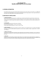
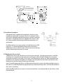
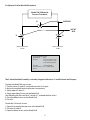
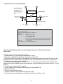
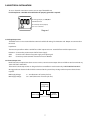
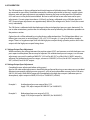
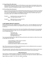
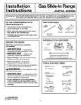
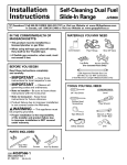
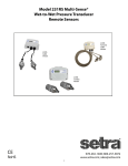
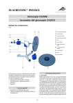
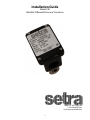
Installation Guide
Model 230
Wet/Wet Differential Pressure Transducer
1-800-257-3872 Toll Free
1-978-264-0292 Fax
www.setra.com Web Site
1
Table of Contents
1.0 General Information.......................................... 3
2.0 Mechanical Insallations.................................. 3
2.1 Media Compatibility................................................ 3
2.2 Environment.............................................................. 3
2.3 Pressure Fittings....................................................... 3
2.4 Moisture Precaustions............................................. 3
2.5 Mounting................................................................... 3
2.6 Installation Procedures........................................... 4
2.7 Bleeding the Pressure Ports................................... 4
2.8 Optional 3-Valve Manifold Procedure.................. 5
2.9 Optional 5-Valve Manifold Procedure.................. 6
3.0 ELECTRICAL INSTALLATION....................................... 7
3.1 Voltage Output Units............................................... 7
3.2 Current Output Units............................................... 7
4.0 CALIBRATION............................................................... 8
4.1 Voltage Output Zero Adjustment.......................... 8
4.2 Voltage Output Span Adjustment......................... 8
4.3 Current Output Zero Adjustment.......................... 9
4.4 Current Output Span Adjustment......................... 9
5.0 RETURN PRODUCTS FOR REPAIR.............................. 9
6.0 LIMITED WARRANTY AND LIMITATION OF LIABILITY
2
Setra Model 230
Wet/Wet Differential Pressure Transducer
1.0 GENERAL INFORMATION
Every Model 230 has been tested and calibrated before shipment. Setra Systems 230 pressure transducers sense differential
pressure and convert this difference in pressure to a proportional high level analog output. The 230 is supplied with either a
0 to 5 VDC or 0 to 10 VDC output or current output of 4 to 20 mA.
2.0 MECHANICAL INSTALLATION
2.1 Media Compatibility
Model 230 transducers are designed to be used with any gas or liquid compatible with 17-4 PH stainless steel, 300 series
stainless steel, and viton/silicone or Buna-n “O”-Rings. The optional 3-valve or 5-Valve manifold assembly is designed to be
used with gases or liquids compatible with 360 Brass, Acetal plug valves and Nitrile O-rings. Never totally submerge unit in
any liquids.
2.2 Environment
The operating temperature limits of the 230 are as follows:
Operating Temperature Range °F (°C) 0 to +175 (-18 to +80)
Compensated Temperature Range °F (°C) +30 to +150 (-1 to +65)
2.3 Pressure Fittings
Typically, standard pipe fittings and installation procedures should be used. The Model 230 has 1/4”-18 NPT internal fittings.
The high pressure port is labeled “HIGH”. The optional 3-valve and 5-valve manifold assembly is supplied with 1/4”-18 NPT
internal fittings.
2.4 Moisture Precautions
The Model 230 is provided with a 0.875 DIA. conduit opening for electrical termination, intended for a 1/2” I.D. conduit connection. This opening must be sealed according to standard industry practice in order to prevent moisture ingress into the
Model 230.
2.5 Mounting
The Model 230 is supplied with a mounting bracket and two 6-32 x 3/8 hex head screws. Attach bracket to mounting location first, using holes or band clamp notches available on large section of the bracket. Attach transducer to bracket by using
the two 6-32 x 3/8 hex head screws and the two tapped holes located on the underside of the transducer.
3
Top View
Transducer Mounting Holes
(screws provided: mounts to
bottom of 230 transducer)
0.875
22
f f
3.00
76 2.50
0.43
11
Conduit Opening
64
0.52
13
Notched for clamp mounting
0.88
22 1.30
33
0.156
.096
f f
Front View
1.50
38
1.63
41
in.
mm
2.6 Installation Procedures
If the Model 230 is supplied with an optional 3-valve or 5 valve
manifold assembly, refer to Section 2.8 and 2.9. Optional 3-Valve
and 5-Valve Manifold Assembly Procedure, for further installation
procedures. If the Model 230 is not supplied with a Setra 3-valve
or 5-valve manifold, the following installation procedure is recommended.
1.63
41
For differential pressure measurements at high line pressure (350
psig max.), it is recommended that the pressure sensor be installed with a valve in each line, plus a shunt valve across the high
and low reference pressure ports as shown.
Side View
With transducer
mounted to bracket
Low
High
Valve A
Valve B
Valve C
High
Low
Differential
Pressure Sensor
Valve A = High Side
Valve
Valve B = Low Side
Valve
Valve C = Shunt Valve
2.7 Bleeding the Pressure Ports
3 bleed screws are on the side of the unit (2 for low pressure port, 1 for high pressure port). Install the
transducer in its intended location and pressurize the ports. Back off the first bleed screw mounted
on the flat side of the sensor body (2 turns max.) until liquid begins to flow out. After only bubble-free
liquid flows out, retighten the bleed screw. Repeat same procedure for the second set of bleed screws
located on the round section of the low pressure fitting.
Valve C should be open and Valves A and B closed whenever the system is first being wetted or pressurized. Valves A and B should then be opened slowly to avoid hammering. Valve C can then be closed and
the system is operating.
When the differential pressure sensor is to be removed, Valve C must be opened first, then Valves A and
B can be closed.
4
2.8 Optional 3-Valve Manifold Procedure
Model 230 Differential
Pressure Transducer
V1
SHUNT VALVE
SHUT OFF
VALVE
V2
V2
High Process Connection
1/4” NPT
Low Process Connection
1/4” NPT
3-Valve Manifold Description
Manifold Block
Brass
Valves (3)
V1 for connection to ±port
V2 for connection to -port
V3 for equalizing pressure
Valve Type
90 Degree On/Off
Process Connection 1/4 ”-18 NPT Internal
Thread
The 3-Valve Manifold Assembly is normally shipped with valves V1 and V2 closed and V3 open.
To place the Model 230 into service:
1. Confirm valves V1 and V2 are closed and valve V3 is open.
2. Mount the manifold and install process connections.
3. Slowly open V2, then V1.
4. Slowly open bleed screws on the Model 230
(See “Bleeding the Pressure Ports”, section 2.7, to bleed the lines of air.)
5. Close the bleed screws on the Model 230
6. Close V3.
To take the 230 out of service:
1. Open V3 to equalize the pressure at the Model 230.
2. Close the V1 and V2.
3. Open the bleed screws on the Model 230.
5
2.9 Optional 5-Valve Assembly Procedure
Note: V6 and V7 bleed
valves are not required
when used with a
Setra Model 230. Use the
bleed screws on Model
230 to bleed the lines
of air.
V6
V7
Model 230
Differential Pressure Transducer
V3
V4
High Process/Commission
1/4”NPT Connection
V1
SHUNT VALVE
V5
Low Process/Commission
V2
SHUT OFF VALVES
Low Process Connection
1/4”NPT
High Process Connection
5-Valve Manifold Description
(Order as Pressure Code Fitting “5V” See Table below.)
Manifold Block
Brass
Valves (5)
V1 for connection to ±port
V2 for connection to -port
V3 for equalizing pressure
V4 for connection to external gauge or alternate plumbing configuration
V5 for connection to external gauge or alternate plumbing configuration
Valve Type
90 Degree On/Off
Process Connection 1/4 ”-18 NPT Internal Thread
The 5-Valve Manifold Assembly is normally shipped with valves V1, V2, V4, and V5 closed,
and V3 open.
To Place into service (Unit is mounted vertically):
1. Confirm valves V1, V2, V4, and V5 are closed and V3 is open.
2. Mount the manifold and install process connections to V1 and V2.
3. High Pressure Side: Slowly open V4 to bleed the air out of the high pressure side, close V4 when air stops
bleeding. Open the 2 bleed screws on the high pressure side of the Model 230, see Sec. 2.7, paragraph 1.
4. Install the pressure gauge on V4. Open V4.
5. Low Pressure Side: Slowly open V5 to bleed the air out of the low pressure side, close V5 when air stops
bleeding out. Open the bleed screw on the low pressure side of the Model 230 transducer, see Sec. 2.7, paragraph 1.
6. Install the pressure gauge on V5. Open V5.
7. System is bled, close V3 to apply differential pressure to the Model 230.
To take out of service:
1. Open V3 to equalize the pressure.
2. Close the V1 and V2 valves to disconnect pressure supply.
3. Slowly open the low and high pressure bleed ports to depressurize the system.
6
3.0 ELECTRICAL INSTALLATION
To access electrical connections remove cover on top of the Model 230
For CE compliance a shielded cable with both ends properly grounded is required.
For voltage output, use COM,OUT
and EXC terminals
For current (4-20 mA) output,
use + and - terminals
Diagram 1
3.1 Voltage Output Units
The Model 230 is a 3-wire circuit with three terminals available for wiring. The -Excitation and -Output are commoned on
the circuit.
Input Power
The 230 can operate from either 9-30 VDC for 0-5 VDC output version or 13-30 VDC for 0-10 VDC output version
Excitation Connected to positive terminal of DC Power Supply
COM
Connect as the reference for power supply and output signal
OUT
Connect to positive terminal of Control or Pressure Monitor
3.2 Current Output Units
Model 230 (current output) transducers are true 2-wire, 4-20 mA current output devices and deliver rated current into any
external load of 0-1000 ohms.
The 4-20 mA current output units are designed to have current flow in one direction only. PLEASE OBSERVE POLARITY.
We suggest that an electrical cable shield be connected to the system’s loop circuit ground to improve electrical noise
rejection.
MIN Supply Voltage:
MAX Supply Voltage:
9 + .02 x (Resistance of receiver plus line)
30 + .004 x (Resistance of receiver plus line)
Setra
Transmitter
(4-20 mA)
+
–
+
Power Supply
–
+
–
7
Load
(Monitor)
4.0 CALIBRATION
The 230 transducer is factory calibrated and should require no field adjustment. Whenever possible,
any zero and/or span offsets should be corrected by software adjustment in the user’s control system.
However, zero and span adjustments are made by removing the cover on the top of the 230 and the
6-32 seal screws in the plastic terminal block. Be sure to reinstall seal screws after zero and/or span
adjustments. Current output transducers (4-20 mA) are factory calibrated using a 250 ohm load at 24
VDC. Zero and span adjustments are approximately 300 mV (for voltage units) and ±1.0 mA (for current
units), individually.
The 230 Series is calibrated with the diaphragm in the vertical position (pressure ports horizontal). For
use in other orientations, position the unit and adjust the zero by following the calibration procedure in
the previous section.
Optimal results will be achieved by using the factory calibrated position. The 230 position effects is as
follows (pressure ports in vertical plane): ±.5D, ±1D, 1D, 2D ranges. ±1% per g for all other standard
ranges. There is a negative output shift with the high pressure port facing up and a positive shift in the
output with the high pressure port facing down.
4.1 Voltage Output Zero Adjustment
While monitoring the voltage between the positive output (OUT) and common, and with both pressure
ports open to atmosphere, the zero may be adjusted. For unidirectional pressure ranges, turn the zero
adjustment screw until a reading of 0.05 VDC (±25 mV for 0-5 VDC or ±50 mV for 0-10 VDC output) is
achieved. For bidirectional pressure ranges, set zero to 2.550 VDC (±25 mv) for 0-5 VDC output or 5.050
VDC (±50 mV) for 0-10 VDC output.
4.2 Voltage Output Span Adjustment
Complete the zero adjustment before setting span.)
Span or full scale output adjustments should only be performed by using an accurate pressure standard
(electronic manometer, digital pressure gage, etc.), with at least comparable accuracy to the 230 series
(±0.25% full scale). With the full range pressure applied to the high pressure port (reference open to
atmosphere), adjust output to 5.050 (±25 mV) or 10.050 VDC (±50 mV)
Example 1:
Unidirectional pressure range of 0 to 1 PSI
Apply 1 PSI, adjust output to 5.050 VDC (or 10.050 VDC)
Example 2:
Bidirectional pressure range of ±.5 PSI
Apply .5 PSI, adjust output to 5.050 VDC (for 10.050 VDC)
8
4.3 Current Output Zero Adjustment
While monitoring the current output, and with both pressure ports open to atmosphere, the zero may
be adjusted. For unidirectional pressure ranges, turn the zero adjustment screw until a reading of 4 mA
(±.08 mA) is achieved. For bidirectional ranges, set zero to 12 mA (±.08 mA).
4.4 Current Output Span Adjustment
Span or full scale output adjustments should only be performed by using an accurate pressure standard
(electronic manometer, digital pressure gage, etc.), with at leads comparable accuracy to the 230 series
(±.25% full scale). With full range pressure applied to the high pressure port (reference port open to
atmosphere), adjust span to achieve 20 mA (±0.08 ma) output.
Example 1:
Unidirectional pressure range of 0 to 1 PSI
Apply 1 PSI, adjust output to 20 mA
Example 2:
Bidirectional pressure range of ±.5 PSI
Apply .5 PSI, adjust output to 20 mA
5.0 RETURNING PRODUCTS FOR REPAIR
Please contact a Setra Systems application engineer (1-800-257-3872, 1-978-263-1400) before returning unit
for repair to review information relative to your application. Many times only minor field adjustments may
be necessary.
When returning a product to Setra Systems, the material should be carefully packaged and accompanied by
our service return form found at http://www.setra.com/uploads/service return form.pdf., completely filled
out, and shipped prepaid to:
Setra Systems, Inc.
159 Swanson Road
Boxborough, MA 01719-1304
Attn: Repair Department
To assure prompt handling, please supply the following information and include Service Return Form inside
the packaged returned materia:
1. Name and phone number of person to contact.
2. Shipping and billing instructions.
3. Full description of malfunction.
4. Identify any hazardous material used with product.
Notes: Please remove any pressure fittings and plumbing that you have installed and enclose any required
mating electrical connectors and wiring diagrams.
Allow approximately 3 weeks after receipt at Setra Systems for the repair and return of the unit. Non-warranty repairs will not be made without customer approval and purchase order to cover repair charges.
Calibration Services
Setra maintains a complete calibration facility that is traceable to the National Institute of Standards &
Technology (NIST). If you would like to recalibrate or recertify your Setra pressure transducers, please call our
Repair Department at 800-257-3872 (978-263-1400) for scheduling.
9
6.0 LIMITED WARRANTY AND LIMITATION OF LIABILITY
SETRA warrants its products to be free from defects in materials and workmanship, subject to the following terms and
conditions: Without charge, SETRA will repair or replace products found to be defective in materials or workmanship
within the warranty period; provided that:
a) the product has not been subjected to abuse, neglect, accident, incorrect wiring not our own, improper instal-
lation or servicing, or use in violation of instructions furnished by SETRA;
b) the product has not been repaired or altered by anyone except SETRA or its authorized service agencies;
c)
the serial number or date code has not been removed, defaced, or otherwise changed; and
d) examination discloses, in the judgment of SETRA, the defect in materials or workmanship developed under normal installation, use and service;
e) SETRA is notified in advance of and the product is returned to SETRA transportation prepaid.
Unless otherwise specified in a manual or warranty card, or agreed to in a writing signed by a SETRA officer, SETRA
pressure and acceleration products shall be warranted for one year from date of sale.
The foregoing warranty is in lieu of all warranties, express, implied or statutory, including but not limited to, any implied warranty of merchantability for a particular purpose.
SETRA’s liability for breach of warranty is limited to repair or replacement, or if the goods cannot be repaired or replaced, to a refund of the purchase price. SETRA’s liability for all other breaches is limited to a refund of the purchase
price. In no instance shall SETRA be liable for incidental or consequential damages arising from a breach of warranty,
or from the use or installation of its products.
No representative or person is authorized to give any warranty other than as set out above or to assume for SETRA any
other liability in connection with the sale of its products.
SS2010 Rev. J 4/4/14
For all CE technical questions, contact Setra Systems, USA. EU customers may contact our EU representative Hengstler
GmbH, Uhlandstr 48, 7854 Aldingen, Germany (Tel: +49-7424-890; Fax: +49-7424-89500)
159 Swanson Road, Boxborough, MA 01719-1304
Tel: 800-257-3872/978-264-1400
10
11
12