1
MOTOR
PROTECTION
ATCDIVERSIFIED.COM
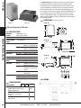
PRA-100-AFA
PRA-100-AFN
PRA-100-AFE
SLA-120-AFN
SLA-120-ALA
Motor-Driven Cycle Progress Timer
SLA-120-ALE
SLA-120-ALER
SLA-120-ASA
PHASE VOLTAGE MONITORS
SLA-120-ASB
SLA-208-AFN
SLA-220-AFN
SLA-230-ALA
SLA-230-ALE
SLA-230-ALER
SLA-230-ASA
SLA-230-ASB
SLA-240-AFN
SLA-380-ALE
SLA-380-ALER
SLA-380-ASA
SLA-440-AFE
SLA-440-ALE
SLA-440-ALER
SLA-440-ASA
SLA-460-AFE
SLA-480-AFE
SLA-575-AFE
SLA-575-ALE
SUA-120-ALA
SUA-120-ALAU
SUA-230-ALA
SUA-230-ALAU
SUA-380-ASA
SUA-440-ASA
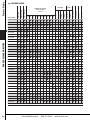
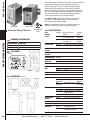
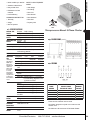
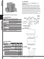
All models available with fixed operating voltages. Consult factory.
136
Diversified Electronics
800.727.5646
atcdiversified.com
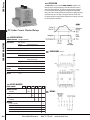
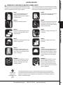
CSA Certified
UL Listed
UL Recognized
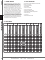
LED INDICATOR
MANUAL
AUTOMATIC
RESET
STYLE N
STYLE E
120 208 220 230 240 380 440 460 480 575
STYLE B
ENCLOSURE
NOMINAL LINE VOLTAGE
PHASE-TO-PHASE
50/60 HZ
STYLE A
PHASE SEQUENCE
UNDER VOLTAGE
MODEL NUMBER
PHASE LOSS
Feature Matrix
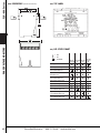
feature matrix
380
440
460
480
575
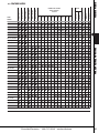
Feature Matrix
240
UL LISTED
230
CONTROL VOLTAGE
REQUIRED
220
LED INDICATOR
208
MANUAL
120
AUTOMATIC
RESET
NOMINAL LINE VOLTAGE
PHASE-TO-PHASE
50/60 HZ
STYLE E
ADJUSTABLE DELAY
PHASE SEQUENCE
PHASE UNBALANCE
OVER VOLTAGE
UNDER VOLTAGE
MODEL
NUMBER
PHASE LOSS
feature matrix
PBC-120-ALE
PBC-230-ALE
PBC-400-ALE
PBC-440-ALE
PBC-480-ALE
PBC-575-ALE
PBC-120/208-ALE
PBC-220/380-ALE
PBC-277/480-ALE
PHASE VOLTAGE MONITORS
PBD-120-ALE
PBD-230-ALE
PBD-400-ALE
PBD-440-ALE
PBD-480-ALE
PBD-575-ALE
PBE-120-ASE
PBE-230-ASE
PBE-400-ASE
PBE-440-ASE
PBE-480-ASE
PBE-575-ASE
PBE-120/208-ASE
PBE-220/380-ASE
PBE-277/480-ASE
SLB-200-ALEA*
SLB-200-ALER*
SLB-400-ALEA*
SLB-400-ALER*
SLC-120-ALE
SLC-230-ALE
SLC-380-ALE
SLC-440-ALE
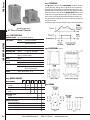
*The SLB Series is 60 Hz standard.
Diversified Electronics
800.727.5646
atcdiversified.com
137
SLD-120-ALE
SLD-120-ASA
SLD-230-ALE
SLD-230-ASA
Motor-Driven Cycle Progress Timer
SLD-380-ALE
SLD-380-ASA
SLD-440-ALE
PHASE VOLTAGE MONITORS
SLD-440-ASA
SLE-120-ALE
SLE-230-ALE
SLE-380-ALE
SLE-440-ALE
SLH-120-ALE
SLH-230-ALE
SLH-440-ALE
SLJ-120-ALE
SLJ-230-ALE
SLJ-380-ALE
SLJ-440-ALE
SLM-120-ASE
SLM-230-ASE
SLM-380-ASE
SLM-440-ASE
SLM-575-ASE
SLU-100-ASA
SLU-100-ASD
SLU-600-ASTDS
MPA-1000
MPA-1100
138
Diversified Electronics
800.727.5646
atcdiversified.com
CURRENT: OVER/UNDER/UNBAL.
CSA CERTIFIED
UL LISTED
UL RECOGNIZED
LED INDICATOR
MANUAL
AUTOMATIC
DIN RAIL/SURFACE MT.
DIN RAIL MOUNT
STYLE E (Surface Mount)
575
480
460
440
380
240
230
220
208
STYLE A (Plug-In)
RESET
NOMINAL LINE VOLTAGE
PHASE-TO-PHASE
50/60 HZ
120
ADJUSTABLE DELAY
PHASE SEQUENCE
FREQUENCY SHIFT
PHASE UNBALANCE
OVER VOLTAGE
UNDER VOLTAGE
MODEL NUMBER
PHASE LOSS
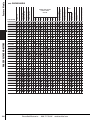
Feature Matrix
feature matrix
Feature Matrix
CSA CERTIFIED
UL RECOGNIZED
LED INDICATOR
STYLE N
STYLE E
STYLE A
440 VAC
240 VAC
230 VAC
ENCLOSURE
220 VAC
208 VAC
120 VAC
110 VDC
48 VDC
28 VDC
24 VDC
24 VAC
12 VDC
NOMINAL LINE VOLTAGE
ADJUSTMENT–FIXED
ADJUSTMENT–LOCKNUT
ADJUSTMENT–KNOB
OVER VOLTAGE
MODEL
NUMBER
UNDER VOLTAGE
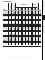
feature matrix
UOA-12-D*A
UOA-24-A*A
UOA-24-D*A
UOA-48-D*A
Motor-Driven Cycle Progress Timer
UOA-110-D*A
UOA-120-A*A
UOA-120-AFN
UOA-208-A*A
PHASE VOLTAGE MONITORS
UOA-208-AFN
UOA-220-AFN
UOA-230-AFN
UOA-240-A*A
UOA-240-AFN
VBA-12-D*A
VBA-24-A*A
VBA-24-AFN
VBA-24-D*A
VBA-28-D*A
VBA-48-D*A
VBA-110-D*A
VBA-120-A*A
VBA-120-AFN
VBA-208-A*A
VBA-208-AFN
VBA-220-AFN
VBA-230-AFN
VBA-240-A*A
VBA-240-AFN
Adjustments: F = Fixed, K = Knob, L = Locknut
Diversified Electronics
800.727.5646
atcdiversified.com
139
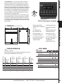
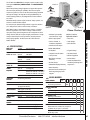
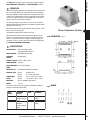
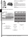
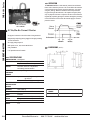
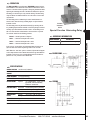
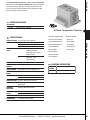
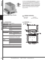
SLU-100 Series
Phase Monitor Relays (3-Phase Monitors) provide cost-effective protection
against premature equipment failure caused by voltage faults on 3-Phase systems (Wye or Delta). The SLU Series multi-mode phase monitoring relay, was designed for the convenience of electrician's, maintenance managers and engineers. A single SLU Phase Monitoring Relay can be easily adjusted for the voltage, imbalance percentage and time delay requirements to protect against unbalanced voltages or single phasing regardless of any regenerative voltages.
Both Delta and Wye systems may be monitored. In Wye systems,
connections to neutral are NOT required. The SLU-100 Series is UL Listed under UL File Number E55826.
SLU-100-ASA
NOTE: Not recommended for generator or variable frequency drive
applications. Call technical support for application assistance.
SLU-100-ASD
Universal Phase Monitor
IND. CONT. EQ
496Y
PHASE VOLTAGE MONITORS
ordering information
MODEL NUMBER DESCRIPTION
SLU-100-ASA
SLU-100-ASD
Universal Phase Monitor
Din Rail Mount Universal Phase Monitor
top labels
Plug-In
specifications
AUTO
RANGING
SCALES
Frequency
60Hz
50Hz
Nominal Line-to-Line
Voltages
208, 220, 240, 380, 415, 440, 460, 480
208, 220, 240
346, 380, 415
Adjustable
Range
200-250
360-500
200-250
330-430
VOLTAGE BAND
Drop-out
Pick-up
MAXIMUM
VOLTAGE
550 VAC (Line-to-Line)
PHASE
SEQUENCE
ABC (Will Not Operate On CBA Sequence)
±10% of Range Setting (Under/Over)
±7% of Range Setting (Under/Over)
POWER REQUIRED 90VA Max.
DIN Rail
dimensions
(inches)
PHASE
UNBALANCE
2% to 10%, Adjustable Drop-out
Hysteresis
10% of Setting
PHASE SHIFT
13° Drop-out, 12° Pick-up (Ø-Loss)
FREQUENCY
SHIFT
50/60 Hz
Drop-out
Pick up
RESET
Automatic or Manual Mode
RELAY OUTPUT
SPDT, 10A @ 240VAC Resistive, 1/2 HP @240VAC
INDICATORS
Normal
(Green LED)
Fault
(Red LED)
Flashing
Fault Delay Active
Restart Delay Active
RESPONSE
Power Up
Fault Delay
Severe Fault
Restart
2.5 SEC Minimum
.1 to 25 SEC., Adjustable
100mS (Phase-Loss, Unbalance or
Phase Reversal)
0.5 to 300 S, Adjustable (Auto Reset)
TEMPERATURE
RATINGS
Operate
Storage 32° to 131°F (0° to +55°C)
-49° to 185°F (-45° to +85°C)
± 4%
± 3%
Continuous
Relay
Energized
Relay
De-energized
REPEAT ACCURACY 1% @ Fixed Condition
TERMINALS (DIN) Slotted Screw Terminal Clamps, 12AWG Max.
140
Diversified Electronics
ENCLOSURE
Style “A”
DIN
WEIGHT
0.35 to 0.5 lbs.
800.727.5646
LEXAN® Dust Cover
35mm DIN Rail, 14 Term
Polycarbonate Housing
atcdiversified.com
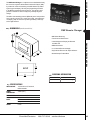
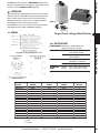
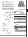
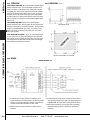
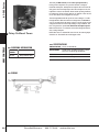
SLU-600 Series
The ATC-Diversified Electronics SLU-600-ASTDS Universal Phase Monitor protects
3-phase motors up to 700VAC. The Rapid Cycling feature prevents motors cycling due
to load-induced line fault conditions. Powered by 120VAC, this reliable motor protection
relay is unaffected by transients and disturbances from the monitored power source. The
SLU-600 Series is UL Listed under UL File Number E55826.
specifications
AUTO
RANGING
SCALES
Frequency
60Hz
50Hz
3Ø VOLTAGE
BAND
Drop-out
Pick-up
Nominal Line-to-
Line Voltages
208, 220, 240
380, 415, 440, 460, 480, 575, 600
208, 220, 240
346, 380, 415
Adjustable
Range
200-250
360-500
550-630
200-250
330-430
IND. CONT. EQ
496Y
Universal Phase Monitor
±10% of Range Setting (Under/Over)
±7% of Range Setting (Under/Over)
MAXIMUM VOLTAGE
700 VAC (Line-to-Line)
PHASE
SEQUENCE
ABC (Will Not Operate On CBA Sequence)
POWER REQUIRED 90VA Max.
PHASE
UNBALANCE
2% to 10%, Adjustable Drop-out
Hysteresis
10% of Setting
PHASE SHIFT
13° Drop-out, 12° Pick-up (Ø-Loss)
FREQUENCY
SHIFT
50/60 Hz
Drop-out
Pick up
RAPID CYCLING
5 Cycle Lockout, 30-Min. Cycle Count Reset
RESET
Automatic or Manual Mode
Clears Rapid Cycle Count
RELAY OUTPUT
DPDT, 10A @ 240 VAC Resistive
led's
Normal
(Green LED)
Fault (Red LED)
Over (Red LED)
Unbal / Ø Loss
(Red LED)
Flashing
Fault Delay
Active
Restart Delay
Active
Restart Delay
Active
Restart Delay
Active
RESPONSE
Power Up
Fault Delay
Severe Fault
Restart
2.5 S Minimum
0.1 to 25 S, Adjustable
100mS (Ø-Loss, Unbalance
or Ø Reversal)
0.5 to 300 S, Adjustable (Auto Reset)
TEMPERATURE
RATINGS
Operate
Storage 32° to 131°F (0° to +55°C)
-49° to 185°F (-45° to +85°C)
± 4%
± 3%
• Monitors up to 700 VAC
PROTECTS AGAINST:
• DIN Rail or Surface Mount
• Rapid Cycling
• Operating Range
200-630 VAC
• Phase Loss
• Manual or Automatic Reset
• Phase Unbalance
• Adjustable Restart Delay
• Phase Shift
• Adjustable Fault Delay
• Over/Under Voltage
Continuous
Relay
Energized
Relay
De-energized
Relay
De-energized
Relay
De-energized
• Phase Reversal
• Over/Under Frequency
PHASE VOLTAGE MONITORS
CONTROL VOLTAGE 120 VAC ±10%, 50/60Hz
ordering information
MODEL NUMBER DESCRIPTION
SLU-600-ASTDS
Universal Phase Monitor/Relay
REPEAT ACCURACY 1% @ Fixed Condition
TERMINALS
Plug and Socket Term Block with Spring Pressure Wire
Retention, 12 AWG Max.
ENCLOSURE
35mm DIN Rail or Surface Mount, Polycarbonate Housing
WEIGHT
1.10 lbs.
Diversified Electronics
800.727.5646
atcdiversified.com
141
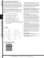
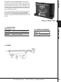
SLU-600 Series
(inches/millimeters)
PHASE VOLTAGE MONITORS
dimensions
top label
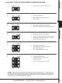
LED STATUS CHART
= OFF
= ON
= FLASHING
Unbal & Ø
Normal Under Red Over Red Loss Red
Green LED LED
LED
LED
Powering Up/First 3 Sec
Powered Up/Normal Voltages
Relay ON/Under Voltage
Detected/FAULT DELAY active
Relay ON/Over Voltage Detected/
FAULT DELAY active
Relay ON/Unbal or Ø Loss
Detected/FAULT DELAY active
Relay OFF/Under Voltage Failure
Relay OFF/Over Voltage Failure
Relay OFF/Unbal or Ø Loss Failure
Relay OFF/Under Voltage
Corrected/RESTART DELAY active
Relay OFF/Over Voltage
Corrected/RESTART DELAY active
Relay OFF/Unbal or Ø Loss
Corrected/RESTART DELAY active
142
Diversified Electronics
800.727.5646
atcdiversified.com
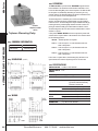
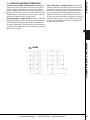
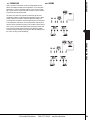
MPA Series
The MotorGuardianTM is a microprocessor based overload relay
designed to provide protection for 3-Phase AC motors. It offers a
broad range of features in one compact package providing a cost
effective solution for monitoring and managing motor performance.
Actual motor operating conditions are accessed by the scrolling menu
and viewed by a two line highly visible vacuum fluorescent display.
Fault conditions are also displayed indicating the specific cause of
the occurring fault. A unique feature of the The MotorGuardianTM is
its ease of installation. It is provided with Clamp-On C.T.'s that can
accommodate up to 1500 ampere loads.
There are two separate models that cover two input voltage ranges.
The Model MPA-1000 has a direct input voltage range of 200-500
VAC, 3-phase. The MPA-1100 has been designed to accept secondary volts from medium voltage transformers and has an input range
of 120-240VAC, 3-phase. The MPA Series is UL Listed under UL File
Number E55826.
“MOTORGUARDIANTM”
Motor Performance Analyzer
• Time Tagged Fault History
• Standard (200-500 VAC)
& Medium Voltage (20-240 VAC) • DPDT Output; SPDT Alarm
Versions
Output
(inches/millimeters)
• True RMS Monitoring
• Up to 1500 Amp Loads
• Bidirectional RS485 output
Modbus® RTU Protocol
• 3 External Clamp-On C.T.'s
• Built-in Real-Time Clock
• 9 Programmable Trip Points
• 2 x 16 Fluorescent Display
• 9 Programmable Alarm Points
• No Control Voltage Required
• 2 RTD Lead Compensated
Temperature Inputs
• All English Programming
(Scrolling Menu)
• Setpoint Change Lockout
MODEL NUMBER
ORDERING INFORMATION
Code
for
MPA
Part
No.
01A
02A
02B 03B 03C 04C 3 Required, 1 Per Phase
MODEL NUMBER
MPA
Order separately using SCT part numbers listed within chart or specify
which using Code for MPA Part No. at left of chart.
voltage
200-500 VAC
120-240 VAC
1000
1100
AMPS
1.5-15 A
15-150 A
150-600 A
600-1500 A
01
02
03
04
CT OPENING SIZE
0.75" Opening
1.25" Opening
2.0" Opening
Full Load
Amps/
Phase
0.75"
Opening
C.T. Part No.
1.25"
Opening
C.T. Part
No.
PHASE VOLTAGE MONITORS
dimensions
IND. CONT. EQ.
496Y
2.0"
Opening
C.T. Part No.
1.5 - 15A SCT-0750-015 -
-
15 - 150A
SCT-0750-150 -
15 - 150A SCT-1250-150 -
150 - 600A -
SCT-1250-600 150 - 600A -
SCT-2000-600
600 - 1500A -
SCT-2000-1500
Diversified Electronics
C.T.
Program
Code (Full
Scale
Amps.)
015
150
150
600
600
1500
800.727.5646
atcdiversified.com
A
B
C
143
MPA Series
specifications
PROGRAMMABLE TRIP/ALARM POINT
(Each setpoint can be disabled)
RELAY ACCURACY
Voltage Current G.F. Current Timing ±1%
±1%
±10%
5% ±1 Second
INPUT VOLTAGE
MPA-1000 MPA-1100 200-500 VAC 3-Phase (Nominal)
120-240 VAC 3-Phase ±20%
(Nominal)
FREQUENCY 50/60 Hz
PHASE SEQUENCE ABC (will not operate CBA)
PHASE VOLTAGE MONITORS
OUTPUT CONTACT DPDT; Form “C” 10A per pole max /
16 A Total @ 240 VAC
ALARM OUTPUT SPDT; Form “C” 7 A @ 240 VAC
COMMUNICATION
OUTPUT
RS485 Modbus RTU
BAUDRATE
2400 - 115 200
PARITY Even, None
WEIGHT 42 oz.
CT WEIGHTS
“A” size CT’s “B” size CT’s “C” size CT’s RESTART DELAY #2 Cool Down Timer; 0-999 Min., Active after over
current or unbalance fault.
RESTART DELAY #3 Dry Well Recovery; 0-999 Min., Active after
under current fault.
Over & Under Voltage, 0-99 Sec.
220-550V RMS
VOLTAGE
UNBALANCE
1-15%
CURRENT
UNBALANCE
1-15%
OVER CURRENT
Up to 100% of C.T. Range. Dependent on
C.T. Range, FLA, and Trip Class
GROUND FAULT 2 - 13% of CT Range
OVER TEMP. 1 1-250°C 3-wire 100 Ω Platinum Input or
2-wire with jumper
OVER TEMP. 2 1-250°C 3-wire 100 Ω Platinum Input or
2-wire with jumper
OVER CURRENT NEMA 5, 10, 15, 20, 30
TRIP CLASS J jam protection can be enabled for all classes
AUTO RESTART RESTART DELAY #1 Rapid Cycle Timer; 0-999 Sec
TRIP DELAY #2
HIGH VOLTAGE RESTART COUNTER
TIME DELAYS
Under Current, 0-99 Sec.
180-450V RMS
UNDER CURRENT Up to 100% of C.T. Range
4 oz.
11 oz.
25 oz.
TRIP DELAY #1 LOW VOLTAGE Number of Restarts, 0 (Manual),
1-8 or 9 (Automatic)
C.T. SPECIFICATIONS
ACCURACY 1%
TERMINATIONS
(2) 8ft. twisted pair, 22 AWG
MOUNTING Snap Closing/Opening Feature
TERMINAL DETAIL
144
Diversified Electronics
800.727.5646
atcdiversified.com
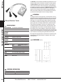
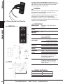
MGR-1000 Series
The MGR Remote Manager is a component of the MotorGuardian family
that is used in conjunction with the Motor Performance Analyzer (MPA ).
It provides full control and monitoring of the MPA functions by mimicking the keypad and display. The front panel programming is identical
to the MPA that simplifies the learning process. This external control
provides an efficient and safe tool away from potentially dangerous
voltages.
The MGR is environmentally protected (NEMA 4X) and is easily mounted
using a cutout on the front of a control panel or MCC. A vacuum fluorescent display (VFD) was selected to provide high visibility in both high
and low light situations.
DIMENSIONS (INCHES/MILLIMETERS)
MGR Remote Manager
• MPA Remote Monitoring
• Identical Keypad and Display as MPA-1000 and MPA-1100
• NEMA 4X Protection
• 2 x 16 Vacuum Fluorescent Display
• Polycarbonate Enclosure with Captive Hardware
• Removable Input Terminal Block
PHASE VOLTAGE MONITORS
• Total Control of MPA Functions
ORDERING INFORMATION
MODEL NUMBER DESCRIPTION
MGR-1000 MGR Remote Manager
specifications
INPUT VOLTAGE
115/230 VAC ±15% 50-60 Hz
Model Selectable
POWER CONSUMPTION
3 Watts (Max.)
ENVIRONMENT -10°C to +55°C NEMA 4X
COMMUNICATION
PORTS
RS485 Modbus RTU
Baudrate
2400 to 115200
Parity Even, None
WEIGHT 0.9 lbs
Diversified Electronics
800.727.5646
atcdiversified.com
145
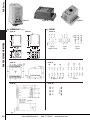
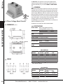
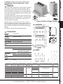
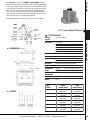
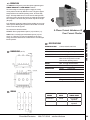
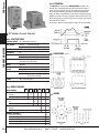
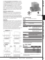
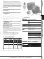
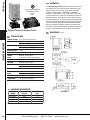
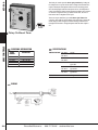
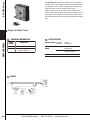
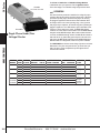
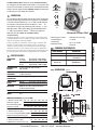
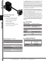
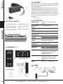
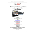
PRA Series
The PRA-100 Series Phase Sequence Monitors are designed to allow
the output to energize only when the phase connections are in the
proper sequence. For use in applications where motor direction is critical or the installation is required by code to have sequence detection.
When the phase sequence is correct and the operating voltage is present on all phases, the relay will energize and the green LED indicator will
glow. If the phases are in reverse rotation, the relay will not energize
and the red LED indicator will glow. The PRA-100 Series will not detect
phase loss while the motor is turning. The PRA Series is UL Listed under
UL File Number E55826.
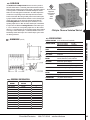
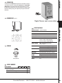
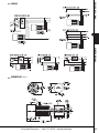
DIMENSIONS (INCHES/MILLIMETERS)
STYLE "A"
STYLE "N"
STYLE "A"
Phase Sequence Monitor
Style "N"
3.70"
3.225"
specifications
PHASE VOLTAGE MONITORS
OPERATING
VOLTAGE
208-480 VAC ±15%,
phase-to-phase, 50/60
2.18"
PHASE SEQUENCE ABC (Will Not Operate CBA)
Style "N"
.172" SLOT
STYLE
"N"
TOTAL APPARENT 11 VA @ 480 VAC
POWER
OUTPUT RATING
Style A & N Style E
RESET Automatic
INDICATORS
Green LED Red LED
3.70"
3.225"
.205"
SPDT, 10 Amps @ 240 VAC
Resistive, 1/2 hp @ 240 VAC
DPDT, 10 Amps @ 240 VAC
Resistive, 1/2 hp @ 240 VA
Glows on correct sequence
Glows on incorrect sequence
1.60"
.185"
2.18"
.172" SLOT
.205"
1.60"
STYLE "E"
RESPONSE TIMES 200 mSEC. (approximately)
.185"
TEMPERATURE RATING
Operate Storage 32° to +131°F (0° to +55°C)
-49° to 185°F (-45° to +85°C)
ENCLOSURE
Style “A” Style “N” Style “E” LEXAN® dust cover 8-Pin plug-in.
RB-08 or OT-08 Socket
Glass filled VALOX® surface
mounted 6-1/4" male quick connect
LEXAN® Surface Mount, #8-32 screws
WEIGHT
Style “A” Style “N” Style “E” 0.3 lbs.
0.35 lbs.
0.75 lbs
WIRING
MODEL NUMBER
MODEL NUMBER
PRA
ENCLOSURES
LEXAN® dust cover 8-Pin plug-in.
RB-08 or OT-08 Socket
Glass filled VALOX® surface mounted 6-1/4" male quick connect
LEXAN® Surface Mount, #8-32 screws
146
100
AFA AFN
AFE
Diversified Electronics
800.727.5646
atcdiversified.com
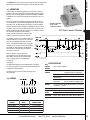
With normal operating voltages applied in the proper ABC sequence,
the internal relay will energize (PICK-UP). When incorrect phase
sequence or phase loss occurs or the three-phase voltages fall below
the drop out voltages, the relay will de-energize (DROP-OUT). On
models featuring indicators, the LED glows when all line conditions
are normal.
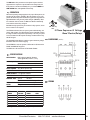
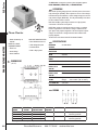
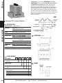
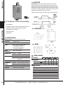
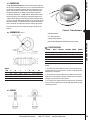
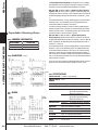
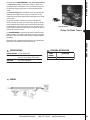
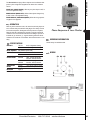
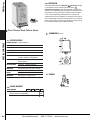
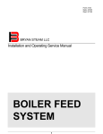
SLA Series
The ATC Diversified SLA Series is designed to protect 3-phase equipment against PHASE LOSS, UNDER VOLTAGE, and PHASE REVERSAL
conditions.
STYLE "A"
IND. CONT. EQ.
496Y
Both Delta and Wye systems may be monitored. In Wye systems, connections to neutral are NOT required.
NOTE: When a phase is lost while the motor is running, a condition
known as regeneration occurs where a voltage is induced into the
open phase nearly equal in magnitude to the normal phase-to-phase
voltage. However, with the exception of lightly loaded motors, enough
change is detected by the SLA to provide the required protection
when properly adjusted. The SLA Series is UL Listed under File Number E55826.
STYLE "E"
STYLE "N"
Phase Monitors
• Available up to 480 VAC
(625 VAC with "E" style)
PROTECTS 3-PHASE EQUIPMENT AGAINST:
• Delta or Wye Systems
• Phase Loss
• Fixed, Lock Shaft, or
Screwdriver Adjustment
• Under Voltage
specifications
DROP-OUT
VOLTAGE
1 Ø Low 3 Ø Low RESPONSE TIMES
STYLE “A” & “E”
Models Up to 300 VAC
Operate 250 mSEC
Release 0.5 SEC
Models Over 300 VAC
Operate 1.0 SEC
Release 2.0 SEC
TYPICAL APPLICATIONS:
83% of Nominal
90% of Nominal
• Air Handlers
• Irrigation Pumps
• Computer Power Protection
• Lift Station Pumps
• Conveyor Drive
• Robotics Equipment
• Water Waste & Sewage
Machinery
• Elevator Drives
• Commercial/Industrial Air
Conditioning & Refrigeration
• Sawmill & Woodpump Machinery Compressors
• Oil & Gas Pumps
RESPONSE TIMES Operate STYLE “N”
Release 60 mSEC
0.5 SEC
POWER
REQUIRED
Style “A” Style “E”
Style “N” 3 VA (approx.)
Models up to 300 VAC: 3 VA (max.)
Models over 300 VAC: 7 VA (max.)
Models over 500 VAC: 3 VA (max.)
3 VA (max.)
OPERATING
VOLTAGE
See Ordering Information
RESET Automatic (Manual Optional)
INDICATOR LED
Glows when all conditions are Normal
(On Applicable Models)
OUTPUT RATING SPDT (style “A” and “N”)
DPDT (style “E”)
• Power Substation
• Automatic Transfer Switching for
Monitoring Emergency Power
Supplies
MODEL NUMBER
MODEL NUMBER
Operate Storage U.S. PATENT
NUMBER
3,611,050
WEIGHT
Style “A” Style “E” Style “N” Type of Operation
Fixed
Lock Shaft Adjusted
Screwdriver Adjusted 32° to +131°F (0° to +55°C)
-49° to 185°F (-45° to +85°C)
NET: 2.24 oz Shipping: 2.56 oz
NET: 4.8 oz Shipping: 5.76 oz
NET: 5.3 oz Shipping: 5.6 oz
Diversified Electronics
SLA
A
F
L
S
Operating Voltage
See Ordering Information XXX
PHASE SEQUENCE ABC (Will Not Operate CBA)
TEMPERATURE
RATING
• Phase Reversal
• Several Enclosure Styles
PHASE VOLTAGE MONITORS
For UL Listed units, with field wiring terminals, copper wire with 60°/
75°C rating must be used for control circuitry connections.
Enclosure Style
Octal Plug-In, Dust Cover Blade Plug-In, Dust Cover Surface Mounted, #8 Screw Terminals Surface Mounted, 1/4" Quick Disconnect Terminals Options
Add R Suffix when manual reset is required,
(available only in style “E” enclosure)
Plug-In models are UL listed only when used with
RB-08 relay socket.
800.727.5646
atcdiversified.com
A
B
E
N
R
U
147
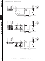
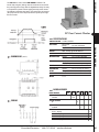
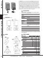
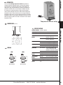
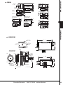
SLA Series
DIMENSIONS (INCHES)
PHASE VOLTAGE MONITORS
STYLE "A"
STYLE "E"
STYLE "N"
STYLE "A"
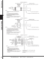
wiring
STYLE "b"
STYLE "A"
Figure 1
RB-08 or OT-08
Figure 2
RB-11
2.375"
1.75"
Style B
STYLE "E"
STYLE "E"
Figure 4
STYLE "n"
148
Figure 3
70-463-1
STYLE "n"
Diversified Electronics
800.727.5646
atcdiversified.com
Figure 5
STYLE A PLUG-IN
OPERATING
VOLTAGE
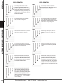
SLA-120-ALA
SLA-120-ASA
95-130 Adj
SLA-230-ALA
SUA-120-ALA
SUA-120-ALAU*
SUA-230-ALA
SUA-230-ALAU*
SUA-380-ASA
SUA-440-ASA
AGENCY
APPROVAL
Screwdriver
—
79-108
85-117
—
Lock Shaft
190-270 Adj.
SLA-230-ASB
SLA-380-ASA
SLA-440-ASA
DROP-OUT VOLTAGE
1 Ø LOW
3 Ø LOW
Lock Shaft
SLA-120-ASB
SLA-230-ASA
TYPE OF
ADJUSTMENT
158-224
171-243
—
Screwdriver
350-440 Adj.
430-480 Adj.
290-365
378-461
315-396
410-500
95-130 Adj.
79-108
85-117
Lock Shaft
190-270 Adj.
350-440 Adj.
430-480 Adj.
Screwdriver
158-224
171-243
290-365
410-500
315-396
410-500
—
IND.
CONT. EQ
496Y
OUTPUT RATINGS
DPDT, 345 VA Inductive; 10 Amps
Resistive @ 240 VAC. Figure 2
SPDT, 345 VA Inductive; 10 Amps
Resistive @ 240 VAC, Figure 1
SPDT, 345 VA Inductive; 10 Amps
Resistive @ 240 VAC, Figure 3
DPDT, 345 VA Inductive; 10 Amps
Resistive @ 240 VAC, Figure 2
SPDT, 345 VA Inductive; 10 Amps
Resistive @ 240 VAC, Figure 1
SPDT, 345 VA Inductive; 10 Amps
Resistive @ 240 VAC, Figure 3
SPDT, 360 VA Inductive; 10 Amps
Resistive @ 240 VAC, Figure 1
SPDT, 345 VA Inductive; 10 Amps
Resistive @ 240 VAC, Figure 1
IND.
CONT. EQ
496Y
SPDT, 360 VA Inductive; 10 Amps
Resistive @ 240 VAC, Figure 1
*UL Listed only when used with RB-08 relay socket; 5 Amps Resistive @ 240 VAC. All voltages referenced on this page are phase-to-phase.
Models also available with fixed operating voltages. Consult factory.
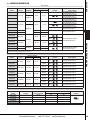
STYLE E SURFACE MOUNTED ENCLOSURE
MODEL
NUMBER
SLA-120-ALE
SLA-120-ALER
SLA-230-ALE
SLA-230-ALER
SLA-380-ALE
SLA-380-ALER
SLA-440-ALE
SLA-440-ALER
SLA-575-ALE
OPERATING
VOLTAGE
DROP-OUT VOLTAGE
1 Ø LOW
3 Ø LOW
95-130 Adj.
190-270 Adj.
79-108
158-224
85-117
171-243
350-440 Adj.
290-365
315-396
430-480 Adj.
357-398
387-432
525-625 Adj.
436-519
473-563
AGENCY
APPROVAL
RESET
Automatic
IND.
CONT. EQ
496Y
Manual
IND.
CONT. EQ
496Y
Automatic
IND.
CONT. EQ
496Y
Manual
IND.
CONT. EQ
496Y
Automatic
IND.
CONT. EQ
496Y
Manual
IND.
CONT. EQ
496Y
Automatic
IND.
CONT. EQ
496Y
Manual
IND.
CONT. EQ
496Y
Automatic
IND.
CONT. EQ
496Y
OUTPUT RATINGS
DPDT, 211 VA Inductive; 10 Amps
Resistive @ 120 VAC. Figure 4
DPDT, 211 VA Inductive; 10 Amps
Resistive @ 120 VAC. Figure 4
DPDT, 345 VA Inductive; 5 Amps
Resistive @ 240 VAC. Figure 4
DPDT, 345 VA Inductive; 5 Amps
Resistive @ 240 VAC. Figure 4
DPDT, 360 VA Inductive; 3 Amps
Resistive @ 600 VAC. Figure 4
SPDT, 360 VA Inductive; 3 Amps
Resistive @ 600 VAC. Figure 5
DPDT, 360 VA Inductive; 3 Amps
Resistive @ 600 VAC. Figure 4
SPDT, 360 VA Inductive; 3 Amps
Resistive @ 600 VAC. Figure 5
DPDT, 360 VA Inductive; 3 Amps
Resistive @ 600 VAC. Figure 4
PHASE VOLTAGE MONITORS
MODEL
NUMBER
SLA Series
ORDERING INFORMATION
All voltage referenced are phase-to-phase.—Models also available with fixed operating voltages. Consult factory.
STYLE N EPOXY ENCAPSULATED
MODEL
NUMBER
SLA-120-AFN
SLA-208-AFN
SLA-220-AFN
SLA-240-AFN
OPERATING
VOLTAGE
120
208
220
240
TYPE OF OPERATION
DROP-OUT VOLTAGE
1 Ø LOW
3 Ø LOW
Fixed
Fixed
Fixed
Fixed
100
173
183
199
AGENCY
APPROVAL
108
187
198
216
All voltage referenced are phase-to-phase.
Diversified Electronics
800.727.5646
atcdiversified.com
149
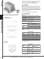
PBC Series
The PBC Series offers protection to three-phase equipment that is
required to operate between two voltage limits. All three phases are
monitored individually for a pre-selected under and over voltage
limit.
operation
With normal operating voltages applied, the internal relay will energize
(PICK-UP). When the voltages on any or all phases fall outside the preset Over/Under trip points for longer than the Release delay, the relay
will de-energize (DROP-OUT). When line conditions return to normal, the
PBC Series Monitor automatically resets and the internal relay energizes.
IND. CONT. EQ 496Y
3-Phase Voltage Band Monitor
DIMENSIONS (INCHES)
The LED fault indicators aid in set up and system trouble-shooting glowing on fault condition. The LED indicators have an immediate response
to voltage conditions and operate independently of the relay.
The HYSTERESIS in each unit provides a differential of 4% between the
PICK-UP and DROP-OUT trip points.
The PBC Series is UL Listed under UL File Number E55826.
SPECIFICATIONS
PHASE VOLTAGE MONITORS
OUTPUT RATING
DPDT, 3 Amps @ 600 VAC, Resistive;
360 VA @ 600 VAC, Inductive; 1/2 hp
POWER REQUIRED Models Up to 300 VAC
Models Over 300 VAC
RESET
Automatic
HYSTERESIS
4%
7 VA, Max
6 VA, Max
REPEAT ACCURACY 0.1% @ Fixed Condition
INDICATORS LED
Glows On Fault; (1) For Over, (1) For Under
RESPONSE TIMES Operate
Release
100 mSEC
0.5 SEC
TEMPERATURE
RATING
Operate Storage 32° to +131°F (0° to +55°C)
-49° to 185°F (-45° to +85°C)
WEIGHT 20 oz.
MODEL
NUMBER
DELTA CONNECTED
MAXIMUM
ADJUSTABLE RANGES
VOLTAGEUNDER OVER
PBC-120-ALE
155 VAC
90-120 120-150
PBC-230-ALE 275 VAC 185-240 208-265
PBC-400-ALE 485 VAC 325-385 415-475
PBC-440-ALE 550 VAC 390-480 440-540
PBC-480-ALE 570 VAC 400-490 460-560
PBC-575-ALE 700 VAC 500-610 540-690
All voltages referenced on this page are phase-to-phase, unless otherwise indicated.
WIRING
WYE CONNECTED
MODEL
MAXIMUM
ADJUSTABLE RANGES
NUMBER
VOLTAGE
(Phases to Neutral)
UNDER OVER
PBC-120/208-ALE 268 VAC 90-120
120-150
PBC-220/380-ALE 450 VAC 185-220 220-255
PBC-277/480-ALE 565 VAC 235-277 277-320
All voltages referenced on this page are phase-to-phase, unless
otherwise indicated.
150
Diversified Electronics
800.727.5646
atcdiversified.com
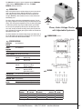
PBD Series
The PBD Series offers protection to three-phase sequence sensitive
equipment that is required to operate between two voltage limits. All
three phases are monitored individually for a pre-selected Under and
Over voltage limit, with adjustable release delay.
operation
With normal operating voltages applied in the proper ABC sequence, the
internal relay will energize (PICK-UP). When the voltages on any or all
phases fall outside the preset Over/Under trip points for longer than the
Adjustable Release delay, the relay will de-energize (DROPOUT). When
line conditions return to normal, the PBD Series Monitor automatically
resets and the internal relay energizes.
The LED fault indicators aid in set up and system troubleshooting, and
glow on fault condition. The LED indicators have an immediate response
to voltage conditions and operate independently of the relay. In a phase
reversal condition the LED responds to voltage conditions but the relay
will NOT energize.
The Adjustable Release Delay is provided to ignore momentary voltage
fluctuations that cause nuisance tripping.
IND. CONT. EQ 496Y
3 Phase Sequence & Voltage
Band Monitor/Relays
DIMENSIONS (INCHES)
PHASE VOLTAGE MONITORS
Both Delta and Wye systems may be monitored. In Wye systems, connections to neutral are not required.
The HYSTERESIS in each unit provides a differential of 4% between the
PICK-UP and DROP-OUT trip points.
The PBD Series is UL Listed under UL File Number E55826.
SPECIFICATIONS
OUTPUT RATING
DPDT, 3 Amps @ 600 VAC, Resistive;
360 VA @ 600 VAC, Inductive; 1/2 hp
POWER REQUIRED Models Up to 300 VAC
Models Over 300 VAC
RESET
7 VA, Max
6 VA, Max
Automatic
PHASE SEQUENCE ABC (Will Not Operate CBA)
HYSTERESIS
4%
REPEAT ACCURACY 0.1% @ Fixed Condition
INDICATORS LED
Glows On Fault; (1) For Over, (1) For Under
RESPONSE TIMES Operate
Release
100 mSEC
0.1 to 30 SEC, Adjustable
TEMPERATURE
RATING
Operate Storage 32° to +104°F (0° to +40°C)
-49° to 185°F (-45° to +85°C)
WEIGHT 19 oz.
MODEL
NUMBER
WIRING
MAXIMUM
ADJUSTABLE RANGES
VOLTAGEUNDER OVER
PBD-120-ALE 155 VAC
90-120 120-150
PBD-230-ALE 275 VAC 185-240 208-265
PBD-400-ALE 485 VAC 325-385 415-475
PBD-440-ALE 550 VAC 390-480 440-540
PBD-480-ALE 570 VAC 400-490 460-560
PBD-575-ALE 700 VAC 500-610 540-690
All voltages referenced on this page are phase-to-phase.
Diversified Electronics
800.727.5646
atcdiversified.com
151
PBE Series
In today’s industrial environment, Line Noise and Power Line Harmonics
are becoming an increasing problem. True-RMS detection may be
necessary for achieving accurate Line Voltage measurement.
operation
With normal operating voltages applied in the proper ABC sequence, the
internal relay will energize (PICK-UP). When the voltages on any or all
phases fall outside the preset Over/Under trip points for longer than the
Drop-Out Time delay, the relay will de-energize (DROP-OUT). When line
conditions return to normal, the PBE Series Monitor automatically resets
and the internal relay energizes.
IND. CONT. EQ 496Y
True RMS Voltage Band Monitor
DIMENSIONS (INCHES)
The PBE Series is UL Listed under UL File Number E55826.
SPECIFICATIONS
OUTPUT RATING
DPDT, 10 Amps Resistive, 1/4 HP @ 240 VAC
RESET
Automatic
PHASE SEQUENCE ABC (Will Not Operate CBA)
HYSTERESIS 2%
PHASE VOLTAGE MONITORS
REPEAT ACCURACY 0.1% @ Fixed Condition
INDICATORS LED Glows On Fault; (1) For Over, (1) For Under,
(1) For Sequence
RESPONSE TIMES Operate Release 200 mSEC (approx.)
0.2 to 30 SEC, Adjustable
TEMPERATURE RATING
Operate Storage 32° to +104°F (0° to +40°C)
-49° to 185°F (-45° to +85°C)
ENCLOSURE Style “E” LEXAN® Surface Mount
WEIGHT 14 oz.
MODEL
NUMBER
DELTA CONNECTED
MAXIMUM
ADJUSTABLE RANGES
VOLTAGEUNDER OVER
PBE-120-ASE 155 VAC 90-120 120-150
PBE-230-ASE 275 VAC 185-240 208-265
PBE-400-ASE 485 VAC 325-385 415-475
PBE-440-ASE 550 VAC 390-480 440-540
PBE-480-ASE 570 VAC 400-490 460-560
PBE-575-ASE 700 VAC 500-610 540-690
All voltages referenced on this page are phase-to-phase, unless otherwise indicated.
WIRING
WYE CONNECTED
MODEL
MAXIMUM
ADJUSTABLE RANGES
NUMBER
VOLTAGE
(Phase to Neutral)
UNDER OVER
PBE-120/208-ASE 160 VAC, P to N
90-120 120-150
277 VAC, P to P
PBE-220/380-ASE 260 VAC, P to N
185-220 220-255
450 VAC, P to P
PBE-277/480-ASE 326 VAC, P to N
235-277 277-320
565 VAC, P to P
All voltages referenced on this page are phase-to-phase, unless otherwise indicated.
152
Diversified Electronics
800.727.5646
atcdiversified.com
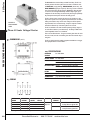
SLB Series
The SLB Series is designed to protect three-phase equipment against
Phase Unbalance, Phase Loss, and Phase Reversal conditions.
operation
With normal operating voltages in the proper ABC sequence and the 120
VAC control voltage applied, the internal relay will energize (PICK-UP).
When any combination of Phase Unbalance exceeding the preset value
or Phase Loss or Phase Reversal occurs for longer than the preset drop
out time, the output relay will de-energize (DROP-OUT). If the control
voltage is removed, the relay will de-energize.
The wide input voltage range permits use on any one of several standard line voltages without recalibrating. The unbalance detection level is
adjustable from 2% to 15%.
Both Delta and Wye systems may be monitored. In Wye systems, connections to neutral are not required.
Phase Unbalance Monitor
The LED indicator glows when conditions are normal.
DIMENSIONS (INCHES)
PHASE VOLTAGE MONITORS
NOTE: A balanced condition exists and the output relay will energize
when there is a complete absence of voltage on all three phases (Terminals 1, 3 and 5) and the control voltage is continuously applied to
(Terminals 11 and 12). For this reason, the SLB series is ideally suited
for load side monitoring applications.
SPECIFICATIONS
OUTPUT RATING
SPDT, 10 Amps @ 120 VAC,
5 Amps @ 240 VAC, Resistive
PHASE SEQUENCE ABC (Will Not Operate CBA)
OPERATING VOLTAGE
See Table Below
CONTROL VOLTAGE 120 VAC, 1 Phase, 60 Hz
POWER REQUIRED 3 VA, Max.
PHASE UNBALANCE 2% to 15%, Adjustable
RANGE
INDICATORS LED
Glows When All Conditions Are Normal
RESPONSE TIMES Operate Release 60 mSEC, Fixed
0.1 to 5 SEC, Adjustable
TEMPERATURE RATING
Operate Storage 32° to +104°F (0° to +40°C)
-49° to 185°F (-45° to +85°C)
ENCLOSURE Style “E” LEXAN® Surface Mount
WEIGHT 1 lb. 2 oz.
The SLB Series will not detect an equal and simultaneous reduction in
voltage on all three lines (Brown Out).
MODEL
NUMBER
OPERATING
VOLTAGE
RESET WIRING
HYSTERESIS
SLB-200-ALEA Standard 0-300; Automatic 10% of Unbalance
3 Ø Line Voltages Setting
SLB-200-ALER 60 Hz.
Manual
None
SLB-400-ALEA Standard
Automatic 10% of Unbalance
300-500;
Setting
3 Ø Line Voltages
60 Hz
All voltages referenced on this page are phase-to-phase.
Diversified Electronics
800.727.5646
atcdiversified.com
153
SLC Series
The SLC Series is designed to protect 3-phase equipment against Phase
Unbalance and Phase Loss conditions.
operation
With normal operating voltages applied to all three phases, the internal
relay will remain de-energized (DROPPED-OUT).
When a Phase Loss or Phase Unbalance exceeding the pre-selected trip
point occurs, the relay will energize (PICK-UP). The SLC series is typically used in conjunction with a shunt trip breaker.
Both Delta and Wye systems may be monitored. In Wye systems, connections to neutral are not required.
Phase Unbalance & Loss Monitor
PHASE VOLTAGE MONITORS
DIMENSIONS (INCHES)
NOTE: When a phase is lost while the motor is running, a condition
known as regeneration occurs where a voltage is induced into the open
phase nearly equal in magnitude to the normal phase-to-phase voltage. The SLC series is designed to detect this condition when properly
adjusted.
SPECIFICATIONS
OPERATING VOLTAGE
See Table Below
TRANSIENT
PROTECTION
1000 Volts For 8 mSEC
RESET Automatic
PHASE UNBALANCE 2% to 10%, Adjustable
RANGE
WIRING
INDICATORS LED Glows On Fault Condition
RESPONSE TIMES
Operate Release 0.08 SEC
0.7 SEC
TEMPERATURE RATING Operate Storage 32° to +131°F (0° to +55°C)
-49° to 185°F (-45° to +85°C)
U.S. PATENT
NUMBER
4,331,995
WEIGHT 12.5 oz.
MODEL
NUMBER
OPERATING
VOLTAGE
POWER
OUTPUT
REQUIRED RATING
SLC-120-ALE SLC-230-ALE SLC-380-ALE SLC-440-ALE 120 VA
208/240 VAC
380 VAC
440/480 VAC
3 VA
Max.
7 VA
Max.
DPDT, 5 Amps,
Resistive;
345 VA, Inductive
@ 240 VAC
DPDT, 3 Amps, Resistive;
360 VA, Inductive
@ 600 VAC
All voltages referenced on this page are phase-to-phase.
154
Diversified Electronics
800.727.5646
atcdiversified.com
SLD Series
The SLD Series is designed to protect 3-phase equipment against
Phase Unbalance, Phase Loss, Under Voltage and Phase
Reversal conditions.
operation
With normal operating voltage present on all three phases in the proper
phase sequence, the internal relay will energize (PICK-UP). When an
incorrect phase sequence or phase loss occurs or the three-phase line
voltages fall outside the preset unbalance or under voltage settings, the
internal relay will de-energize (DROP-OUT). When all conditions return
to normal, the relay will reset.
The Adjustable Release Delay is provided to ignore momentary voltage
fluctuations that cause nuisance tripping. 20% or > instantaneous trip
Both Delta and Wye systems may be monitored. In Wye Systems, connections to neutral are not required.
NOTE: When a phase is lost while the motor is running, a condition
known as regeneration occurs where a voltage is induced into the open
phase nearly equal in magnitude to the normal phase-to-phase voltage. The SLD series is designed to detect this condition when properly
adjusted.
STYLE "E"
STYLE "a"
IND. CONT. EQ.
496Y
Phase & Under Voltage Monitor
DIMENSIONS (INCHES)
SPECIFICATIONS
OPERATING VOLTAGE
See Table Below
TRANSIENT
PROTECTION
1000 Volts For 8 mSEC
RESET Automatic
PHASE SEQUENCE
ABC (will not operate CBA)
PHASE UNBALANCE 2% to 10%, Adjustable
RANGE
STYLE "a"
INDICATORS LED Glows When All Conditions Are Normal
RESPONSE TIMES
Operate Release 30 mSEC
0.1 to 20 SEC, Adjustable (on
Under Voltage only); 100 mSEC on
Phase Reversal and Unbalance
TEMPERATURE RATING Operate Storage 32° to +131°F (0° to +55°C)
-49° to 185°F (-45° to +85°C)
U.S. PATENT
NUMBER
4,331,995
WEIGHT 13.5 oz.
STYLE "E"
WIRING
MODEL
OPERATINGUNDER VOLTAGE
NUMBERvoltage
DROPOUT RANGE
POWER
REQUIRED
HYSTERESIS
SLD-120-ASA 120 VAC 95-115 Adj.
SLD-230-ASA 208/240 VAC 185-230 Adj.
SLD-380-ASA 380 VAC 315-390 Adj.
SLD-440-ASA 440/480 VAC 370-460 Adj.
SLD-120-ALE 120 VAC 95-115 Adj.
SLD-230-ALE 208/240 VAC 185-230 Adj.
SLD-380-ALE 380 VAC 315-390 Adj.
SLD-440-ALE 440/480 VAC 370-460 Adj.
All voltage referenced are phase-to-phase.
3 VA Max.
2.5 VAC
5.0 VAC
10 VAC
SPDT, 10 Amp, Resistive @ 240 VAC
1/2 HP @ 240 VAC
A
7 VA Max
5 VAC
10 VAC
DPDT, 5 Amps, Resistive; 345 VA,
Inductive @ 240 VAC
DPDT, 3 Amps, Resistive; 360 VA,
Inductive @ 600 VAC
E
Diversified Electronics
PHASE VOLTAGE MONITORS
The SLD Series is UL Listed under UL File Number E55826.
800.727.5646
OUTPUT RATINGenclosure
atcdiversified.com
155
SLE Series
The SLE Series is designed to protect 3-phase equipment against
Phase Unbalance, Phase Loss, and Under Voltage.
operation
With normal operating voltage present on all three phases, the internal
relay will energize (PICK-UP). When a phase loss occurs or the voltages
fall outside the preset unbalance or under voltage settings, the internal
relay will de-energize (DROP-OUT). The relay automatically resets when
the line conditions return to normal.
Both Delta and Wye systems may be monitored. In Wye Systems, connections to neutral are not required.
PHASE VOLTAGE MONITORS
Phase Monitor
NOTE: When a phase is lost while the motor is running, a condition
known as regeneration occurs where a voltage is induced into the open phase nearly equal in magnitude to the normal phase-to-phase voltage. The SLE series is designed to detect this condition when properly adjusted.
IND. CONT. EQ.
496Y
• Models Available up to 480 VAC
LOCK SHAFT ADJUSTMENT FOR:
PROTECTS 3-PHASE EQUIPMENT AGAINST:
• Under Voltage Drop Out
• Phase Loss
• Under Voltage
The SLE Series is UL Listed under UL File Number E55826
SPECIFICATIONS
• Phase Unbalanced Percent
• Automatic Reset
• Delta or Wye Systems
• Phase Unbalance
OPERATING VOLTAGE
See Table Below
TRANSIENT
PROTECTION
1000 Volts For 8 mSEC
RESET Automatic
PHASE UNBALANCE 2% to 10%, Adjustable
RANGE
DIMENSIONS
(INCHES)
INDICATORS LED Glows When All Conditions Are Normal
RESPONSE TIMES
MODELS UP TO
300 VAC
Operate Release 60 Milliseconds
0.5 Seconds
RESPONSE TIMES
MODELS OVER
300 VAC
Operate Release 1 Second
2 Seconds
TEMPERATURE RATING Operate Storage 32° to +131°F (0° to +55°C)
-49° to 185°F (-45° to +85°C)
U.S. PATENT No.
4,331,995
WEIGHT 12.5 to 13 oz.
WIRING
156
MODEL
OPERATINGUNDER VOLTAGE
NUMBERvoltage
DROPOUT RANGE
POWER
REQUIRED
HYSTERESIS
OUTPUT RATING
SLE-120-ALE 120 VAC 95-115 Adj.
SLE-230-ALE 208/240 VAC 185-230 Adj.
SLE-380-ALE 380 VAC 315-390 Adj.
SLE-440-ALE 440/480 VAC 370-460 Adj.
All voltage referenced are phase-to-phase.
3 VA Max.
7 VA Max. 5.0 VAC
10 VAC DPDT, 5 Amps, Resistive; 345 VA,
Inductive @ 240 VAC
DPDT, 3 Amps, Resistive; 360 VA,
Inductive @ 600 VAC
Diversified Electronics
800.727.5646
atcdiversified.com
SLH Series
The SLH Series is designed to protect equipment against PHASE LOSS
(single phasing), UNDER VOLTAGE (brown outs), and PHASE
REVERSAL (improper sequence).
operation
When correct phase sequence and line voltage are present, the internal
relay of the SLH will energize (PICK UP). When there is a phase loss,
under voltage or phase reversal condition, the internal relay will deenergize (DROP-OUT). When conditions return to normal, the SLH will
automatically reset.
IND. CONT. EQ.
496Y
The SLH is available in the standard voltage ranges (see table below). It
has an LED indicator that glows when all conditions are normal. The SLH
Series is UL Listed under UL File Number E55826.
Phase, Under Voltage Monitor
with Adjustable Hysteresis
DIMENSIONS (INCHES)
PHASE VOLTAGE MONITORS
The SLH is unique in that it has a field-adjustable hysteresis. The voltage setting is adjusted to the desired pick-up point indicated by the dial
setting. Then, the hysteresis adjustment is set to the desired percentage
to achieve the preferred drop-out point. When models up to 300 VAC
are set at 0%, they will pick-up and drop-out at the same point, when
set at 10%, the drop-out will be an average of the phase-to-phase voltages 10% below the dial setting pick-up point. Models over 300 VAC are
adjustable from 0% to 15%.
SPECIFICATIONS
OPERATING VOLTAGE
See Table Below
POWER REQUIRED
See Table Below
RESET Automatic
PHASE SEQUENCE ABC (Will Not Operate CBA)
HYSTERESIS
Models Up to
300 VAC
Models Over
300 VAC
Adjustable, 0% to 10%
Below Pick-up
Adjustable, 0% to 15%
Below Pick-up
OUTPUT RATING
Models Up to
300 VAC
Models Over
300 VAC
DPDT, 10 Amps @ 120 VAC,
Resistive; 211 VA @ 120 VAC, Inductive
DPDT, 5 Amps @ 240 VAC,
Resistive; 345 VA
@ 240 VAC, Inductive
TERMINATIONS
(12) #8-32 Screw Terminals
WIRING
INDICATORS LED Glows when all conditions are normal
RESPONSE TIMES See table below
TEMPERATURE RATING Operate Storage WEIGHT 14 oz.
32° to +131°F (0° to +55°C)
-49° to 185°F (-45° to +85°C)
MODELpick upresponse times
NUMBERvoltageoperaterelease
SLH-120-ALE 95-130 V. Adj. 80 m. SEC SLH-230-ALE 190-270 V. Adj. 150 m. SEC SLH-440-ALE 430-480 V. Adj. 1.0 SEC All voltage referenced are phase-to-phase.
Diversified Electronics
800.727.5646
0.5 SEC 0.5 SEC 2.0 SEC OUTPUT
RATING
3 VA
3 VA
7 VA
atcdiversified.com
157
SLJ Series
The SLJ Series has a built-in Delay-on-Make Time Delay. The SLJ continuously monitors the three phase lines for adverse conditions such
as PHASE LOSS (single phasing), UNDER VOLTAGE (brown outs), and
PHASE REVERSAL (improper sequence). When any of these conditions
occur, the internal relay will de-energize (DROP-OUT). When the fault
is corrected, the field adjustable Delay-on Make delay begins. Upon
completion of the time delay, the internal relay will energize (PICK-UP).
Any subsequent interruptions will reset the delay period.
The SLJ’s phase monitor operates the same as the SLA Series. It will
drop-out for a phase loss if any phase drops below 83% of its nominal
setting and it will also drop-out for under voltage if all three phases
drop below 90% of its nominal setting. It is phase sequence sensitive
and will not allow start-up if the three phases are reversed.
INCLUDES A
DELAY-ON-MAKE
TIMER
Phase & Under Voltage Monitor
PHASE VOLTAGE MONITORS
DIMENSIONS (INCHES)
The SLJ is available in the same standard operating voltage ranges as
our other Phase Monitors (see table below). The Delay-on-Make Timer
is field adjustable from 0.2 to 8.0 minutes.
There are two LED indicators. The green indicator glows when all conditions are normal, and the red indicator glows when the internal relay is
energized.
The SLJ is ideally suited for multiple equipment installations to stagger
start equipment after a fault condition.
SPECIFICATIONS
OPERATING VOLTAGE
OUTPUT RATING See Table Below
INDICATORS LED Green LED Glows When All Conditions Are Normal
Red LED Glows When Relay is Energized
WIRING
RESPONSE TIMES Operate Release 0.2 to 8.0 Minutes, Adjustable
See Table Below
TEMPERATURE RATING Operate Storage 32° to +131°F (0° to +55°C)
-49° to 185°F (-45° to +85°C)
ENCLOSURE Style “E” Lexan, Surface Mounted
TERMINATIONS (12) #8-32 Screw Terminals
WEIGHT 14 oz.
MODEL
OPERATINGdrop-out
PICK-UP
NUMBERvoltage
1 ø LOW 3 ø LOW
SLJ-120-ALE 95-130 V. Adj. 79-108 V 85-117 V 1 Volt Above
SLJ-230-ALE 190-270 V. Adj. 158-224 V 171-243 V Drop-out
SLJ-380-ALE 350-440 V. Adj. 290-365 V 315-396 V
SLJ-440-ALE 430-480 V. Adj. 357-398 V 387-432 V
All voltage referenced are phase-to-phase.
158
See Table Below
Diversified Electronics
800.727.5646
DELAY-ON
RELEASE
OUTPUT RATING
0.5 Sec
2.0 Sec
DPDT, 345 VA Inductive;
10 Amps Resistive @ 240 VAC
DPDT, 360 VA Inductive;
3 Amps Resistive @ 600 VAC
atcdiversified.com
• Delay-on-Make Timer
• Under Voltage
• LED Indicators for Fault
Conditions
• Over Voltage
• Last Fault Memory
• Phase Reversal
SCREWDRIVER ADJUSTMENT FOR:
• Phase Unbalance
• Time Delay
• Phase Shift
• Voltage
• Frequency Shift
• Phase Loss
• Mode of Operation
IND. CONT. EQ.
496Y
SPECIFICATIONS
VOLTAGE TRIP
POINTS SLM Series
• Automatic or Manual Reset
PROTECTS 3-PHASE EQUIPMENT
AGAINST:
Microprocessor Based 3-Phase Monitor
Drop-Out ±10% of Setting
Pick-Up ± 7% of Setting
FREQUENCY TRIP Drop-Out ±4% of 60 Hz (380 V, 50 Hz)
POINTS Pick-Up ±3% of 60 Hz (380 V, 50 Hz)
DIMENSIONS (INCHES)
UNBALANCE TRIP Drop-Out 7%
POINTS Pick-Up 5%
RESET PHASE VOLTAGE MONITORS
• Models available up to 690 VAC
Automatic; Manual; Automatic with Memory*
PHASE SEQUENCE ABC (Will Not Operate CBA)
OUTPUT RATING DPDT, 360 VA Inductive; 1/2 hp
3 A Resistive @ 600 VAC
TERMINATIONS #8-32 Screw Terminals
INDICATORS
Designation Color State Condition
LED*
Time Delay
Green
Flashing Timing Output
*Automatic
Normal ON
Energized
with
Memory
Under Voltage Red ON Fault
MODE: The
last fault is
Over Voltage Red ON
Fault
indicated and Phase Sequence, Red ON
Fault remains
on
Shift
when conditions return
Frequency Shift Red ON Fault
to normal.
Unbalance Red
ON Fault
The indicator
extinguishes
only with reset
or
when new
fault
condition
occurs. Operate
Sampling 2 SEC
Reset Delay(Sampling Delay) + (1.5 seconds
to 5 minute Delay) Adjustable in one
(1) minute increments
Release
Under Voltage Over Voltage Frequency Shift Unbalance *Phase
Loss/Shift
1.5 SEC, (approx.)
1.5 SEC, (approx.)
1.5 SEC, (approx.)
2.0 SEC, (approx.)
1.0 SEC, (approx.)
Operate Storage 32° to +131°F (0° to +55°C)
-49° to 185°F (-45° to +85°C)
TEMPERATURE
RATING POWER REQUIRED 7 VA Typical
TRANSIENT
PROTECTION
2500 Volts for 10 ms
ENCLOSURE Lexan Surface Mounted
WEIGHT 22 oz.
Diversified Electronics
WIRING
MODEL
NUMBER
NOMINAL
PHASE-TO-PHASE
VOLTAGE SET POINTS
MAXIMUM
VOLTAGE
S LM-120-ASE 105, 110, 115, 120, 125, 130 143 VAC
SLM-230-ASE 200, 210, 220, 230, 240, 250 275 VAC
SLM-380-ASE 350, 365, 380, 390, 400, 415 457 VAC
SLM-440-ASE 440, 450, 460, 470, 480, 490 540 VAC
SLM-575-ASE 525, 550, 575, 600 690 VAC
*Automatic with Memory MODE: The last fault is indicated and
remains on when conditions return to normal.
The indicator extinguishes only with reset or when new fault
condition occurs.
The SLM Series is UL Listed under UL File Number E55826.
800.727.5646
atcdiversified.com
159
UOA Series
The UOA Series offers protection to single phase equipment that is
required to operate above a certain voltage minimum.
OPERATION
STYLE "a"
Style A
only
STYLE "N"
With operating voltage applied above the preset PICK-UP voltage, the
internal relay will energize. When the voltage falls below the preset
DROP-OUT voltage for a period longer than the release delay, the output
relay will de-energize. When line conditions return above the preset
PICK-UP voltage, the UOA Series automatically resets and the internal
relay energizes.
The HYSTERESIS in each unit provides a differential between the PICK-UP
and DROP-OUT trip points.
E55826
Single Phase Under Voltage Monitor
PHASE VOLTAGE MONITORS
SPECIFICATIONS
OPERATING RATING Style A
Style N
DPDT, 5A @ 240 VAC, Resistive;
211 VA @ 240, Inductive
SPDT, 10A @ 240 VAC, Resistive; 180 VA, Inductive.
RESPONSE TIMES Operate Release 50 mSEC. (approx.) (500 mSEC. on
12 VDC units)
0.5 SEC (approx.)
TEMPERATURE RATING 32° to +131°F (0° to +55°C)
-49° to 185°F (-45° to +85°C)
Operate Storage power required Models Up To 110 VDC: 3 Watts, Max.
Models Up To 300 VAC: 5 VA, Max.
WEIGHT 5 oz. to 5.5 oz.
wiring
MODELdrop-outpick-uphysteresis
numbervoltagevoltagevoltage
UOA-24-A*A UOA-120-A*A UOA-208-A*A UOA-240-A*A UOA-12-D*A UOA-24-D*A UOA-48-D*A UOA-110-D*A UOA-220-D*A UOA-240-D*A UOA-120-AFN UOA-208-AFN UOA-220-AFN UOA-230-AFN UOA-240-AFN *Adjustments -
19-27 VAC 97-130 VAC 177-222 VAC 205-250 VAC 9-14 VDC 19-27 VDC 38-53 VDC 92-125 VDC 185-230 VDC 205-250 VDC 100 VAC 180 VAC 180 VAC 190 VAC 202 VAC F = Fixed
K = Knob
L = Locknut
21-29 VAC 102-135 VAC 185-230 VAC 215-260 VAC 10-15 VDC 21-29 VDC 40-55 VDC 97-130 VDC 194-239 VDC 215-260 VDC 105 VAC 188 VAC 187 VAC 198 VAC 210 VAC RB-08 or PF083A
160
Diversified Electronics
800.727.5646
atcdiversified.com
2
5
8
10
1
2
2
5
9
10
5
8
7
8
8
VBA Series
The VBA Series offers protection to single phase equipment that is
required to operate between two voltage limits. Supply voltage is monitored for a preselected UNDER and OVER voltage limit.
OPERATION
With normal operating voltage applied, the internal relay will energize
(PICK-UP). When the voltage falls outside the preset Over/Under trip
points for longer than the release delay, the relay will de-energize
(DROP-OUT). When line conditions return to normal, the VBA Series
STYLE "a"
automatically resets and the internal relay energizes.
STYLE "N"
The HYSTERESIS in each unit on the Under and Over limits provides a
differential between the PICK-UP and DROP-OUT trip points.
E55826
Style A only
wiring
Single Phase Voltage Band Monitor
power required Models Up To 110 VDC: 3 Watts, Max.
Models Up To 300 VAC: 5 VA, Max.
OUTPUT RATING
Style A Style N DPDT, 5A @ 240 VAC, Resistive;
211 VA @ 240, Inductive
SPDT, 10A @ 240 VAC, Resistive;
180 VA, Inductive.
RESPONSE TIMES Operate Release 50 mSEC (approx.)
(500 mSEC on 12 VDC units)
0.5 SEC (approx.)
TEMPERATURE RATING Operate Storage 32° to +131°F (0° to +55°C)
-49° to 185°F (-45° to +85°C)
WEIGHT 5 oz.
PHASE VOLTAGE MONITORS
SPECIFICATIONS
RB-08 or PF083A
MODEL
NOMINALpick-up UNDER
voltagevoltagevoltage
VBA-24-A*A 24 VAC VBA-120-A*A 120 VAC VBA-208-A*A 208 VAC VBA-240-A*A 240 VAC VBA-12-D*A 12 VDC VBA-24-D*A 24 VDC VBA-28-D*A 28 VDC VBA-48-D*A 48 VDC VBA-110-D*A 110 VDC VBA-24-AFN 24 VAC VBA-120-AFN 120 VAC VBA-208-AFN 208 VAC VBA-220-AFN 208/240 VAC
VBA-230-AFN 230 VAC VBA-240-AFN 240 VAC *Adjustments - F = Fixed
K = Knob
L = Locknut
Diversified Electronics
19-24
90-120 185-208 200-240 10-12 19-24 22-28 38-48 85-110 21.6 108 187 198 207 216 800.727.5646
PICK-UP OVER
VOLTAGE
HYSTERESIS
VOLTAGE
24-29 120-150 208-240 240-270 12-15 24-29 28-34 48-58
110-135 26.4 132 229 242 253 264 2
5
8
10
1
1
1
2
5
0
0
0
0
0
0
atcdiversified.com
161
Applications
PHASE VOLTAGE MONITORS
APPLICATION NOTES – WIRING DIAGRAMS
162
Diversified Electronics
800.727.5646
atcdiversified.com
Applications
APPLICATION NOTES – WIRING DIAGRAMS
PHASE VOLTAGE MONITORS
SLA-XXX-AFN
Diversified Electronics
800.727.5646
atcdiversified.com
163
TYPICAL APPLICATIONS
ATC-Diversified Electronics has a Current Monitor available to fit almost any monitoring application. The operation of the CM Series, AC Current Monitor/Relays, is based on an internal
current transformer magnetically coupling the solid state sensing circuitry to the line being monitored. The operation of the
CD Series, DC Current Monitor/Relays, is based on an internal
Hall-effect device with a magnetic concentrator coupling the solid
state sensing circuitry to the line being monitored. When the
monitored current reaches a preset threshold point, an internal
relay switches. The heavy duty contacts are used for instrumentation or signaling alarm circuits. The current sensing range of
the ATC-Diversified Electronics AC Current Monitor/Relays can be
increased by the use of an external Current Transformer. With the
use of external Current Transformers you can monitor the current
on almost any application. The feature matrix below shows the
Current Monitor Series available from ATC-Diversified Electronics
and highlights their features and specifications.
The following are some typical applications for ATC-Diversified
Electronics Current Monitors:
• Sense current demand level
• Run time totalizer
• Detect conveyor load jam
• Detect heater element failure
• Detect the use of dull bits or blades
• Detect runway lights and radio tower light failures
• Remote motor sensing
• Sense load loss
• Detect broken fan belts or chains
FEATURE MATRIX
CBA
CDD
CDO
CDU
CLB
CMB
1-10 amps fixed
CMD
20-36 amp fixed
(0100 series only)
CMG
CMI
CML
CMO
CMU
164
Diversified Electronics
800.727.5646
atcdiversified.com
UL RECOGNIZED FOR CANADA
UL RECOGNIZED
ADJUSTABLE (RELEASE)
FIXED (RELEASE)
ADJUSTABLE (OPERATE)
TIME DELAY
FIXED (OPERATE)
MANUAL
RESET
AUTOMATIC
“E” STYLE SURFACE MOUNT
“D” STYLE SURFACE MOUNT
ENCLOSURE
“A” STYLE PLUG-IN
30 (6.0 TO 30 AMPS)
20 (4.0 TO 20.0 AMPS)
10 (2.0 TO 10 AMPS)
5 (1.0 TO 5.0 AMPS)
1 (0.2 TO 1.0 AMPS)
ADJUSTABLE CURRENT RANGE
0.25 (0.05 TO 0.25 AMPS)
120 VAC
CONTROL
VOLTAGE
24 VAC
SELF POWERED
THREE PHASE UNBALANCE
UNDER CURRENT
SERIES
OVER CURRENT
SENSING FEATURES
24 VDC
CURRENT MONITORS
Feature
CURRENT MONITORS
CBA Series
The CBA Series is used to detect UNDER and OVER CURRENT conditions.
When the monitored current is within the normal current band, both internal
relays are de-energized (Drop-out). When the current rises above the over
current setting for longer than 1.0 second, the over current relay energizes
(Pick-up). If the current falls below the under current setting for longer
than 1.0 second, the under current relay energizes. When the monitored
current returns to normal, the relays will automatically reset. The over and
under current trip points are independently adjustable.
An External CT may be used to extend the range of the Current Monitor.
AC Current Band Monitor
DIMENSIONS (INCHES)
CONTROL VOLTAGE
120 VAC, 50/60 Hz
TRIP POINTS
Over Current
Pick-up
Drop-out
Under Current
Pick-up
Drop-out
OUTPUT 10 Amps @ 120 VAC, Resistive
HYSTERESIS
2%
RESPONSE TIME
Operate
Release
INDICATORS LED’s Show Over/Under Current Status
RESET Automatic
TEMPERATURE
RATING Operate
Storage
CONTACT
ARRANGEMENT
(2) Form C Contacts. One each for Over/Under
ENCLOSURE
Lexan Surface Mounted; #8-32 Screw Terminals
WEIGHT 16 oz.
See Table Below
2% below Pick-up
See Table Below
2% above Pick-up
1.0 SEC
30 mSEC
CURRENT MONITORS
SPECIFICATIONS
32° to 131°F (0° to +55°C)
-49° to 185°F (-45° to +85°C)
MODEL
underover
numbercurrent rangecurrent range
CBA-120-ALE-1 CBA-120-ALE-5
CBA-120-ALE-10
CBA-120-ALE-20
CBA-120-ALE-30
CBA-120-ALE-40
WIRING
Diversified Electronics
800.727.5646
0.2 to 1.0 amps,
Adjustable
1.0 to 5.0 amps,
Adjustable
2.0 to 10 amps,
Adjustable
4.0 to 20 amps,
Adjustable
6.0 to 30 amps,
Adjustable
8.0 to 40 amps,
Adjustable
atcdiversified.com
0.2 to 1.0 amps,
Adjustable
1.0 to 5.0 amps,
Adjustable
2.0 to 10 amps, Adjustable
4.0 to 20 amps, Adjustable
6.0 to 30 amps, Adjustable
8.0 to 40 amps, Adjustable
165
CDD Series
The CDD Series may be used as an Over Current Monitor or an
Under Current Monitor. The CDD has adjustable Delay-on-Operate
and adjustable Delay-on-Release time delays. When the current
exceeds the preset current trip point for longer than the Delay-onOperate time delay, the internal relay will energize (Pick-up). When the
current drops below the preset current trip point for longer than the
Delay-on-Release time delay, the internal relay will de-energize (Dropout). When used as an Over Current Monitor the Delay-on-Operate time
delay is used to override inrush periods. When used as an Under Current
Monitor, the Delay-on-Release timer is used to override a temporary
under current condition.
Universal DC Current Monitor
SPECIFICATIONS
CURRENT MONITORS
CONTROL VOLTAGE 120 VAC, 50/60 Hz
TRIP POINTS
Over Current
Pick-up See order information
Drop-out 5% below Pick-up
OUTPUT SPDT, 10 Amps @ 240 VAC Resistive
HYSTERESIS
5%
RESPONSE TIME
Operate 0.2 to 10 SEC, Adjustable
Release 0.2 to 10 SEC, Adjustable
INDICATORS Trip (Amber) Glows when current is above
the trip point
Relay (Green) Glows when Relay is energized
RESET Automatic
TEMPERATURE
RATING Operate 32° to 131°F (0° to +55°C)
Storage -49° to 185°F (-45° to +85°C)
ENCLOSURE
Lexan Surface Mounted; #8-32 Screw Terminals
WEIGHT 20 oz.
DIMENSIONS (INCHES)
MODEL NUMBER
MODEL NUMBER
166
CDD
120
A
L
control voltage
120 Volts
120
TYPE OF VOLTAGE
AC
A
ADJUSTMENT
Lockshaft
L
FEATURES
0.2 to 1 amp adj.
0.5 to 2.5 amps adj.
1.0 to 5.0 amps adj.
2.0 to 10 amps adj.
4.0 to 20 amps adj.
E
WIRING
Diversified Electronics
1
2.5
5
10
20
800.727.5646
atcdiversified.com
CDO Series
The CDO Series is used to detect over current conditions. The
internal relay energizes (Pick-up) when the monitored current exceeds
the preset trip point for longer than the adjustable time delay. The delay
is incorporated to prevent nuisance tripping caused by inrush currents.
The CDO has an automatic reset feature. The internal relay de-energizes
(Drop-out) when the current drops 5% below the preset trip for longer
than 0.2 seconds.
DC Over Current Monitor
SPECIFICATIONS
DIMENSIONS (INCHES)
TRIP POINTS
Over Current
Pick-up Drop-out OUTPUT SPDT, 10 Amps @ 240 VAC Resistive
HYSTERESIS
5%
RESPONSE TIME
Operate Release INDICATORS Trip (Red)
Glows On Over Current
Relay (Green) Glows when Relay is energized
RESET Automatic
TEMPERATURE
RATING Operate Storage ENCLOSURE
Lexan Surface Mounted; #8-32 Screw Terminals
WEIGHT 17 oz.
See order information
5% below Pick-up
0.2 to 10 SEC, Adjustable
0.2 SEC.
CURRENT MONITORS
CONTROL VOLTAGE 120 VAC, 50/60 Hz
32° to 131°F (0° to +55°C)
-49° to 185°F (-45° to +85°C)
MODEL NUMBER
MODEL NUMBER
WIRING
Diversified Electronics
CDO
120
control voltage
120 Volts
120
TYPE OF VOLTAGE
AC
A
ADJUSTMENT
Lockshaft
L
FEATURES
0.2 to 1 amp adj.
0.5 to 2.5 amps adj.
1.0 to 5.0 amps adj.
2.0 to 10 amps adj.
4.0 to 20 amps adj.
800.727.5646
atcdiversified.com
A
L
E
1
2.5
5
10
20
167
CDU Series
OPERATION
The CDU Series is used to detect Under Current conditions. The
internal relay is energized (Pick-up) when the monitored current is
above the preset trip point. The relay de-energizes (Drop-out) when
the current falls below the trip point for longer than the adjustable
delay. The delay is incorporated to prevent nuisance tripping caused by
momentary line dips. The relay re-energizes when the current rises 5% above the Drop-out trip point for longer than 0.2 seconds. The relay
has the automatic reset feature.
DC Under Current Monitor/Relays
SPECIFICATIONS
CURRENT MONITORS
CONTROL VOLTAGE 120 VAC, 50/60 Hz
TRIP POINTS
Over Current
Pick-up Drop-out OUTPUT SPDT, 10 Amps @ 240 VAC Resistive
HYSTERESIS
5%
RESPONSE TIME
Operate Release INDICATORS Trip (Green) Glows When Current is Above
Preset Current Trip
Relay (Green) Glows when Relay is energized
RESET Automatic
TEMPERATURE
RATING Operate Storage ENCLOSURE
Lexan Surface Mounted; #8-32 Screw Terminals
WEIGHT 17 oz.
5% above Drop-out
See order information
DIMENSIONS (INCHES)
0.2 SEC
0.2 to 10 SEC, Adjustable
32° to 131°F (0° to +55°C)
-49° to 185°F (-45° to +85°C)
MODEL NUMBER
MODEL NUMBER
168
CDU
120
A
L
control voltage
120 Volts
120
TYPE OF VOLTAGE
AC
A
ADJUSTMENT
Lockshaft
L
FEATURES
0.2 to 1 amp adj.
0.5 to 2.5 amps adj.
1.0 to 5.0 amps adj.
2.0 to 10 amps adj.
4.0 to 20 amps adj.
E
WIRING
Diversified Electronics
1
2.5
5
10
20
800.727.5646
atcdiversified.com
CLB Series
OPERATION
The CLB Series is designed to protect three phase equipment against
Current Unbalance and Over Current conditions.
The control voltage is continuously applied to supply the sensing
circuitry and the internal relay. When the current of any phase approximately 20% above the maximum operating current, the inrush delay
begins. This delay disables the over current sensors while high inrush
currents are present. Any time the currents are outside the preset limits
after completion of the inrush delay, the internal relay will de-energize
(Drop-out).
A 2% differential (hysteresis) between Pick-up and Drop-out is incorporated to prevent chattering when operated in the automatic reset mode
and the current is at the trip point.
The reset mode is selected as follows:
MANUAL: Place a normally open switch between pins ten (10) and
eleven (11). When there is a loss and reapplication of the control
voltage, the external switch must be closed before the circuit will again
become operative.
SPECIFICATIONS
DIMENSIONS (INCHES)
operating VOLTAGE
3-Phase, 50/60 Hz, 600 V max
CONTROL VOLTAGE
120 VAC, 50/60 Hz
OVER CURRENT
See Table for Adjustable Ranges
UNBALANCE RANGE
5% to 25%, Adjustable
INRUSH DELAY
0.1 To 10 SEC, Adjustable; Initiated
When Current of Any Phase rises 20%
Above the Max. Operating Current
OUTPUT SPDT, 10 amp @ 240 VAC Resistive
HYSTERESIS
2% of Unbalance Setting
RESPONSE TIME
Operate
Release
INDICATOR
LED Glow When All Conditions Are Normal
RESET Automatic or Manual
TEMPERATURE RATING
Operate
Storage
WEIGHT 13 oz.
CURRENT MONITORS
3-Phase Current Unbalance &
Over Current Monitor
AUTOMATIC: Place a jumper between pins ten (10) and eleven (11).
1 Second, Max.
100 mSEC
32° to 131°F (0° to +55°C)
-49° to 185°F (-45° to +85°C)
WIRING
MODEL
NUMBER
CLB-120-ALE-5
CLB-120-ALE-10
Diversified Electronics
800.727.5646
CONTROL
RANGE
OVER
CURRENT RANGE
120 VAC
120 VAC
1.0 to 5.0 amps,
Adjustable
2.0 to 10 amps,
Adjustable
atcdiversified.com
169
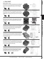
CMB Series
OPERATION
The CMB Series relay is used to detect the presence of AC current.
When the monitored current exceeds the trip point for longer than 30
milliseconds, the internal relay energizes. When the monitored current
drops below the trip point for longer than 0.5 seconds, the internal relay
de-energizes. The Delay-on-Release is incorporated to prevent nuisance
tripping caused by momentary dips in the load line.
An External CT may be used to extend the range of the Current Monitor.
E55826
AC Go/No-Go Current Monitor/Relay
• Easy Installation
CURRENT MONITORS
• No physical connection to the AC line that is being monitored
• Heavy Duty Contacts
• 8-Pin, Plug-in
SPECIFICATIONS
CONTROL VOLTAGE 24 or 120 VAC; 50/60 Hz, 24 VDC
TRIP POINTS
1-10 Amps, Fixed
AC INPUT CURRENT Up to 50 Amps
OUTPUT
170
DIMENSIONS (INCHES)
• Magnetically coupled by passing supply line through
protruding Current Transformer
WIRING
SPDT, 10 Amps @ 240 VAC Resistive;
211 VA @ 120 VAC Inductive:
1/6 Horsepower @ 120 VAC or
1/3 Horsepower @ 240 VAC
POWER CONSUMPTION
3 Watts (Approximately)
RESPONSE TIME
Operate
Release
LIFE EXPECTANCY
Mechanical 10 Million Operations (Minimum)
Electrical 100,000 Operations @
Rated Load
DUTY CYCLE
Continuous
TEMPERATURE
RATING Operate
Storage
SOCKETS
RB-08 or PF083A
ENCLOSURE
Lexan Dust Cover; 8-Pin plug-in
WEIGHT 6 oz
30 mSEC
0.5 SEC
32° to 131°F (0° to +55°C)
-49° to 185°F (-45° to +85°C)
Diversified Electronics
MODEL NUMBER
MODEL NUMBER
CMB
control voltage
24 Volts AC
24 Volts DC (Not ) 120 Volts AC
CURRENT TRIP POINTS
1 amp
2 amps
3 amps
4 amps
5 amps
6 amps
7 amps
8 amps
9 amps
10 amps
800.727.5646
24
24
120
A
D
A
atcdiversified.com
F
A
1
2
3
4
5
6
7
8
9
10
CMC Series
The CMC Series is used to detect a motor jam up and give the equipment an
opportunity to clear itself before going into a lockout and alarm mode.
OPERATION
Control voltage is continuously applied to the CMC monitor. Upon application of the control voltage the Forward and Alarm Relays energize.
When AC current is initially applied, the Inrush Time Delay is initiated
to disable the over current sensor during the inrush period. (See 1 on
graph).
On over current the Forward Relay de-energizes and the unit has a 5
second dead band, then the Reverse Relay energizes for the selected
time delay. Then, the Reverse Relay de-energizes, rests for the Dead
Band and the Forward Relay energizes completing one full cycle (See 2
on graph). After one cycle is complete the Forward relay remains energized if conditions have returned to normal. If an overcurrent remains,
the unit will go through the same operating sequence as before until jam is corrected or the number of preselected cycles have occurred.
INCLUDES REVERSING
RELAY & FAULT
CONDITION COUNTER
AC Over Current Monitor
CURRENT MONITORS
The number of cycles that occur before lockout is field selectable from 1 to 9 cycles. to prevent the faults from accumulating and causing nuisance alarms, a Time Band is initiated upon sensing the first fault. Then, successive occurrences equaling the number of faults within the Time Band will cause alarm. The Formula for the time Band is 70 seconds x (Count-1)
When the number of cycles reaches the pre-selected count, the Forward, Reverse and Alarm Relays lock into the de-energized state. (See 3 on graph) Reset is accomplished by pressing the reset button.
The LED indicator glows when the Forward Relay is energized. The CMC series operates in the fail safe mode as the relays are energized in normal conditions.
An External CT may be used to extend the range of the Current Monitor.
WIRING
SPECIFICATIONS
CONTROL
VOLTAGE
24 or 120 VAC, 50/60 Hz
OVER CURRENT
Inrush Delay
Alternating Delay
Reverse
Operating Time
Number of Fault
Occurrences
OUTPUT (3) Separate SPDT 10 Amp Relay Contacts, (1) Forward,
(1) Reverse, (1) Alarm
INDICATOR
LED glows when Forward Relay is energized
TEMPERATUREOperate
RATING Storage
MODEL
NUMBER
CONTROL
RANGE
OVER
CURRENT RANGE
CMC-24-ASE-5
CMC-24-ASE-10
CMC-120-ASE-5
CMC-120-ASE-10
24 VAC
24VAC
120 VAC
120 VAC
1.0 to 5.0 amps
2.0 to 10 amps
1.0 to 5.0 amps
2.0 to 10 amps
Diversified Electronics
0.1 to 10 SEC, Adjustable
(Forward and Reverse Operations)
5 SEC, Fixed
0.3 to 30 SEC, Adjustable
Selector Switch, 1 to 9 occurrences;
Must occur within the Sampling Time.
32° to 131°F (0° to +55°C)
-49° to 185°F (-45° to +85°C)
ENCLOSURE
Style E: Surface Mount Lexan #8-32 Screw Terminals
WEIGHT 20 oz.
800.727.5646
atcdiversified.com
171
CMD Series
OPERATION
The CMD Series may be used as an Over Current Monitor or an
Under Current Monitor.
The CMD has adjustable Delay-on-Operate and adjustable Delay-onRelease time delays. When the current exceeds the preset current trip
point for longer than the Delay-on-Operate time delay, the internal
relay will energize (Pick-up). When the current drops below the preset
current trip point for longer than the Delay-on-Release time delay, the
internal relay will de-energize (Drop-out). When used as an over current monitor the Delay-on-Operate time delay is used to override inrush
periods. When used as an under current monitor, the Delay-on-Release
timer is used to override a temporary under current condition.
An External CT may be used to extend the range of the Current Monitor.
Universal AC Current Monitor
SPECIFICATIONS
CURRENT MONITORS
CONTROL VOLTAGE 24 or 120 VAC; 50/60 Hz, 24 VDC
OUTPUT DPDT, 10 Amp @ 120 VAC Resistive
RESPONSE TIME
Operate
Release
INDICATORS
Glows when relay is energized
RESET Automatic
HYSTERESIS
5%
TEMPERATURE
RATING Operate
Storage
SOCKETS
RB-08 or PF083A
ENCLOSURE
Lexan Dust Cover; 8-Pin plug-in
WEIGHT 13 oz
0.1 to 10 SEC Adjustable
0.3 to 30 SEC Adjustable
32° to 131°F (0° to +55°C)
-49° to 185°F (-45° to +85°C)
DIMENSIONS (INCHES)
MODEL NUMBER
MODEL NUMBER
CMD
control voltage
24 Volts
120 Volts
24
120
TYPE OF control voltage
AC
DC
E
WIRING
A
D
CURRENT TRIP POINTS
0.05 to 0.25 amp adj. max continuous 3.4 amps
0.2 to 1 amp adj. max continuous 11.9 amps
1.0 to 5.0 amps adj. max continuous 13.4 amps
2.0 to 10 amps adj. max continuous 25 amps
4.0 to 20 amps adj. max continuous 25 amps
172
S
Diversified Electronics
.25
1
5
10
20
800.727.5646
atcdiversified.com
CMG Series
OPERATION
The CMG Series is a self powered Current Monitor/Relay that is used to
detect the presence of AC current. When the monitored current exceeds
the trip point for longer than 400 mSec., the internal relay energizes
(Pick-up). When the monitored current drops below the trip point for
longer than 50 mSec., the internal relay de-energizes (Drop-out). No
physical connection is required as the line to be monitored is magnetically coupled by passing the conductor through the protruding Current
Transformer of the monitor. No external supply is needed to power the
monitor.
The current trip point specified is with one turn through the transformer.
Each time the number of turns through the transformer doubles, the trip
point effectively halves. Example: CMG-0100-20 will trip at 20 amps with
one turn passing through the transformer. By placing two turns through
the transformer, the relay will trip at 10 amps. Likewise, four turns will
cause the relay to trip at 5 amps. (See below)
E55826
AC Self Powered Go/No-Go
Current Monitor/Relays
• No physical connection to the AC line that is being monitored
• Withstands 400 Ampere-Turns Continuous
• No supply voltage required
• Will operate on 24, 120, 240 or 480 VAC lines
• 1/4" Quick Disconnect Terminals
SPECIFICATIONS
CONTROL VOLTAGE Not Required
DIMENSIONS (INCHES)
WIRING
TRIP POINTS
Pick-up
Drop-out
See Order Information
25% below Pick-up
OUTPUT SPST - N.O., 5 Amps @ 240 VAC, Res.
(Available as a normally closed contact upon
request #CMG-0200)
HYSTERESIS
25%
RESPONSE TIME
Operate
Release
ACCURACY
±5% on Pick-up
TERMINATIONS
(2) 1/4" Quick Disconnect Terminals
RESET Automatic
TEMPERATURE
RATING Operate
Storage
ENCLOSURE
Style “D” Surface Mounted
WEIGHT 4 oz.
CURRENT MONITORS
• Magnetically coupled by passing supply line through protruding Current Transformer
400mSec. (Approximately)
50mSec.
32° to 131°F (0° to +55°C)
-49° to 185°F (-45° to +85°C)
MODEL NUMBER
MODEL NUMBER
CURRENT TRIP POINTS
20 amps
24 amps
28 amps
32 amps
36 amps
Diversified Electronics
800.727.5646
CMG
0100
atcdiversified.com
20
24
28
32
36
173
CMG-0101 Series
OPERATION
The CMG-0101 Series is a solid state self powered Current Monitor
that is used to detect the presence of AC current. When the monitored
current exceeds the trip point for longer than 400 mSec., the output
energizes (Pick-up). When the monitored current drops below the
trip point for longer than 400 mSec., the output de-energizes (Dropout). No physical connection is required as the line to be monitored is
magnetically coupled by passing the conductor through the protruding
Current Transformer of the monitor. No external supply is needed to
power the monitor.
SOLID-STATE OUTPUT
SELF POWERED
E55826
AC Go/No-Go Current Monitor
• No physical connection to the AC line that is being monitored
CURRENT MONITORS
• Magnetically coupled by passing supply line through protruding
Current Transformer
• No supply voltage required
• Will operate on 24, 120, 240 or 480 VAC lines
DIMENSIONS (INCHES)
• Easy installation
• 1/4" Quick Disconnect Terminals
SPECIFICATIONS
CONTROL VOLTAGE Not Required
TRIP POINTS
Pick-up
Drop-out
2 Amps
25% below Pick-up
OUTPUT Solid State, SPST-N.O. 1 Amp Resistive;
40 VA Run @ 120 VAC Inductive
MAXIMUM
CONTINUOUS
CURRENT
200 Amp turns @ 25°C
RESPONSE TIME
Operate
Release
2-10 mSEC @ 130 Amps; 400 mSEC
@ 10% over
400 mSEC (Approximately).
ABSOLUTE
280 VAC
MAXIMUM OUTPUT
VOLTAGE
174
ACCURACY
20% on Pick-up
(2) 1/4" Quick Disconnect Terminals
MODEL
NUMBER
DESCRIPTION
TERMINATIONS
RESET
Automatic
CMG-0101
AC GO/NO-GO Current Mon
TEMPERATURE
RATING Operate
Storage
ENCLOSURE
Style “D” Surface Mounted
WEIGHT 4 oz.
32° to 131°F (0° to +55°C)
-49° to 185°F (-45° to +85°C)
Diversified Electronics
800.727.5646
atcdiversified.com
CMI Series
OPERATION
The CMI Series AC Over Current Monitor Relay operates in the failsafe model as the relay is energized (pick-up) when the monitored
AC current is normal. The relay de-energizes (Drop-out) when the
monitored current rises above the preset trip point or the control voltage is removed. When current is initially applied, a time delay begins.
This inhibits the over current sensors while high inrush currents are
present. The delay is field adjustable and is set so the delay period
is slightly longer than the inrush time of the motor. If the monitored
current is above the preset trip point when the delay elapses, the relay
de-energizes. (Figure 1) If the current drops to the normal run current
of the motor prior to the completion of the delay period, the relay
remains energized until the current rises above the trip point, which
indicates an abnormal condition. At that time the relay deenergizes and
remains locked-out until the reset button is pressed or the control voltage is interrupted, and re-applied. (Figure 2) A typical application is for
conveyor jam up detection.
An External CT may be used to extend the range of the Current Monitor.
FAIL SAFE DETECTION
OF MOTOR JAM UPS
AC Over Current Monitor
SPECIFICATIONS
FIGURE 1
FIGURE 2
DIMENSIONS (INCHES)
TRIP POINTS
Pick-up
Drop-out
See Order Information
Press Reset Button or
Restore Control Voltage
OUTPUT DPDT, 10 Amps @ 120 VAC, Resistive
TIME DELAY
0.2 to 10 SEC, Adjustable On Motor Starting
OPERATING TIME
50 mSEC (After Initial Delay has Timed Out)
CURRENT
WITHSTAND
20 Times Nominal for 1 Second
ISOLATION
2500 Volts Between Input and All Other Terminals
INDICATOR
Glows on Normal Current
RESET Manual, Press Button or Interrupt Control Voltage
RESET TIME
100 mSEC After Lock-Out
TEMPERATURE
RATING Operate
Storage
ENCLOSURE
Lexan Surface Mounted; #8-32 Screw Terminals
WEIGHT 11 oz.
CURRENT MONITORS
CONTROL VOLTAGE 24 or 120 VAC/VDC, 50/60 Hz
32° to 131°F (0° to +55°C)
-49° to 185°F (-45° to +85°C)
MODEL NUMBER
MODEL NUMBER
WIRING
Diversified Electronics
CMI
CONTROL VOLTAGE
24 Volts
120 Volts
24
120
CURRENT TRIP POINTS
0.05 to 0.25 amp adj.
0.2 to 1 amp adj.
1.0 to 5.0 amps adj.
2.0 to 10 amps adj.
4.0 to 20 amps adj.
800.727.5646
atcdiversified.com
A
S
E
.25
1
5
10
20
175
CML Series
OPERATION
The CML Series is used to detect over current conditions. The internal relay energizes (Pick-up) when the monitored current exceeds the
preset trip point for longer than the adjustable time delay period. The
adjustable delay is incorporated to prevent nuisance tripping caused by
motor inrush currents. The CML has the manual reset feature. The internal relay de-energizes (Drop-out) when the reset button is pressed.
If the current is below the trip point when the button is released, the
relay will remain de-energized. If the current is above the trip point, the
relay will re-energize.
An External CT may be used to extend the range of the Current Monitor.
INCLUDES MANUAL RESET
AC Over Current Monitor
SPECIFICATIONS
CURRENT MONITORS
CONTROL VOLTAGE 24 or 120 VAC/DC; 50/60 Hz
TRIP POINTS
Pick-up
Drop-out
See order information
5% below Pick-up
(After Manual Reset)
OUTPUT DPDT, 10 Amp @ 120 VAC Resistive
HYSTERESIS
5%
RESPONSE TIME
Operate
INDICATORS
LED Glows On Over Current
(Style “E” Enclosure Only)
RESET Manual
TEMPERATURE
RATING Operate
Storage
32° to 131°F (0° to +55°C)
-49° to 185°F (-45° to +85°C)
ENCLOSURE
Style A
Style E
Lexan Dust Cover; 11-pin Plug-in
Lexan Surface Mounted:
#8-32 Screw Terminals
SOCKET Style A: RB-11 Style E: 13 oz.
WEIGHT 6 oz.
DIMENSIONS (INCHES)
0.1 to 5 SEC, Adjustable
MODEL NUMBER
MODEL NUMBER
176
CML
A
S
CONTROL VOLTAGE
24 Volts
120 Volts
24
120
TYPE OF CONTROL VOLTAGE
AC/DC
A
ENCLOSURE STYLE
Plug-In
Surface Mount
A
E
CURRENT TRIP POINTS
0.05 to 0.25 amp adj.
0.2 to 1 amp adj.
1.0 to 5.0 amps adj.
2.0 to 10 amps adj.
4.0 to 20 amps adj.
WIRING
Diversified Electronics
.25
1
5
10
20
800.727.5646
atcdiversified.com
CMO Series
OPERATION
The CMO Series is used to detect over current conditions. The
internal relay energizes (Pick-up) when the monitored current exceeds
the preset trip point for longer than the adjustable time delay. The delay
is incorporated to prevent nuisance tripping caused by motor inrush
currents. The CMO has an automatic reset feature. The internal relay deenergizes (Dropout) when the current drops 5% below the preset trip
for longer than 0.2 seconds.
An External CT may be used to extend the range of the Current.
AC Over Current Monitor/Relays
SPECIFICATIONS
CONTROL VOLTAGE 24 or 120 VAC/DC; 50/60 Hz
Pick-up
Drop-out
See order information
5% below Pick-up
OUTPUT DPDT, 10 Amps @ 120 VAC, Resistive
HYSTERESIS
5%
RESPONSE TIME
Operate
Release
INDICATOR
LED Glows On Over Current
(Style “E” Enclosure Only)
SOCKET RB-11 Socket for Style A.
RESET Automatic
TEMPERATURE
RATING Operate
Storage
32° to 131°F (0° to +55°C)
-49° to 185°F (-45° to +85°C)
ENCLOSURE
Style A
Style E
Lexan Dust Cover; 11-pin Plug-in
Lexan Surface Mounted:
#8-32 Screw Terminals
WEIGHT Style A: 5 oz. Style E: 13 oz.
CURRENT MONITORS
DIMENSIONS (INCHES)
TRIP POINTS
0.1 to 5 SEC, Adjustable
0.2 SEC
MODEL NUMBER
MODEL NUMBER
WIRING
Diversified Electronics
CMO
CONTROL VOLTAGE
24 Volts
120 Volts
24
120
TYPE OF CONTROL VOLTAGE
AC/DC
A
ENCLOSURE STYLE
Plug-In
Surface Mount
CURRENT TRIP POINTS
0.05 to 0.25 amp adj.
0.2 to 1 amp adj.
1.0 to 5.0 amps adj.
2.0 to 10 amps adj.
4.0 to 20 amps adj.
800.727.5646
atcdiversified.com
A
S
A
E
.25
1
5
10
20
177
CMU Series
OPERATION
The CMU Series is used to detect under current conditions. The
internal relay is energized (Pick-up) when the monitored current is
above the preset trip point. The relay de-energizes (Drop-out) when
the current falls below the trip point for longer than the adjustable
delay. The delay is incorporated to prevent nuisance tripping caused by
momentary line dips. The relay re-energizes when the current rises 5%
above the Drop-out trip point for longer than 0.1 seconds. The relay has
the automatic reset feature.
An external CT may be used to extend the range of the Current Monitor.
AC Under Current Monitor
SPECIFICATIONS
CURRENT MONITORS
CONTROL VOLTAGE 24 or 120 VAC/DC; 50/60 Hz
TRIP POINTS
Pick-up
Drop-out
5% above Drop-out
See order information
OUTPUT DPDT, 10 Amp @ 120 VAC Resistive
HYSTERESIS
5%
RESPONSE TIME
Operate
Release
INDICATORS
Glows When Current is Above Preset Current Trip
Point (Style E Enclosure Only)
RESET Automatic
TEMPERATURE
RATING Operate
Storage
32° to 131°F (0° to +55°C)
-49° to 185°F (-45° to +85°C)
ENCLOSURE
Style A
Style E
Lexan Dust Cover; 11-pin Plug-in
Lexan Surface Mounted:
#8-32 Screw Terminals
SOCKET RB-11 Socket for Style A.
WEIGHT Style A 5 oz. Style E 10.5 oz.
DIMENSIONS (INCHES)
0.1 SEC
0.1 to 5 SEC, Adjustable
MODEL NUMBER
MODEL NUMBER
178
CMU
S
CONTROL VOLTAGE
24 Volts
120 Volts
24
120
TYPE OF CONTROL VOLTAGE
AC
DC
A
D
ENCLOSURE STYLE
Plug-In
Surface Mount
A
E
CURRENT TRIP POINTS
0.05 to 0.25 amp adj.
0.2 to 1 amp adj.
1.0 to 5.0 amps adj.
2.0 to 10 amps adj.
4.0 to 20 amps adj.
WIRING
Diversified Electronics
.25
1
5
10
20
800.727.5646
atcdiversified.com
CT Series
OPERATION
The CT Current Transformers are of the inserted primary type with
the secondary toroidally wound over a core of oriented electrical steel.
The windings are carefully insulated. The entire transformer is then
dipped in PVC insulation compound which insures maximum protection against moisture, acids, alkaline, oils and abrasive particles.
The securely fastened 24” 14 AWG leads are identified to the extent
that the secondary current leaving the CT through the white lead is
in phase with the primary current when the primary conductor enters
the CT from the side identified by the black dot. To prevent shock and
transformer damage, it is important that the secondary leads always
form a continuous circuit when the current is flowing in the primary.
An External CT may be used to extend the range of the AC Current
Monitors.
Current Transformers
DIMENSIONS (INCHES)
• 600 Volt Insulation
• 25 - 400 Hz Operation
• 25/5 to 2500/5 Amperes
SPECIFICATIONS
MODEL
RATIO
CT-25/5
CT-50/5
CT-100/5
CT-200/5
CT-500/5
CT-1000/5
CT-2500/5
25/5
50/5
100/5
200/5
500/5
1000/5
2500/5
CAPACITY ACCURACY GROUP
2 V.A.
2 V.A.
2 V.A.
2 V.A.
2 V.A. 2 V.A.
5 V.A.
6.00%
6.00%
3.00%
1.50%
.60%
.30%
.10%
1
2
3
3
3
4
5
WEIGHT
3 lb. 5 oz.
1lb. 6 oz.
1lb. 4.5 oz.
15 oz.
1 lb. 1 oz.
3 lb.
3 lb. 4 oz.
CURRENT MONITORS
• Optional Mounting Bracket (Add Suffix-B to part number)
NOTES:
GROUP
SIZE
1
2
3
4
5
A
B
C
I
1-1/4
1-1/4
1-1/4
1-7/8
3-3/8
3-3/4
3-7/8
3-1/2
4
6-1/2
2-3/4
1-1/4
1-1/4
1-1/4
1-11/16
5-1/4
4-1/2
4-1/2
4-1/2
7-7/8
II
III
IV
4 2-1/8 0.281 x 0.5
3-7/8 7/8 0.250 x 0.375
3-7/8 7/8 0.250 x 0.375
3-7/8 7/8 0.250 x 0.375
6-1/2 1-1/8 0.281 x .5
1. The current ratio in the table is the ratio of current in the primary/
secondary with one turn on the primary. The ratio can be increased by
adding turns on the primary.
2. The transformers may be installed at some distance from the load.
However, the interconnecting conductor resistance must not cause the
VA rating of the transformer to be exceeded.
3. CTs should not be operated at twice the rated currents. For example,
CT-25/5 should not operate above 50/10 amps. With current too high
overheating will occur.
WIRING
Diversified Electronics
800.727.5646
atcdiversified.com
179
THREE PHASE CURRENT UNBALANCE
Balanced or matched currents on a three phase system are difficult
to maintain because of the many varying factors involved such as,
unequal single phase loading, poor connections and cabling and/or
dirty or burnt starter contacts.
Although these varying factors can be controlled to maintain as close
as possible a balanced line, the unseen conditions such as overheated
motor windings, burnt bearings, low voltage, high voltage and single
phasing need to be constantly monitored to protect your valuable
equipment.
The CLB Series Three Phase Current Unbalance and Over Current
Monitor (page 167) offers this protection.
To determine the condition of your three phase line and to properly
select the CLB Series percent unbalance setting a simple calculation
formula is needed as follows:
CURRENT MONITORS
(I max - I avg)
x 100
I max
Example:
1.
Measure the current on each leg.
Assume
A = 10 amps
B = 12 amps
C = 9 amps
2.
Find Average 10 + 12 + 9 = 31
31
3
I max = 12
I avg = 10.33
3.
Apply formula 12 - 10.33 = 1.67
1.67
12
= 10.33
= .139 x 100 = 13.9% unbalance
EXTERNAL CURRENT TRANSFORMERS
The load or burden that can be connected to the secondary of the
Current Transformer is usually specified in VA. The rated accuracy of
the Current Transformer is guaranteed only when the sum of the VA
ratings of all devices (ampmeters, wattmeters, current monitors, etc.)
connected to the secondary windings does not exceed the specified
VA rating.
If the only load on the Current Transformer is a DE Current Monitor,
its VA rating (approx. 0.15 VA) is small compared to the Current
Transformer rating and can be neglected. This means that the resistance of the wiring can be 80 milliohms max. for the 2 VA units and
200 milliohms max for the 5 V A unit.
Gauge
Ohms per 1000'
Milliohms per foot
The interconnecting conductor resistance must also be considered,
especially when the Transformer is installed at some distance from the
Current Monitor or other load.
AWG 14
2.5
2.5
AWG 16
4.0
4.0
For the wiring, the VA can be calculated using Ohm’s Law:
AWG 18
6.4
6.4
AWG 20
10.0
10.0
VA = E x I = (I x R) x I = I2R
Where I = 5 Amps and R is the DC resistance of the wire.
Example:
All of the standard DE Current Transformers have a rating of 2 VA
except the 2500/5 version which has a 5 VA rating.
For a 2 VA Current Transformer, the length of AWG 16 wire would be:
From the above formula we can also calculate the maximum resistance
that can be connected to the secondary of a Current Transformer:
VA=I R, Hence R = VA
I2
2
Example:
VA = 2 Rmax = VA = 2 = 0.08 Ohms = 80 milliohms
I2 (5)2
VA = 5 Rmax = VA = 5 = 0.2 Ohms = 200 milliohms
80 milliohms
= 20'
4.0 milliohms/ft Because we are dealing with a pair of wires, the maximum distance
from the Current Transformer to the Current Monitor can be only 10
ft.
As we can see, it is important to keep the wire length to minimum,
use heavy wire, and keep all connections clean and tight.
I2 (5)2
180
Diversified Electronics
800.727.5646
atcdiversified.com
ALTERNATING CONTROLLERS
ATC-Diversified Electronics offers a wide variety of models for various
staging requirements. The different models available are: Duplexors,
Triplexors, Quadraplexors, Special Function, and Expandable
Alternating Relays.
The Alternating Relay is used in multiple load installations to assure
equal run time on all loads. They also allow for the addition of more
capacity in the event of excess load requirements. The Alternating
Relay provides equal run time on two or more loads by alternating
the sequence in which the loads are allowed to start up. In each case,
the alternating action is initiated each time the control switch across
designated terminal opens. The control switch may be a float, a
thermostat, a pressure switch, or a timer contact.
The ARM Series, Alternating Controllers, are used in multiple load
installations to assure equal run time on all loads. They also allow
for the addition of more capacity in the event of excess load requirements. The Alternating Controllers provide equal run time on two or
more loads by alternating the sequence in which the loads are allowed
to start up.
All ARM models feature intrinsically safe inputs and logic that allows the outputs to operate even if one of the inputs fails to open or
close. For example: if the off switch fails to close, the lead load will
not energize until both the lead and the lag switches close. An inrush
delay on all models reduces line sags by preventing multiple loads
from energizing simultaneously.
ARA, ARM Series
ALTERNATING RELAYS
ARM-XXX-ABEP
ARA-XXX-AGE
ARM-XXX-ACE
ARA-120-AHE
ARM-XXX-ACEP
ARA-120-AJE
ARM-XXX-ADE
ARA-120-AME
ARM-XXX-ADEP
ARA-120-ANE
ARM-XXX-AFE
ARB-XXX-ABA
ARM-XXX-AFEP
ARB-XXX-ACA
ARM-XXX-AGE
ARB-XXX-ADA
ARM-XXX-AGEP
ARB-XXX-AEA
ARM-XXX-AHE
PUMP & LEVEL CONTROLS
ARA-XXX-AFE
UL LISTED 913
ARM-XXX-ABE
LEAD SELECT
ARA-XXX-AEA
OMIT
ARM-XXX-AAEP
OUTPUT LOGIC (FOSO)
ARA-XXX-ADA
4
OUTPUT LOGIC (SOSO)
ARM-XXX-AAE
3
SELECTABLE SEQUENCING
ARA-XXX-ACA
2
AUTOMATIC ALTERNATING
Model Number
PANEL MOUNT
ARA-XXX-ABA
STYLE SURFACE MOUNT
CSA CERTIFIED
NUMBER OF LOADS
SEQUENCED
FEATURE MATRIX
UL LISTED
E
UL/CANADIAN UL RECOGNIZED
A
FIELD SELECTABLE SEQUENCING
4
AUTOMATIC ALTERNATING
3
EXTERNAL CLOCKING
2
EXPANDABLE
Model Number
ENCLOSURE STYLE
NUMBER OF LOADS
SEQUENCED
FEATURE MATRIX
ARM-XXX-AHEP
Diversified Electronics
800.727.5646
atcdiversified.com
181
ARA, ARB Series
The Duplexor is used in control panels where two loads are required to alternate to provide equal run time on the loads. The alternating action is initiated
by a control switch, which is common with one side of the control voltage. The
output contacts will change states each time the control switch is opened, thus alternating the two loads. The LED indicators show the position of the output relay.
The ARA Series is the standard Duplexor providing automatic alternating sequence. The ARB has the automatic sequencing feature plus the option of locking
it into one sequence. A three position switch permits the field selection of normal
duplexing action, locking in the A-B sequence, or B-A sequence.
SPECIFICATIONS
E55826
CONTROL VOLTAGE 24, 120 VAC/DC, 208, 240, 480 VAC, 50/60Hz,
48 VDC, ±10%
CONTROL switch 1 mA
CURRENT
Duplexor
POWER REQUIRED 3 VA (Approximately)
ALTERNATING RELAYS & CONTROLLERS
DIMENSIONS (INCHES)
DUTY CYCLE
Continuous
LIFE EXPECTANCY
Mechanical 10,000,000 Operations (Minimum)
Electrical 100,000 Operations @ Rated Load
INDICATORS
LED Shows Output Position
TEMPERATURES
RATING Operate
Storage
CONTACT RATING
10 Amps @ 240 VAC, Resistive 1/8 hp @ 120 VAC
1/4 hp @ 240 VAC Inductive 360 VA @ 240 VAC,
Inductive
ENCLOSURE
“A” Lexan® Dust Cover
TERMINATIONS
Industrial Plug-in
WEIGHT 4.5 oz.
-4° to 131°F (-20° to +55°C)
-40° to 185°F (-40° to +85°C)
NOTE: For Analog signal inputs, ATC offers a duplexing pump control —
the ATC-Digitec 3800 Panel Meter, 480 VAC is not available in the D-DPDT
11-Pin configuration
MODEL NUMBER
WIRING
MODEL NUMBER
AR
Type of Alternating Relay
Standard Duplexor
Special Function Duplexor A
B
CONTROL VOLTAGE
24 VAC/DC
48 VDC
120 VAC/DC
208 VAC
240 VAC
380-408 VAC (Consult Factory)
24
48
120
208
240
480
Type of Voltage
VAC or VAC/DC
48 VDC only
A
D
Contact Configuration
SPDT
DPDT (Cross Wired)
DPDT
DPDT (Cross Wired)
B
C
D
E
Enclosure Style
182
Diversified Electronics
800.727.5646
atcdiversified.com
A
A
ARA Series
The Triplexor and Quadraplexor Alternating Relays are designed
for use in multiple load installations that are required to alternate
in sequence while assuring equal run time on all loads. They also allow
for additional loads to run in the event of excess load requirements.
The Triplexor and Quadraplexor have the option of automatic
alterations or external clocking alterations. When the factory installed
jumper is in place the alternating action is initiated by a control switch,
which is common with one side of the control voltage. When the jumper
is removed the alternating action is initiated by an isolated normally
open switch.
ARA-XXX-AFE ALTERNATING ACTION
TRIPLEXOR: For automatic alterations a factory-installed jumper is
in place between terminals 3 and 4. The alternating action is accomplished when the control switch between terminals 2 and 4 opens.
Triplexor
SPECIFICATIONS
ARA-XXX-AGE
CONTROL
VOLTAGE
QUADRAPLEXOR: For automatic alterations, a factory installed jumper
is in place between terminals 11 and 12. The alternating action is accomplished when the control switch between terminals 2 and 3 opens.
CONTROL switch 2 mA
CURRENT
For external clocking alterations, remove the factory-installed jumper
between terminals 11 and 12 and place an isolated normally open
switch between terminals 2 and 12. The alternating action will occur
each time this isolated switch is closed and then re-opened.
POWER REQUIRED
3 VA (Approximately)
DUTY CYCLE
Continuous
In the event of a power failure the Alternating Relays will return to their
quiescent state and continue sequencing loads on one-at-a-time.
DIMENSIONS (INCHES)
24, 120 VAC ±10%, 50/60 Hz
OUTPUT RATING
Triplexor
(3) 5 Amp Resistive, 1/6 hp, 211 VA
@ 120 VAC, Inductive Externally
Switched to terminal #2
Quadraplexor(4) 5 Amp Resistive, 1/6 hp, 211 VA
@ 120 VAC, Inductive Externally
Switched to terminal #2
LIFE EXPECTANCY
Mechanical 10,000,000 Operations (Minimum)
Electrical 100,000 Operations @ Rated Load
INDICATORS
LED’s Show Condition of Outputs
TEMPERATURES
RATING Operate
Storage
ENCLOSURE
Style “E” Lexan® Surface Mounted
TERMINATIONS
(12) #8-32 Screw Terminals
WEIGHT 12 to 14 oz.
-4° to 131°F (-20° to +55°C)
-40° to 185°F (-40° to +85°C)
ALTERNATING RELAYS & CONTROLLERS
For external clocking alterations, remove the factory-installed jumper
between terminals 3 and 4 and place an isolated normally open switch
between terminals 2 and 3. The alternating action will occur each time
this isolated switch is closed and then re-opened.
IND. CONT. EQ.
496Y
NOTE: For Analog signal inputs, ATC offers a duplexing pump control the ATC-Digitec 3800 Panel Meter.
WIRING
MODEL NUMBER
MODEL NUMBER
CONTROL VOLTAGE
24 V Triplexor
120 V Triplexor
120 V Quadraplexor
ARA
24
120
120
Triplexor
Quadraplexor (120 V only) A
F
G
E
The ARA Series Triplexor and Quadraplexor are UL Listed under
UL File Number E55826.
Diversified Electronics
800.727.5646
atcdiversified.com
183
ARA Series
The Expandable Alternating Relays are designed for use in multiple
load installations that are required to alternate in sequence and have
the ability to accept an additional load installation in the future.
ARA-120-AME: The ARA-120-AME is a Duplexor/Triplexor Alternating Relay. With the selector switch in position A, this alternating relay
will duplex the loads on terminals 7 and 9. With the switch in position B,
the Alternating Relay will triplex the three loads on terminals 7, 9 and
11.
For automatic alterations, a factory-installed jumper is in place between
terminals 3 and 4. The alternating action is accomplished when the
control switch between terminals 2 and 4 opens.
Expandable Alternating Relays
ALTERNATING RELAYS & CONTROLLERS
ORDERING INFORMATION
MODEL NUMBER
DESCRIPTION
ARA-120-AME
ARA-120-ANE
Duplexor/Triplexor
Triplexor/Quadraplexor
DIMENSIONS (INCHES)
ARA-120-ANE: The ARA-120-ANE is a Triplexor/Quadraplexor
Alternating Relay. With the selector switch in position A, the Alternating Relay will triplex between the loads on terminals 7, 8 and 9. With the
switch in position B, the Alternating relay will quadraplex the loads on
terminals 7, 8, 9 and 10.
For automatic alterations, a factory installed jumper is in place between
terminals 11 and 12. The alternating action is accomplished when the
control switch between terminals 2 and 3 opens. For external clocking
alterations, remove the factory installed jumper between terminals 11
and 12 and place an isolated normally open switch between terminals 2
and 12. The alternating action will occur each time this isolated switch is
closed and then re-opened.
In the event of a power failure the Alternating Relays will return to their
quiescent state and continue sequencing loads on one-at-a-time.
SPECIFICATIONS
CONTROL VOLTAGE 120 VAC ±10%, 50/60 Hz
CONTROL switch 2 mA
CURRENT
POWER REQUIRED 3 VA (Approximately)
WIRING
184
For external clocking alterations, remove the factory installed jumper
between terminals 3 and 4 and place an isolated normally open switch
between terminals 2 and 3. The alternating action will occur each time
this isolated switch is closed and then re-opened.
Diversified Electronics
DUTY CYCLE
Continuous
OUTPUT RATING
Triplexor
(3) 5 Amp Resistive, 1/6 hp, 211 VA
@ 120 VAC, Inductive Externally
Switched to terminal #2
Quadraplexor(4) 5 Amp Resistive, 1/6 hp, 211 VA
@ 120 VAC, Inductive Externally
Switched to terminal #2
LIFE EXPECTANCY
Mechanical 10,000,000 Operations (Minimum)
Electrical 100,000 Operations @ Rated Load
INDICATORS
LED’s Show Condition of Outputs
TEMPERATURES
RATING Operate
Storage
ENCLOSURE
Style “E” Lexan® Surface Mounted
TERMINATIONS
(12) #8-32 Screw Terminals
WEIGHT 12.5 to 14 oz.
800.727.5646
-4° to 131°F (-20° to +55°C)
-40° to 185°F (-40° to +85°C)
atcdiversified.com
ARA Series
OPERATION
The ARA-120-AHE is a special function Triplexor designed for three
load installations. This model has a field selection switch that is used to
omit one of the three loads for general or emergency maintenance while
duplexing the remaining two loads. The ARA-120-AHE has the option of
alternating on each load cycle or by external clocking. This alternating
relay also allows for additional loads to run in the event of excess load
requirements.
The alternating action is initiated by the control switch between terminals 2 and 4 when the factory installed jumper is in place between
terminals 3 and 4.
INCLUDES
"LOAD OMIT" SWITCH
The alternating action may be initiated externally by removing the factory installed jumper between terminals 3 and 4 and placing an isolated
normally open switch between terminals 2 and 3. An alternating action
will occur each time this isolated switch is closed and then re-opened.
Special Function Alternating Relay
The selection switch has the following positions:
Normal — Normal operation as Triplexor
Omit 1 — Omit load #1 Duplex loads 2 and 3
MODEL NUMBER
DESCRIPTION
Omit 2 — Omit load #2 Duplex loads 1 and 3
ARA-120-AHE
Special Function Alternating Relay
Omit 3 — Omit load #3 Duplex loads 1 and 2
In the event of a power failure, the Alternating Relay will return to its
quiescent state and continue sequencing loads on one-at-a-time.
NOTE: When the “omit load” option is selected, full potential will appear
on the output terminal of the omitted load when the lag switch between
terminals 2 and 5 closes. It is recommended that the H-O-A switch be
placed in the “off” position for the omitted load.
DIMENSIONS (INCHES)
SPECIFICATIONS
CONTROL VOLTAGE 120 VAC ±10%, 50/60 Hz
CONTROL switch 2 mA
CURRENT
POWER REQUIRED 3 VA (Approximately)
DUTY CYCLE
Continuous
OUTPUT RATING
Triplexor
LIFE EXPECTANCY
Mechanical 10,000,000 Operations (Minimum)
Electrical 100,000 Operations @ Rated Load
INDICATORS
LED’s Show Condition of Outputs
TEMPERATURES
RATING Operate
Storage
ENCLOSURE
Style “E” Lexan® Surface Mounted
TERMINATIONS
(12) #8-32 Screw Terminals
WEIGHT 16 oz.
(3) 5 Amp Resistive, 1/6 hp, 211 VA
@ 120 VAC, Inductive Externally
Switched to terminal #2
ALTERNATING RELAYS & CONTROLLERS
ORDERING INFORMATION
WIRING
-4° to 131°F (-20° to +55°C)
-40° to 185°F (-40° to +85°C)
Diversified Electronics
800.727.5646
atcdiversified.com
185
ARA Series
OPERATION
The ARA-120-AJE is a special function Triplexor designed for three
load installations. This model has a field selection switch that is used
to lock the Alternating Relay into a desired sequence. The ARA-120-AJE
has the option of automatically alternating on each load cycle or by
external clocking. This Alternating Relay also allows for additional loads
to run in the event of excess load requirements.
INCLUDES
SEQUENCE LOCKING
SWITCH
Triplexor Alternating Relay
ALTERNATING RELAYS & CONTROLLERS
ORDERING INFORMATION
MODEL NUMBER
DESCRIPTION
ARA-120-AJE
Alternating Relay
DIMENSIONS (INCHES)
A four position rotary switch has been incorporated to permit field
selection of the sequence that is to be maintained. The selection switch
has the following positions:
Normal — Normal operation as a Triplexor
Lock 1 — Locks in sequence 1-2-3; No alternation will occur
while in this position.
Lock 2 — Locks in sequence 2-3-1; No alternation will occur
while in this position.
Lock 3 — Locks in sequence 3-1-2; No alternation will occur
while in this position.
In the event of a power failure, the alternating relay will return to its
quiescent state and continue sequencing loads on one-at-a-time.
SPECIFICATIONS
CONTROL VOLTAGE 120 VAC ±10%, 50/60 Hz
CONTROL switch 2 mA
CURRENT
POWER REQUIRED 3 VA (Approximately)
WIRING
186
The alternating action is initiated by the control switch between terminals 2 and 4 when the factory installed jumper is in place between
terminals 3 and 4. The alternating action may be initiated externally by
removing the factory installed jumper between terminals 3 and 4 and
placing an isolated normally open switch between terminals 2 and 3.
The alternating action will occur each time this isolated switch is closed
and then re-opened.
Diversified Electronics
DUTY CYCLE
Continuous
OUTPUT RATING
Triplexor
LIFE EXPECTANCY
Mechanical 10,000,000 Operations (Minimum)
Electrical 100,000 Operations @ Rated Load
INDICATORS
LED’s Show Condition of Outputs
TEMPERATURES
RATING Operate
Storage
ENCLOSURE
Style “E” Lexan® Surface Mounted
TERMINATIONS
(12) #8-32 Screw Terminals
WEIGHT 17 oz.
800.727.5646
(3) 5 Amp Resistive, 1/6 hp, 211 VA
@ 120 VAC, Inductive Externally
Switched to terminal #2
-4° to 131°F (-20° to +55°C)
-40° to 185°F (-40° to +85°C)
atcdiversified.com
TWO PUMP SEQUENCING: Evenly distributes run time by automatically alternating lead and lag load designations when the off control
switch input opens.
ARM Series
Process
Control
Equipment for
Hazardous
Locations
7M26
UL913
INCLUDES
INTRINSICALLY SAFE INPUTS
UL913 INTRINSICALLY SAFE: Control switch inputs are low voltage/
low current and are electronically isolated from the control voltage
and load alarm contacts.
H-O-A Switches: Hand-Off-Automatic switches allow for manual operation.
LEAD SELECT SWITCH: Disables the automatic sequencing function
and allows loads to be locked into the 2-1 or 1-2 sequence.
CONTROL SWITCH FAULT DETECTION: Unit detects open and shorted
control switch failures.
TEST/CLEAR SWITCH: Verifies function and resets the control switch
fault detection algorithm.
ALARM OUTPUT: Alarm contacts close when a control switch fails or
the system’s capacity is exceeded.
SPECIFICATIONS
CONTROL VOLTAGE 24 or 120 VAC ±10%, 50/60 Hz
CONTROL switch
Open Circuit
Voltage
Short Circuit
Voltage
5 VDC
0.1mA
POWER REQUIRED 4 VA Maximum
INRUSH CURRENT DELAY: Reduces line sags by preventing both
loads from energizing simultaneously.
DUTY CYCLE
Continuous
VERSATILE MOUNTING: Two (2) mounting configurations are available. The standard surface mount has top access to controls and
indicators and is intended for back panel mounting. The panel mount
option is intended for front panel or door cutout access to controls
and indicators.
RESPONSE
Power Up
3 SEC. ±5%
Inrush Current 5 SEC. ±5%
CONTACT
RATING (3) SPST-N.O. 10 Amp Resistive, 1/4 hp, 278 VA
Inductive @ 120 VAC
LED INDICATORS
Designation
Level/Alarm
Lag
Lead
Off
Aux. Off
Load 1
Load 2
Ctrl. Switch
Color
Red
Green
Green
Green
Green
Green
Green
Red
LIFE EXPECTANCY
Mechanical
Electrical
20 Million Operations
75,000 @ Rated Load
TEMPERATURE
RATING Operate
Storage
-4° to 131°F (-20° to +55°C)
-40° to 185°F (-40° to +85°C)
TERMINATIONS
(12) #8-32 Screw Terminals
SPECIAL CONTROLS: ARM-2003 and ARM-2010–Standard
operation without the H-O-A switches ARM-2011–Standard
operation without the Control Switch Failure feature.
ORDERING INFORMATION
Integrated Duplex Controller
MODEL
NUMBER
ARM-XXX-AFE*
ARM-XXX-AFEP*
ARM-2003
ARM-2010
ARM-2011
CONTROL
VOLTAGE
MOUNTING
COMMENTS
24 or 120 VAC
24 or 120 VAC
120 VAC
120 VAC
120 VAC
Surface
Panel
Surface
Panel
Surface
Standard
Standard
Special: w/o
H-O-A switches
Special: w/o
H-O-A switches
Special: w/o
Control switch
failure feature
State
ON
ON
ON
ON
ON
ON
ON
ON
Condition
CS5 Closed
CS4 Closed
CS3 Closed
CS2 Closed
CS1 Aux./cs2
Closed
Load ON
Load ON
Failure
Open/Closed
ALTERNATING RELAYS & CONTROLLERS
The ARM Series Alternating Relay is a microprocessor-based
controller designed for use in dual load installations to assure equal
run time on each load. LED indicators show the status of the unit’s
five intrinsically safe control switch inputs, one alarm, and two load
outputs. H-O-A switches, a lead select switch, and a test/clear button
are provided for manual control. The ARM Series reduces the number
of components required for this application by combining many functions into one unit.
WEIGHT 16 oz.
*Replace XXX with desire control voltage (24, 120)
The ARM Series is UL Listed under UL File Number E151578.
Diversified Electronics
800.727.5646
atcdiversified.com
187
ARM Series
OPERATION
DIMENSIONS (INCHES)
FOUR CONTROL SWITCHING: Do not remove factory-installed jumper
between terminals 2 and 3. The control switches connected to terminals 3 through 6 are labeled OFF (CS2), LEAD (CS3), LAG (CS4)
and ALARM (CS5). Under normal operation the lead load energizes
when the off and lead control switches close in order. The lag load
energizes when the lag closes and the alarm load energizes when
the alarm switch closes. When all four switches reopen in the proper
order all outputs are de-energized and the lead/lag output designations reverse.
ALTERNATING RELAYS & CONTROLLERS
FIVE CONTROL SWITCHING: Remove factory installed jumper
between terminals 2 and 3. After the jumper has been removed, the
additional control switch is connected to terminal 2. The extra switch
functions as an AUXILIARY OFF (CS1) switch. It is used to prevent
loads from running continuously if the primary OFF (CS2) switch
fails to open properly.
FAULT DETECTION ALGORITHM: If any of the control switches open
or close out of order, the alarm output energizes and a fault detection algorithm is used to identify the faulty switch. The faulty switch
is then ignored and the OFF, LEAD, and LAG control switch designations are altered to maintain safe operation.
*Greenlee punch #60071 or equivalent
WIRING
CONTROL DRAWING 190
1. To maintain intrinsic safety, connect the Controller’s Earth
Ground Terminal 8 to the earth ground of the AC Power Supply
feeder. The resistance between the Controller’s Earth Ground
Terminal and Earth Ground shall be less than 1 ohm.
2. Maximum distance between Controller and switch contact is
1000 feet.
188
*Panel Mount Cutout
Diversified Electronics
3. All intrinsically safe wiring shall be separated from non-intrinsically safe wiring. Refer to article 504 of the National Electrical
Code ANSI/NFPA 70 on procedures for intrinsically safe wiring.
4. Switch contact shall be any non-energy storing or generating
mechanical switch type device containing no capacitance or
inductance.
800.727.5646
atcdiversified.com
ARM Series
These Triplex and Quadraplex Controllers are available with
either Sequence-On-Simultaneous-Off (SOSO) or First-On-First-Off
(FOFO) output logic. The special function models are differentiated by a
rotary switch that allows any output to be locked as the lead load or any
Process
one load to be omitted while sequencing only the remaining loads. In adControl
dition to load omission and lead selection, the expandable model can be
Equipment
for
set for 2, 3, or 4 load operation with either SOSO or FOFO logic.
Hazardous
All models feature intrinsically safe inputs and logic that allows
Locations
the outputs to operate properly even if one of the inputs fails to open
7M26
or close. For example: if the off switch fails to close, the lead load will
UL913
not energize until both the lead and the lag switches close. An inrush
delay on all models reduces line sags by preventing multiple loads from
energizing simultaneously.
Alternating Controllers
• 3 and 4 Load Output Models
DIMENSIONS (INCHES)
• 2-4 Load Expandable Model
SPECIFICATIONS
CONTROL VOLTAGE 24 or 120 VAC ±10%, 50/60 Hz
switch VOLTAGE
5.1 Volts open circuit
SWITCH CURRENT
10 μAmps short circuit
POWER REQUIRED 2.5 VA
MODEL NUMBER
MODEL NUMBER
ARM
CONTROL VOLTAGE
24 VAC
120 VAC
24A
120A
NO. OF LOADS
3
3
3
3
4
4
Enclosure Style
OUTPUT SPECIAL
LOGICFUNCTIONS
SOSO none
FOFO none
SOSO Omit/Lead Select
FOFO Omit/Lead Select
SOSO none
FOFO none
mount
No Suffix Surface Mount
P Suffix Panel Mount
E
A
B
C
D
G
H
E
SENSITIVITY
100 k ohm
ISOLATION
2500V Input to Output
DUTY CYCLE
Continuous
RESPONSE
Power Up
Operate
Inrush
Release
CONTACT
RATING All channels, SPST-N.O., 5 Amps per channel
@ 24 or 120 VAC, Resistive; 278 VA, Inductive
LED INDICATORS
ON when corresponding output is ON
LIFE EXPECTANCY
Mechanical
Electrical
20 Million Operations
50,000 Operations
TEMPERATURE
RATING Operate
Storage
-4° to 131°F (-20° to +55°C)
-40° to 185°F (-40° to +85°C)
TERMINATIONS
(12) #8-32 Screw terminals with pressure
clamps
ENCLOSURE
Style “E” Surface mount
WEIGHT
16 oz.
< 1 SEC
< 25 mSEC (switch closure)
5 SEC
< 150 mSEC
ALTERNATING RELAYS & CONTROLLERS
• Intrinsically Safe Inputs
P
The ARM Series is UL Listed under UL File Number E151578.
Diversified Electronics
800.727.5646
atcdiversified.com
189
ARM Series
OPERATION triplex controllers
Intrinsically safe equipment and wiring is equipment and wiring which
is incapable of releasing sufficient electrical or thermal energy under
normal or abnormal conditions to cause ignition of a specific hazardous atmospheric mixture in its most ignitable concentration. Intrinsically
safe terminations and wiring may be brought into any hazardous location of any group classification for which it is accepted without requiring
explosion-proof housing or other means of protection.
ALTERNATING RELAYS & CONTROLLERS
Hazardous locations are classified by the National Electrical Code according to the level of hazard that may exist in the area. A hazardous location
is designated by its class, group and division. The class and group
specify the specific hazardous substances that may exist in the classified
location.
• Class I, Groups A through D – Flammable gasses
• Class II, Groups E through G – Combustible dusts
• Class III, Easily ignitable fibers or flyings
The division indicates the conditions under which the
hazardous substance may be present.
• Division I–Hazardous substances exist continuously or
intermittently under normal operating conditions.
• Division II – Hazardous substances exist within closed containers
or systems from which they can escape only in case of accidental
rupture or breakdown.
WIRING
The ARM-120-AAE and ARM-120-ABE Triplex Controllers
have four switch inputs and three load outputs. The inputs are
designated off, lead, lag and 2nd lag. If the off switch fails to
close, the lead load will not energize until both the lead and
lag switches close. De-energization of the loads depends on
the output logic of the selected controller.
ARM-120-AAE (SOSO): The ARM-120-AAE has sequence-on
simultaneous off output logic. As the 2nd lag, lag and lead
switches open, the loads remain energized. When the off
switch opens, all three loads de-energize simultaneously. If
any switch fails to open, the loads still de-energize when the
off switch opens. The lead advances one position each time
the loads de-energize.
ARM-120-ABE (FOFO): The ARM-120-ABE has first-onfirst-off output logic. When the 2nd lag switch opens, all
three loads remain energized. The lag switch opens next, and
the lead load de-energizes. When the lead switch opens, the
lag load de-energizes. Finally, the off switch opens, and the
second lag load de-energizes. At the end of each cycle the
lead advances one position for each load energized during
the cycle. For example: if loads one and two cycle on and off,
the lead will advance two positions. Load three will be the lead
load for the next cycle.
The ARM-120-ACE (SOSO) and ARM-120-ADE (FOFO)
Special Function Triplex Controllers have the same features and
operations as the ARM-120-AAE and ARM-120-ABE respectively with the addition of an eight-position field selection switch.
The switch allows any one load to be omitted from the sequence or locked in the lead position. An automatic test mode
is also provided for system verification and troubleshooting.
LOAD OMIT MODE: One load may be omitted from the sequence for general or emergency maintenance while alternating the remaining loads.
LEAD SELECT MODE: The controller may be locked into a
desired sequence to equalize motor run time.
AUTOMATIC TEST MODE: The controller energizes the loads
one at a time for five second intervals.
field selection switch
190
POS.
0
1
2
3
4
5
6
7
FUNCTION
NORMAL
1 2 3
2 3 1
3 1 2
OMIT L1
OMIT L2
OMIT L3
TEST
Diversified Electronics
800.727.5646
atcdiversified.com
The ARM-120-AGE and ARM-120-AHE Quadraplex Controllers have
five switch inputs and four load outputs. The inputs are designated off,
lead, lag, 2nd lag, and 3rd lag. With the off switch closed, the loads
energize in sequence upon closure of the lead, lag, 2nd lag, and 3rd
lag inputs. If the off switch fails to close, the lead load will not energize
until both the lead and lag switches close. De-energization of the loads
depends on the output logic of the selected controller.
ALTERNATING RELAYS & CONTROLLERS
ARM-120-AGE (SOSO): The ARM-120-AGE has sequence-on simultaneous off output logic. As the 3rd lag, 2nd lag, lag and lead switches open,
the loads remain energized. When the off switch opens, all four loads
de-energize simultaneously. If any switch fails to open, the loads still deenergize when the off switch opens. The lead advances one position each
time the loads de-energize.
ARM-120-AHE (FOFO): The ARM-120-AHE has first-on-first-off
output logic. When the 3rd lag switch opens, all four loads remain
energized. The 2nd lag switch opens next, and the lead load de-
energizes. When the lag switch opens, the lag load de-energizes.
Next, the lead switch opens, and the 2nd lag load de-energizes.
Finally, the off switch opens, and the 3rd lag load de-energizes. At
the end of each cycle the lead advances one position for each load
energized during the cycle. For example: if loads one and two cycle
on and off, the lead will advance two positions. Load three will be the lead load for the next cycle.
WIRING
Diversified Electronics
ARM Series
OPERATION quadraplex controllers
800.727.5646
atcdiversified.com
191
ARM Series
soso operation
fofo operation
STEP 1
OFF
STEP 1
This example illustrates the normal
operation of the Triplex Controller in a
2ND pump down application with four normally
LAG open dry float switches. The switches are
LAG
designated off, lead, lag, and 2nd lag. The
example begins with all switches open and
LEAD
all loads de-energized.
STEP 2
This example continues from SOSO
operation step four. With all float switches
2ND closed, all loads are energized.
LAG
LAG
LEAD
OFF
STEP 2
ALTERNATING RELAYS & CONTROLLERS
As the fluid level rises, the OFF switch
closes, no loads are energized.
STEP 3
As the fluid level falls, the 2nd lag switch
opens. All loads remain energized. Each
float switch in descending order acts as the
OFF switch for the preceding float.
STEP 3
If the fluid level continues to rise, the lead
switch closes and load 1 energizes.
STEP 4
When the lag switch opens, load 1 de-
energizes. Loads 2 and 3 remain energized.
STEP 4
As the fluid level continues to rise each
successive float switch closure sequentially
energizes a corresponding load.
STEP 5
When the lead switch opens, load 2 deenergizes. Load 3 is held on by the OFF
switch.
STEP 5
When the fluid level falls and each float
switch opens, the loads remain energized
so long as the OFF switch remains closed.
No external auxiliary contacts are required
to accomplish this latch feature.
When the OFF switch opens, load 3 deenergizes and the lead advances three
positions. At the end of each cycle the
lead advances one position for each load
energized during the cycle. This particular
example reverts back to SOSO OPERATION
1-4 wherein load 1 would again be the lead
load.
STEP 6
When the fluid level falls below the OFF
switch, all loads simultaneously de-energize, and the alternating logic advances
one position. The next rise and fall in fluid
level and successive operation of load
switches will result in the SOSO load operation as follows: 2-3-1, 3-1-2, and back to
1-2-3 as in Step 1.
192
Diversified Electronics
800.727.5646
atcdiversified.com
Class and group specify the type of hazardous substance that may
exist in the classified location. The division indicates the conditions
under which the hazardous substance may be present.
CLASS I
Locations in which flammable gases or vapors may be present in the air in quantities sufficient to produce explosive
or ignitable mixtures.
CLASS II
Locations which are hazardous because of
the presence of combustible dust.
GROUP A
Atmospheres containing acetylene.
GROUP E
Atmospheres containing metal dust including aluminum, magnesium and their commercial alloys and other metals of similarly
hazardous characteristics.
GROUP B
Atmospheres containing hydrogen, gases
or vapors of equivalent hazard, such as
manufactured gas.
GROUP F
Atmospheres containing carbon black, coal
or coke dust.
GROUP C
Atmospheres containing ethyl-ether vapors,
ethylene or cyclopropane.
GROUP G
Atmospheres containing flour, starch or
grain dusts.
GROUP D
Atmospheres containing gasoline, hexane, naphtha, benzine, butane, propane,
alcohol, acetone, benzol, lacquer solvent
vapors or natural gas.
CLASS III
Locations which are hazardous because of
the presence of easily ignitable fibers or
flyings, but in which such fibers or flyings
are not likely to be in suspension in air in
quantities sufficient to product ignitable
mixtures.
DIVISION I
Locations in which hazardous concentrations in the air exist continuously, intermittently or periodically under normal
operating conditions.
DIVISION II
Locations in which hazardous concentrations are handled, processed or used
but are normally confined within closed
containers or closed systems from which
they can escape only in case of accidental
rupture or breakdown.
Process Control
Equipment for Hazardous Locations
7M26
UL913
Information
INTRINSICALLY SAFE SINGLE & MULTIPLE CHANNEL INPUTS
Hazardous locations are classified by the National Electrical Code according to the level of hazard that may exist in the area. A hazardous
location is designated by its class, group and division.
ISOLATED SWITCHES
ISOLATED SWITCHES
The ATC Diversified Electronics series of Isolated Switches have been tested and approved for
listing under Underwriters Laboratories (UL) UL913 Intrinsically Safe Apparatus and Associated
Apparatus. The input(s) to these switches have been approved for use in all classes, groups and
divisions of hazardous locations.
Diversified Electronics
800.727.5646
atcdiversified.com
193
ISO Series
OPERATION
The ISO Series single channel devices are used to provide a safe
and reliable means of controlling loads from hazardous locations
without releasing sufficient energy, under normal or abnormal
conditions, to cause ignition of a flammable or combustible
atmospheric mixture while in its most easily ignited concentration.
An isolated output turns on when the control switch input from the
hazardous location is closed. When the control switch input opens,
the isolated output turns off. The Style A single channel plug-in devices come equipped with integral spring mating clips which secure
the device to the base make this unit the only UL913 Intrinsically
Safe plug-in associated apparatus available on the market today.
The Style N, surface mounted enclosure is sealed with a high quality epoxy resin material and has five (5) #8-32 screw terminals.
Process Control Equipment for Hazardous Locations
7M26
UL913
Single Channel Isolated Switch
DIMENSIONS (INCHES)
SPECIFICATIONS
ISOLATED SWITCHES
CONTROL VOLTAGE 24 or 120 VAC ±10%, 50/60 Hz
control switch
Open Circuit Voltage
Open Circuit Voltage
RESPONSE
Operate
Release
16 VDC
200 μAmps
6 mSEC (Approx.)
2.5 mSEC (Approx.)
POWER REQUIRED 1.5 VA
DUTY CYCLE
Continuous
CONTACT
RATING SPST-N.O., 10 amps @ 24
or 120 VAC, Resistive; 278 VA, Inductive
SENSITIVITY
100 k ohm
ISOLATION
2500 Volts, Input to Output
LIFE EXPECTANCY
Mechanical
Electrical
INDICATORS
On When Output is On
TEMPERATURE
RATING Operate
Storage
ENCLOSURE
Style “E” Lexan® Surface Mounted
TERMINATIONS
(12) #8-32 Screw terminals
WEIGHT
20 oz.
20 Million Operations
50,000 Operations @ Rated Load
-4° to 131°F (-20° to +55°C)
-40° to 185°F (-40° to +85°C)
ordering information
MODEL
NUMBER
CONTROL
VOLTAGE
ENCLOSURE
STYLE
ISO-24-AFA
ISO-120-AFA
ISO-24-AFN
ISO-120-AFN
24 VAC
120 VAC
24 VAC
120 VAC
A
A
N
N
Style "A" Socket Included
194
Diversified Electronics
800.727.5646
atcdiversified.com
The ISO/ISL Series multiple channel devices are used to provide a
safe and reliable means of controlling loads from hazardous locations
without releasing sufficient energy under normal or abnormal conditions
to cause ignition of a flammable or combustible atmospheric mixture
while in its most easily ignited concentration. An isolated output turns
on when the corresponding control switch input from the hazardous
location is activated. When using normally closed control switch inputs,
a jumper should be installed between terminals 1 and 2. Normally open
control switch inputs do not require the optional jumper. When the non-latching ISO Series control switch input is activated, its corresponding output turns on. When the control switch input is deactivated,
its output turns off. When the latching ISL Series control switch input
2, 3 or 4 is activated, its corresponding output turns on. When control
switch 2, 3 or 4 is deactivated, its corresponding output remains latched
on as long as control switch input 1 is activated; otherwise it turns off
immediately. Control switch input 1 also controls output 1 just as in the
non-latching ISO Series.
ISO, ISL Series
OPERATION
Process Control Equipment for Hazardous Locations
7M26
UL913
Multiple Channel Isolated Switch
SPECIFICATIONS
DIMENSIONS (INCHES)
control switch
Open Circuit Voltage
Open Circuit Voltage
RESPONSE
TIMES Operate
Release
6.2 VDC
10 μAmps
6 mSEC (Approx.)
2.5 mSEC (Approx.)
POWER REQUIRED 2.5 VA
ordering information
MODEL
NUMBER
CONTROL
VOLTAGE
CHANNELS
ISL-24-AAE
ISL-24-ABE
ISL-24-ACE
ISL-120-AAE
ISL-120-ABE
ISL-120-ACE
ISO-24-AAE
ISO-24-ABE
ISO-24-ACE
ISO-120-AAE
ISO-120-ABE
ISO-120-ACE
24 VAC
24 VAC
24 VAC
120 VAC
120 VAC
120 VAC
24 VAC
24 VAC
24 VAC
120 VAC
120 VAC
120 VAC
2
3
4
2
3
4
2
3
4
2
3
4
Diversified Electronics
DUTY CYCLE
Continuous
CONTACT
RATING SPST-N.O., 5 amps per channel @ 24 or
120 VAC, Resistive; 278 VA, Inductive
ISOLATION
2500 Volts, Input to Output
LIFE EXPECTANCY
Mechanical
Electrical
INDICATORS
On When Corresponding Output is On
TEMPERATURE
RATING Operate
Storage
ENCLOSURE
Style “E” Lexan® Surface Mounted
TERMINATIONS
(12) #8-32 Screw terminals
WEIGHT
8 oz.
800.727.5646
atcdiversified.com
ISOLATED SWITCHES
CONTROL VOLTAGE 24 or 120 VAC ±10%, 50/60 Hz
20 Million Operations
50,000 Operations @ Rated Load
-4° to 131°F (-20° to +55°C)
-40° to 185°F (-40° to +85°C)
195
ISO, ISL Series
ISOLATED SWITCHES
196
Diversified Electronics
800.727.5646
atcdiversified.com
AC Series
The AC 2020 Compressor Protector provides multimode time delays,
reset selections and a memory capability which indicates using LED’s,
the last fault condition. This offers not only protection for the compressor in adverse electrical conditions but also a method to readily
determine the type of fault occurrence.
operating voltage
Auto Ranges
240 VAC
480 VAC
190-270 VAC, Adj., 50/60 Hz
380-540 VAC, Adj., 50/60 Hz
E55826
3-Phase Compressor Protector
SPECIFICATIONS
CONTROL VOLTAGE 24 or 120 VAC ±10%, 50/60 Hz
trip points
Under Voltage -10% of Setting
Over Voltage +10% of Setting
Hysteresis
5% of Nominal Setting
RESPONSE
TIMES Pick-Up
Drop-Out
Auto Mode: 0.05 to 5 Min.
(Adj) Delay-On-Make
Delay Mode: 3 Min. (Fixed)
Delay-On-Break
Over/Under Voltage,
Phase Loss: 2 SEC (Approximately)
• Automatic Voltage Ranging
PROTECTS AGAINST:
• Universal Control Voltage
• Phase Loss
• Condition/Fault Indicators
• Under Voltage
• Automatic/Manual Reset
• Over Voltage
• Last Fault Memory
• Phase Reversal
• Delay-On-Make
• Short Cycling
• Delay-On-Break
• Auxiliary Contacts
• Easy Installation
POWER REQUIRED <5 VA
MAXIMUM
VOLTAGE
HVAC CONTROLS
ordering information
550 VAC
PHASE sequence ABC (Will Not Operate On CBA Sequence)
output RATING 278 VA Inductive; 10 Amps Resistive @ 240 VAC
CONFIGURATION
Control
Auxiliary
MODEL
NUMBER
AC-2020
DESCRIPTION
3-Phase Compressor Protector
SPST-N.O.
SPDT
MODE SELECTIONS Automatic; Manual; Delay-On-Break
RESET SWITCH
With Memory, Without Memory, Auto Reset,
Manual Reset
TRANSIENT
WITHSTAND
1500 V @ 8X 20 Microseconds
TEMPERATURE
RATING Operate
Storage
ENCLOSURE
Style “E” Lexan® Surface Mounted
TERMINATIONS
(12) #8-32 Screw Terminals
WEIGHT 6 oz.
-4° to 131°F (-20° to +55°C)
-40° to 185°F (-40° to +85°C)
Diversified Electronics
800.727.5646
atcdiversified.com
197
AC-503 Series
This family of HVAC controls provides short cycle protection by
locking out the compressor for a period of time after a voltage or
thermostat interruption. Subsequent interruptions will not increase the
delay period. Since the delay begins when the interruption occurs, the
temperature control is not affected. Under normal operating conditions,
the compressor off time is longer than five (5) minutes. In this case, the
use of these timers will not lengthen this off cycle.
This field adjustable model will operate on control voltages of 19 VAC
through 288 VAC. Unlike most universal voltage timers, the AC-503 is
a two (2) terminal device that simply connects in series with the control
voltage, thermostat and control relay making for easy installation. This
timer is engineered to provide true thermostat interruption protection even when there is a continuous current flow through the thermostat’s cooling anticipator.
Delay-On-Break Timers
NOTE: When used on 120/240 VAC control circuits, the external jumper
should be cut. This disables the 24 VAC bypass circuit.
HVAC CONTROLS
SPECIFICATIONS
ordering information
MODEL
NUMBER
AC-503
DESCRIPTION
Delay-On-Break Timer
CONTROL VOLTAGE 24/120 or 208/240 VAC
OUTPUT RATING
250 VA Inrush; 25 VA Run @ 24 VAC, or 1250
VA Inrush; 125 VA Run @ 120/240 VAC
TIME DELAY
0.1 to 5 min. Adjustable
DIMENSIONS
2.0" x 2.0" x .75" high
WEIGHT 2.5 oz.
wiring
198
Diversified Electronics
800.727.5646
atcdiversified.com
AC-505-5
The AC-505-5 provides short cycle protection by locking out the
compressor for a period of time after a voltage or thermostat interruption. Subsequent interruptions will not increase the delay period. Since
the delay begins when the interruption occurs, the temperature control
is not affected. Under normal operating conditions, the compressor off
time is longer than five (5) minutes. In this case, the use of these timers will not lengthen this off cycle.
This is an easy to install, two (2) wire Short Cycle Timer that connects
in series with the control voltage and control relay. The AC-505 is
engineered to provide true thermostat interruption protection even
when there is continuous current flow through the thermostat’s cooling
anticipator.
Delay-On-Break Timer
ordering information
OUTPUT RATING
250 VA Inrush; 25 VA Run @ 24 VAC @ 77°F
5 min. ±20%
MODEL
NUMBER
DESCRIPTION
TIME DELAY
DIMENSIONS
2.65" x 2.13" x .875" high.
AC-505-5
Delay-On-Break Timer
WEIGHT 3 oz.
HVAC CONTROLS
SPECIFICATIONS
CONTROL VOLTAGE 24 VAC
wiring
Diversified Electronics
800.727.5646
atcdiversified.com
199
ASC-500
This family of controls provides short cycle protection by locking out
the compressor for a period of time after a voltage or thermostat interruption. Subsequent interruptions will not increase the delay period.
Since the delay begins when the interruption occurs, the temperature
control is not affected. Under normal operating conditions, the compressor off time is longer than five (5) minutes. In this case, the use of
these timers will not lengthen this off cycle.
These are easy to install two (2) terminal Short Cycle Timers that
connect in series with the control voltage and control relay. The 24 VAC
model employs a built-in bypass circuit for allowing continuous flow
through the thermostat’s cooling anticipator while the timer output is
off.
E55826
HVAC CONTROLS
Delay-On-Break Timer
ordering information
MODEL
NUMBER
DESCRIPTION
5 Min. 24 VAC
5 Min. 120 VAC
5 Min. 240 VAC
3 Min. 120 VAC
3 Min. 240 VAC
ASC-500-5
ASC-501-5
ASC-502-5
ASC-501-3
ASC-502-3
SPECIFICATIONS
CONTROL VOLTAGE
ASC-500-5
ASC-501-5
ASC-501-3
ASC-502-5
ASC-502-3
24 VAC
110/120 VAC
OUTPUT RATING
ASC-500-5
ASC-501-5
ASC-501-3
ASC-502-5
ASC-502-3
250 VA Inrush; 25 VA Run
@ 24 VAC
1250 VA Inrush; 125 VA Run
@ 120 VAC
1250 VA Inrush; 125 VA Run
@ 240 VAC
DIMENSIONS
2.0" x 2.0" x .75" high
WEIGHT 3 oz.
208/240 VAC
wiring
200
Diversified Electronics
800.727.5646
atcdiversified.com
AC-800 Series
The ATC Diversified STAR PERFORMER provides short cycle protection
of compressors by delaying restart after a voltage or control circuit
interruption. When the interruption occurs, the control relay drops out.
The delay period begins when power is restored, providing random
restart.
This universal voltage Delay-on-Make Short Cycle Timer provides the
ultimate protection against short cycling of a compressor. The Star
Performer offers true thermostat interruption protection even in 24 VAC
control circuits.
The general conception of thermostat operation is that when the
mercury tilts open, all control circuit current stops. The fact is that the
cooling anticipator located inside most 24 volt thermostats does allow
a small amount of current to flow (trickle current). This trickle current
fools most Delay-on-Make Short Cycle Timers, as they will not reset as a
result of this continuous current.
E55826
"STAR PERFORMER"
NOTE: When used on 120/240 VAC control circuits, the external jumper
should be cut. This disables the 24 VAC bypass circuit.
SPECIFICATIONS
ordering information
CONTROL VOLTAGE 24/120, 208/240 VAC
OUTPUT RATING
250 VA Inrush; 25 VA Run @ 24 VAC, or 1250
VA Inrush; 125 VA Run @ 120/240 VAC
TIME DELAY
0.2 to 8 min. Adjustable
WEIGHT 2.5 oz. to 3 oz.
MODEL
NUMBER
AC-800
DESCRIPTION
Delay-On-Make Timer
HVAC CONTROLS
Delay-On-Make Timers
The STAR PERFORMER is engineered to provide true thermostat interruption protection even when the trickle current is present. The adjustable delay is ideal for providing random starting in multiple equipment
installations.
wiring
Diversified Electronics
800.727.5646
atcdiversified.com
201
ASC-600 Series
The ASC-600 Series provides short cycle protection of compressors
by delaying restart after a voltage or control circuit interruption. When
the interruption occurs, the control relay drops out. The delay period
begins when power is restored, providing random restart.
These are easy to install, two (2) terminal short cycle timers that
connect in series with the control voltage and control relay. The 24 VAC
models employ a built-in bypass circuit for allowing continuous current
flow through the thermostat’s cooling anticipator while the timer output
is off.
E55826
Delay-On-Make Timer
HVAC CONTROLS
ordering information
MODEL
NUMBER
DESCRIPTION
ASC-600-3
ASC-601-3
24 VAC Delay-On-Make Timer
120/240 VAC
Delay-On-Make Timer
SPECIFICATIONS
CONTROL VOLTAGE ASC-600-3
ASC-601-3
24 VAC
120/240 VAC
OUTPUT
RATING
250 VA Inrush; 25 VA
Run @ 24 VAC
1250 VA Inrush; 125 VA
Run @ 120/240 VAC
ASC-600-3
ASC-601-3
TIME DELAY
3 min. ±20%
WEIGHT 3 oz.
wiring
202
Diversified Electronics
800.727.5646
atcdiversified.com
AC-410 Series
The AC-410 Series are plug in Phase Sequence and Loss Monitors that
protect 3 phase refrigeration equipment from adverse line conditions
such as:
PHASE LOSS (SINGLE PHASING): When any one phase drops to 83% or
less of the adjustment setting.
UNDER VOLTAGE (BROWN OUTS): When all three phase voltages drop
to 90% or less of the adjustment setting.
PHASE REVERSAL (IMPROPER SEQUENCE): When the wrong sequence
is applied to the equipment.
OPERATION
STYLE A
When any of the mentioned occurs, the internal control relay drops out
and a 3 minute delay-on-break time delay begins. This delay is used to
lock out the compressor, allowing time for head pressure to equalize.
When the delay has completed, the relay will re-energize provided all
conditions are corrected and the external control voltage is present on
terminals six (6) and seven (7). A green indicator glows when all line
conditions are normal and a red indicator shows when the timer is in its
delay.
Phase Sequence & Loss Monitor
Consult factory for available models.
SPECIFICATIONS
DROP OUT
1 Ø Low
3 Ø Low
83% of Adjustment Setting
90% of Adjustment Setting
PHASE SEQUENCE
ABC (Will Not Operate CBA)
TIME DELAYS
Operate
Release
3 Minutes ±20%
100 Milliseconds
OUTPUT RATING
AC-410
AC-411 &
AC-412
SPDT, 10 Amps @ 240 VAC,
Resistive; 470 VA, Inductive.
SPDT, 10 Amps @ 240 VAC,
Resistive; 180 VA, Inductive
TEMPERATURE
rating Operate
Storage
-4° to 131°F (-20° to +55°C)
-40° to 185°F (-40° to +85°C)
ENCLOSURE
Style “A”
WEIGHT 7 oz.
Diversified Electronics
wiring
800.727.5646
atcdiversified.com
HVAC CONTROLS
ordering information
203
CV Series
CV-100RS
1.5" X 2.65" X 3.75"H
OPERATION
This switch should be positioned to match the line voltage for proper
operation. When the line voltage goes below (brown out) or above the
preselected operating range, the internal relay drops out removing
the plugged-in appliance from these adverse fault conditions. When
the voltage returns to the normal operating range, a five (5) minute
delay begins. Upon completion, the internal relay picks up allowing the
plugged-in appliance to start. LED indicators give an immediate visual
reference as to the status of the control. The GREEN LED indicates
conditions are normal. When a fault condition occurs the GREEN LED will
extinguish and the RED LED will glow. When a fault condition has been
corrected, the RED LED will begin to flash. The RED LED will continue to
flash until the five (5) minute delay period elapses. At the end of the
delay period the RED LED will extinguish and the GREEN LED will glow.
When both LED’s are extinguished, a total loss of power is indicated.
CV-230-AFN
HVAC CONTROLS
Single Phase Under/Over
Voltage Monitor
204
The CV-100 and 200 Series are Under/Over Voltage Monitors
combined with short cycle protectors used for appliance control.
These units employ a user selectable voltage range Set Point switch.
The CV-XXX-AFN Series monitors under voltage only and do not feature
LED indicators. They also incorporate the five (5) minute short cycle
delay. This style is epoxy encapsulated to protect against adverse
environmental conditions.
MODEL
NUMBER
SET VOLTAGEUNDER VOLTAGEOVER VOLTAGEOUTPUT RATING RECEPTACLE WEIGHT
POINT 50/60 HZ DROP OUT PICK UP PICK UPDROP OUT
RUNLOCK ROTOR STYLE
CV-100RS
110
120
110 VAC
120 VAC
87 VAC 95 VAC 95 VAC
103 VAC
120 VAC 128 VAC
131 VAC 140 VAC
15A
15A
40A
40A
8.5 oz
C V-200RS-15
230
240
230 VAC
240 VAC
190 VAC 202 VAC 198 VAC
210 VAC
243 VAC 253 VAC
258 VAC 268 VAC
15A
15A
52A
52A
8.5 oz.
C V-200RS-20
230
240
230VAC
240 VAC
190 VAC 202 VAC 198 VAC
210 VAC
243 VAC 253 VAC
258 VAC 268 VAC
20A
20A
72A
72A
8.5 oz
CV-120-AFN
CV-230-AFN
CV-240-AFN
N/A
N/A
N/A
120 VAC
230 VAC
240 VAC
95 VAC 190 VAC 202 VAC 103 VAC
198 VAC
210 VAC
20A
20A
20A
52A
52A
52A
Not Applicable
1/4" quick"
disconnect
terminals
8.5 oz.
Diversified Electronics
N/A
N/A
N/A
N/A
N/A
N/A
800.727.5646
atcdiversified.com
SPM Series
OPERATION
The ATC Diversified SPM Series Single Channel Seal Failure module is
a specialized control for monitoring the shaft seal of a submersible
pump motor. A leak is detected by sensing the position of a resistive float switch installed in the seal cavity. When the resistance drops
below the sensitivity rating, the output relay energizes and the LED
illuminates.
E55826
DIMENSIONS (INCHES)
Single Channel Seal Failure Alarm
CONTROL voltage 120 VAC, 50/60 Hz
SWITCH voltage
9 VDC
ISOLATION
2500 Volts
POWER required 2 VA
wiring
RB-11/PF013A
DUTY cycle
Continuous
SENSITIVITY
470 Ω ±10% Fixed
470 Ω to 10K Ω ±10% Adjustable
4.7K Ω to 100K Ω ±10% Adjustable
CONTACT RATING
DPDT, 10 A @ 250 VAC Resistive,
360 VA Inductive
RESPONSE TIMES
Operate
Release
LIFE EXPECTANCY
Mechanical 10,000,000 Operations (Minimum)
Electrical 50,000 Operations @ Rated Load
INDICATORS
Red LED illuminates when leak is detected
TEMPERATURE
RATING Operate
Storage
ENCLOSURE
11-Pin plug-in “A” style enclosure
WEIGHT 8 oz.
SPECIAL CONTROLS
SPECIFICATIONS
15 ms (approximately)
8 ms (approximately)
-4° to 131°F (-20° to +55°C)
-40° to 185°F (-40° to +85°C)
MODEL NUMBER
MODEL NUMBER
SPM
SENSITIVITY
470 Ω ±10% Fixed
470 Ω to 10K Ω ±10% Adjustable
4.7K Ω to 100K Ω ±10% Adjustable
120
AAA
Diversified Electronics
470
10K
100K
800.727.5646
atcdiversified.com
205
SPM Series
OPERATION
The ATC Diversified Electronics SPM Series
Seal Failure module
is a specialized control for monitoring the shaft seals of
submersible pump motors. Leaks are detected by sensing the conductivity of the contaminating fluid through probes installed in the seal
cavity. When a seal begins to leak, the seal failure module energizes
one of its SPST output relays indicating that the seal needs to be
replaced before the motor is damaged. The sensitivity of the probe inputs is field adjustable. When the resistance between one of the probe
inputs and the common connection drops below the sensitivity setting,
the corresponding output relay and LED are activated.
E55826
Dual Channel Seal Failure Alarm
DIMENSIONS (INCHES)
SPECIAL CONTROLS
SPECIFICATIONS
CONTROL voltage 120 VAC, 50/60 Hz
SWITCH voltage
9 VDC
ISOLATION
2500 Volts
POWER required 2 VA
DUTY cycle
Continuous
SENSITIVITY
10K Ω to 25K Ω ±10% Adjustable
4.7K Ω to 100K Ω ±10% Adjustable
CONTACT RATING
(2) SPST-N.O., 5 A @ 120 VAC Resistive,
345 VA Inductive
LIFE EXPECTANCY
Mechanical 20 Million Operations
Electrical 50,000 Operations @ Rated Load
INDICATORS
Red LED illuminates when leak is detected
TEMPERATURE
RATING Operate
Storage
ENCLOSURE
8-Pin plug-in “A” style enclosure
WEIGHT 8 oz.
-4° to 131°F (-20° to +55°C)
-40° to 185°F (-40° to +85°C)
wiring
MODEL NUMBER
MODEL NUMBER
RB-08/PF083A
SPM
SENSITIVITY
10K Ω to 25K Ω ±10% Adjustable
4.7K Ω to 100K Ω ±10% Adjustable
206
120
ABA
Diversified Electronics
25K
100K
800.727.5646
atcdiversified.com
SPM Series
OPERATION
The non-volatile Latching Temperature Switch relay monitors a
normally-closed-low temperature switch. It incorporates a bistable
relay that retains its state during power failures. LEDs indicate the
status of the relay, and connections for an external reset button are
provided for manual control. The reset inputs of multiple units may
be connected to a single push button as long as proper polarity is
observed when making the connections. Under normal conditions the
temperature switch is closed and the relay is de-energized. When the
temperature switch opens, the relay energizes and latches on until the
temperature switch re-closes and the reset button is pressed. The unit
will function properly with zero to 2k Ω of resistance in series with the
temperature switch.
Temperature Switch Relay
DIMENSIONS (INCHES)
CONTROL voltage 120 VAC, 50/60 Hz
POWER REQUIRED 2 VA
wiring
ACA
ADA
RB-11/PF013A
DUTY CYCLE
Continuous
CONTACT
RATING SPM-120-ACA
SPM-120-ADA
RESPONSE TIMES
Operate
Release
LIFE EXPECTANCY
Mechanical 30 Million Operations
Electrical 50,000 Operations @ Rated Load
INDICATORS
SPM-120-ACA
SPM-120-ADA
TEMPERATURE
SWITCH Voltage
Current
12 VDC
2 mA max.
TEMPERATURE
RATING Operate
Storage
-4° to 131°F (-20° to +55°C)
-40° to 185°F (-40° to +85°C)
ENCLOSURE
11-Pin plug-in “A” style enclosure
WEIGHT 8 oz.
SPDT, 10 A @ 250 VAC,
Resistive, 360 VA Ind.
DPDT, 10 A @ 250 VAC,
Resistive, 360 VA Ind.
10 ms (approximately)
1 SEC (approximately)
SPECIAL CONTROLS
SPECIFICATIONS
Green LED illuminates under
normal conditions Red LED
illuminates under fault conditions
None
RB-11/PF013A
Diversified Electronics
800.727.5646
atcdiversified.com
207
SPM Series
IND. CONT. EQ.
496Y
The ATC Diversified Submersible Pump Monitor is a specialized
control for monitoring the shaft seal and stator temperature of
a submersible pump motor. Seal leakage is detected by either a
resistive float switch or a pair of conductive probes installed in the
seal cavity. Over-temperature is detected by a normally-closed-low
temperature switch mounted on the stator. The over-temperature function incorporates a bistable relay that retains its position during power failures.
SPECIAL CONTROLS
Submersible Pump Monitor
208
ORDERING INFORMATION
MODEL NUMBER
DESCRIPTION
SPM-120-AEE
Dual Function Alarm/Relay
DIMENSIONS (INCHES)
SPECIFICATIONS
CONTROL voltage 120 VAC, 50/60 Hz
SENSOR voltage
12 VDC
POWER required 4 VA
DUTY cycle
Continuous
SENSITIVITY
Leakage
Over-
Temperature
CONTACT RATING
(2) SPDT, 10 A @ 120 VAC Resistive
LIFE EXPECTANCY
Mechanical
Electrical
INDICATORS
Green LED illuminates under normal conditions
Red LED illuminates when leak is detected
Red LED illuminates on over-temperature
TEMPERATURE
RATING Operate
Storage
RESPONSE TIMES
Leakage Trip 1 SEC
Leakage Reset 1 SEC
Temperature 0.1 SEC
Trip
TERMINATIONS
(12) #8-32 Screw Terminals
ENCLOSURE
Style “E” Lexan® Surface Mounted
WEIGHT 17 oz.
1K Ω to 35K Ω adjustable
Open Circuit
10 Million Operations
100,000 Operations @ Rated
Load
-4° to 131°F (-20° to +55°C)
-40° to 185°F (-40° to +85°C)
Diversified Electronics
800.727.5646
atcdiversified.com
WIRING
Figure 1 shows the connections for use with a Flygt model FLS float
switch. The leakage sensitivity must be adjusted to 1 k for float switch
applications. If a pair of conductive probes is used to sense seal leakage, a 100 k resistor is required as shown in Figure 2, and the sensitivity should be set to the desired value.
SPM Series
OPERATION
SPECIAL CONTROLS
The states of the unit’s relay outputs are determined by the series
combination resistance of the leakage and temperature sensors. Under
normal conditions the resistance remains between the leakage and
over-temperature sensitivities, and both output relays are de-energized.
If the temperature switch opens, the over-temperature relay latches on
until the remote reset button is pressed. Two conditions must be met for
reset to occur: power must be applied and the temperature switch must
be closed. If the leakage sensor resistance drops below the leakage
sensitivity setting, the leakage relay energizes. When the leakage condition clears, the relay resets automatically.
Diversified Electronics
800.727.5646
atcdiversified.com
209
PRT Series
The PRT-100 is a hand-held tester that takes the guesswork out of connecting a 3-phase motor. The direction of rotation of a motor depends
on phase sequence of the power line connections. If the sequence is
reversed, the motor will run in the wrong direction, possibly damaging
the equipment connected to the motor. The PRT-100 identifies the leads
of a three-phase motor and detects the sequence of a three-phase
power line. Once the motor and line leads are properly identified, the
motor can be wired so that it turns in the desired direction on the first
try. The unit also detects phase loss and no voltage conditions.
OPERATION
To identify the leads of a three-phase line, connect the tester to the energized line and press the test button. Either the normal or reverse LED
will glow. If the reverse LED glows, switch two leads and press the test
button again. The normal LED should now glow. Label the three-phase
line conductors according to the marking on the tester. If the loss LED
glows, a phase loss or no voltage condition exists, and the normal and
reverse LEDs are meaningless. Correct the loss condition and retest.
Phase Rotation Tester
PHASE VOLTAGE MONITORS
SPECIFICATIONS
To identify the leads of a three-phase motor, connect the tester to the
de-energized motor, turn the rotor in the desired direction, and press
the test button. If the reverse LED glows, switch two leads and repeat.
The normal LED should now glow. Label the motor leads according to the
markings on the tester. NOTE: the loss LED will glow during motor testing.
This is normal since the turning motor generates less than 20 volts.
supply voltage
20 to 600 VAC, 50/60/400 Hz
SENSOR voltage
12 VDC
ABSOLUTE
MAXIMUM
VOLTAGE
700 VAC, Phase-to-Phase
BATTERY
9V, Included
ISOLATION
3000 VAC, Leads to User
ROTATION/
SEQUENCE
Red Yellow
OPERATOR
CONTROL
Momentary Test Button
INDICATORS
Green
Red
Normal Rotation/Sequence
Reverse
TEMPERATURE
Operate
Storage
32° to 113°F (0° to +45°C)
-40° to 140°F (–40° to +60°C)
RESPONSE TIMES
100ms
LEADS 18", color coded, battery clip type
DIMENSIONS
3.75 x 2.625 x 1.5 inches
WEIGHT NET: 4.16 oz
De-energize the three-phase line and connect the line conductors to the
matching motor leads. When the motor is energized, it will run in the
desired direction.
Phase Loss/No Voltage
Low Battery
DIMENSIONS (INCHES)
ORDERING INFORMATION
210
MODEL NUMBER
DESCRIPTION
PRT-100
Phase Rotation Test
Diversified Electronics
800.727.5646
atcdiversified.com
UPA-100 Series
The UPA-100 Power Alert reduces the risk of electrical arc flash by
pre-verifying the electrical isolation from outside of a control panel. Hard
wired to the circuit breaker or main disconnect, the UPA flashes whenever
voltage is present. Engineered with redundant circuitry, the Power Alert
is powered by the same voltage that it indicates.
IND. CONT. EQ.
496Y
OPERATION
The eight detector UPA-100 visually alerts to the presence of dangerous
AC or DC (Stored Energy) potentials occurring between any combination
of the four monitored input lines (L1, L2, L3, GND). Two LED indicators
are assigned to each input line and are designated “+” and “-”. For
each input line carrying an AC potential (bi-polar), both the “+” and “-”
LEDs will be active. A DC or Stored Energy potential will illuminate the
“+” LED for the positive line and the “-” LED for the negative line.
UL TYPE
4X
Universal Power Alert
Following the application of lockout or tagout devices to energy isolating devices,
all potentially hazardous stored or residual energy shall be relieved, disconnected,
restrained, and otherwise rendered safe. (d)(5)(ii)
If there is a possibility of reaccumulation of stored energy to a hazardous level,
verification of isolation shall be continued until the servicing or maintenance is
completed, or until the possibility of such accumulation no longer exists. (d)(6)
“Verification of Isolation.” Prior to starting work on machines or equipment that
have been locked out or tagged out, the authorized employee shall verify that isolation and de-energization of the machine or equipment have been accomplished.
SPECIFICATIONS
OPERATIONAL
RANGE AC Single
or 3-Phase
DC or Stored
Energy
40 to 600 VAC, 50/60/400 Hz,
(LINE-TO-LINE or LINE-TO-GND)
30 to 1000 VDC,
(LINE-TO-LINE or LINE-TO-GND)
MAXIMUM RATED
VOLTAGE
750 VAC/1000 VDC (LINE-TO-LINE or
LINE-TO-GND)
DETECTION
THRESHOLDS
29 VAC 3-Phase, 40 VAC SINGLE-Phase,
27 VDC (TYP Cutoff)
POWER CONSUMPTION
1.2 Watts @ 750 VAC (Approximately)
TEMPERATURE
RATING Operate
Storage
ENCLOSURE
NEMA 4X 10⁵°C PVC, Totally Encapsulated
for Environment Protection
TERMINATIONS
(4) 8 ft, 18 AWG 1000V, UL-1452
WEIGHT 9 oz.
• Detects Single or 3-Phase
AC & DC Voltage or
Stored Energy
• Redundant Circuitry
• Verification of Zero Energy
in a Panel
• Fits 1-1/4" Conduit
Knock-Out
ORDERING INFORMATION
MODEL NUMBER
DESCRIPTION
UPA-100
UPA-100S
Universal Power Alert
Universal Power Alert
Solid-ON Red
Accessories
UPA-WP100
WARNING Plate
POWER ALERTS
OSHA 1910.147 THE CONTROL OF HAZARDOUS ENERGY (LOCKOUT/TAGOUT)
The UPA-100 Series is UL Listed under UL File Number E55826.
DIMENSIONS (INCHES)
-4° to 131°F (-20° to +55°C)
-40° to 185°F (-40° to +85°C)
INDICATOR FLASH RATES (L1, L2, L3, GND)
3- Phase Line-To-Line (VAC) <29 30 120
Flashes/Sec (Typical)
0 1.3 4.2
DC or Stored Energy (VDC) <27 30 48
Flashes/Sec (Typical)
0 1.6 2.5
240 480 600 750
5.8 7.3 8.0 8.8
110 300 600 1000
4.5 6.9 8.8 9.1
GND DETECTOR THRESHOLDS (LEAKAGE ANY PHASE-TO-GROUND)
3- Phase Line-To-Line (VAC) 30 120 240 480 750
L1, L2, or L3 To Ground Continuity (OHMS) 2M 2M 3M 5M 7M
Detector Included Fault Current (µA)
7 26 38 60 67
DETECTOR INCLUDED FAULT CURRENT (PHASE-TO-GROUND SHORT)
3- Phase Line-To-Line (VAC) 30 120 240 480 750
0 OHM Phase-To-Ground Current (µA) 28 108 219 455 730
Diversified Electronics
800.727.5646
atcdiversified.com
211
UPA-130 Series
The UPA 130 Power Alert reduces the risk of electrical arc flash by
pre-verifying the electrical isolation from outside of a control panel.
Hard wired to the circuit breaker or main disconnect, the UPA flashes
whenever voltage is present. Engineered with redundant circuitry, the
Power Alert is powered by the same voltage that it indicates.
OPERATION
UL TYPE
4X, 12, 13
IND. CONT. EQ.
496Y
The eight detector UPA-130 visually alerts to the presence of dangerous
AC or DC (Store Energy) potentials occurring between any combination of
the four monitored input lines (L1, L2, L3, GND). Two LED indicators are
assigned to each input line and are designated "+" and "-". For each input line carrying an AC potential (bi-polar) , both the "+" and "-" LEDs
will be active. A DC or Stored Energy potential will illuminate the "+"
LED for the positive line and the "-" LED for the negative line.
The UPA-130 Series is UL Listed under UL File Number E55826.
30mm Universal Power Alert
• Verification of Stored Energy Inside A Panel
• Redundant Circuitry
• Fits 30mm Knockout
• 40-750 VAC, 30-1000 VDC
POWER ALERTS
SPECIFICATIONS
OPERATIONAL RANGE
AC SINGLE OR 3-PHASE
DC OR STORED ENERGY
40 to 600 VAC, 50/60/400 Hz, (LINE-TO-LINE or LINE-TO-GND
30 to 1000 VDC, (LINE-TO-LINE or LINE-TO-GND)
MAXIMUM RATED
VOLTAGE
750 VAC/1000 VDC (LINE-TO-LINE or LINE-TO-GND)
DETECTION THRESHOLDS 29 VAC 3-Phase, 40 VAC SINGLE-Phase, 27 VDC (TYP CUTOFF)
POWER CONSUMPTION
1.2 Watts @ 750 VAC (Approximately)
TEMPERATURE RATING
Operate
Storage
ENCLOSURE
Totally Encapsulated for Environment Protection
TERMINATIONS
(4) 6 ft, 18 AWG 1000V, RED
UL-1452
L1
WEIGHT
7 oz.
INDICATOR FLASH RATES (L1, L2, L3, GND)
3- Phase Line-To-Line (VAC) <29 30 120
Flashes/Sec (Typical)
0 1.3 4.2
DC or Stored Energy (VDC) <27 30 48
Flashes/Sec (Typical)
0 1.6 2.5
-4° to 131°F (-20° to +55°C)
-40° to 185°F (-40° to +85°C)
YEL
L2
GRN/YEL
GRD
ORDERING INFORMATION
240 480 600 750
5.8 7.3 8.0 8.8
110 300 600 1000
4.5 6.9 8.8 9.1
GND DETECTOR THRESHOLDS (LEAKAGE ANY PHASE-TO-GROUND)
3- Phase Line-To-Line (VAC) 30 120 240 480 750
L1, L2, or L3 To Ground Continuity (OHMS) 2M 2M 3M 5M 7M
Detector Included Fault Current (µA)
7 26 38 60 67
DETECTOR INCLUDED FAULT CURRENT (PHASE-TO-GROUND SHORT)
3- Phase Line-To-Line (VAC) 30 120 240 480 750
0 OHM Phase-To-Ground Current (µA) 28 108 219 455 730
212
BLU
L3
Diversified Electronics
MODEL NUMBER
DESCRIPTION
UPA-130
UPA-130-DIV2
UPA-130S
UPA-130-GOV
30mm Universal Power Alert
Class I, Div 2
Solid ON
Amber LED
Accessories
UPA-WP130
UPA-BZL-130
UPA-BZL-DIV2
UPA-BZL-GOV
UPA-BZL-130S
ANSI Warning Plate
Flush Mounting Kit for 1-1/4” for
UPA 130 Conduit Knockout
Bezel Kit for UPA-130 Div2
Bezel Kit for UPA-130 Gov
Bezel Kit for UPA-130S
800.727.5646
atcdiversified.com
POWER ALERTS
UPA-130 Series
WIRING
DIMENSIONS (INCHES)
_
_
+
_
+
_
Diversified Electronics
800.727.5646
atcdiversified.com
213
UPA-200 Series
The UPA-200 Power Alert reduces the risk of electrical arc flash by
pre-verifying the electrical isolation from outside of an electrical
panel. Hard wired to the circuit breaker or main disconnect, the UPA
LED's flash to indicate the presence of hazardous conditions (20-600
VAC & 20-1000 VDC) associated with stored energy. Engineered with redundant circuitry, the power alert is powered by the same voltage
that it indicates. The unit is easily installed into the panels through a
standard push-button 33mm knockouts.
The UPA-200 is ideal for mounting on the front controller door panel.
The use of fiber-optics on this unit to transmit the LED lights to the enclosure door allows the unit to be mounted on an ungrounded door
panel due to no voltage present on panel.
The eight detector UPA-200 visually alerts to the presence of dangerous AC or DC (Stored Energy) potentials occuring between any
combination of the four minitored input lines (L1, L2, L3, GND). Two
LED indicators are assigned to each input line are designate "+" and
"–". For each input line carrying an AC potential (bi-polar), both the
"+" and "–" LEDs will be active. A DC or Stored Energy potential will
illuminate the "+" LED for the positive line and the "–" LED for the
negative line.
Universal Power Alert
Zero Energy
• Ideal for use in Lockout/Tagout Procedure
• Enhances NFPA 70E & OSHA Compliance
POWER ALERTS
• Reduces Arc Flash & Electrocution Risk
• Detects Stored Energy
SPECIFICATIONS
• Detects Ground Fault Problems
• No Voltage Present on Enclosure Door Panels
• DIN Rail or Surface Mounted Base
INDICATOR FLASH RATES (L1, L2, L3, GND)
3- Phase Line-To-Line (VAC) <14 20 120
Flashes/Sec (Typical)
0 0.9 2.6
DC or Stored Energy (VDC) <15 20 48
Flashes/Sec (Typical)
0 0.9 1.9
OPERATIONAL RANGE
AC 20-600 VAC/20-1000 VDC
MAXIMUM VOLTAGE
750 VAC/1000 VDC line to line
DETECTION THRESHOLDS 14 VAC 3-Phase/18.5 VAC Single
15 VDC Stored Energy
POWER CONSUMPTION
1.2 Watts @ 750 VAC
OPERATING
TEMPERATURE
-4° to 131°F (-20° to +55°C)
ENCLOSURE
Totally Encapsulated UL Type 4X
TERMINATIONS
(4) 6 ft, 18 AWG 1000V,
UL-1452
WEIGHT
7 oz.
ORDERING INFORMATION
240 480 600 750
3.3 3.7 3.8 3.9
110 300 600 1000
3.2 3.7 4.0 4.0
Epileptic Photosensitivity Compliance: Below 5-30 Flashes/Sec
GND DETECTOR THRESHOLDS (LEAKAGE ANY PHASE-TO-GROUND)
3- Phase Line-To-Line (VAC) 20 120 240 480 750
L1, L2, or L3 To Ground Continuity (OHMS) 2M 5M 7.5M 13M 20M
Detector Included Fault Current (µA)
4 12 17 20 21
MODEL NUMBER
DESCRIPTION
UPA-200-12
UPA-200-24
UPA-200-48
30mm Universal Power
Fiber Optic Alert
12" Fiber Optic
24" Fiber Optic
48" Fiber Optic
DETECTOR INCLUDED FAULT CURRENT (PHASE-TO-GROUND SHORT)
3- Phase Line-To-Line (VAC) 20 120 240 480 750
0 OHM Phase-To-Ground Current (µA) 15 105 216 435 684
214
Diversified Electronics
800.727.5646
atcdiversified.com
L1
WIRING
FUSED
SAFETY SW.
OR BREAKER
N
G
L1
L2
L3
GND
FIBER
OPTIC
CABLE
3-PHASE WYE
4W + GND
MAIN
FEED
N
GRN/YEL
EARTH
FIBER
OPTIC
CABLE
L1
L2
UNGROUNDED OR
HIGH RESISTANCE
GROUND WYE
N
G
L1
L2
L3
GND
GRN/YEL
L1
L2
L3
GND
CABLE
GRN/YEL
With or without
DC- grounded
MAIN
FEED
L1
L2
L3
GND
FIBER
OPTIC
CABLE
FUSED
SAFETY SW.
OR BREAKER
EARTH
L1
N
G
EARTH
GRN/YEL
GRN/YEL
EARTH
L1
FUSED
SAFETY SW.
OR BREAKER
MAIN
FEED
ANY (2)
WIRES
L1
L2
L3
GND
L2
N
G
NC
NC
FIBER
OPTIC
CABLE
GRN/YEL
L1
L2
L3
GND
3.41
1.20 ±0.02
30.5mm ±0.5mm
PANEL
KNOCKOUT
FUSED
SAFETY
SWITCH
OR
BREAKER
UNGROUNDED OR
HIGH RESISTANCE
GROUND WYE
GRN/YEL
MONITOR #2
PHASE-TO-PHASE &
PHASE-TO-NEUTRAL
MONITOR #3
NEUTRAL-TO-GROUND
FIBER
OPTIC
CABLE
L1
L2
L3
GND
FIBER
OPTIC
L1
L2
L3
GND
CABLE
EARTH
DIMENSIONS
1.102 -0+.012
28.00mm -0+.03
MAIN
FEED
SINGLE PHASE, 3W + GND
DC*CAUTION: P0SSIBLE HIGH
POTENTIALS TO EARTH GND
WILL FAIL TO BE INDICATED.
FIBER
OPTIC
CABLE
GRN/YEL
DC+
1000V MAX., 1.2W
3-PHASE WYE
4W + GND
N
L1
L2
L3
GND
FIBER
OPTIC
CABLE
DC SINGLE SOURCE, 2W ONLY
NON-SAFETY APPLICATION
Redundancy
DCG
GRN/YEL
SINGLE PHASE, 2W + GND
(N) NEUTRAL
N/C
N/C
DC+
750V MAX., 1.2W
L1
L2
L3
GND
FIBER
OPTIC
CABLE
EARTH
EARTH
DC SINGLE SOURCE, 2W + GND
SAFETY APPLICATION
L2
L3
GRN/YEL
L1
L2
L3
GND
FIBER
OPTIC
MONITOR #3
NEUTRAL-TO-GROUND
L1
FUSED
SAFETY SW.
OR BREAKER
GROUND OR ISOLATED
L1
L2
L3
GND
FIBER
OPTIC
CABLE
FIBER
OPTIC
CABLE
MONITOR #2
PHASE-TO-PHASE &
PHASE-TO-NEUTRAL
MAIN
FEED
MONITOR #1
PHASE-TO-PHASE &
PHASE-TO-GROUND
PHASE, 3W + GND
FUSED
SAFETY SW.
OR BREAKER
THREE PHASE DELTA, 3W + GND
L1
L2
L3
FUSED
SAFETY
SWITCH
OR
BREAKER
UPA-200 Series
MAIN
FEED
POWER ALERTS
PHASE, 2W + GND
±.005
.85
UP TO 4
ANTI-ROTATION
LOCATIONS
1.80
.14
0.157
4.00mm
DISPLAY ADAPTOR
PANEL
(ZERO VOLTAGE, ISOLATED)
1.350
.625
1.562
0.394
.575
3/8" PET
BRAIDED
SLEEVING
VW-1
2.89
0.0780
FIBER-O
CABLE
BUNDLE
1.688
BLUE O-RING, FVMQ
RETENTION RING
OPTIONAL
M30X1.5 NYLON NUT
1.42" ACROSS FLATS
±.005
.35
.625
±.005
1.25
1.74
±.005
M30X1.5 4G6G
RETENTION RING GROOVE
" XX " STD INCH LENGTHS:
Diversified Electronics
{ 12, 18, 24, 36, 48 }
800.727.5646
atcdiversified.com
215
GRN
GRN
BFA Series
OPERATION
With nominal 3-phase line voltage applied, a flashing green NORMAL LED
gives positive indication of a good fuse and integrity of the wire connection to each side of the fuse.1
A flashing red FAULT LED gives positive indication of an unconnected or open fuse, or a BFA wiring fault that needs corrected such as a lost
connection to either side of the fuse or mismatched line and load wires.2
When phase loss occurs, both FAULT and NORMAL LEDS will extinguish.3
The BFA will continue to indicate the status of the fuse during a phase
loss if a regenerated voltage is produced on the open phase from a
rotating motor.4
1 2 3 4 BFA-SERIES Troubleshooting Guide
E55826
SPECIFICATIONS
Fuse Status Indicator
• Shows Normal and Open Fuse • Mounts External to Panel
POWER ALERTS
• View Status from a Distance
• Reports Connection Integrity
• For All Fuses UL Class H, J, K, R, RK
• Universal Input 208-600 VAC
• Vertical or Horizontal Mount
NOMINAL VOLTAGE
208-600 VAC, ±10%, Phase-to-Phase,
50/60 Hz
MAX. CONTINUOUS
VOLTAGE
660 VAC, Phase-to-Phase
REV. CONNECTION
PROTECTED
Yes
DETECTION THRESHOLD 10-15 VAC Across Open Fuse
ORDERING INFORMATION
MODEL NUMBER
DESCRIPTION
BFA-100
BFA-200
Vertical Mount
Horizontal Mount
DIMENSIONS (INCHES)
MAXIMUM DETECTOR
LEAKAGE CURRENT
0.5 mA @ 600 VAC (Approx.)
FRESNEL LENS
INDICATORS
Normal
Fault
MAXIMUM RATED VOLTAGE
750 VAC/1000 VDC
(LINE-TO-LINE or LINE-TO-GND)
DETECTION
THRESHOLDS
29 VAC 3-Phase, 40 VAC SINGLE-Phase,
27 VDC (TYP CUTOFF)
POWER REQUIRED
2.5 VA @ 208 VAC, and 5.5 VA @ 480 VAC
TEMPERATURE
Operate
Storage
ENCLOSURE
94V-0 Flame Retardant Black ABS Plastic,
Panel Mount with 1/2" Plastic Electrical
Conduit Adapter; Encapsulated for
Environmental Protection.
TERMINATIONS
(6) 2', 18 AWG, 600V, 105°C PVC Stranded
Wire w/Wire Pin Terminations, Jacketed
with 18" Slit Nylon Corrugated Tubing, .556" OD
WEIGHT
NET: 3.52 oz Shipping: 5.12 oz
(3) Green LEDs, 2 Flashes/Sec
(3) Red LEDs, 2 Flashes/Sec
32° to 131°F (0° to +55°C)
-40° to 185°F (-40° to +85°C)
WIRING
216
Diversified Electronics
800.727.5646
atcdiversified.com
A.
Normal, fuse good, electrical contact across fuse
2.
A.
Unconnected or blown fuse
B.
Bad Connection Load Side (white stripe wire)
C.
Both of the above
A.
Phase voltage loss with no motor regeneration
B.
The above accompanied with an unconnected or blown fuse
A.
Bad Connection Line Side (solid color wire)
B.
The above accompanied with an unconnected or blown fuse
C.
Phase Voltage loss with motor regeneration accompanied
with an unconnected or blown fuse
A.
(2) Unconnected or blown fuses
B.
Corresponding wires interchanged between solid
colors or white stripe colors
C.
1 or 2 unconnected or blown fuses and B
A.
(3) Unconnected or blown fuses
B.
Line Side connections do not correspond to Load Side connections
C.
1 or more unconnected or blown fuses and B
3.
4.
5.
6.
BFA Series
1.
POWER ALERTS
BFA-SERIES 3 PHASE FUSE STATUS INDICATOR TROUBLESHOOTING GUIDE
CAUTION: The BFA should not be confused with ATC Diversified Electronics 3-Phase Voltage Detectors. The BFA is designed to
detect blown fuses and not voltage potentials from Phase-to-Ground or Phase-to-Phase in the 40 VAC range and up. It should
be understood that dangerous voltage potentials can still exist within the panel even though the BFA has no LEDs flashing. For
voltage detection see The ATC Diversified UPA Series Power Alerts.
Diversified Electronics
800.727.5646
atcdiversified.com
217
GFD Series
The ATC Diversified Electronics GFD Series is intended for the use on
ungrounded systems to detect and indicate the phase of the first ground
fault condition. This enables corrective action to avoid the potential
hazards resulting from a second ground fault.
OPERATION
With nominal 3 phase line voltage applied, a flashing NORMAL green LED
gives indication of a non-fault condition and integrity of the wire connection to the corresponding phase.
A flashing red LED gives positive FAULT indication of either a phase-toground fault, or a lost connection to the corresponding phase.
NOTE: Distributed capacitance to ground or equally loaded phases to
ground will de-sensitize detection and will require lower phase-to-ground
resistance to produce a FAULT indication.
3-Phase Ground Fault Display
SPECIFICATIONS
POWER ALERTS
DIMENSIONS (INCHES)
NOMINAL VOLTAGE
208-600 VAC, ±10%, Phase-to-Phase,
50/60 Hz
MAX. CONTINUOUS
VOLTAGE
660 VAC, Phase-to-Phase
REV. CONNECTION
PROTECTED
Yes
DETECTION THRESHOLD 11.7 k Ω ±20% @ 50 Hz;
9.3 k Ω ±20% @ 60 Hz
Single Phase-to-Ground
WIRING
DETECTOR INDUCED
FAULT CURRENT
50 Hz
60 Hz
7.5 mA @ 600 VAC
(1 Phase-to-Ground shorted)
9 mA @ 600 VAC
(1 Phase-to-Ground shorted)
FRESNEL LENS
INDICATORS
Normal
Fault
(3) Green LEDs, 2 Flashes/Sec
(3) Red LEDs, 2 Flashes/Sec
APPARENT POWER REQUIRED
50 Hz
60 Hz
2.5 VA @ 600 VAC
3 VA @ 600 VAC
TEMPERATURE
RATINGS
Operate
Storage
32° to 131°F (0° to +55°C)
-40° to 185°F (-40° to +85°C)
ENCLOSURE
94V-0 Flame Retardant Black ABS Plastic,
Panel Mount with 1/4" Plastic Electrical
Conduit Adapter, Encapsulated for
Environmental Protection
TERMINATIONS
(4) 2 ft., 18 AWG, 600V, 105°C PVC
Stranded Wire w/ Wire Pin Terminations,
racketed with 18" Slit Nylon Corrugated
Tubing, .556" O.D.
WEIGHT
NET: 3.52 oz Shipping: 5.12 oz
ORDERING INFORMATION
218
Diversified Electronics
MODEL NUMBER
DESCRIPTION
GFD-100
GFD-200
Vertical Mount
Horizontal Mount
800.727.5646
atcdiversified.com
Sockets
RELAY SOCKETS
SURFACE MOUNTED— RB-08
Recommended for use with all 8 pin octal plug-in devices. UL Recognized
and CSA Certified for 10 Amps @ 600 VAC. The molded thermoplastic
base has brass, nickel plated inserts with #6-32 steel, nickel plated
screws.
SURFACE MOUNTED— RB-11
Recommended for use with all 11-pin magnal plug-in devices. UL Recognized and CSA certified for 10 Amp @ 300 VAC. The molded thermoplastic base has brass, nickel plated inserts with #6-32 steel, nickel plated
screws.
DIN RAIL/SURFACE MOUNTED—OT-08
1.295"
(32.89)
1.0"
(25.5)
.165 Dia.
(4.19)
.312"
(7.92)
DIN RAIL/SURFACE MOUNTED—PFO83A
Recommended for use with all 8 pin octal plug-in devices. UL Recognized
and CSA Certified for 10 Amps @ 300 VAC. The molded polycarbonate
base has brass, nickel plated inserts with #6-40 steel, nickel plated
screws and captive self-lifting terminal clamps.
SURFACE MOUNTED— 70-463-1
Recommended for use with all 0.187 blade 11 Pin Square base plug-in
devices. UL Recognized and CSA Certified for 10 Amps @ 300 VAC. The
molded thermoplastic base has brass, nickel plated inserts with #6-32
steel, nickel plated screws.
ACCESSORIES MOTOR PROTECTION
DIN Rail mount. Recommended for use with all 8 pin octal plugin devices.
UL Recognized and CSA Certified for 10 Amps @ 600 VAC. The molded
thermoplastic base has brass, nickel plated inserts with #6-32 nickel
plated screws.
DIN RAIL/SURFACE MOUNTED—PF113A
Recommended for use with all 11 pin magnal plug-in devices. UL Recognized and CSA certified for 10 Amps @ 300 VAC. The molded polycarbonate base has brass, nickel plated inserts with #6-40 steel, nickel plated
screws and captive self lifting terminal clamps.
DIN RAIL/SURFACE MOUNTED—PYF14A
Recommended for use with all 14 pin multi-contact square base devices.
UL Recognized and CSA Certified for 5 Amps @ 300 VAC. The molded
polycarbonate base has brass, nickel plated inserts with #4-40 steel,
nickel plated screws and captive self-lifting terminal clamps.
Diversified Electronics
800.727.5646
atcdiversified.com
219
Sockets & Accessories
ACCESSORIES
ADJUSTMENT—101026105
Recommended for use with all the ATC Diversified Electronics family of “remote adjustable” timers. Proper spacing is maintained for UL and CSA applications. This linear taper potentiometer has a non-conductive shaft attached to the internal
conductive plastic wafer. The brass bushing is 3/8" x 32NEF and
accepts adjustment hardware 100054070, 100054071
ADJUSTMENT HARDWARE LOCK NUT—100054070
Recommended for use with any adjustment or switch having a
3/8" x 32NEF bushing and 1/4" shaft. When the nut is tightened, the tapered center hole squeezes the shaft, preventing
vibration mis-adjustment. Molded from black glass filled nylon
with a UL 94V-0 rating.
ACCESSORIES MOTOR PROTECTION
FLAT NUT—100054071
Recommended for use with any adjustment or switch having
a 3/8" x 32NEF bushing and 1/4" shaft. Ideally suited for a
101026105 adjustment and 100054073 knob. This combination allows for no exposed metal parts required by UL and CSA.
Molded from black, glass filled nylon with a UL 94V-0 rating.
KNOB—100054073
Recommended for use with any adjustment or switch having
a 1/4" shaft. This knob slips over the shaft and is secured in
place by a #6-32 set screw. The knurled, mirror finished, black
thermostat knob has a white pointer line for reference.
HOLD DOWN BRACKET—100054080
Recommended for use with ATC-Diversified Electronics devices
having octal or magnal plug-in bases. Made of .040 steel with a
yellow chromate coating. The bracket secures to the enclosure
via four (4) corner screws and can be factory assembled to any
device when ordered.
SADDLE CLAMP SCREW—100054226
The Saddle Clamp Screw can be used with all ATC-Diversified
Electronics Style E surface mount enclosures.
SPRING CLIP—100054275
Spring Clip. Set of 2. Can only be used with the
PF083A socket.
220
Diversified Electronics
800.727.5646
atcdiversified.com