1
Controller Unit
MDC2
MDC
Safety Information
Warning!
Important safety information, including caution and warning messages, appear throughout this manual.
To ensure correct operation and to avoid additional expense, read this manual thoroughly before you begin
installing or operating the controller.
Operating this equipment in a residential area can cause interference to radio and television reception.
The radio frequency energy emitted by this device complies with limits for a Class B computing device,
described in FCC Rules Part 15, Subpart J.
Safety Information and Icons Used in This Manual:
To quickly help you find, identify and understand important information, this manual uses the following icons
and notations:
This icon indicates critical information. This specific icon alerts you to an electrical CAUTION
telling the installer or operator that he or she may be exposed to dangerous high voltages.
!
This icon indicates non-electrical but critical information. This specific icon alerts you to a
general CAUTION that if you do not follow, may result in severe personal injury or death.
Warning!
This designates a Warning indicating actions that may damage the equipment.
Note:
This designates a Note, which helps clarify a specific instruction.
2
Contents
Safety Information and Icons Used in This Manual: . . . . . . . . . . . . . . . . . . . . . . . . . . . . . . . . . . . . . . . . . . . . . ii
Welcome to Rain Bird® . . . . . . . . . . . . . . . . . . . . . . . . . . . . . . . . . . . . . . . . . . . . . . . . . . . . . . . . . . . . . . . . . . . . . . . . 1
The MDC Controllers . . . . . . . . . . . . . . . . . . . . . . . . . . . . . . . . . . . . . . . . . . . . . . . . . . . . . . . . . . . . . . . . . . . . . . . . . . 1
Introduction . . . . . . . . . . . . . . . . . . . . . . . . . . . . . . . . . . . . . . . . . . . . . . . . . . . . . . . . . . . . . . . 1
Special Features . . . . . . . . . . . . . . . . . . . . . . . . . . . . . . . . . . . . . . . . . . . . . . . . . . . . . . . . . . . . . . . . . . . . . . . . . . . 2
Packing List . . . . . . . . . . . . . . . . . . . . . . . . . . . . . . . . . . . . . . . . . . . . . . . . . . . . . . . . . . . . . . . . . . . . . . . . . . . . . . 3
Mounting the Controller . . . . . . . . . . . . . . . . . . . . . . . . . . . . . . . . . . . . . . . . . . . . . . . . . . . . . . . . . . . . . . . . . . . . . . . 5
Before You Begin . . . . . . . . . . . . . . . . . . . . . . . . . . . . . . . . . . . . . . . . . . . . . . . . . . . . . . . . . . . . . . . . . . . . . . . . . . 5
Choosing a location . . . . . . . . . . . . . . . . . . . . . . . . . . . . . . . . . . . . . . . . . . . . . . . . . . . . . . . . . . . . . . . . . . . 5
Installation . . . . . . . . . . . . . . . . . . . . . . . . . . . . . . . . . . . . . . . . . . . . . . . . . . . . . . . . . . . . . . . . 5
What you will need . . . . . . . . . . . . . . . . . . . . . . . . . . . . . . . . . . . . . . . . . . . . . . . . . . . . . . . . . . . . . . . . . . . . . . . . 7
Preparing the Controller Cabinet for the Power and Field Wires . . . . . . . . . . . . . . . . . . . . . . . . . . . . . . 8
Mounting the Controller on the Wall . . . . . . . . . . . . . . . . . . . . . . . . . . . . . . . . . . . . . . . . . . . . . . . . . . . . . . . 9
Connecting the Controller . . . . . . . . . . . . . . . . . . . . . . . . . . . . . . . . . . . . . . . . . . . . . . . . . . . . . . . . . . . . . . . . . . . 10
Connecting to the Two-wire Communications Cable . . . . . . . . . . . . . . . . . . . . . . . . . . . . . . . . . . . . . . 10
Grounding the Controller . . . . . . . . . . . . . . . . . . . . . . . . . . . . . . . . . . . . . . . . . . . . . . . . . . . . . . . . . . . . . . . . 11
Connecting to the Main Power Source . . . . . . . . . . . . . . . . . . . . . . . . . . . . . . . . . . . . . . . . . . . . . . . . . . . . 11
Connecting an Optional Sensor . . . . . . . . . . . . . . . . . . . . . . . . . . . . . . . . . . . . . . . . . . . . . . . . . . . . . . . . . . 13
Installing Program and Expansion Modules . . . . . . . . . . . . . . . . . . . . . . . . . . . . . . . . . . . . . . . . . . . . . . . . . . . 14
Replacing the Battery . . . . . . . . . . . . . . . . . . . . . . . . . . . . . . . . . . . . . . . . . . . . . . . . . . . . . . . . . . . . . . . . . . . . . . . . 15
Programming and Operation . . . . . . . . . . . . . . . . . . . . . . . . . . . . . . . . . . . . . . . . . . . . . . . 17
Familiarizing Yourself with the MDC2, Controller . . . . . . . . . . . . . . . . . . . . . . . . . . . . . . . . . . . . . . . . . . . . . 18
Getting Started . . . . . . . . . . . . . . . . . . . . . . . . . . . . . . . . . . . . . . . . . . . . . . . . . . . . . . . . . . . . . . . . . . . . . . . . . . . . . . 19
Main Operating Screen . . . . . . . . . . . . . . . . . . . . . . . . . . . . . . . . . . . . . . . . . . . . . . . . . . . . . . . . . . . . . . . . . . 20
Setting Up Your System . . . . . . . . . . . . . . . . . . . . . . . . . . . . . . . . . . . . . . . . . . . . . . . . . . . . . . . . . . . . . . . . . . . . . . 22
Selecting a Country . . . . . . . . . . . . . . . . . . . . . . . . . . . . . . . . . . . . . . . . . . . . . . . . . . . . . . . . . . . . . . . . . . . . . . 22
Setting the Date/Time Formats . . . . . . . . . . . . . . . . . . . . . . . . . . . . . . . . . . . . . . . . . . . . . . . . . . . . . . . . . . 23
Selecting Valve Types . . . . . . . . . . . . . . . . . . . . . . . . . . . . . . . . . . . . . . . . . . . . . . . . . . . . . . . . . . . . . . . . . . . . 25
Naming the Field Decoders . . . . . . . . . . . . . . . . . . . . . . . . . . . . . . . . . . . . . . . . . . . . . . . . . . . . . . . . . . . . . . 25
Decoders Failed . . . . . . . . . . . . . . . . . . . . . . . . . . . . . . . . . . . . . . . . . . . . . . . . . . . . . . . . . . . . . . . . . . . . . . . . . 28
Entering the Pump/Master Valve Information . . . . . . . . . . . . . . . . . . . . . . . . . . . . . . . . . . . . . . . . . . . . . 28
Activating Rain or Alarm Sensors . . . . . . . . . . . . . . . . . . . . . . . . . . . . . . . . . . . . . . . . . . . . . . . . . . . . . . . . . 29
Setting Up a Sensor Decoder . . . . . . . . . . . . . . . . . . . . . . . . . . . . . . . . . . . . . . . . . . . . . . . . . . . . . . . . . . . . . 30
Programming a Sensor Decoder . . . . . . . . . . . . . . . . . . . . . . . . . . . . . . . . . . . . . . . . . . . . . . . . . . . . . 30
Setting up an auxiliary sensor . . . . . . . . . . . . . . . . . . . . . . . . . . . . . . . . . . . . . . . . . . . . . . . . . . . . . . . . 32
No Irrigation Window . . . . . . . . . . . . . . . . . . . . . . . . . . . . . . . . . . . . . . . . . . . . . . . . . . . . . . . . . . . . . . . . . . . 33
3
Contents, continued
Setting the Switch Settings . . . . . . . . . . . . . . . . . . . . . . . . . . . . . . . . . . . . . . . . . . . . . . . . . . . . . . . . . . . . . . . 34
Switching the alphabet . . . . . . . . . . . . . . . . . . . . . . . . . . . . . . . . . . . . . . . . . . . . . . . . . . . . . . . . . . . . . . 34
Turning on an installed rain sensor . . . . . . . . . . . . . . . . . . . . . . . . . . . . . . . . . . . . . . . . . . . . . . . . . . 34
Turning on an installed alarm sensor . . . . . . . . . . . . . . . . . . . . . . . . . . . . . . . . . . . . . . . . . . . . . . . . . 35
Setting Up Sum Flow Alarms . . . . . . . . . . . . . . . . . . . . . . . . . . . . . . . . . . . . . . . . . . . . . . . . . . . . . . . . 35
Erasing All the Data . . . . . . . . . . . . . . . . . . . . . . . . . . . . . . . . . . . . . . . . . . . . . . . . . . . . . . . . . . . . . . . . . . . . . 36
Testing of Line Decoders . . . . . . . . . . . . . . . . . . . . . . . . . . . . . . . . . . . . . . . . . . . . . . . . . . . . . . . . . . . . . . . . 37
Testing the operation of the decoders . . . . . . . . . . . . . . . . . . . . . . . . . . . . . . . . . . . . . . . . . . . . . . . . 37
Testing the Sensor Decoders . . . . . . . . . . . . . . . . . . . . . . . . . . . . . . . . . . . . . . . . . . . . . . . . . . . . . . . . . . . . . 38
Line Survey . . . . . . . . . . . . . . . . . . . . . . . . . . . . . . . . . . . . . . . . . . . . . . . . . . . . . . . . . . . . . . . . . . . . . . . . . . . . . 39
Finding a short in the system . . . . . . . . . . . . . . . . . . . . . . . . . . . . . . . . . . . . . . . . . . . . . . . . . . . . . . . . 40
Viewing the Log Data . . . . . . . . . . . . . . . . . . . . . . . . . . . . . . . . . . . . . . . . . . . . . . . . . . . . . . . . . . . . . . . . . . . . 40
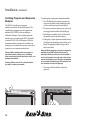
Creating Irrigation Schedules . . . . . . . . . . . . . . . . . . . . . . . . . . . . . . . . . . . . . . . . . . . . . . . 41
Setting the Steps for Each Program . . . . . . . . . . . . . . . . . . . . . . . . . . . . . . . . . . . . . . . . . . . . . . . . . . . . . . . . . . . 42
Setting Up Steps . . . . . . . . . . . . . . . . . . . . . . . . . . . . . . . . . . . . . . . . . . . . . . . . . . . . . . . . . . . . . . . . . . . . . . . . . . . . 42
Inserting a step between two steps . . . . . . . . . . . . . . . . . . . . . . . . . . . . . . . . . . . . . . . . . . . . . . . . . . . . . . . 43
Deleting steps . . . . . . . . . . . . . . . . . . . . . . . . . . . . . . . . . . . . . . . . . . . . . . . . . . . . . . . . . . . . . . . . . . . . . . . . . . . 44
Selecting the Days . . . . . . . . . . . . . . . . . . . . . . . . . . . . . . . . . . . . . . . . . . . . . . . . . . . . . . . . . . . . . . . . . . . . . . . . . . . 44
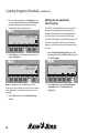
Selecting a Start Time . . . . . . . . . . . . . . . . . . . . . . . . . . . . . . . . . . . . . . . . . . . . . . . . . . . . . . . . . . . . . . . . . . . . . . . . 45
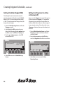
Setting the Water Budget (WB) . . . . . . . . . . . . . . . . . . . . . . . . . . . . . . . . . . . . . . . . . . . . . . . . . . . . . . . . . . . . . . . 46
Setting the Programs for Active or Passive (A/P) . . . . . . . . . . . . . . . . . . . . . . . . . . . . . . . . . . . . . . . . . . . . . . . 46
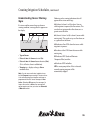
Scheduling to Run on Specific Days and Dates . . . . . . . . . . . . . . . . . . . . . . . . . . . . . . . . . . . . . . . . . . . . . . . . 47
Repeating and pausing programs . . . . . . . . . . . . . . . . . . . . . . . . . . . . . . . . . . . . . . . . . . . . . . . . . . . . . . . . 47
Setting Up an Automatic Test Program . . . . . . . . . . . . . . . . . . . . . . . . . . . . . . . . . . . . . . . . . . . . . . . . . . . . . . . . 48
Operating the Irrigation Programs . . . . . . . . . . . . . . . . . . . . . . . . . . . . . . . . . . . . . . . . . . . . . . . . . . . . . . . . . . . . 49
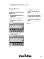
Starting automatic irrigation programs . . . . . . . . . . . . . . . . . . . . . . . . . . . . . . . . . . . . . . . . . . . . . . . . . . . 49
Activating a Decoder in Auto Mode . . . . . . . . . . . . . . . . . . . . . . . . . . . . . . . . . . . . . . . . . . . . . . . . . . . . . . 50
Activating an Irrigation Schedule in Auto Mode . . . . . . . . . . . . . . . . . . . . . . . . . . . . . . . . . . . . . . . . . . . 51
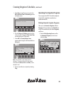
Manually Starting an Irrigation Schedule . . . . . . . . . . . . . . . . . . . . . . . . . . . . . . . . . . . . . . . . . . . . . . . . . 52
Manually activating a Decoder . . . . . . . . . . . . . . . . . . . . . . . . . . . . . . . . . . . . . . . . . . . . . . . . . . . . . . . . . . . 54
Manually stopping an active Decoder . . . . . . . . . . . . . . . . . . . . . . . . . . . . . . . . . . . . . . . . . . . . . . . . . . . . 54
Understanding Sensor Warning Signs . . . . . . . . . . . . . . . . . . . . . . . . . . . . . . . . . . . . . . . . . . . . . . . . . . . . . . . . . 55
Sensing a Short Circuit . . . . . . . . . . . . . . . . . . . . . . . . . . . . . . . . . . . . . . . . . . . . . . . . . . . . . . . . . . . . . . . . . . . . . . . 55
Using the Controller with a PC . . . . . . . . . . . . . . . . . . . . . . . . . . . . . . . . . . . . . . . . . . . . . . 57
Linking your PC and Controller . . . . . . . . . . . . . . . . . . . . . . . . . . . . . . . . . . . . . . . . . . . . . . . . . . . . . . . . . . . . . . . 58
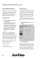
Installing the Rain Bird® MDC PC Software . . . . . . . . . . . . . . . . . . . . . . . . . . . . . . . . . . . . . . . . . . . . . . . . . . . . 59
Setting Up a Communications Link . . . . . . . . . . . . . . . . . . . . . . . . . . . . . . . . . . . . . . . . . . . . . . . . . . . . . . . . . . . 59
4
Contents, continued
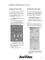
Verifying the Time and Date . . . . . . . . . . . . . . . . . . . . . . . . . . . . . . . . . . . . . . . . . . . . . . . . . . . . . . . . . . . . . . . . . . 61
Controller Status Observation . . . . . . . . . . . . . . . . . . . . . . . . . . . . . . . . . . . . . . . . . . . . . . . . . . . . . . . . . . . . . . . . 61
Using the MDC PC Software . . . . . . . . . . . . . . . . . . . . . . . . . . . . . . . . . . . . . . . . . . . . . . . . . . . . . . . . . . . . . . . . . . 62
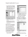
Retrieving the Data . . . . . . . . . . . . . . . . . . . . . . . . . . . . . . . . . . . . . . . . . . . . . . . . . . . . . . . . . . . . . . . . . . . . . . 62
Editing Set-Up Data . . . . . . . . . . . . . . . . . . . . . . . . . . . . . . . . . . . . . . . . . . . . . . . . . . . . . . . . . . . . . . . . . . . . 62
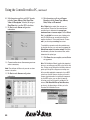
Configuring Sensor Decoder Settings . . . . . . . . . . . . . . . . . . . . . . . . . . . . . . . . . . . . . . . . . . . . . . . . . . . . 64
Configuring On/Off sensor Decoders Alarm Condition . . . . . . . . . . . . . . . . . . . . . . . . . . . . . . . . . . . . 65
Configuring Generic Sensor Decoders . . . . . . . . . . . . . . . . . . . . . . . . . . . . . . . . . . . . . . . . . . . . . . . . . . . . 65
Configuring Flow Sensor Decoders . . . . . . . . . . . . . . . . . . . . . . . . . . . . . . . . . . . . . . . . . . . . . . . . . . . . . . . 66
Main Pump Failure Alarm . . . . . . . . . . . . . . . . . . . . . . . . . . . . . . . . . . . . . . . . . . . . . . . . . . . . . . . . . . . . . . . 66
Erasing the set-up data . . . . . . . . . . . . . . . . . . . . . . . . . . . . . . . . . . . . . . . . . . . . . . . . . . . . . . . . . . . . . . 67
Editing irrigation schedules . . . . . . . . . . . . . . . . . . . . . . . . . . . . . . . . . . . . . . . . . . . . . . . . . . . . . . . . . . 67
Deleting a Schedule . . . . . . . . . . . . . . . . . . . . . . . . . . . . . . . . . . . . . . . . . . . . . . . . . . . . . . . . . . . . . . . . . . . . . 68
Erasing all irrigation schedules . . . . . . . . . . . . . . . . . . . . . . . . . . . . . . . . . . . . . . . . . . . . . . . . . . . . . . . 69
Editing the global water budget . . . . . . . . . . . . . . . . . . . . . . . . . . . . . . . . . . . . . . . . . . . . . . . . . . . . . . 69
Sending Data to the Controller . . . . . . . . . . . . . . . . . . . . . . . . . . . . . . . . . . . . . . . . . . . . . . . . . . . . . . . . . . . 69
Manual Operations . . . . . . . . . . . . . . . . . . . . . . . . . . . . . . . . . . . . . . . . . . . . . . . . . . . . . . . . . . . . . . . . . . . . . . . . . . 70
Starting a Decoder Manually . . . . . . . . . . . . . . . . . . . . . . . . . . . . . . . . . . . . . . . . . . . . . . . . . . . . . . . . . . . . . 70
Starting a Schedule Manually . . . . . . . . . . . . . . . . . . . . . . . . . . . . . . . . . . . . . . . . . . . . . . . . . . . . . . . . . . . . 71
Retrieving Monitoring Information . . . . . . . . . . . . . . . . . . . . . . . . . . . . . . . . . . . . . . . . . . . . . . . . . . . . . . . 72
Failed Decoder List . . . . . . . . . . . . . . . . . . . . . . . . . . . . . . . . . . . . . . . . . . . . . . . . . . . . . . . . . . . . . . . . . . . . . . 72
Creating a Log File . . . . . . . . . . . . . . . . . . . . . . . . . . . . . . . . . . . . . . . . . . . . . . . . . . . . . . . . . . . . . . . . . . . . . . 73
Viewing a Log File . . . . . . . . . . . . . . . . . . . . . . . . . . . . . . . . . . . . . . . . . . . . . . . . . . . . . . . . . . . . . . . . . . . . . . . 73
Backing Up MDC Database . . . . . . . . . . . . . . . . . . . . . . . . . . . . . . . . . . . . . . . . . . . . . . . . . . . . . . . . . . . . . . 74
Restoring Database . . . . . . . . . . . . . . . . . . . . . . . . . . . . . . . . . . . . . . . . . . . . . . . . . . . . . . . . . . . . . . . . . . . . . . 74
Printing Set-Up and Irrigation Data . . . . . . . . . . . . . . . . . . . . . . . . . . . . . . . . . . . . . . . . . . . . . . . . . . . . . . 75
Firmware Upgrade . . . . . . . . . . . . . . . . . . . . . . . . . . . . . . . . . . . . . . . . . . . . . . . . . . . . . . . . . . . . . . . . . . . . . . 75
Exiting the Remote Access Window . . . . . . . . . . . . . . . . . . . . . . . . . . . . . . . . . . . . . . . . . . . . . . . . . . . . . . . 75
Understanding Faults . . . . . . . . . . . . . . . . . . . . . . . . . . . . . . . . . . . . . . . . . . . . . . . . . . . . . . . . . . . . . . . . . . . . . . . . 77
Finding the Cause . . . . . . . . . . . . . . . . . . . . . . . . . . . . . . . . . . . . . . . . . . . . . . . . . . . . . . . . . . . . . . . . . . . . . . . . . . . 77
Troubleshooting . . . . . . . . . . . . . . . . . . . . . . . . . . . . . . . . . . . . . . . . . . . . . . . . . . . . . . . . . . 77
Understanding Basic Troubleshooting Techniques . . . . . . . . . . . . . . . . . . . . . . . . . . . . . . . . . . . . . . . . . . . . 78
Troubleshooting the System . . . . . . . . . . . . . . . . . . . . . . . . . . . . . . . . . . . . . . . . . . . . . . . . . . . . . . . . . . . . . . . . . . 79
Troubleshooting a Field Transmitter (Optional) . . . . . . . . . . . . . . . . . . . . . . . . . . . . . . . . . . . . . . . . . . . . . . . 87
Troubleshooting the Controller’s Internal Parts . . . . . . . . . . . . . . . . . . . . . . . . . . . . . . . . . . . . . . . . . . . . . . . . 88
Replacing The Controller . . . . . . . . . . . . . . . . . . . . . . . . . . . . . . . . . . . . . . . . . . . . . . . . . . . . . . . . . . . . . . . . . . . . 89
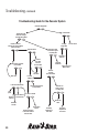
Troubleshooting Guide for the Decoder System . . . . . . . . . . . . . . . . . . . . . . . . . . . . . . . . . . . . . . . . . . . . . . . 90
5
Contents, continued
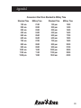
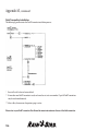
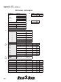
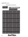
Appendix I . . . . . . . . . . . . . . . . . . . . . . . . . . . . . . . . . . . . . . . . . . . . . . . . . . . . . . . . . . . . . . . 91
Conversion Chart from Standard to Military Time . . . . . . . . . . . . . . . . . . . . . . . . . . . . . . . . . . . . . . . . . . . . . 91
Appendix II . . . . . . . . . . . . . . . . . . . . . . . . . . . . . . . . . . . . . . . . . . . . . . . . . . . . . . . . . . . . . . . 93
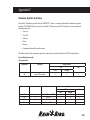
Selecting Electrical Codes for Solenoids . . . . . . . . . . . . . . . . . . . . . . . . . . . . . . . . . . . . . . . . . . . . . . . . . . . . . . . 93
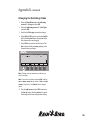
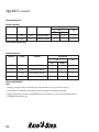
Changing the Switching Codes . . . . . . . . . . . . . . . . . . . . . . . . . . . . . . . . . . . . . . . . . . . . . . . . . . . . . . . . . . . . . . . 95
Appendix III . . . . . . . . . . . . . . . . . . . . . . . . . . . . . . . . . . . . . . . . . . . . . . . . . . . . . . . . . . . . . . 97
Master Valve and Pump Set-up Tips . . . . . . . . . . . . . . . . . . . . . . . . . . . . . . . . . . . . . . . . . . . . . . . . . . . . . . . . . . 97
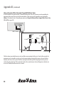
Using a Field Decoder With a Pump . . . . . . . . . . . . . . . . . . . . . . . . . . . . . . . . . . . . . . . . . . . . . . . . . . . . . . 97
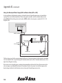
Using a Decoder With a Normally Closed (NC) Master Valve . . . . . . . . . . . . . . . . . . . . . . . . . . . . . . . 98
Using a Decoder and Relay-100 With a Pressure Switch . . . . . . . . . . . . . . . . . . . . . . . . . . . . . . . . . . . . 99
Using the Municipal Water Supply with a Master Valve (NC or NO) . . . . . . . . . . . . . . . . . . . . . . . . 100
Appendix IV . . . . . . . . . . . . . . . . . . . . . . . . . . . . . . . . . . . . . . . . . . . . . . . . . . . . . . . . . . . . . 101
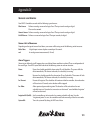
Sensors and Alarms . . . . . . . . . . . . . . . . . . . . . . . . . . . . . . . . . . . . . . . . . . . . . . . . . . . . . . . . . . . . . . . . . . . . . . . . . 101
Sensor Unit of Measures . . . . . . . . . . . . . . . . . . . . . . . . . . . . . . . . . . . . . . . . . . . . . . . . . . . . . . . . . . . . . . . . 101
Alarm Triggers . . . . . . . . . . . . . . . . . . . . . . . . . . . . . . . . . . . . . . . . . . . . . . . . . . . . . . . . . . . . . . . . . . . . . . . . . 101
Alarm Action Type . . . . . . . . . . . . . . . . . . . . . . . . . . . . . . . . . . . . . . . . . . . . . . . . . . . . . . . . . . . . . . . . . . . . . 102
Alarm Action ID . . . . . . . . . . . . . . . . . . . . . . . . . . . . . . . . . . . . . . . . . . . . . . . . . . . . . . . . . . . . . . . . . . . . . . . . 102
Appendix V . . . . . . . . . . . . . . . . . . . . . . . . . . . . . . . . . . . . . . . . . . . . . . . . . . . . . . . . . . . . . .103
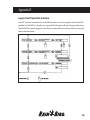
Freedom System Interface . . . . . . . . . . . . . . . . . . . . . . . . . . . . . . . . . . . . . . . . . . . . . . . . . . . . . . . . . . . . . . . . . . 103
FREEDOM™ System Commands . . . . . . . . . . . . . . . . . . . . . . . . . . . . . . . . . . . . . . . . . . . . . . . . . . . . . . . . 103
Appendix VI . . . . . . . . . . . . . . . . . . . . . . . . . . . . . . . . . . . . . . . . . . . . . . . . . . . . . . . . . . . . . 105
Field Transmitter Interface . . . . . . . . . . . . . . . . . . . . . . . . . . . . . . . . . . . . . . . . . . . . . . . . . . . . . . . . . . . . . . . . . . 105
Field Transmitter Installation . . . . . . . . . . . . . . . . . . . . . . . . . . . . . . . . . . . . . . . . . . . . . . . . . . . . . . . . . . . 106
Appendix VII . . . . . . . . . . . . . . . . . . . . . . . . . . . . . . . . . . . . . . . . . . . . . . . . . . . . . . . . . . . . 107
Instructions for Upgrading Existing MDC’s to Version 2.0 . . . . . . . . . . . . . . . . . . . . . . . . . . . . . . . . . . . . . 107
Appendix VIII . . . . . . . . . . . . . . . . . . . . . . . . . . . . . . . . . . . . . . . . . . . . . . . . . . . . . . . . . . . . 109
MDC Controller Information Sheet Descriptions . . . . . . . . . . . . . . . . . . . . . . . . . . . . . . . . . . . . . . . . . . . . . 109
Glossary . . . . . . . . . . . . . . . . . . . . . . . . . . . . . . . . . . . . . . . . . . . . . . . . . . . . . . . . . . . . . . . . 113
Service Information . . . . . . . . . . . . . . . . . . . . . . . . . . . . . . . . . . . . . . . . . . . . . . . . . . . . . . 115
Warranty . . . . . . . . . . . . . . . . . . . . . . . . . . . . . . . . . . . . . . . . . . . . . . . . . . . inside back cover
6
Introduction
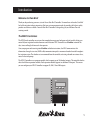
Welcome to Rain Bird
®
Thank you for purchasing your new, state-of-the-art Rain Bird Controller. For more than six decades, Rain Bird
has led the irrigation industry in meeting all of your water management needs by providing the highest quality
products and services available. Your new Rain Bird Controller is designed to give you a lifetime of on-site
watering control.
®
®
®
The MDC Controllers
The MDC line of controllers are systems that completely manage your landscape and turf needs by letting you
control all your irrigation functions from one central location. MDC Controllers use Schedules to control the
days, times and length of time each valve operates.
Once you program and store irrigation Schedules and other instructions, the MDC communicates this
information, through a two-wire (MAXI cable) communication path, to numerous decoders located throughout
the irrigation system. The decoders act on command from the controller, activating solenoids on various valves,
master valves and pumps.
The MDC2 Controller uses a program module, which supports up to 50 (decoder) outputs. The controller also has
slots to hold three expansion modules. Each expansion module supports an additional 50 outputs. This means
you can configure your MDC2 Controller to support 50, 100, 150 and 200 outputs.
MDC
1
Introduction, continued
Special Features
The MDC2 Controller mounts to a wall and has the following special features:
4 Anti-rust, corrosion-resistant design
4 Weather-resistant cabinet allowing you to mount the controller inside or outside
4 Stores up to 10 separate irrigation Programs and 1 auxiliary (non-irrigation) Program (which does not start
pumps)
4 Each Program supports up to 100 Steps (individual commands that complete a Program)
4 Each Program can start up to 6 times a day
4 Each Program runs on a 14-day Schedule
4 Input terminal connections for rain or alarm sensor
4 Output terminals for 3 communications cables
4 Communications cables to support flow and auxiliary sensors
4 Slots provided for 3 expansion modules supporting up to 200 single-output decoders (MDC2)
4 Easy-to-use menu tree system
4 Diagnostics to test decoders, schedules and short findings
4 The option to choose between 5 languages (U.S. English, British English, Spanish, French and German)
4 Backlighting that makes the liquid crystal display (LCD) easy to read
4 A serial communication port and modem allowing you to program the controller from a PC
4 Software to allow for remote programming and monitoring from a PC
2
Introduction, continued
Packing List
Please check to make sure that you have all the items on the list. If any item is missing or damaged, contact your
Rain Bird distributor.
®
1
Pre-assembled Controller in a Plastic Wall Cabinet
2
Keys
1
Installation and Operating Instructions Manual
1
Mounting Template
1
Three-year Warranty Card
1
MDC Software CD
MDC
3
Installation
This chapter of the manual explains how to mount your new MDC2 Controller on the wall, how to connect the
wiring, install program and expansion modules and replace the battery.
Mounting the Controller
Before You Begin
Warning! Before installing your controller, make sure that the area around you is free from dirt and dust
and that your hands and arms are clean. This will avoid contaminating the controller’s internal parts.
Warning! Do not let water or other liquids come in contact with any part inside the cabinet.
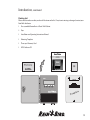
Choosing a location
When choosing the best location to install your wall-mounted controller, please consider the following:
You must install this controller in compliance with local electrical codes.
4 The MDC2 Controller cabinet is water-resistant, so you can mount it inside or outside.
4 Select an area, protected from vandalism, where the user can easily reach the controller. Rain Bird
recommends placing the controller at eye level, in a utility room.
®
Warning! To minimize electromagnetic interference, select a location that is at least 15’(4.6 m) away from
high-draw motors, such as air conditioners, refrigerators or pool pumps.
4 Select a location that has access to 120-Volt AC electrical power (or the proper electrical supply voltage outside
the United States).
4 Mount the controller on a flat, stable, vertical surface. Allow sufficient conduit clearance for the electrical
connections at the bottom of the cabinet.
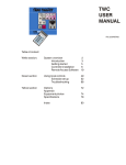
4 Allow 9 1/2” (24.2 cm) minimum clearance for the hinged cabinet door to swing fully to the left.
4 Allow at least 6 1/4” (17.2 cm) minimum clearance above the cabinet door so you can easily remove the hinge
pin to service the controller.
5
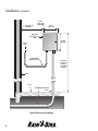
Installation, continued
9-1/2" (24.2 cm)
minimum
6-1/4"
(17.2 cm)
minimum
9-1/2"
(24.1 cm)
Cabinet is
4-3/8" (11.1 cm)
Deep
10-1/4"
(26 cm)
To Fuse
Box
120-Volt AC
Wiring in Conduit
Wall
Floor
Field Wiring in Conduit
Typical Wall-mount Installation
6
Locate for
easy access
and for
comfortable
viewing
Installation, continued
What you will need
Before you begin installation, you may need the following tools and materials:
4 Slotted Head Screwdriver
4 Phillips Head Screwdriver
4 Thin Blade Screwdriver
4 Lineman’s Pliers
4 DBY Connectors
4 Hammer
4 Grounding Strap
4 Two-wire MAXI Cable (#14 AWG wire)
4 Two-wire MAXI Cable (#18 AWG wire)
4 #8 AWG or #10 AWG Bare Ground Wire
4 Tape Measure
4 Wire Stripper
4 Wire Nuts
4 Marking Pencil
4 Electric Drill (or Hammer Drill if installing in masonry or concrete wall)
7
Installation, continued
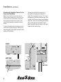
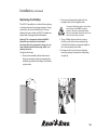
Preparing the Controller Cabinet for the
Power and Field Wires
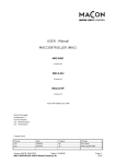
Note: You can remove four knockouts from the
controller cabinet making it easy to route the wires.
You will find two of these knockouts on the back
(for routing wires through a wall) and two on the
underside (for feeding wires through the cabinet’s
bottom).
To tap out a knockout, place the cabinet on a firm
surface with the groove facing you. Work your way
around the groove with a slotted screwdriver, firmly
tapping out the knockout.
BACK
Knockout
BOTTOM
Knockout
8
A hole on the underside of the cabinet fits a 1”
(2.6 cm) PVC male adapter for installing PVC
conduit. You can increase its size to 1 1/4” (3.2 cm)
by tapping out the knockout around the hole. If you
are using #14 AWG wire, or larger, you may need the
larger hole. If you run the wires through the bottom
holes, you will need to install conduits. Slip the
conduit through the hole and secure it with a male
adapter or other conduit fittings.
Installation, continued
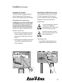
Mounting the Controller on the Wall
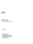
Note: The MDC2 Controller has four mounting holes
on the back on the cabinet—three keyhole slots
near the top and one circular hole at the bottom.
Note: To install the controller on a flat wall surface,
use the left and right keyhole slots at the top of the
cabinet. To install the controller on a narrow stud,
use the center keyhole slot.
1. Place the mounting template onto your
mounting surface. Make sure it is level and
mark the top drill holes. If mounting to a stud,
mark the drill hole in the center of the stud.
Note: The mounting materials and specific screws
you need will vary according to the mounting
surface (i.e., wood, cement, masonry, drywall, etc.)
4. Slide the MDC cabinet over the top screws.
5. If mounting to a stud, swing open the cabinet
door and faceplate. Mark the position of the
bottom drill hole and then lift off the controller.
Do not attempt to drill the bottom hole through
the cabinet.
6. Drill the bottom hole and remount the cabinet.
7. Secure the bottom of the cabinet with a screw,
tightening it all the way.
2. Drill the holes and use the appropriate plugs
or fasteners.
3. Screw in the appropriate mounting screws,
leaving about 3/8” between the screw heads and
wall.
WALL
9
Installation, continued
Connecting the Controller
There are three types of connections you must
make to your MDC2 Controller. They include:
• Connecting to the Two-wire Communications
Cable,
• Grounding the Controller, and
• Connecting to the Main Power Source.
Note: You may also connect an optional sensor,
which prevents irrigation during rainfall or when the
soil is moist.
This section of the manual contains instructions
for all three types of basic connections, and the
optional sensor connection.
Note: If you are installing a field or sensor decoder,
please see the MDC2 and Decoder Installation
poster for more information.
All wiring must be installed and connected in accordance with local
electrical codes.
Note: You can run wires through the holes at the
bottom of the cabinet or through the knockout holes
at the back of the cabinet. If you use the knockout
holes, make sure you seal the unused bottom holes.
If you run the wires through the bottom holes, you
will need to install conduits. Slip the conduit through
the hole and secure it with a male adapter or other
conduit fittings.
10
Connecting to the Two-wire
Communications Cable
Note: You can connect up to three separate
two-wire communications cables (paths). The
communications cable you use must be approved
for underground use. Rain Bird recommends
you use MAXI Cable, #14 AWG as your two-wire
communications cable.
®
Warning! Do not install the communications
cables in the same conduit as the wires to the
Main power source.
To connect the cable,
1. Feed the two-wire communications cable
through the conduit and into the controller.
2. Remove about 6” of the cable’s outer sheathing
and strip about 5/8” of the insulation from the
ends of the two wires.
3. Using a thin blade screwdriver, connect the wire
ends to a set of L1 and L2 terminals.
Tug on the wires to make sure the connections
are tight.
Installation, continued
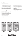
Grounding the Controller
Connecting to the Main Power Source
The MDC2 Controller is equipped with built-in
electrical surge protection. For this system to
function, you must properly ground the controller.
The three Main power input wires for a standard
120-Volt AC transformer are black, white and
green. You will find these wires in the high voltage
compartment in the lower left corner of the
controller cabinet.
Warning! Connect the controller to the
grounding grid using at least a #8 AWG (10 mm)
or #10 AWG (6 mm) bare wire. The wire should
be as short and as straight as possible. You
will void the warranty if you do not ground the
controller to a maximum reading of five ohms.
To connect the ground wire,
1. Loosen the screw on the copper earth ground
terminal and slide the end of the ground wire
into the terminal. Tighten the screw to secure
the wire.
2. Feed the ground wire through the same conduit
you used for the communications cable and
connect it to ground.
To prevent electrical shock, make sure
all supply power is OFF before
connecting these wires. Electrical shock
can cause severe injury or death.
All electrical connections and wiring
runs must be made according to local
electrical building codes.
To feed the power wires,
1. Locate the high voltage compartment cover,
remove the screw and swing open the cover.
11
Installation, continued
2. Feed the Mains 120-Volt AC power wires into the
high voltage compartment through a separate
conduit.
Note: You can also connect the Mains 120-Volt AC
power and transformer wires inside a junction box
located outside the controller cabinet.
OR
Feed the Mains 120-Volt AC power wires through
the 1/4” knockout hole on the back of the cabinet.
You also need to cut out the scored hole in the high
voltage compartment’s fiberboard liner.
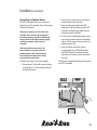
To connect to the Main power source,
1. Strip about 1/2” of the insulation off the ends of
the power wires.
OR
12
2. Using code-approved wire nuts, connect the
black (HOT) wire to the black transformer wire,
the white (neutral) wire to the white transformer
wire and the green (ground) wire to the green
transformer wire.
3. Tug on the connections to make sure they are
tight, then close the high voltage compartment
cover and replace the screw.
Installation, continued
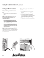
Connecting an Optional Sensor
The MDC2 Controller allows you to connect an
optional sensor. The controller works with any open
or closed switch sensor.
Warning! The wires you use to connect the
controller to the sensor must be approved
for underground use. Rain Bird recommends
using a two-wire #18 AWG (maximum gauge)
cable long enough to easily reach the
controller.
®
2. Using wire nuts, connect the two-wire cable to
the sensor wires inside a valve box.
3. Protect all underground splices with DBY
connections. Insert the wire nuts into the DBY
connectors and close the gap tightly. Place the
connectors inside the valve box.
4. Run the two-wire cable leading from the sensor
wires through a conduit and into the controller
cabinet. Use the same conduit you used for the
communications cable.
Warning! Install the sensor wire in the
same conduit you use for the two-wire
communications cable and ground wire.
The conduit for the power wires should
only contain the power wires.
5. Using a thin blade screwdriver, connect
the sensor cable wires to SENSOR terminal 1
and SENSOR terminal 2 inside the controller.
Tug on the wires to make sure the connections
are secure.
To connect the sensor’s wires to the controller,
You have now completed mounting and wiring your
new MDC2 Controller.
1. Remove about 6” of the cable’s outer sheathing
and strip about 5/8” of the insulation from the
ends of the two wires.
13
Installation, continued
Installing Program and Expansion
Modules
The MDC2 Controller uses a program
module that controls 50 (decoder) outputs. The
controller also supports up to three expansion
modules (MDC/M50D), each controlling an
additional 50 outputs. So, by adding expansion
modules, you can configure the MDC2 Controller
to control 50, 100, 150, or 200 outputs. 200 is the
maximum number of outputs the controller can
manage in any combination over one, two or three
separate two-wire communications lines.
Warning! When working with any program or
expansion module, always use a grounding
strap to avoid electrostatic discharge, which can
damage the modules.
Warning! Always turn off the controller before
you add or remove any module.
To add or replace a program or expansion module,
1. Use a Phillips head screwdriver to remove the
two screws and lock washers holding the guide
rail. Be careful not to lose the lock washers.
2. To remove a worn out module, grasp it by its tab
and wiggle it back and forth while pulling up.
3. Hold the new module by its tab, so the back of
the module faces the top of the cabinet.
4. Firmly plug a 10-pin expansion module into one
of the three corresponding sockets on the circuit
board. The program module is larger and fits
only in one socket.
Warning! When plugging a program or expansion
module into an MDC socket, please note its
orientation. Make sure the back of the module’s
mini circuit board is facing the top of the cabinet
and not the display screen. Plugging the modules
in backwards will not damage the controller, but
the controller will not work properly.
5. Once you install the modules, replace the
guide rail.
14
Installation, continued
Replacing the Battery
The MDC2 Controller has a built-in lithium battery
to backup and store the program memory. During
normal use, the battery should last for 10 years.
Replace the battery when the MDC2 Controller no
longer holds the programmed information.
Warning! The components inside the MDC2
Controller are sensitive to electrostatic
discharge. By using a grounding strap, you can
help avoid electrostatic discharge, which can
damage the units.
To replace the battery,
1. Remove the controller cabinet door from its
hinges by opening the door, then pushing the
metal pin up and out of the hinge. Set the door
and pin aside.
2. Unscrew and remove the faceplate. Set the
faceplate aside. Set the faceplate aside.
To prevent electrical shock, turn off the
controller and shut OFF all supply power to the unit at the Main power
before proceeding. Electrical shock can cause severe injury or death.
3. Using a Phillips head screwdriver, remove
the five screws, lock washers and metal clip.
Carefully lift the display and control module as
far as the connecting wires allow.
4. Disconnect the two-wire harness from the
board by grasping the connector and pulling
straight up.
MDC
15
Installation, continued
5. Open the locking tabs on the three ribbon
cables by pushing the tabs away from the cables.
Disconnect the ribbon cables by grasping the
wide sides of the connectors and gently pulling
the connector away from the board. Set the
module aside.
6. Using a thin blade screwdriver, gently pry the
lithium battery out of its compartment and
replace it with a new battery, positive side
facing up.
Warning! Dispose of the depleted battery in
accordance with local regulations.
!
If you mistreat the battery, it may
explode. Do not recharge, disassemble
or dispose of in fire.
To reassemble the controller,
1. Reconnect the three ribbon cables by firmly
pushing each connector into their slots on
the board. A small tab on the side of the
connector slides into a slot on the socket, so
each connector fits only one way. Firmly push to
engage the locking tabs.
2. Plug in the two-wire harness into its
corresponding slot on the board. It fits only
one way.
3. Reposition the display and control module and
replace the screws, lock washers and clip.
4. Replace the controller’s faceplate.
5. Screw on the faceplate.
6. Turn on the Main power supply to the controller
and turn on the controller.
Note: When you change the battery, you will need
to reprogram the MDC2 Controller.
16
Programming and Operation
Using the buttons on the controller, you can set up the MDC2 Controller to operate automatically. You can also
run the controller manually without changing the Programs you have set.
This chapter shows you how to use the controller’s buttons and gives you step-by-step instructions for setting up
the controller to suit your needs.
17
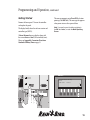
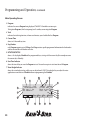
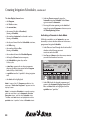
Programming and Operation, continued
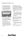
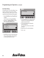
Familiarizing Yourself with the MDC2 Controller
Before beginning to program or operate your MDC2 Controller, take a moment to familiarize yourself with
the controller. Note that the location of the ON/OFF switch is behind the removable panel. Once you turn the
controller on, you can use the buttons to guide you through different display screens and functions on the (Liquid
Crystal Display) LCD.
Most screens show a row of labels at the bottom. These labels indicate the specific function of the buttons under
each label. As the labels change from one screen to the next, so does the function of the buttons. Labels with tabs
contain submenus.
A backlight lights the display while you operate the buttons. Once you stop, the backlight remains on for about 70
seconds then turns off. The information is still on the display, but the display is not lit. Pressing any button turns
the backlight on again.
Note: You must first turn on the backlight (press a button) before you can operate the controller.
MDC
Program 1
Total
2 MTWTFSSMTWTFSS
Run every 5. Day
First 2002-03-26
Sch
18
Sch
Sched
0:05
09:48:00
(2) 13:50
100% A
Repeat 6 times
Pause: 1 Min.
Menu
Auto
Manual
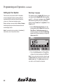
Programming and Operation, continued
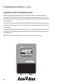
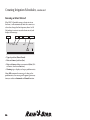
Getting Started
Remove the lower panel. Turn on the controller
and replace the panel.
The display briefly shows the software version and
controller type (MDC2).
The message prompts you to Press OK (the button
pointing to the OK label). This message also appears
when power returns after a power failure.
Note: You need to press the button pointing to
the OK label twice, to reach the Main Operating
Screen.
A Power Returned message displays along with
the current date and time (24 hour military time).
Please see Appendix I: Conversion Chart from
Standard to Military Time on page 91.
MDC
Power Returned (Press OK Twice)
16:16:10
2002 - 03-26
16:16:10
OK
19
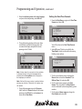
Programming and Operation, continued
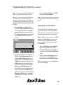
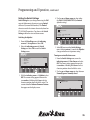
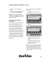
Main Operating Screen
1. Program
indicates the current Program being displayed. The MDC2 Controller can store up to
10 irrigation Programs (which start pumps) and 1 auxiliary or non-irrigation Program.
2. Total
indicates the total irrigation time, in hours and minutes, you scheduled for that Program.
3. Current Time
shows in 24-hour military time.
4. Step Number
each Program supports up to 100 Steps. Each Step contains specific programmed information for the decoders
and the run time for each decoder and valve.
5. MTWTFSSMTWTFSS
shows a 14-day display Schedule of the programmed days, starting with the current day (this example assumes
the current day is Monday).
6. Start Time Indicator
shows the time of day you want the Program to start. You can have up to six start times for each Program.
7. Water Budget Indicator
shows the water budget setting, which you can adjust from 0-250%. Water budget lets you adjust the water
application or run times in a Schedule without reprogramming the Schedule.
3
2
1
6
5
8
4
9
11
Program 1
Total
2 MTWTFSSMTWTFSS
Run every 5. Day
First 2002-03-26
7
10
Sch
Sch
Sched
Menu
Auto
Manual
13
12
14
20
0:05
09:48:00
(2) 13:50
100% A
Repeat 6 times
Pause: 1 Min.
15
16
17
18
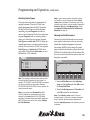
Programming and Operation, continued
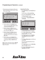
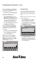
8. Active/Passive
indicates whether a current Program is Active (A) or Passive (P).
9. Run Every
shows the selected irrigation days, from 1-14.
10. Repeat
2
1
5
shows how many times (up to 99 times) irrigation Programs Repeat.
11. First
3
6
shows the year, month and day a Schedule begins.
Program 1
Total
2 MTWTFSSMTWTFSS
Run every 5. Day
First 2002-03-26
12. Pause
0:05
8
09:48:00
shows
how
Program to
Pause between Repeat Programs, before resuming
(2) 13:50
100%
Program
1 manyAminutes
Total you want a0:05
09:48:00
with2 6the
next Program.
Repeat
times
MTWTFSSMTWTFSS
(2) 13:50
100% A
7 Repeat 6 times
10 Pause: 1 Min.
Program 1
Total
0:05
09:48:00
“sprinkles”
when
an
irrigation
Schedule is running.
2 MTWTFSSMTWTFSS
(2) 13:50
100%
13 A
Sched
Menu
Auto
Manual
Sch
Sch
Run every 5.
Day
Repeat
6
times
14. Sch
(Search) Menu
Labels Auto
Sched
Manual
Sch
First 2002-03-26
Pause: 1 Min. 12
Program 1
Total
0:05
09:48:00
use (2)
the13:50
buttons associated
2 MTWTFSSMTWTFSS
100% A with the Sch labels to move up and down through the 11 stored Programs.
Run every 5. Day 15. Repeat(Schedule)
6 times Label
Sched
Manual
Sch 15 Sch16
14
17 Menu
1 18
Min. Auto
Program 1First 2002-03-26
Total
0:05 Pause:
09:48:00
use
the
button
associated
with
the Sched label to set up specific irrigation Schedules.
2 MTWTFSSMTWTFSS
(2) 13:50
100% A
Run every 5. Day
Repeat
6
times
16. Label
Sched
Manual
Sch
Sch
First 2002-03-26
Pause:Menu
1 Min. Auto
Total
TFSSMTWTFSS
Sch
Sch
y 5. Day
2-03-26
Sch
Sched
Pause:
Run1 Min.
every 5.
Day
13. Sprinkler
Icon
First 2002-03-26
use the button associated with the Menu label to enter the Main Menu.
0:05
09:48:00
(2) 13:50
100%
Auto A Manual
Label
Sched
Menu17.
Repeat 6 times
Pause: 1 Min. use the button associated with the Auto label to set the controller to the Auto mode. A menu displays allowing
you to Pause the irrigation Schedule and manually start the decoders.
Menu
Auto18. Manual Label
use the button associated with the Manual label to enter a menu where you can manually start irrigation
programs or decoders and Pause a running Program.
21
Programming and Operation, continued
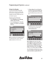
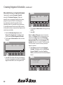
Setting Up Your System
Selecting a Language
The first time you turn on the MDC2 Controller,
you must program into your system specific setup information (decoder and solenoid numbers,
sensors, etc.) about your irrigation system.
The default language is English (US). However, you
can choose between English (UK) (British spelling
and m3/h ––cubic meters per hour setting), English
(US) (American spelling and GPM––gallons per
minute setting), German (m3/h), Spanish (m3/h) or
French (m3/h).
Before you begin, you may need to Select a Country
(indicating language and unit of measure) to read
on the display screen.
Note: Pressing the button pointing to the minus (-)
label returns you to the previous menu.
1. From the Main Operating Screen, press the
button pointing to the Menu label to reach the
Main Menu. An indicating arrow points to
the menu category. You control the indicating
arrow with the buttons pointing to the up and
down arrow labels.
2. Move the indicating arrow to 1. Set-up Data
and press the button pointing to the OK label.
Note: Pressing the button pointing to either the up
or down arrow labels changes the direction of the
double arrow label. The double arrow label lets
you quickly scroll through the categories.
22
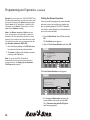
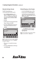
Programming and Operation, continued
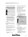
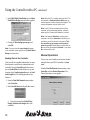
3. Move the indicating arrow to 10. Select Language
and press the button pointing to the OK label.
5.
6.
7.
8.
9.
10.
Sensors
Sensor Decoder
Non-Water Window
Switch Settings
Erase All
Select Language
English (US)
Danish
Swedish
German
Italian
Spanish
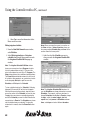
1. From the Main Menu, navigate to 2. Date/Time
Formats and select OK.
11:03 AM
1.
2.
3.
4.
5.
4. Using the buttons pointing to the up or down
arrow labels, scroll to the language you want
to read on the display and press the button
pointing to the OK label.
2.
3.
4.
5.
6.
7.
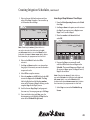
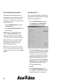
Setting the Date/Time Formats
*** Main Menu ***
Set-up Data
Date/Time Formats
Setting Date/Time
Test
Log Data
08:27 AM
You will be taken to the Date/Time Formats
menu.
2. Select OK again. The first active field is the
Time Hours, which is indicated by alternating
blinking arrow markers.
11:04 AM
Note: It takes about five seconds for the controller
to change the text to the new language before
returning to the Set-up Data menu, displayed in
the language you selected.
Note: Wait until the new country is updated before
pressing any buttons. Otherwise, the country may
not update.
5. Using the button pointing to the Up arrow
label, scroll to 11. Return and press the button
pointing to the OK label, or select minus(-) to
return to the Main Menu.
*** Date / Time Formats ***
Time hours: >24<Hours
Date Format: DMY
.
Year delim:
08:31 AM
3. Use the up and down arrows to change the
Hours format to be either Standard (12) or
Military Time (24) and select OK.
4. Use the down arrow to move to the Date
Format. The active field is the Date Format,
which is indicated by alternating blinking arrow
markers.
5. Use the up and down arrows to change the
Date Format and select OK.
23
Programming and Operation, continued
6. Use the down arrow to move to the Year
Delimited.
7. Use the up and down arrows to change the
Year Delimited format and select OK.
8. Press – to exit Date/Time Formats screen.
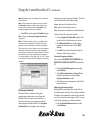
Setting the Date and Time
1. From the Main Menu, move the indicating
arrow to 2. Setting Date/Time and select
OK. The first active field is the year, which
is indicated by alternating blinking arrow
markers.
>2002<-03-26
20:33:58
Tuesday (9)
20:33:58
4. Scroll up or down to the correct day. OK accepts
the change and moves the markers to the hour,
which reads in 24-hour military time. Please see
Appendix I: Conversion Chart from Standard
to Military Time on page 91.
Note: The year, month and day you choose directly
affects the day of the week (Monday-Sunday).
Changing any of those variables also changes the
day of the week. The number next to the day of
the week represents the specific day in the 14-day
calendar.
5. Scroll up or down to the correct hour. OK
moves the markers to the minutes. Change
the minutes the same way then move to the
seconds. OK locks in the new date and time and
returns you to the Main Menu.
2002-03-26
OK
–
20:33:>58<
Tuesday (9)
OK
2. Use the up and down arrows to change the
year.
Note: The double arrow label lets you move
through the date and time quickly. Pressing the
button pointing to the double arrow label once
increases or decreases the date and time by five
digits. To switch the direction of the double arrow
label, press the button pointing to the up and down
arrow labels. Holding in the button pointing to the
double arrows lets you scroll through the numbers
quickly.
3. OK moves the blinking markers to the month.
Scroll to the correct month and select OK to
move the markers to the day.
24
20:33:58
–
Programming and Operation, continued
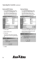
Selecting Valve Types
®
Valve types refer to the electric requirements of
magnetic solenoids. There are 10 Valve Types
already programmed into the MDC2 Controller.
The first five valve types are used by decoders
controlling irrigation Programs and will start
master valves and pumps. The last five control nonirrigation Programs (such as activating auxiliary
alarms, etc.) and will not start pumps. Irrigation
valve types use switch code 59F350. If setting up a
normally open master valve that needs to close on
an alarm, the switch code is 39F350. Non-irrigation
valve types use a switch code of 3FFA20 when
using a relay. These default switch codes are used
for Rain Bird 24 VAC solenoids.
®
Valve Types
1. 59F350
2. 59F350
3. 59F350
4. 59F350
5. 59F350
1
2
1
1
1
Note: If your system operates solenoids that are
not Rain Bird , do not change the default switch
codes before verifying if the solenoids open. If the
solenoids do not open, you may need to change the
activation time and/or holding voltage. Please
see Appendix II: Selecting Electrical Codes for
Solenoids on page 93.
Naming the Field Decoders
You must give each field decoder in your system a
name (up to six characters) so that you can easily
identify that decoder and pinpoint its location.
For example, MAPLE1 (or the shorter M1) could
represent the first decoder facing Maple Street and
ELM5 (or E5) could identify the 5th decoder on Elm
Street. It is easier if you make the name as short and
descriptive as possible.
14:02:28
Decoders
1. –
OK
1
14:02:30
0
–
OK
Note: The number of solenoid (valve) outputs varies
with the Rain Bird Decoders in your system. For
example, FD-102TURF and FD-202TURF can operate
one or two solenoids on each output. Whereas
FD-401TURF and FD-601TURF can only operate one
solenoid on each output.
–
®
Note: If your system uses Standard Rain Bird
24 VAC solenoids, do not change any of these
settings. For the New Rain Bird 24 VAC (White
strip wires) solenoids the recommended settings are
59F370. Please move to the next section, Naming
the Field Decoders.
®
®
1. From the Main Menu, move the indicating
arrow to 1. Set-up Data and select OK to reach
the Set-up Data Menu.
2. Move the indicating arrow to 2. Decoders and
select OK to reach the list of decoders.
Note: The indicating arrow points to the first
available space. If you want to change information
about a specific decoder already programmed,
move the indicating arrow to the decoder you want
to change.
25
Programming and Operation, continued
3. Select OK to add or change a decoder. The
screen now shows four columns or fields with
the titles: Name; Type; Address; Booster and
Flow. A pair of markers points to the Name
field. Use the buttons pointing to the left and
right arrow labels to move the markers from
one field to the next and back again.
Name
>
<
Type
1
Address
0
Bst
Flow
0
OK
12:27 PM
Finish
4. Position the markers under Name and select
OK to activate the Name field. The left and
right arrow labels now switch to up and down
arrows and the two markers alternate blinking,
indicating the field is active.
5. Use the up and down arrows to change each
character one at a time, from left to right. A
blinking box shows the position of the first
character you are changing. The box disappears
when you begin scrolling through the characters.
An arrow then, points to the character you are
changing.
26
Note: The double arrow label lets you move
through the alphanumeric characters quickly.
Pressing the button pointing to the double arrow
label one time increases or decreases the characters
by five numbers or letters. To switch the direction of
the double arrow, press the button pointing to the
up and down arrows. Holding in the button pointing
to the double arrows quickly scrolls through the
characters.
6. Change each character one at a time. OK
accepts the change and moves to the next space.
Continue to select OK until the markers stop
blinking, deactivating the field. The up and
down arrow labels will also switch to left and
right arrow labels.
Note: The controller will not allow you to enter a
duplicate name. If you do, the message Decoder
already exists appears briefly and the controller
returns you to the beginning of the field.
Note: Selecting minus (-) while you are still in an
active field cancels the changes you made and
returns the field to non-active.
7. Move the markers to the Type field. Here, you
will select the type of valve (solenoid) connecting
to the decoder.
Note: The decoder’s Type correlates directly to the
valve type used to set the switch codes.
Programming and Operation, continued
8. Select OK to activate the field, and then scroll
through the choices to either an irrigation
valve—values 1-5—or a non-irrigation valve—
valves A-E. OK accepts the valve Type.
Name
E5
Type
>4<
Address
0
Bst
OK
Flow
15:04:10
OK Finish
–
Note: The controller will not allow you to enter a
duplicate Address. If you try, the message Address
already used appears briefly and the controller
returns you to the beginning of the field.
11. Select OK to select the Address and move the
markers to the Booster (Pump) field.
Note: If the solenoids connected to the decoder
use Booster pumps to start irrigation, you must
associate the Booster pump number to the decoder.
12. Select OK to scroll between Booster Numbers.
Once the desired Booster is selected, move the
markers to the Flow field.
9. Select OK to deactivate the Type field and move
the markers to the Address field. OK activates
the Address field.
Name
E5
Type
4
Address
40216
Note: The Address is the REC. No. (Record
Number) for each decoder and solenoid connection
in your system. You will find this number on the
decoder, which should also be recorded on the
irrigation drawings.
10. Scroll up or down to enter the complete 3-, 4or 5-digit Address (REC. NO.). OK accepts the
number.
Name
E5
Type
4
Address
>40216<
Bst
OK
Flow
15:04:10
0 OK Finish
–
13. Select OK to activate the Flow field and then
scroll up or down. The feature lets you assign
flow values that are used for SEUF (Seek and
Eliminate Unexpected Flow) (see pg. 65).
Flow
15:04:10
OK Finish
Name
E5
OK
Bst
>2<
Type
4
Address
40216
Bst
2
Flow
15:04:10
>30< OK Finish
–
OK
–
14. Select OK once the flow has been set and then
move the markers to the OK field to return to the
decoder listing and continue naming decoders.
27
Programming and Operation, continued
Note: Rain Bird decoders that have more than
one output, (FD-202TURF, FD-401TURF and
FD-601TURF) are considered multiple decoders.
You must list the separate Address (REC. NO.)
for each solenoid/master valve connection (i.e.,
brown 40216, red 40217, etc.) Treat each Address
(REC. NO.) as a separate decoder and give each a
separate name.
®
15. Once you identify each decoder in your
irrigation system, move the markers to Finish
and select OK to return to the Set-up Data
menu.
Decoders Failed
This is a list of valve decoders that have failed due to
triggering SEUF (Seek and Eliminated Unexpected
Flow) and have been blacklisted. A decoder on the
list will not be activated during irrigation.
1. From the Main Menu, select 1. Setup Data and
then select OK. The Setup Data Menu appears.
2. Select 3. Decoders Failed to conduct an audit of
your valves.
1.
2.
3.
4.
5.
** Set-up Data Menu ***
Valve Types
Decoders
Decoders Failed
Pumps/Master Valves
Sensors
11:23 AM
Any valve decoders that have caused SEUF and are
blacklisted shall be listed on the display window.
If any of them have been found to be working
properly or have been fixed, the user must take
them off of the black list for the valves to run again.
28
Entering the Pump/Master Valve
Information
The MDC2 Controller supports master valves,
master pumps and up to nine booster valves
or pumps. Rain Bird recommends you use one
Relay-100 pump start relay for each pump in your
system. However, in place of a pump start relay,
your irrigation system may start pumps using a field
decoder plus an external pressure switch, or use a
master valve with a field decoder. For the controller
to recognize and associate a field decoder to the
master valve and pumps your system uses, you
must program in the decoder’s Address and verify
or change the switch code.
®
1. From the Main Menu, move the indicating
arrow to 1. Set-up Data and select OK.
2. Move the indicating arrow to 4. Pumps/Master
Valves and select OK to reach the Pumps
screen. It lists one Master pump or valve and
nine Booster pumps and their switch codes.
Pumps / Master Valves
1. Master 4FFA20 0
2. Boost1 4FFA20 0
3. Boost2 4FFA20 0
4. Boost3 4FFA20 0
5. Boost4 4FFA20 0
Pause
12:29 PM
OK
3. Move the indicating arrow to 1. Master, and
select OK. The screen now shows 3 fields with
the titles: Pump; Switch; Address and On and
Off. A pair of markers points to the Switch field.
Programming and Operation, continued
Note: If your system uses Rain Bird Decoders and
Relay-100, change the Switch Code to 49F390.
7. Move the markers to Finish and select OK to
return to the Set-up Data Menu.
Note: If your system’s water supply feeds directly
to a master valve, or if the system uses field
decoders or pressure switches to start pumps, you
may need to change the switch code. Please see
Appendix III: Master Valve and Pump Set-up Tips
on page 97.
Note: To deactivate a pump/master valve for repair
or maintenance procedures, change the address to
zero (0).
®
4. Move the markers to the Address field and
select OK. The left and right arrow labels now
switch to up and down and the two markers
alternate blinking, indicating an active field.
5. Use the up and down arrows to enter the field
decoder Address marked on the irrigation
drawings.
Pump
Master
Switch
4FFA20
Address
> 284<
On
0
Off
10
OK
12:31 PM
Finish
Activating Rain or Alarm Sensors
The Rain Bird MDC2 Controller has one sensor
input allowing you to install an optional rain or
alarm sensor. Once you install the sensor, you must
change the sensor status from Passive to Active.
®
Note: The MDC Controller supports only one Rain
Sensor or one Alarm Sensor. Activate only one
sensor leaving the other Passive. Setting both
sensors as Active actually changes the status of
both to Passive.
1. From the Main Menu, move the indicating
arrow to 1. Set-up Data and select OK.
2. Move the indicating arrow to 5. Sensors and
select OK to reach the Rain and Alarm Sensor
screen.
6. OK accepts the Address and the markers stop
blinking. The up and down arrow labels also
change to right and left arrows. The next set
of options let you enter On and Off delays for
a MV/Booster activation or deactivation . The
On Delay means that the start will be delayed
XX seconds after decoder activation. The Off
Delay means the MV/Booster will remain
activated XX seconds after deactivation of the
decoder. This prevents the MV/Booster from
stopping between two steps. To enter additional
Booster pump Addresses, move the markers
to the OK field and select OK to return to the
Pumps screen.
3. If your system uses a Rain Sensor, press the
buttons pointing to the arrow labels and
change sensor status from Passive to Active.
Note: If your system does not use a Rain Sensor,
keep the status Passive.
29
Programming and Operation, continued
4. Select OK to move the markers to the Alarm
Sensor field.
5. If your system uses an Alarm Sensor, change
the status from Passive to Active.
Rain Sensor
Passive
Alarm Sensor
>Active<
OK
14:02:30
–
Setting Up a Sensor Decoder
The MDC2 Controller can control a variety
of sensors (Flow, On/Off, Generic), which are
powered by a Sensor Decoder through the two-wire
communications cable.
Note: Please refer to Appendix IV for detailed
information about the terms and units of measure
mentioned in this section.
Programming a Sensor Decoder
1. From the Main Menu, select 1. Set-up Data and
select OK.
6. Select OK to lock in your setting and return to
the Set-up Data menu.
The Set-up Data Menu appears.
2. Move the indicating arrow to 6. Sensor Decoder
and select OK to reach Sensor Decoders screen.
** Sensor Decoders
SD1
Gen.
SD2
NA
SD3
NA
SD4
NA
SD5
NA
1.
2.
3.
4.
5.
**
50000
50001
50002
50003
50004
12:33 PM
3. Move the indicating arrow to any desired sensor
row and select OK.
The Sensor Decoder Set-up screen appears.
30
Programming and Operation, continued
4. Select OK and the blinking markers are
positioned under Name.
** Sensor Decoder Set-up **
Name
Type Addr.
@
Val
Units Sum
>SD1< Flow 50000
20
100 mA
NA
Alarm
Cond. Limit
Action Obj.
Obj. ID
1.
NA
100
Deact Decod
All
2.
Below 12
Deact Decod
All
5. Select OK to activate the Name field. Use the up
and down arrows to change the default decoder
name. Select OK to store the name.
You will notice that the up and down arrows
switch to the left and right arrows to facilitate
the navigation through the configuration
parameters.
6. Move the markers to the Type field and activate.
Use the up and down arrows to set the decoder
type and select OK to save it.
Note: For Flow Sensor Decoders, Flow Definition
allows you to program a Rain Bird® SD-210TURF
Sensor Decoder to the type of flow sensor your
system uses - either digital (pulse output) or analog
(4-20 milliamps). To establish a conversion ratio, the
controller uses to calculate the flow, you only need
to program the flow output and sensor output.
Rain Bird® recommends you enter the maximum
flow, which determines the pulse type.
Note: Digital (pulse output) flow sensors are
most common. Please see the manufacturers’
specifications to determine the sensor type,
maximum flow and sensor output.
7. Move the markers to the Address field and
activate. Use the up and down arrows to set the
decoder address and select OK to save it.
8. Move the markers to the @ field and activate.
Use the up and down arrows to set the @ value
and select OK to save it.
9. Move the markers to the Value field and
activate. Use the up and down arrows to set the
value and select OK to save it.
10. Move the markers to the Units field and activate.
Use the up and down arrows to choose the
units and select OK to save it.
Note: Choose Pulse/10s if your digital flow sensor
uses a higher pulse rate (30-200 pulses per second)
and counts the number of pulses in 10-second
intervals. Choose mA if you are using an analog flow
sensor.
11. Move the markers to the Sum field and activate.
Use the up and down arrows to choose either
Yes or No and select OK to save it.
Now, it is time to define the alarm conditions.
This feature allows you to set specific alarm
limits when the controller is in the Auto mode.
Once input from the sensor decoder goes
beyond the set limit (which can occur if a valve
opens to a broken pipe), the controller turns off
all active decoders, displays and logs an alarm.
Note: For Flow Control set as below condition
and alarms management the following should be
considered:
1.When the flow has a transition from a value above
the limit to below an alarm will trigger.
2.If no decoders are running for a period of time the
MDC will be in non-irrigation mode and thus look
for leak flow if set up to do so.
31
Programming and Operation, continued
3.When decoders are started again it will then look
again for a transition from above the limit to below
and an alarm will trigger.
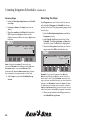
Setting Up Sum Flow Alarms
1. From the Main Menu, choose Set-up Data and
select OK.
You will be taken to the Set-up Data Menu.
** Sensor Decoder Set-up **
Name
Type Addr.
@
Val
Units Sum
SD1
Flow 50000
20
100 mA
NA
Alarm
Cond. Limit
Action Obj.
Obj. ID
1.
>Above< 100
Deact Decod
All
2.
Below 12
Deact Decod
All
12. Move the markers to the Condition field and
activate. Use the up and down arrows to choose
a threshold and select OK to save it.
13. Move the markers to the Limit and activate.
Use the up and down arrows to set the numeric
limit value and select OK to save it.
14. Move the markers to the Action and activate.
Use the up and down arrows to decide what
shall happen when the alarm occurs and select
OK to save it.
15. Move the markers to the Condition field for
the second alarm definition and repeat steps 12
to 14, skipping the Obj. and Obj. Id fields (for
now).
Note: Choosing a decoder that operates a Normally
open Master Valve shuts off the complete water
supply to the system.
2. Navigate to 6. Sensor Decoders and select OK.
The Sensor Decoders list appears.
3. Navigate to 11. ** Setup sum flow alarms **
and select OK.
6. SD6
Gen.
50000
7. SD2
Flow
50001
8. SD3
OnOff
50002
9. SD4
Flow
50003
10. SD10
Gen.
50000
11. ** Setup sum flow alarms **
09:02 AM
OK
The Setup sum flow alarms screen appears.
4. Use the up and down arrows to enable Master
Pump Flow (MPF) and select OK.
5. Use the right arrow to move to the Min flow
when pump active field and select OK to
activate it.
6. Use the up and down arrows to set the flow rate
and select OK.
Now, you are going to define alarms for your
irrigation system.
7. Use the right arrow to move to the Alarm Type
field and select OK to activate it.
8. Use the up and down arrows to choose the
Alarm Type and select OK.
32
Programming and Operation, continued
9. Use the right arrow to move to the Limit field
and select OK to activate it.
10. Use the up and down arrows to set the limit and
select OK.
11. Use the right arrow to move to the second
alarm field and select OK to activate it.
12. Use the up and down arrows to choose between
the Leak and Disable and select OK.
Note: If you choose Disable, select OK and then
select - to exit the screen.
13. If you choose Leak, select OK.
14. Use the right arrow to move to the Limit field
and select OK to activate it.
15. Use the up and down arrows to set the limit and
select OK.
16. Use the right arrow to move to the Action field
and select OK to activate it.
17. Use the up and down arrows to decide what
action you want to take place if the leak
threshold is reached and select OK.
18. Use the right arrow to move to the Object field
and select OK to activate it.
19. Use the up and down arrows to choose amongst
Decoder, Schedule or Pump to be affected by the
defined alarm condition and select OK.
20. Use the right arrow to move to the Object ID
field and select OK to activate it.
21. Use the up and down arrows to choose the
specific Decoder, Schedule or Pump to be
affected by the defined alarm condition and
select OK.
22. Select - to return to the Main Menu.
Setting up an auxiliary sensor
An auxiliary sensor works with rain or alarm
sensors. If the rain sensor is installed far from the
controller or if your system uses a pump alarm,
you will also need an auxiliary sensor activated by
a sensor decoder. Remember, auxiliary sensors
can only tell if a switch is open or closed. Once an
auxiliary sensor activates, irrigation stops.
1. From the Sensor Decoder menu, move the
indicating arrow to 5. Aux. Sensor Decoder
Address and select OK. The two alternating
blinking markers indicate the Sensor Decoder
Address field is ready for you to program in the
Address.
2. Use the up and down arrows to match
the Decoder your system is using for the
Auxiliary Sensor.
Note: The Address should be recorded on the
irrigation drawings.
3. Select OK to store the Address and move the
markers to the Active field. A blinking black box
indicates the field is ready for you to program.
Not Install is the default setting.
4. Use the up and down arrows to select either
Normally open or Normally closed.
Note: Select Normally open if the auxiliary sensor
is open all the time. Select Normally closed if the
auxiliary sensor opens only when it receives a signal.
5. Select OK to return to the Sensor Decoder
menu.
6. Moving the indicating arrow to 6. Return, and
selecting OK, or selecting minus (-) returns you
to the Set-up Data menu.
33
Programming and Operation, continued
Non-Water Window
It is possible to enter a “Non-Water Window” where
irrigation is inhibited. This means the schedules
will run but the decoders will not activate. To select
a specific time frame that does not allow irrigation:
1.
2.
Non-Water Window
From: >12<00 AM
To: 06:30 AM
08:48 AM
1. From the Main Menu, choose Set-up Data and
select OK.
You will be taken to the Set-up Data Menu.
2. Navigate to 7. Non-Water Window and select
OK. The Non-Water Window appears.
2.
3.
4.
5.
6.
7.
Decoders
Decoders Failed
Pumps/Master Valves
Sensors
Sensor Decoder
Non-Water Window
08:41 AM
4. Use the up and down arrows to change the hour
and select OK. The alternating blinking arrow
markers move to the minutes.
5. Use the up and down arrows to change the
minutes and select OK.
Now, you need to set the non-water window
ending time.
6. Repeat steps 4 and 5 to set the ending time.
7. Select - to exit.
3. Select OK to activate non-watering starting time.
The active field is the hour, which is indicated
by alternating blinking arrow markers.
34
Programming and Operation, continued
Setting the Switch Settings
Switch Settings lets you change from using the Full
range of alphanumeric characters to using limited
characters (to name field decoders.) The limited
characters match the sixteen character keyboard on
FT-210 Field Transmitters. You also use the Switch
Setting to define the rain and alarm sensors.
4. Use the up and down arrows to select either
the Full or 1234567890CTFGV (the limited
alphabet setting).
Alphabet
> 234567890CTFGV<
12:36 PM
Versions:
Firmware 1.26b4 MDC-50/RBT
SensDec 1.15
Switching the alphabet
1. From the Main Menu, move the indicating
arrow to 1. Set-up Data and select OK.
2. Move the indicating arrow to 8. Switch
Settings and select OK to reach the Switch
Settings menu.
5. Select OK to return to the Switch Settings
menu. Selecting minus (-) cancels the Alphabet
change and returns to its previous setting.
Turning on an installed rain sensor
**
1.
2.
3.
4.
Switch Settings **
Alphabet
Rain Sensor
Alarm Sensor
Return
12:34 PM
3. With the indicating arrow at 1. Alphabet, select
OK. The current setting appears between the
two markers. A blinking black box in the first
character position shows the field is active. The
current controller Software Firmware Versions
also appear on the display screen.
1. From the Switch Setting menu, move the
indicating arrow to 2. Rain Sensor and select
OK. The current setting appears between the
two markers. A blinking black box in the first
character position shows the field is active.
2. Use the up and down arrows to select between
Normally open or Normally closed.
Rain Sensor
> ormally closed<
14:02:30
OK
–
35
Programming and Operation, continued
Note: Select Normally open if the Rain Sensor
is open all the time. Select Normally closed if the
sensor opens only when it rains.
3. Select OK to return to the Switch Setting menu.
Turning on an installed alarm sensor
1. From the Switch Setting menu, move the
indicating arrow to 3. Alarm Sensor and select
OK. The current setting appears between the
two markers. A blinking black box in the first
character position shows the field is active.
2. Use the up and down arrows to select between
Normally open or Normally closed.
Note: Use Normally open if the Alarm Sensor
is open all the time. Select Normally closed if
the Alarm Sensor opens only when it receives a
specific signal.
Erasing All the Data
If you wish to delete all the data, such as testing or
demo data, from the MDC Controller before you
install the actual values, you can do so quickly and
easily.
Note: Be careful when you erase data. Once erased,
you cannot retrieve it again.
1. From the Main Menu, move the indicating
arrow to 1. Set-up Data and select OK.
2. Move the indicating arrow to 9. Erase All and
select OK. The display screen now reads, OK to
Erase All Data? Use ‘-’ to cancel.
OK to Erase All Data?
Use < – > to Cancel
14:02:30
3. Select OK to return to the Switch Setting menu.
4. Move the indicating arrow to 4. Return to
return to the Set-up Data menu.
Note: If you press the button pointing to the
minus (-) label after you change the Switch
Settings, a screen appears asking if it is OK to
Restart System? If not, Press ‘-’. Select OK to
restart the system or ‘-’ to cancel.
OK to Restart System?
If not, press '–'
OK
36
14:02:30
–
OK
–
3. Select OK to Erase the Data and return to the
Set-up Data menu. The minus (-) label cancels
the action and returns to the Set-up Data menu
without erasing any data.
Programming and Operation, continued
Testing of Line Decoders
Once you install and program the line (field)
decoders into your system, you can then test to
make sure they are working properly. The MDC2
Controllers have a built-in decoder test that tries
each decoder in sequence.
Decoder Test, OK : Next, - : Finish
Start with Decod
>E5<
Testing the operation of the decoders
1. From the Main Menu, move the indicating
arrow to 4. Test and select OK.
2. Move the indicating arrow to 1. Test of Line
Decoders and select OK to reach the Decoder
Test screen.
1.
2.
3.
4.
5.
*** Test Menu ***
Test of Line Decoders
Test of Sensor Decoders
Short Finding
Line Survey
Return
3. Scroll up or down until you reach the decoder
you want to start the test and select OK to setup
the test. The controller will not test any decoder
that is listed before the one you select to start the
test.
12:37 PM
OK
14:02:30
–
4. Select OK to start the test. After a few seconds,
the screen displays the test results in three
current measurements (mA).
1 Active Dec. OK : Next, - : Finish
E5
999 Min
Before Inrush Hold
50
525
70
OK
14:02:30
–
Note: The controller tests the decoders in the order
you entered them into the system. The blinking
markers and box show the field is active.
Note: The Before current refers to the standby
current, Inrush is the current the solenoid needs to
open and Hold is the holding current the solenoid
needs to stay open. The Before value depends on
the number and type of decoders your system uses,
Inrush should fall between 290 to 700 and Hold
should be 15 to 20 milliamps higher than the Before
value. If the decoder is connected to two or more
solenoids, the Inrush will be slightly higher and Hold
currents will be double in proportion (30-40 mA).
37
Programming and Operation, continued
Example: If your system uses 100 FD102TURF Field
Decoders (each operating one solenoid output), then
test results should show a Before reading of about
50 mA, Inrush of 525 mA (which is within the 290700 range), and a Hold of 70 mA (which is 20 mA
higher than the Before reading).
Note: If the Before, Inrush and Hold values are
close, the decoder is not responding. Locate the
decoder in the field and make sure that it is wired
properly to the solenoid and communications cable.
You should also make sure you programmed in the
right Decoder Addresses (REC. NO.).
5. Press the button pointing to the OK label twice
to activate and test the next decoder in line.
6. The minus (-) label cancels the test at any time,
returning to the Test menu.
Note: To set up the MDC2 Controller to
automatically activate and test each decoder in
sequence, please see Setting Up an Automatic
Test Program on page 48.
Testing the Sensor Decoders
Once you install and program the sensor decoders
into your system, you can then test to make sure
they are working properly. The MDC2 Controller
has a built-in sensor decoder test that enables you
to test each sensor decoder.
1. From the Main Menu, select 4. Test and select
OK.
The Test Menu screen appears.
2. Select 2. Test of Sensor Decoders and select OK.
1.
2.
3.
4.
5.
*** Test Menu ***
Test of Line Decoders
Test of Sensor Decoders
Short Finding
Line Surv
Return
01:36 PM
The Test of Sensor Decoders screen appears.
*** Test
of Sensor
Decoders
*** Test
of Sensor
Decoders
*** ***
No Sensor Decoders are Installed!
50085
Press OK or ‘– ’ to continue
01:37 PM
Sensor Decoder: SD1
‘OK’ run test, ‘–’ for exit
or Up/Down for Prev/Next.
3. Use the up and down arrows to choose the
sensor decoder to be tested and select OK.
The “Communicating with the SD, please
wait” message appears.
38
Programming and Operation, continued
After a few seconds the screen displays the test
result as seen below. This is a raw reading that
verifies the sensor decoder is working.
*** Test of Sensor Decoders ***
Sensor Decoder: SD1
Got answer: 32
01:38 PM
3. Move the indicating arrow to 3. Short Finding
and select OK to reach the Short Finding
screen. In Short Finding Mode, the MDC
changes the frequency of the line voltage from 1
to 50 Hertz (Hz).
50085
Use ‘–’ to Cancel
4. Click OK to return to the Test of Sensor
Decoders screen and use the up and down
arrows to choose another sensor decoder to test
and select OK.
5. Repeat Step 4. as necessary to test all the sensor
decoders or select ‘- ‘to return to the Main Menu.
Finding a short in the system
You can use the MDC2 Controller to help trace and
locate shorts in the lines.
1. Attach a clamp from a Clamp Amperemeter to
one of the communications wires connected to
either L1 or L2 terminals in the controller.
2. Turn on the controller and navigate to the Test
menu.
Short Finding Mode
4. Check that the Clamp Amperemeter reads the
current supplied by the controller. If the reading
is higher than you expected, you have either a
short or an overload in the system.
Note: If the short takes a high current, the MDC2
Controller automatically limits the current to a safe
value of 200 mA. When this happens, the controller
will go into the 50 Hz mode and a Short Circuit
Warning shows on the display. Please see Sensing
a Short Circuit on page 55.
5. To locate the short, “follow” the current from
the controller to the decoders in the field.
6. Watch the reading on the Clamp Amperemeter
closely. The reading disappears the moment you
pass the short.
7. Once you locate the short, press any button on
the controller to return to the Test menu.
39
Programming and Operation, continued
Line Survey
Line survey allows the user to perform an amperage
draw and display those values on the main screen.
one of the two wires has a ground leakage. There may
be slight variations between values indicated on the
Line Surv screen and those that appear on the Test
Menu.
1. From Main Menu screen, navigate to 4. Test and
press OK.
Viewing the Log Data
You will be taken to the Test Menu.
The Log Data shows you a complete list of the
controller’s activity. The memory holds a 1500 line
log. Adding a new line after you reach the maximum
erases the first line in the log.
2. Navigate to 4. Line Surv and press OK.
1.
2.
3.
4.
5.
1.
2.
3.
4.
5.
*** Test Menu ***
Test of Line Decoders
Test of Sensor Decoders
Short Finding
Line Surv
Return
*** Test Menu ***
Test of Line Decoders
Test of Sensor Decoders
Short Finding
Line Surv
Return
1. From the Main Menu, move the indicating
arrow to 5. Log Data and select OK.
Note: The display shows five lines at a time (a page).
The page number is on the top of the page.
2. Use the up and down arrows to scroll from page
to page.
3. Press OK when you are asked Activate Line
Survey?
You will observe the VL and VG values on the
*** Test Menu ***
display.
1. Test of Line Decoders
2.
3.
4.
5.
1.
2.
3.
4.
5.
Test of Sensor Decoders
Short Finding
VL:
Line Surv
VG:
Return
*** Test Menu ***
Test of Line Decoders
Test of Sensor Decoders
Short Finding
VL:
Line Surv
VG:
Return
35.7V I1:
-2.1V I2:
1mA
5mA
35.7V I1:
-2.1V I2:
1mA
5mA
7:
99. 09. 27
99. 09. 27
99. 09. 27
99. 09. 27
99. 09. 27
11: 03: 00
11: 04: 00
11: 04: 00
11: 04: 00
11: 08: 00
V2
V2
StopAll
A3
A3
OK
Start
Stop
Decoders
Start
Stop
–
14:02:30
0
0
0
0
3. Select OK or select minus (-) to return to the
Main menu.
Note: VL indicates voltage on line and normally ranges
between 34 - 37 V. VG indicates voltage to ground
and should be slightly negative. I and I indicate
currents in each of the lines in the two-wire path and
should be nearly identical. If these measurements
deviate much from each other this could indicate that
1
40
2
Creating Irrigation Schedules
Once you customize the MCD2 Controller to the specific equipment and options in your system, the next step
is to create irrigation Schedules to best suit your turf needs. A Schedule is a series of events you wish to have
happen in the field at specific times. It is a watering plan that includes the days to water, times to begin and end
watering, the various decoders you wish to operate and how long you want them to operate.
You can set up 10 standard irrigation Programs, which will start pumps, and one auxiliary Program (Program
11), which does not start pumps. Programs 1-9 only run one at a time. You cannot run them together. However,
you can run Programs 10 and 11 simultaneously with any one of the other 9 Programs.
41
Creating Irrigation Schedules, continued
Setting the Steps for Each
Program
Setting Up Steps
You can set between 1 to 100 individual Steps for
each Program. Each Step contains decoders (which
operate valves) and run times. You can have up to
10 decoders running at the same time, as long as
the hydraulics in your system can handle it. The
controller prevents you from including more than
10 decoders for each Step.
1. From the Main Operating Screen, select Sch to
reach the Program you want (1, 2, 3, etc.)
Program 3
Total
0 MTWTFSSMTWTFSS
Sch
Sch
Sched
0 : 05 14:02:30
(0) -- : -- 100% P
Repeat 0 times
Menu
Auto
Manual
Completed Steps could look like this:
Step
Decoders
Run Time
1
2
3
4
5
6
T1, T2, T3
T4, T5, T6
T7, T8, T9
T10, T11, T12
T13, T14, T15
T16, T17, T18
10
10
10
10
10
10
In this example, the Program begins with Step 1,
activating Decoders T1, T2 and T3 and running the
valves (run time) for 10 minutes. After 10 minutes,
Decoders T1, T2 and T3 switch off and Step 2
begins. It continues until all the Steps are done.
Note: You may include the same decoder in as
many Steps as you want.
Note: If you want to stop irrigation between Steps,
you can set up a Step without naming a decoder.
To do this, simply program in a Run Time, or how
long you wish to Pause the irrigation Schedule.
42
2. Select Sched. then Step to activate the Step
number. Alternating blinking markers show the
field is active. If you have already programmed
other Steps, you can use the up and down
arrows to scroll through each programmed
Step. The Step label is highlighted.
Program 3
> 1< ----
Total
000Min
0 : 00 14:02:30
OK Insert Delete
Repeat 0 times
OK
–
Step
3. Select OK and OK again to activate the
Decoder field.
4. Scroll up and down through the list of
programmed decoders. Select OK to
choose the first decoder you want to
include in this Step.
Creating Irrigation Schedules, continued
5. Move to the next field and continue until you
select all the Step 1 decoders. You can select up
to 10 decoders for each Step.
Program 3
1 T1 E5
Total
---- >10Min<
0 : 00 14:02:30
OK Insert
Repeat 0 times
OK
–
Inserting a step between two steps
1. From the Main Operating Screen, select Sched
then Step.
2. Scroll up or down to the point you wish to insert
the Step. If you want to insert a Step between
Steps 3 and 4, scroll to Step 4.
3. Move the marker to the Insert field and
select OK.
Program 3
4 T3
Note: Selecting the minus (-) label while in a
non-active decoder field (indicated with right
and left arrow labels) or an active Minute’s field
(indicated with up and down arrow labels) deletes
the information you programmed into that field.
6. Move to the Min field and select OK to
activate it.
7. Scroll up and down to select a run time or how
long (up to 999 minutes) you want the decoders
to open each valve.
8. Select OK to accept the minutes.
9. Move the markers to the OK field and select OK
to enter the Step into the Schedule. The Step
label is highlighted and the blinking markers
return to the beginning (Step 1) showing you the
complete Step on the display screen.
10. Scroll to the next Step (Step 2) and program it
the same way. You can program up to 100 Steps.
Total
---- 010Min
OK
0 : 31 14:02:30
OK >Insert<
0 times
Repeat
–
4. Program the Step as you normally would
and select OK to enter the new Step into the
Schedule. The inserted Step moved Step 4, and
all successive Steps, up one. So Step 4 is now 5,
Step 5 is 6, and so on.
Note: Selecting the minus (-) label while in a
non-active Decoder field (indicated with right and
left arrow labels) or an active Minute’s field
(indicated with up and down arrow labels) deletes
the information you programmed into that field.
5. Select Step to return to the Schedule Set-up
Screen.
11. Once you finish setting each Step, press the
button pointing to the highlighted Step label to
return to the Schedule Set-up Screen.
43
Creating Irrigation Schedules, continued
Selecting the Days
Deleting steps
1. From the Main Operating Screen, select Sched.
then Step.
2. Scroll up or down to the Step(s) you want to
delete.
3. Move the marker to the Delete field and select
OK. The previous Step now shows on the
display screen and all the successive Steps move
back one.
Program 3
13 ----
Total
013Min
2 : 11 14:02:30
OK Insert >Delete<
Repeat 0 times
OK
–
Note: Selecting the minus (-) label while in a
non-active Decoder field (indicated with right and
left arrow labels) or an active Minute’s field
(indicated with up and down arrow labels) deletes
the information you programmed into that field.
4. Select Step to return to the Schedule Set-up
Screen.
Each Program runs on a 14-day cycle. You can set
each individual Program (or Schedule) to run on
any day in the cycle. The programming repeats itself
after 14 days.
1. From the Main Operating Screen, scroll to the
Program you want.
2. Select Sched. then Day to activate the 14-day
Schedule. The blinking markers and box show
the field is active. The Day label is highlighted.
3. Move the blinking box to each day you want to
irrigate and select OK to schedule that day.
Program 4
Total
15> FSSMTWTFSSMTW<
OK
1 : 57 14:02:30
(0) -- : -- 100% P
Repeat 0 times
–
Day
Example: If you want to irrigate every Monday,
Wednesday, Friday and Sunday, move the box to
those days in the 14-day Schedule and select the
days you want or delete the days you do not want to
include in the Schedule. Select the minus (-) labels
to delete days (not water on those days) or use the
right and left arrow labels to move to each day you
want to water and select OK to program those days.
4. When you are finished, select Day to return to
the Schedule Set-up Screen.
44
Creating Irrigation Schedules, continued
Selecting a Start Time
You must select at least one start time for each
Program. You can have up to six start times for each
Program for each day.
1. From the Main Operating Screen, scroll to the
Program you want.
2. Select Sched. then Time to activate the Start
Time indicator (1-6) field. The blinking marker
shows the field is active. The Time label is
highlighted.
Program 4
Total
15 M-W-F-S-T-T-S
4. Use the up and down arrows to set the first
Start Time.
5. Select OK to enter the Start Time into the
Schedule.
6. Scroll to the second Start Time indicator (2),
select OK and enter a second Start Time into
the Schedule. Continue until you are finished
(up to six).
7. Select Time to return to the Schedule Set-up
Screen.
Note: Start times must be separated by a minimum
of two minutes.
1 : 57 14:02:30
>1< -- : -- 100% P
Repeat 0 times
OK
–
Time
3. Scroll up or down to the first Start Time
indicator (1) and select OK.
Program 4
Total
15 M-W-F-S-M-W-F-S
1 : 57 14:02:30
(1>11 : 40<100% P
Repeat 0 times
OK
–
Time
45
Creating Irrigation Schedules, continued
Setting the Water Budget (WB)
Water budget lets you increase or decrease the
operating time for each decoder in your Schedule
from 0 to 250%. The water budget default setting
is 100%. The total run time also changes when you
change the water budget.
1. From the Main Operating Screen, scroll to the
Program you want.
2. Select Sched. then WB to activate the water
budget field. Alternating blinking markers show
the field is active. The WB label is highlighted.
3. Use the up and down arrows to set the WB
between 0 and 250%.
Program 4
Total
15 M-W-F-S-M-W-F-S
0 : 30 14:02:30
(1) 11 : 40 150% P
Repeat 0 times
–
Setting the Programs for Active
or Passive (A/P)
You can set each Program to be active (A) or passive
(P). Active means the Program (1-11) responds to
all automatic starts and stops if the controller is in
the Active Mode. Passive means it will not respond
to any automatic settings. If you do not wish to use
a Program at this time, (but may in the future) set it
to Passive.
1. From the Main Operating Screen, scroll to the
Program you want to set as Active or Passive
and select Sched.
2. Press the button pointing to the A/P label to
switch the Program between Passive and Active.
Program 4
Total
15 M-W-F-S-M-W-F-S
WB
Step
4. Select WB to return to the Schedule Set-up
Screen.
46
0 : 20 14:02:30
(1) 11 : 40 150% A
Repeat 0 times
Day
Time
WB
A/P
Next
3. Select Next twice to return to the Main
Operating Screen.
Creating Irrigation Schedules, continued
Scheduling to Run on Specific
Days and Dates
You can program your controller to irrigate on
a selected day(s) and date(s) in a 14-day period,
instead of on the 14-day cycle (which begins on the
day you initially program the controller). You can
also set the first date you want to begin irrigating.
1. From the Main Operating Screen, scroll to the
Program you want.
2. Select Sched. then Next to reach the Run every
and First labels.
Note: Run every refers to which days you want a
specific Program to run (Run every 1st day; Run
every 2nd day; etc). First (which shows the year,
month and day) refers to the date you want the
sequence to begin.
3. To change the Run every day, press the button
pointing to the Every label. Each time you press
the button, the day increases by one, up to Run
every 14th day (in the 14-day Schedule).
Program 5
Total
15 --W--S--T--F--M
Run every 2. day
First 2002 - 02 - 12
Every
First
1 : 57 14:02:30
(1) 20 : 00 100% P
Repeat 0 times
Repeat
Pause
Next
Note: You can see the 14-day Schedule change
each time you press the button.
Note: An arrow label next to Every shows the
direction you are scrolling. Pressing the button
pointing to the arrow label changes the direction
you are scrolling.
4. To change the date you want to start the
sequence, press the button pointing to the
First label. Continue to press the button to reach
the start date you want.
Program 5
Total
15 --W--S--T--F--M
Run every 3. day
First 2002 - 04 - 21
Every
First
1 : 57 14:02:30
(1) 20 : 00 100% P
Repeat 2 times
Pause: 5 Min.
Repeat
Pause
Next
Note: An arrow label next to Every shows the
direction you are scrolling. Pressing the button
pointing to the arrow label changes the direction
you are scrolling.
Repeating and pausing programs
Once you set-up a Program, you can repeat it up to
99 times and set timed pauses (in minutes) between
each repeated Program.
1. From the Main Operating Screen, scroll to the
Program you want to repeat.
2. Select Sched. and Next to reach the Repeat
label.
47
Creating Irrigation Schedules, continued
3. Press the button pointing to the Repeat label to
set the number of times you want the Program
to repeat. Holding down the button lets you
scroll quickly up to 99 repeat times.
Program 5
Total
15 --W--S--T--F--M
Every
First
1 : 57 14:02:30
(1) 20 : 00 100% P
Repeat 2 times
Repeat
Pause
Next
4. Select Pause to set a timed pause between each
repeated Program.
Program 5
Total
15 --W--S--T--F--M
Every
First
1 : 57 14:02:30
(1) 20 : 00 100% P
Repeat 2 times
Pause: 5 Min.
Repeat
Pause
Next
Note: An arrow label next to Every shows the
direction you are scrolling. Press the button pointing
to the arrow label to change the direction you are
scrolling.
5. Select Next to return to the Main Operating
Screen.
48
Setting Up an Automatic
Test Program
The MDC2 Controller allows you to set up a Test
Program to automatically activate and test all
decoders (from the first one you installed to the
last), one by one. You can adjust the Decoder
Activation Time between 10 and 240 seconds. 240
seconds is especially useful if you wish to walk
through and visually inspect each decoder as they
activate.
1. From the Main Operating Screen, press the
button pointing to the Sch down label to reach
the Test Program.
Test
1
Sch
Total
TFSSMTWTFSSMTW
Sch
0:00
--:--
Menu
10:31 AM
100% P
Repeat 0 times
Auto
Manual
2. Select Manual to reach the Select Program
or Decoder screen. The Manual label is
highlighted.
Creating Irrigation Schedules, continued
3. Select Prog. to reach the test screen and select
OK. Valve Active Time 120 Seconds appears on
the display screen.
10:31 AM
Operating the Irrigation Programs
You can operate the MDC2 Controller completely
automatically, completely manually or by a
combination of both.
Valve Active Time: >120< Seconds
Starting automatic irrigation programs
Sch
When you start Automatic Irrigation, all Active
Programs will run according to the Schedule you
set up. The controller only runs Active Programs,
not Passive.
OK
Sch
4. Use the Sch up and Sch down arrows to set the
valve active time. Change the Valve Active Time
anywhere between 10-240 seconds.
5. Select OK. The Testing Display Screen
appears and the Program and Manual labels are
highlighted.
Test
ORANGE 001
1 Active Dec.
Before
Inrush
0
7
Total
1:47
Min Remaining
10:33 AM
--:--
0.0MPF
1. From the Main Operating Screen, scroll to
the Automatic Program you want to start
and select Auto.
Program 2
Total
E5
010 Min
Tuesday
1 Active Dec.
MTWTFSSMTWTFSS
0
6
12
18
24
Pause
0 : 20 14:02:30
11 : 40 100%
A
Repeat 3 times
Pause: 5 Min.
Dec.
Auto
Hold
5
Prog.
Dec.
Manual
Note: The controller is now testing all active
decoders. The screen displays the three current
measurements (Before, Inrush and Hold) for each
decoder it tests.
6. You can cancel the test at anytime by selecting
Prog.
49
Creating Irrigation Schedules, continued
The Auto Display Screen shows:
• the Program,
• the Total run time,
• the current time,
• the name of the Active Decoder(s)
(during a Schedule),
• the number of minutes the decoder is active
(during a Schedule),
• the day and time of the first Scheduled start time,
• the WB setting,
• the number of Active Dec.
(during a Schedule),
• the number of times this Schedule Repeats,
• the length of Pauses between repeats,
• the Scheduled irrigation days in the
14-day cycle,
• a time line, separated in six-hour increments,
showing the Active time period of the Program
(indicated by a black block),
• a sprinkler icon that “sprinkles” during irrigation
and,
2. Selecting Pause temporarily stops the
Automatic irrigation Schedule. Select Pause
again to return to Automatic.
3. Pressing the button pointing to the Auto label
stops the irrigation Program and returns you to
the Main Operating Screen.
Activating a Decoder in Auto Mode
While the controller is set in Automatic, you can
(manually) activate decoders before or in-between
programmed irrigation Schedules.
1. Select Dec. and scroll through the list of installed
decoders to find the one you want
to activate and select OK.
2. Scroll up and down to select how many minutes
you want the decoder to be active.
Program 2
Total
0 : 20 14:02:30
T1
>015 Min. < Tuesday
11 : 40 100%
A
1 Active Dec.
Repeat 3 times
MTWTFSSMTWTFSS
Pause: 5 Min.
0
6
12
18
24
OK
–
• the Auto label is highlighted.
Note: If none of the 11 Programs are Active, the
message, **No Active Programs** appears on the
display screen.
Note: If no irrigation Schedule is currently running
while the controller is set in Automatic, 0 active
Decoders shows, until the first Schedule starts.
The Dec. and Auto labels are highlighted and the
sprinkler icon “sprinkles” when a Schedule starts.
50
3. Select OK to lock the decoder in memory and
return to the Automatic Display Screen. Both
Dec. and Auto labels are highlighted and the
sprinkler icon “sprinkles.”
Creating Irrigation Schedules, continued
4. Follow steps (1-3) to activate additional
decoders.
To start a schedule manually when the controller is
in Auto mode:
5. You can now use the up and down arrow labels
to scroll through all the Active Decoders.
1. Select Program. You will see the following
message:
Note: When the time you set for each Active
Decoder runs out, the sprinkler icon stops and the
controller returns to the Automatic mode with only
the Auto label highlighted.
This will pause all currently running schedules!
This will pause all currently running schedules!
OK to accept. ‘–’ to reject.
OK to accept. ‘–’ to reject.
02:30 PM
02:30 PM
Activating an Irrigation Schedule
in Auto Mode
Just like starting a schedule manually by switching
the controller to the Manual mode, it is also
possible to start an irrigation schedule manually
when your controller is in Auto mode. When
you manually start an irrigation schedule, the
running programs are paused and the remaining
parts are stacked to run after the manually started
schedule(s) finish. It is possible to start up to three
(3) schedules manually and they will all be stacked
in the order that they are entered, but all prior to
the stacked auto-schedules. Unlike in the Manual
mode, you do not need to switch the controller’s
operating mode.
2. Select OK.
Program 2 <
Program
2 Monday
<
1
1
Monday
Total
Total
Pause
Pause
0 : 01
0 : 01
10:50
10:50
Repeat
Repeat
OK
OK
02:40 PM
A02:40
25%PM
A
A0 25%
times A
0 times
–
–
3. Use the up and down arrows to choose the
program that you wish to run manually and
select OK.
The number of active decoders as well as the
remaining run time will be displayed and the
sprinkler icon will “sprinkle”.
Note: Your controller remains in Auto mode during
the manually run irrigation schedule and resumes its
normal course of the stacked irrigation schedules
once the manually run schedule is over. Please note
that it is not possible to pause a manually activated
irrigation schedule.
51
Creating Irrigation Schedules, continued
Manually Starting an Irrigation Schedule
Operating the irrigation Programs Manually
overrides all Automatic Programs. When you
manually start an irrigation schedule, the running
programs are paused and the remaining parts
are stacked to run after the manually started
schedule(s) finish. It is possible to start up to three
(3) schedules manually and they will all be stacked
in the order that they are entered, but all prior to the
stacked auto-schedules.
1. From the Main Operating Screen, select
Manual. The Manual label is highlighted and
you are asked to Select Program or Decoder.
2. Use the up and down arrows to select an Active
Program.
Program 1 <
Sch
Sch
Total
Friday
0:05
10:21
OK
10:31 AM
A100% A
–
3. Select OK. The display will show the number of
the steps in that program and will ask you which
step you would like to start the irrigation with.
Program 1 <
2
Start with step:
Sch
Total
Friday
> 1<
Sch
OK
10:31 AM
A100% A
–
4. Use the up and down arrows to change the step
number.
5. Select OK.
Note: The Manual Program starts at the first full
minute. The Program starts by displaying the first
decoder in the Step along with the Remaining
run time for that Step. You will also see the Total
Remaining Time for the complete Program. The
sprinkler icon starts to “sprinkle.” Please note that
it is not possible to pause a manually activated
irrigation schedule.
6. Select Pause to pause the current Program
Schedule. The display asks if it is OK to Pause
Current Schedule. If you select Cancel to
Abort, you will return to the Use Manual Display
Screen.
10:31 AM
OK to Pause current Schedule?
Use ‘Pause’ to Confirm
Use ‘Cancel’ to Abort
Pause
52
0:05
10:21
Cancel
Dec.
Manual
Creating Irrigation Schedules, continued
To resume the normal automatic mode after
the manual irrigation is over:
Program 1
0
Total
0:05
01:48 PM
Paused
0:03
0.0MPF
0 Active Dec.
Resume
Prog.
Dec.
Manual
Pause
7. Select Pause. Pausing appears on the display,
showing the command registered. Irrigation
continues until the next full minute. At the full
minute mark, all activated sprinklers stop and
the display reads Paused.
8. Select Resume to continue irrigating. The
display asks if it is OK to Resume Current
Schedule. Cancel returns the controller to the
Pause state.
10:32 AM
Select Program or Decoder
0 Active Dec.
Prog.
Dec.
Manual
10. Press Manual to return to the Main Operating
Screen.
11. Press Auto to put the controller back in the Auto
mode.
9. Select Resume to return to the Manual Display
Screen and continue with the scheduled
irrigation Program.
Once the irrigation is over, the screen again asks
you to Select a Program or Decoder for manual
activation.
53
Creating Irrigation Schedules, continued
Manually activating a Decoder
Manually stopping an active Decoder
The MDC2 Controller allows you
to activate programmed decoders manually.
1. From the Active Decoder Screen, select Dec.
1. From the Main Operating Screen, select
Manual. The Manual label is highlighted and
you are asked to Select Program or Decoder.
The display also shows the number of Active
Decoders.
2. Scroll through the list of Active Decoders to
reach the one you want to stop and select the
minus(-) label. The Active Decoder Screen now
shows one less decoder.
14:02:30
F1
013 Min
3 Active Dec.
2. Select Dec.
3. Scroll through the list of programmed decoders.
Choose a decoder and select OK.
Pause
Prog.
Dec.
Manual
4. Use the up and down arrows to program how
long you want the decoder to be active and
select OK.
14:02:30
G1
>007 Min<
4 Active Dec.
OK
–
Note: The display now shows the number of Active
Dec., displaying only one at a time. The sprinkler
icon starts to “sprinkle.”
5. Follow steps (2-4) to manually activate more
decoders.
6. Use the up and down arrows to scroll through
each Active Decoder.
54
3. Select Manual to stop all the manually
activated decoders and return to the Main
Operating Screen.
Note: Please note that you do not need to perform
Step 3. if your controller is in Auto mode.
Creating Irrigation Schedules, continued
Understanding Sensor Warning
Signs
Following are key warning indications that will
appear on the screen and in logs:
If a rain or auxiliary sensor shows an alarm or
warning condition, a message like this appears on
the display.
AL# (where # is from 1 to 10) is alarm 1 (occurs
while irrigation is in process) for flow sensors. This
can also be set up to provide a flow alarm, or as a
generic or on/off alarm.
Type
Date
Rain Sensor
In: 28. 15 : 29,
Time
Deactivate Warning
Out:
14:02:30
al# (where # is from 1 to 10) is alarm 2 (occurs while
not irrigating). This can be set up as a flow alarm, or
as a generic or on/off alarm.
ALS indicates a flow SUM alarm that occurs while
irrigation is in process.
OK
• Type of Sensor
alS indicates a flow SUM alarm that occurs while
not irrigating.
• Date and time the Sensor activated (In:)
SEF indicates SEUF (Seek and Eliminate
Unexpected Flow) overflow.
• Date and time the Sensor became deactive (Out:)
{If it is still active, there is no Out time}
seF indicates SEUF underflow.
• Warning sign—displays as long as Alarm
condition exists
MPF is master pump failure. If this is detected,
currently running programs will be
automatically stopped.
Note: If a rain sensor activates, irrigation stops,
but the Program keeps running. If the rain sensor
is the self-emptying type, irrigation continues as
programmed once the sensor changes to NonActive. Selecting OK removes the message. As
long as the sensor is Active, the message will
appear again every time you select an Automatic
or Manual function.
55
Creating Irrigation Schedules, continued
Sensing a Short Circuit
If the MDC2 Controller senses a short circuit on
the lines, it will automatically limit the current to a
safe value, change the line frequency from 1 to 50
Hz (making it easier to trace the short circuit) and
display this message.
Type
Date
Short Circuit
In: 28. 15 : 48,
Time
Corrected
Out:
Warning
14:02:30
OK
• Type of problem (Short Circuit)
• Date and time of problem (In:)
• Date and time problem was corrected (Out:) {If it
still exists, there is no Out time}
• Warning sign—displays as long as problem exists
Select OK to remove the message. As long as the
problem exists, the message will appear again every
time you select an Automatic or Manual function.
56
Using the Controller with a PC
The MDC comes with its own programming and monitoring software. System set-up data and programs can be
entered in the software. They can then be downloaded to the controller. The software can also be used to upload
data and programs from the controller. Additionally, it can retrieve log data from the controller, and manually run
stations and programs.
You can attach the MDC controller to a PC directly, using a nine-pin serial cable, or through a modem/telephone
line. Both connections are easy to find under the faceplate.
57
Using the Controller with a PC, continued
Linking your PC and Controller
To link your PC using the serial communication
port,
1. Open the MDC cabinet and remove the lower
panel.
Note: For serial communications, you will need
two nine-pin serial cables and an OLK-400
Optocoupler connection.
2. Attach one end of the first serial cable to the
MDC serial communication port and attach the
other end to the Optocoupler.
3. Attach one end of the second serial cable to the
Optocoupler and the other end to your PC serial
communication port.
Note: Rain Bird recommends using the OLK-400
Optocoupler to protect your system against lightning
surges. However, you may use a Null-modem cable
as a temporary device.
®
58
To link your PC using the modem/telephone line
connection,
1. Open the MDC cabinet and swing open the
faceplate.
2. Feed a modem/telephone line through the
two-wire communications conduit or through a
separate access hole in the MDC cabinet.
3. Plug the phone clip into the corresponding jack.
Using the Controller with a PC, continued
Installing the Rain Bird MDC
PC Software
Setting Up a
Communications Link
®
Your minimum PC requirements for the Rain Bird
MDC PC Software are:
®
• Windows 2000, XP/Pro required
• Pentium 3
• 900 MHz
• 256 MB RAM
1. At the desktop, select Start, Programs, RainBird
Turf, and Turf from the pull-up menus to open
the Rain Bird Remote
Access window.
2. From Rain Bird Remote Access, select File,
then Connection wizard from the pull-down
menu.
• 25 MB hard disk space
• 1024 x 768 screen resolution
• CD-ROM
• External modem may be necessary if the internal modem in the PC is not set up to work at
lower speeds (2400 bps)
Insert the MDC PC Software CD into your PC’s
CD-ROM Drive. The CD-ROM software is set to
install automatically. However, if your PC does
not support this feature, you must then install it
manually. Please see your PC Operations Manual
to learn how to add new software to your PC. It is
recommended to back up the database (rbt.1db)
before upgrading from previous versions of the
MDC software.
3. The first Connection wizard pop-up window
gives you the option to name the installation.
Direct (for direct connection) is the default
name. Change the name, if you wish, and select
Next to advance to the next window. Done exits
you from Connection wizard while saving any
changes you made to the default settings.
59
Using the Controller with a PC, continued
4. The Connection wizard now asks you to pick
the type of connection your system uses, either
a Direct connection (Serial cable) or a Modem/
telephone line. Choose the connection and
select Next. Done exits you from Connection
wizard and Back returns you to the previous
window.
5. If you selected Direct connection (Serial cable)
you are then asked to select the Com Port
(Communications Port) you used to connect the
PC to the controller.
60
6. Select Finish. Done exits you from Connection
wizard and Back returns you to
the previous window.
7. If you selected Modem/telephone line as your
PC/controller connection, you are then asked to
supply the telephone number for the controller.
At this point, you can also verify the modem
settings by selecting Modem Setup.
8. Select Finish. Use Modem Setup to install
and setup a new modem. Done exits you from
Connection wizard and Back returns you to the
previous window.
Using the Controller with a PC, continued
Verifying the Time and Date
Controller Status Observation
Once you establish a communication link between
the controller and PC, you then need to verify the
controller’s time and date. Time and date directly
affect irrigation Schedules. If either is incorrect, the
irrigation Schedules are also incorrect.
You can get information about the current status of
the controller, including the Start and Stop times
of the Current and Next Schedule, Total Current
Flow, Total Expected Flow, and Sensor Status.
1. From the Rain Bird Remote Access window,
select Controller.
2. Select Get Set Time/Date from the pull-down
menu to reach the Edit Controller Time
pop-up window. This can be set up for either US
or international (24-hour) time formats.
1. From the Rain Bird Remote Access window,
select Controller and then Controller
Status. You will be presented with the status
information retrieved from the controller as seen
below.
Note: While the PC is retrieving status data from
the controller, the Communications Status pop-up
window appears visually showing the progress. The
window disappears once the status data is retrieved.
3. Select Get Controller Time and verify that
the Controller Time matches Time is (PC time).
4. If necessary, adjust the date and time and select
Send time to Controller.
5. Select OK once the two times match.
Selecting Disconnect from the Controller pulldown menu disconnects the PC connection to
the Controller.
61
Using the Controller with a PC, continued
Using the MDC PC Software
Editing Set-Up Data
The MDC PC Software lets you retrieve installation
and irrigation data—information about decoders,
valve types, pumps, sensors and irrigation
programs—from the controller. You can then edit
the data and send it back to the controller.
You can edit the installation data you retrieved from
the controller or set up all installation data using
your MDC PC software and send it to the controller.
Both editing or setting up brand new information
are done on the Edit Installation screen. The Edit
Installation screen acts as a wizard walking you
through the installation steps and lets you set up
data specific to each component. To edit installation
data:
Retrieving the Data
1. From the Rain Bird Remote Access window,
select Retrieve data.
2. Select Retrieve all data from the pull-down
menu. All data includes installation and
irrigation data (schedules). Retrieve irrigation
data (schedules) retrieves only the irrigation
data from the controller. Retrieve monitor
information retrieves the monitoring
information, which is covered in detail on
page 72.
1. From Rain Bird Remote Access window, select
Edit Data.
2. Select Edit Set-up Data and Controller Type.
The Edit Installation screen appears.
Note: While the PC is retrieving data from the
controller a Communications Status pop-up
window appears visually showing the progress.
The window disappears once the data is retrieved. If
the PC is unable to establish communications with
the controller, an Error message appears, asking to
make sure the Connection Information is correct.
Note: When retrieving data from the controller, the
following steps should be followed:
1. Back up data in the PC.
2. Clear all data in PC.
3. Retrieve data from the controller.
62
3. Choose Controller Type.
Note: The controller type depends on the number
of expansion modules installed inside the controller.
If your MDC2 Controller is not using any expansion
modules, then select RBT-50. Select RBT-100 if it
is using one expansion module, RBT-150 for two
modules and RBT-200 for three expansion modules.
Using the Controller with a PC, continued
4. If you wish for irrigation not to take place for a
certain period of time on your site (Non-Water
Window), specify this timeframe on the Time
Window - Irrigation Prevented area. During the
Non-Water Window, schedules will continue,
but with no decoders being turned on.
8. Edit information specific to each Pump/
Master Valve as necessary, including Address,
On Delay, Off Delay, and Switch Code.
5. Hit Next to reach Valves configuration
information.
6. Confirm Valve Type, Valve Switch Code and
No. of Valves and edit them as necessary (the
software will allow you only to select 1 or 2 for
the number of valves).
Note: On Delay means that the MV/Booster start
will be delayed XX seconds after activation of the
decoder. Off Delay means that the MV/Booster will
remain activated XX seconds after deactivation of
the decoder.
9. Hit Next to reach MDC Decoders configuration
Note: Valve types refer to the electric requirements
of magnetic solenoids. The default Switch Code
settings are 59F350 for irrigation Valve types and
3FFA20 for non-irrigation Valve types. If your
system uses Rain Bird 24 VAC solenoids, do
not change any of these settings. If your system
operates solenoids that are not Rain Bird , do not
change the default Switch Codes before verifying
if the solenoids open. If the solenoids do not open,
you may need to change the Activation Time
and/or Holding Voltage. Please see Appendix II:
Selecting Electrical Codes for Solenoids.
®
®
7. Hit Next to reach Pumps/Master Valve
configuration information.
information.
Note: The MDC software does not allow deleting
decoders. Alternatives are to either erase or change
decoder data.
63
Using the Controller with a PC, continued
10. Edit information specific to each MDC decoder,
including Name, Address, Valve Type, Flow
Value and Description. Value lets you assign a
Flow Value that is used for SEUF calculation.
11. Hit Next to reach Alarms configuration
information.
14. Edit information specific to each Sensor
Decoder, including Name, Type, Address,
Units, Value, and @ measure.
Note: Digital (pulse output) flow sensors are
most common. Please see the manufacturers’
specifications to determine the sensor type,
maximum flow and sensor output. Choose Pulse/
10s if your digital flow sensor uses a higher pulse
rate (30-200 pulses per second) and counts the
number of pulses in 10-second intervals. Choose
mA if you are using an analog flow sensor.
To establish a conversion ratio the controller uses
to calculate the flow, you only need to program the
(Value) flow output and sensor output. Rain Bird®
recommends you enter the maximum flow, which
determines the pulse type.
15. Click Done when you complete your installation
set-up process.
12. Choose to make rain or alarm sensors passive or
active as necessary.
Note: The software will allow only one rain or alarm
sensor to be active.
13. Hit Next to reach Sensors configuration
information.
64
Note: Edit Installation Wizard is particularly important
when you are setting up your MDC system for the first
time. It helps you go through the installation data and
guides you through the setup process making sure
all the possibly applicable components of your MDC
system are covered. However, anytime you need to
change setup information for a particular component
of your MDC system, you can directly jump into
the setup screen for that specific component. For
instance, Edit Data>Edit Set-up Data>Decoders,
as shown in the figure below, will take you to the
Decoders Edit Installation Screen.
Using the Controller with a PC, continued
Configuring Sensor Decoder Settings
Sensor Decoders monitor dry contact switches
(e.g., moisture sensor, pressure switch, and security
systems) for open or closed conditions and inform
the MDC system of switch status. Your MDC
system supports up to 10 sensor decoders. Sensor
decoders can be Flow Sensors, On/Off Sensors
or Generic Sensors (Please note that the type of
sensor decoders are set up on the Edit Installation
>Sensor Decoders screen).
Configuring On/Off Sensor Decoders
Alarm Condition
On/Off Sensor Decoders act as switches that
indicate whether an on or off condition exists. These
sensors are useful for indicating thresholds such as
the opening and closure of devices such as valves
and for alarms.
1. On Sensor Decoder Wizard, click on On/Off.
After you decide what type of sensors you have in
your MDC system in the Edit Installation Wizard,
you can now do the Sensor Decoder Type-specific
settings through the Sensor Decoder Wizard.
1. From the Rain Bird Remote Access window,
select Sensor Decoder Wizard. You are presented
with a list of all the sensors in your MDC system.
Please note that this first screen in the Sensor
Decoder Wizard also asks you if you want to
include any of the Flow Sensors in the Sum-Flow.
2. Set up the alarm information, including
Action, Object Type, Object ID, Flow Limit,
Conditions, Delay and Call Setup for outbound
paging. Please note that you can define two (2)
alarm conditions per On/Off Sensor Decoder.
3. Click Next to define alarms for another On/Off
Sensor Decoder or Finish if you are done.
2. Click on the applicable button (either On/Off,
Generic or Flow) to set up the alarm condition
for each sensor decoder.
Note: Specific definitions for sensors, units of measure
and alarm triggers (Actions) are contained in Appendix IV.
Note: When setting up an action to activate a
decoder, please note the duration of this action
will default to 999 minutes. Also, setting up an
action to deactivate a pump or master valve will not
deactivate decoders associated with it.
Note: When setting up “Irrigation Prevent” as an
action, please note that this willl be applied to
schedules in Auto Mode but not those that are
manually started.
65
Using the Controller with a PC, continued
Configuring Generic Sensor Decoders
Generic sensors refer to analog sensors other than
flow sensors. The Sensor Wizard also gives you
the option to have sensor data in the MDC’s log.
To select this option, click on “Log to File” in the
Monitor Data column.
1. On Sensor Decoder Wizard, click on Generic.
Your MDC control system can continually check
on the flow rate in the system and compare it to
pre-defined acceptable levels. It can also be set up
to make an outgoing page if the MDC is connected
to a phone line. You can define the flow alarm
thresholds as follows:
1. The Sensor Decoder Wizard provides an option
to include individual sensor flow readings in a
summed flow. To select this option, click on the
box next to the sensor decoder number (SD_) in
the Include in Sum column. To have data from
individual flow sensors recorded in the MDC
log, click on “Log to file” in the Monitor Data
column. Summed flow is always recorded.
2. On Sensor Decoder Wizard, click on Flow.
2. Set up the alarm information, including Action,
Object Type, Object ID, Absolute Limit,
Conditions, Delay and Call Setup. Please note
that you can define two (2) alarm conditions per
Generic Sensor Decoder.
3. Click Next to define alarms for another Generic
Sensor Decoder or Finish if you are done.
Configuring Flow Sensor Decoders
The measurement of flow rate in the mainline is
one of the most important measurements in an
irrigation system. Flows that are out of range, either
high or low, can be reported and acted upon. Flow
sensors can be read remotely by your MDC system
hardware designed with this feature.
66
3. Set up the alarm information, including Action,
Object Type, Object ID, Flow Limit, Conditions,
Delay and Call Setup. Please note that you can
define only one alarm condition per Flow Sensor
Decoder. These options can also be set up for
summed flow if that was previously selected in
the Sensor Decoder Wizard.
4. On the Sensor Decoder Wizard, click on Next.
Using the Controller with a PC, continued
5. If desired, alarms can also be set up to operate
when not irrigating to detect unexpected flow
or leaks.
Note: Flow limits can be set up to a maximum of ± 50%.
Note: See Appendix IV for information on sensor
decoder alarm parameters and values.
Main Pump Failure Alarm
In case irrigation does not start, you can protect
your pump by setting a minimum flow limit. The
MPF alarm will stop currently running schedules,
but not new schedules.
1. Specify this Limit (minimum flow) and (if
desired) call setup information for outbound
paging on the Main Pump Failure Alarm
screen shown below.
6. Set up the alarm information, including
Action, Object Type, Object ID, Flow Limit,
Conditions, Delay and Call Setup. Please note
that you can define only one alarm condition
per Flow Sensor Decoder. These options can
also be set up for summed flow if that was
previously selected in the Sensor Decoder
Wizard.
Note: For Flow Control set as below condition
and alarms management the following should be
considered:
1.When the flow has a transition from a value above
the limit to below an alarm will trigger.
2. Click Finish.
2.If no decoders are running for a period of time the
MDC will be in non-irrigation mode and thus look
for leak flow if set up to do so.
Erasing the set-up data
3.When decoders are started again it will then look
again for a transition from above the limit to below
and an alarm will trigger.
7. Click Next to define alarms for Main
Pump Failure.
You can erase ALL SET-UP DATA and IRRIGATION
SCHEDULE CONTENTS stored on the PC.
1. From the Rain Bird Remote Access window,
select Edit Setup data.
2. Select Edit set-up data and Erase all from the
pull-down menus to reach the Erase set-up
Data pop-up window.
67
Using the Controller with a PC, continued
3. Select Yes to erase the information. Select
No to cancel the action.
Editing irrigation schedules
1. From the Rain Bird Remote Access window,
select Edit data.
2. Select Edit irrigation data and Irrigation
schedules from the pull-down menus to reach
the Irrigation Schedule Edit View pop-up
window.
Note: When you move the cursor to a section on
the View window, a Values @ pointer shows you
the corresponding Schedule, day and time for the
section where the cursor points.
3. Select the tab of the Schedule you want to
change to reach the Irrigation Schedule Edit
window.
Note: The Irrigation Schedule Edit View window
shows you an overview of each Program schedule.
Use the numbered tabs on top (1-11) to reach the
actual edit windows for each of the 11 Programs. The
View window features three additional control buttons.
The Zoom Out control button restores the full view of
all schedules after zooming in on a particular schedule
on the bar graph; Grid places grid lines over the
Schedule; and Print prints the Schedule.
To view a detailed section (i.e., Schedule 5, Monday,
between 6:10 am and 6:45 am) click on the graph.
With the left mouse button pressed, drag the cursor
across the section of the Schedule you want to view.
Dragging the cursor forms a rectangle showing the
area of the Schedule you want to detail. Release the
mouse button to Zoom In. The Schedule now shows
only the detailed area you selected. To return the
screen back to normal, select the Zoom Out button
again.
68
Note: The Irrigation Schedule Edit windows let
you add Schedules or change information in current
Schedules. For example, use these windows to
change Schedules from Active to Passive, change
the days, adjust the water budget, start and
repeat times, add pauses to Schedules and run
times, add steps and select different decoders.
Using the Controller with a PC, continued
Note: Start times must be separated by a minimum
of two minutes.
Note: A drop-down box appears when you select
the Decoder columns. Use the drop-down boxes
to make your selections from the decoders you
already programmed into the controller.
4. Select OK to save the irrigation Schedule changes.
Note: Please see Creating Irrigation Schedules
on page 41.
Note: To insert or delete a line in a schedule, click
on the column immediately to the left of the step
number. An arrow pointing to the right will appear.
Then press the insert or delete key on the computer
keyboard. Pressing the insert key will immediately
insert a blank line above the step selected. Pressing
the delete key will cause a warning box to appear.
To confirm deletion of that line, click on “Yes”. Using
this method will ensure that the database is properly
updated.
indicate the status of irrigation schedules. The tab of
each Schedule will be one of these colors:
Green - indicates the Schedule is Active
Red - indicates the Schedule is Passive
Gray - indicates the schedule has no information in it.
To erase all data for a particular schedule:
1. On the Irrigation Schedule Edit window, click
on the tab of the Schedule you want to view.
2. Click Delete Schedule. You will be asked to
confirm the deletion of the schedule (MDC
Notice).
3. Click OK. Note that the color of the tab of the
deleted schedule changes to gray.
Erasing all irrigation schedules
You can erase ALL IRRIGATION SCHEDULES and
IRRIGATION SCHEDULE CONTENTS stored on the
PC.
1. From the Rain Bird Remote Access window,
select Edit data.
2. Select Edit irrigation data and Erase all from
the pull-down menus to reach the Erase
Irrigation Schedules window.
3. Select Yes to erase the information. Select No to
cancel the action.
Deleting a Schedule
When you delete a schedule, all irrigation
programming information is erased from that
schedule. You can return to the schedule at a
later time and create a new program under the
same irrigation schedule number. The Irrigation
Schedule Edit screen employs color coding to
Editing the global water budget
Editing global water budget lets you adjust all the
Schedules quickly and easily. If you design individual
Schedules with a nominal run time for each decoder
and valve, and set the water budget at 100%, you can
easily adjust to changes in weather conditions.
1. From the Rain Bird Remote Access window,
select Edit data.
69
Using the Controller with a PC, continued
Note: While the PC is sending data from the PC to
the controller a Communications Status pop-up
window appears visually showing the progress. The
window disappears once the data is sent.
2. Select Edit Global Water Budget and an Adjust
Global Water Budget pop-up window appears.
Note: If the PC loses communications with the
controller, an Error message appears, asking to
make sure the Connection Information is correct.
3. Change the Water budget percentage and
select OK.
Note: You must send the water budget changes
to the controller before updates to the Global Water
Budget can take affect.
Sending Data to the Controller
From the Rain Bird Remote Access window, select
Controller and then Manual Operations. The
Manual Operations screen appears.
1. From the Rain Bird Remote Access window,
select Send data.
2. Select Send all data from the pull-down menu.
70
Manual Operations
You can start any schedule or activate any decoder
manually when your MDC2 controller is in Auto
mode.
Once you edit the controller information, you must
then transmit or send the new information to the
controller. From the Send data pull-down menu,
you can Send all data (which includes set-up and
irrigation data), Send irrigation data only, or Send
water budget data. The sending procedures are
identical.
3. If you have changed the Global Water
Budget, Send the water budget data to the
controller.
Note: If an irrigation Schedule is running or the
controller is set in the Automatic mode when you
send data, you will be asked if you want to: Take
the controller out of manual or auto mode to
send set-up data? Select Yes to send the data or
No to continue the irrigation Schedule. If you select
No, no data will be sent.
Using the Controller with a PC, continued
Starting a Decoder Manually
1. Choose Decod> from the Manual Operations
window.
1. Choose Sched> from the Manual Operations
window.
2. Select the schedule that you want to start
manually.
2. Select a decoder that you want to start manually
from the pull-down menu.
3. Click Execute. Communication status will be
displayed.
3. Set Run Time. Please note that a station can be
set up to run from 1 minute to 999 minutes.
4. Hit Execute.
5. Repeat for other decoders as necessary.
Starting a Schedule Manually
When you manually start a schedule, running
schedules will be paused and the remaining steps
of the schedule will be stacked to run after the
manually started schedule(s) finish. Your MDC2 PC
Software allows you to start up to three schedules
manually and they will be stacked in the order
that they are entered, but all will take place prior
to the stacked auto-schedules. To start a schedule
manually:
4. Click Another to manually start another
schedule or Close to exit the Manual
Operations window.
71
Retrieving Monitoring Information
Failed Decoder List
The controller stores information about every
irrigation event that occurs. These events include
every time a valve or pump starts or stops, flow
measurements, etc. You can retrieve and store this
information on your PC.
This is a list of valve decoders that have failed due
to triggering SEUF (Seek and Eliminate Unexpected
Flow) and have been blacklisted.
1. From the Rain Bird Remote Access window,
select Retrieve data.
1. From the Rain Bird Remote Access window,
select Controller and then Identify Failed
Valves. Edit Valve Status screen appears.
2. Select Retrieve monitor information from the
pull-down menu.
Note: While the PC is retrieving data from the
controller a Communications Status pop-up
window appears visually showing the progress.
The window disappears once the data is retrieved.
Note: If the PC has lost or is unable to establish
communications with the controller, an Error
message appears, asking to make sure the
Connection Information is correct.
Note: The data stored on your PC is in a binary
format. To set up a monitoring information data file
(stored in an ASCII file format) you need to Create a
Log File.
2. Click on Get Valve Status to conduct an audit of
your valves. Any valves that have malfunctioned
and blacklisted shall be listed on this window.
If any of them have been found to be working
properly or have been fixed, the user must take
them off of the black list for the valves to run
again. This is done by checking the Clear Valve
From the List box. If you do that and then click
OK, all checked decoders will be sent to the
MDC and cleared from the list.
3. Click OK.
4. From the Rain Bird Remote Access screen,
select Send Data and Send All Data to send the
updated information back to the controller.
72
Operating the Controller, continued
Creating a Log File
1. From the Rain Bird Remote Access window,
select File.
2. Select Create Log File from the pull-down menu
to reach the Create Log File pop-up window.
Example: Below is an example of how the
information appears in the Log File. Each
line represents an event. We selected the event
information to include the Date (YYYYMMDD),
Time, Device, Device Type and Action.
20010919, 085000, 1, I,,Started
20010919, 085000, T1, D,,Started
20010919, 085000, 1, P,,Started
Line 1 tells us that
I (Irrigation Schedule) #1 started on
Sept. 19th, 2001 at 8:50 AM
Line 2 tells us that
D (Decoder) T1 started on
Sept. 19th, 2001 at 8:50 AM
Line 3 tells us that
P (Pump) #1 started on
Sept. 19th, 2001 at 8:50 AM
3. Enter the From and To dates you want to use.
4. Select the type of Data you want to include.
5. Select the location of the file and whether you
want this data to Append (add to) or Replace
a current file. To save the file in spreadsheet
format, change the file extension from “.mon” to
“.csv”.
6. Select OK to create the file.
Note: You can import the file into a spreadsheet
or to a database program. To import the file into a
spreadsheet, save it using the file extension “.csv”.
Note: Specific device abbreviations include:
P = Pump
B = Power
I = Schedule
D = Decoder
S = Sensor
73
Operating the Controller, continued
Backing Up MDC Database
Restoring Database
1. From the Rain Bird Remote Access window,
select Setup and then Backup database. The
Select File for the Database Backup window
appears for you to name the backup database
file and decide on its location in your system.
1. From the Rain Bird Remote Access window,
select Setup and then Restore database. The
Select File for Database Restore window
appears for you to locate the backup database
file to be restored into your MDC system.
2. Give file a name.
2. Choose the file and click Open. Database restore
pop-up shall appear confirming the successful
restoration of your backup file.
3. Choose a location to save it.
4. Click on Open.
You will be presented with the message below
confirming your successful saving of the backup
file.
5. Click OK.
74
Operating the Controller, continued
Printing Set-Up and Irrigation Data
Exiting the Remote Access Window
1. From the Rain Bird Remote Access window,
select File.
1. From the Rain Bird Remote Access window,
select File.
2. Select Print from the pull-down menu.
2. Select Exit from the pull-down menu or select X
in the top corner of the window.
3. Select either Print set-up data or Print
irrigation schedules.
4. Select OK at the Print pop-up window for your
PC.
75
This page intentionally left blank.
Troubleshooting
Understanding Faults
Faults are error conditions that can occur in any electronic system or equipment, no matter how well designed
and built. Many factors can contribute to faults, such as the system’s age, natural occurrences (i.e., lightning,
floods, frost or heat), or human errors.
When installing the MDC2 Controller and irrigation system, human errors can and do occur. They happen by
overloading cables and sockets, adding excessive pressure to decoders, solenoids, or cables with heavy equipment
(tractors or cultivators), or not taking the necessary care when connecting the systems cables and decoders.
Fortunately, the MDC2 Controller and irrigation system features built-in test diagnostics to help pinpoint specific
faults and to aid in troubleshooting.
Finding the Cause
This chapter of the manual is written for you, the Service Technician in the field. It is your responsibility to
localize problems with the Rain Bird MDC2 Controller and Rain Bird Decoder Irrigation System and determine
their cause. You should always find the fault and correct it in the field at the “box” level. In other words, if you find
the fault in a field decoder, replace the field decoder. If you find a fault inside the controller, replace the controller.
Only highly qualified Rain Bird Service Technician Specialists should find and correct problems inside a “box”
(replace worn out or defective components inside a controller, decoder, solenoid, etc.).
®
®
®
The purpose of this chapter is to teach you basic troubleshooting techniques that you can easily do in the field.
This chapter does not cover faults that were caused by using the wrong size cable (wires that are too thin or cable
lengths that are too long) or faults caused by entering incorrect data into the controller.
77
Troubleshooting, continued
Understanding Basic Troubleshooting Techniques
Using a systematic approach is perhaps the best way to troubleshoot any MDC Controller system. In other words,
start at one end, test and replace components one at a time until you find and fix the problem. Understand
too, that a set of troubleshooting procedures cannot cover every conceivable situation. It is you, the technician,
responsible for finding and repairing the faults, who must mold these procedures to the situation. Also, when a
fault occurs, try to learn the circumstances that led to the fault. This can often times lead you to a good starting
point.
Before you attempt to troubleshoot a system, it is important for you to have a good understanding of:
• how the complete MDC Controller system works,
• electrical terms, such as current, voltage and resistance,
• how to use the right tools, and
• the actual installation.
First, familiarize yourself with the installation of the complete system. Review and study the as-built irrigation
drawings of the system. These drawings should show you the locations of each field decoder, solenoid, master
valve and pump. You should be able to use these drawings to trace the exact course of the two-wire cables, their
connections and termination points.
Next, gather your tools and equipment. Specific tools you may need to troubleshoot and repair an MDC
Controller system may include:
• an instrument, such as a Fluke 10 (digital) Multimeter, that measures minimum AC/DC voltages from 0 – 50 V
(Volts), with a 0 – 1M (meter) ohm resistance,
• a Clamp Amperemeter, such as a Kyoritsu 8112 Clamp Meter, that measures 0 – 2A (amps), with a minimum
resolution of 5mA (milliamps),
• a cable finder (if you do not know the exact location of the two-wire cable),
• an extra MDC2 Controller, and
• standard tools, such as screwdrivers, lineman’s pliers, wire stripper, wire nuts and DBY connectors.
78
Troubleshooting, continued
Troubleshooting the System
ProblemA fault occurs the first time the system was started.
SolutionYou will probably find the fault in the cabling between the different units (i.e., two-wire cable
and field decoder, field decoder and solenoid, pump decoder and pump, etc.) Check that the
hook up from unit to unit is done properly.
Problem
A fault occurs after the system is serviced.
Solution
You will probably find the fault around the serviced area. It is rare for two faults to occur at the
same time.
Problem
A strong smell, heat buildup or smoke develops in the controller during a fault.
Solution
Switch the controller off immediately and replace the unit. The fault is probably in the
controller.
Problem
Nothing works when you turn on the controller; the system is dead.
Solution
The controller is either defective or there is no power reaching the controller.
High Voltage!
Check the Mains 120-Volt AC power line leading into the controller. Make sure the Mains
power is turned on.
Check the Mains cabling. Make sure it isn’t severed, kinked or showing a short.
Check for burned out fuses or tripped circuit breakers in the Mains cabling line (if applicable).
There are no fuses inside the MDC Controller, except for a non field-replaceable thermal fuse,
which automatically resets once a short circuit is cleared.
If the system uses a power disconnect switch, make sure it is not engaged.
Measure the supply voltage (in the AC range) in the wire nuts. The voltage should be around
120 V. (The controller should work, with no problems, at a nominal voltage of 80% of the
Mains.) If the voltage you read is lower, the fault is in the controller and you should replace
the controller.
79
Troubleshooting, continued
Problem
Diagnostics indicate there is a fault with the field decoders.
Solution
There is a break in the two-wire communications cable, the connections are loose, the decoders
are supplying too much or too little voltage, or the controller is defective. To check the line
voltage and decoders, you will need a voltmeter and Clamp Ampmeter.
Navigate the MDC Controller to the Short Finding Screen (this switches the controller to
the 50 Hz mode). Please see Finding a short in the system on page 40. This enables you to
measure line voltage (in the AC mode) and currents with the Clamp Ampmeter.
Start by measuring the line voltage between L1 and L2 on the terminal strip. Nominal voltage
is 34 V, but because the voltage form is non-standard (standard=sine), your reading will
probably be higher. Acceptable values are from 33 – 40 V.
If the value is too low, disconnect the line wires (L1 and L2) and measure again. If the voltage
is still too low, the controller is defective and you will need to replace it.
If the voltage is within the acceptable range, there is a problem with the field installation.
Please see the problem, The field decoders are not responding on page 81.
With the lines (L1 and L2) connected, use the Clamp Ampmeter to measure the line current.
Standby current for the FD-102TURF and FD-202TURF Decoder is 0.5 mA.
Standby current for the FD-401TURF and FD-601TURF Decoder is 1 mA. Based on these
values, compute the expected line current for your system. If the actual current differs more
than 20 mA from the value you computed, the problem is in the field.
Voltages or current readings that are too high indicate that something is overloading the
two-wire communications cable. Please see the problem, Overloading the two-wire
communications cable caused a short circuit on page 84.
Current reading too low may indicate that there is a break in the two-wire communications
cable. Please see the problem, Finding a break in the two-wire communications cable on
page 83.
80
Troubleshooting, continued
Problem
Finding a fault by measuring line voltages in the field.
Solution
When searching for a fault, you may need to measure the voltage on the two-wire
communications cable in the field. Set the voltmeter in the DC range and measure the voltage
at the L1 and L2 terminal strip. If the DC readings are erratic (changing every half second)
navigate the MDC Controller to the 50 Hz mode and switch the voltmeter to AC. Please see
Finding a short in the system on page 40. In he AC range, the voltmeter typically reads on the
high side, from 33 – 40 V. This is acceptable.
With the voltmeter set, go into the field and measure the two-wire communications cable (line)
at easy access points, either at a branch or inside a valve box where decoders connect. Remove
the DBY connectors and measure the cable.
If you need to measure in the middle of a cable, use a sharp knife to cut the insulation off the
cable and measure between the bare wires. Use DBY connectors to repair any cuts in the cable.
Problem
The field decoders are not responding.
Solution
If several field decoders are not responding, and they are located on the same branch,
the fault is probably with the cable. Please see the problem, Finding a break in the two-wire
communications cable on page 83.
If a single field decoder (or field decoders on separate branches) is not responding, you should
first test the field decoder to determine if the fault is in the decoder or the valve. Please see
Testing the operation of the decoders on page 37.
If the test results show the field decoder is not responding, (all three current readings are the
same, or very close), check the following reasons.
There is a fault in the cable leading to the unresponsive field decoder. Measure the voltage on
the decoder’s input wires. If the voltage is in the acceptable range (33 – 40 VAC), then check
the input connection to the decoder.
There is a fault in the field decoder. Check that the decoder address was entered correctly.
Please see Naming the Field Decoders on page 25.
There is a break in the solenoid. Measure the resistance in the solenoid. Standard Rain Bird
solenoids measure about 28 Ohms. If the resistance is low, replace the solenoid.
If the field decoder still does not respond, replace the field decoder.
®
81
Troubleshooting, continued
Problem
One or more field decoders does not always activate the valve.
Solution
To open a valve, a field decoder supplies the valve with energy (electricity) for a short time.
If the valve’s hydraulic pressure is high, then it needs more energy to open. There are many
factors contributing to the amount of energy available to open a valve. These factors include
the length of the two-wire communications cable to the field decoder and the number of field
decoders operating at one time. The switch code setting controls these factors.
The field decoder’s valve type defines the solenoid’s switch code. The switch code tells the field
decoder how to operate the solenoid. The switch code must be specified correctly for the field
decoder to operate the solenoid. If the solenoids you are using are not made by Rain Bird ,
you may need to change the switch code settings. Please see Appendix II: Selecting Electrical
Codes for Solenoids on page 93.
®
If the two-wire communications cable was installed as a ring cable, a break in the ring can cause
a fault. Because the controller sends the voltage in both directions on the ring, field decoders
can still operate, one at a time, even with a break. However, a break in the ring increases the
cable’s resistance and there may not be enough available energy to open more valves. To
eliminate the fault, you must connect both ends of the ring cable to the L1 and L2 terminals
inside the controller.
Disconnect the ring cable at one end and measure the resistance of both wires from one end
of the cable to the other. If the cable measures 2.5 square millimeters, the resistance should be
about 7.0 Ohms per kilometer of cable.
In other words, if your ring cable measures 6 kilometers, you should be able to measure about
42 Ohms for each wire in the cable. The resistance is inversely proportional to the square. A
cable measuring 3.1 square millimeters will have a resistance of:
7 x 2.5/3.1 = 5.6 Ohms per kilometer.
If the resistance you measure is too high, then the cable is defective. Please see the problem
Finding a break in the two-wire communications cable on page 83.
82
Troubleshooting, continued
Problem
Finding a break in the two-wire communications cable.
Solution
Measure the line voltage on the L1 and L2 terminals inside the controller. If the voltage is correct,
then the fault is a result of a break in the two-wire communications cable. To locate the break,
you will need an as-built irrigation drawing showing the complete installation and tracking of the
two-wire communications cable, including each field decoder connection point.
If the break is in a ring cable, disconnect one end of the cable from the controller.
You can now find the approximate location of the break by testing each field decoder to
determine which decoders are not responding. Please see Testing the operation of the
decoders on page 37. If, during the test, a field decoder activates, you will know the break in the
cable must be beyond that decoder. Field decoders will not respond if there is a break in the
cable.
Before testing, you may want to depressurize any pressure-controlled pumps and deactivate
any pump decoders in your system. Please see Entering the Pump/Master Valve Information
on page 28. This will stop the pumps from activating during the test, conserving water.
Once you localize a break between two decoders, you then need to find the exact location of the
break manually by measuring its voltage.
A cable’s voltage after a break is not always zero (0). In fact, it may only be 10 V lower than the
reading before the break.
First, check connections at the two decoders and between the two decoders. Measure the
voltage on the cable from the last decoder that is working. Then measure the voltage on the
cable at the non-working decoder connection.
If you cannot find the fault in any of the field decoder connections and there is no specific hint
at to where the fault may be, you can try using a cable tracer to locate any irregularities along
the cable.
If you do not have access to a cable tracer, you can either replace the complete length of the
questionable cable or follow the systematic approach we will outline next.
83
Troubleshooting, continued
Problem
Using a systematic method to find a break in the two-wire communications cable.
Solution
There is a systematic method to find a cable break, but it can be time-consuming. Measure the
voltage midway between the field decoder that is working and the one that is not.
If the voltage is out of the acceptable range (33 – 40 VAC), you can locate the break between the
field decoder that works and the point where you measured the line voltage. Measure the line
voltage again at the middle of this section of cable. If the voltage is still out of the acceptable
range, you have narrowed the area of the break even further. Continue to narrow the sections
this way until you find the break.
Problem
Overloading the two-wire communications cable caused a short circuit.
Solution
If the two-wire cable is damaged or a field decoder develops a defect, a short circuit can occur
on the cable. A short circuit can mean that nothing in the system works or only parts of the
system work.
If the MDC Controller senses a short circuit on the lines, it will automatically limit the current
to a safe value by changing the line frequency from 1 to 50 Hz. and display a Short Circuit
message. Please see Sensing a Short Circuit on page 55. When this happens, you must check
the line voltage.
If the line voltage reading is between 24 and 34 V, a field decoder, using too much power, is
probably causing the fault. If the system is still operational, you should test all the decoders.
If all the decoders pass the test, please see the problem, A two-wire communications cable
shows signs of corrosion on page 85.
84
If the line voltage reading is less than 24 V, you will not be able to use the field decoders to
locate the fault. This type of short circuit affects all parts of the cable by dropping the voltage
below the controller’s minimum operating voltage. Here, you will need to use a Clamp
Ampmeter to locate the short circuit.
A Clamp Ampmeter allows you to measure the current running in a cable without cutting the
cable. Attach the clamp to one of the two communications wires and measure the resistance. If
you clamp both wires, the reading will be zero (0).
Troubleshooting, continued
Clamp Ampmeters normally measure only rapidly alternating currents. Navigate the MDC
Controller to the 50 Hz mode, causing the Controller to send 50 Hz voltage and current through
the two-wire cable. Please see Finding a short in the system on page 40. You can measure this
current directly on the Clamp Ampmeter.
If the two-wire communications cable is installed as a ring, you must disconnect one end of the
ring from the controller before measuring the current.
If the controller is using more than one two-wire communications cable, you can use the
Clamp Ampmeter to find the two-wire cable that is using too much current. When measuring
the cables, pay close attention to the magnitude of the current. If you learn that none of
the communications wires are using too much current, then the short circuit may be in the
controllers lighting protection. To check this, disconnect all the communications cables and
test the terminals. If the condition remains after you disconnect the lines, the short is in the
lighting protection and you will need to replace the controller.
To locate the short, use the Clamp Ampmeter to “follow” the current from the controller to the
decoders in the field. The large current will run out from the controller on one wire to the short
circuit and back again to the controller on the other. The current running beyond the short
circuit in the cable will read zero (0) or have a very low reading.
If the cable splits into two or more branches, the current will only continue in the branch where
you will locate the short circuit.
If the fault is in a field decoder, you can measure the current in the decoder’s connecting
(blue) input wires.
Problem
A two-wire communications cable shows signs of corrosion.
Solution
To safeguard the two-wire cables against corrosion, their mean voltage relative to the
surrounding ground must be slightly negative. The controller initially determines this voltage. A
ground fault means that a current is running from the system’s two-wires through the ground
and back to the ground rod. If the mean cable-to-ground voltage were positive, a defect in the
cable’s insulation would result in a very destructive corrosion of the cable.
This ground current will not affect the mean voltage of the two-wires but it may overload the
controller if it gets too high.
85
Troubleshooting, continued
You can measure the ground current with a Clamp Ampmeter (set in the 50 Hz mode) on the
wire to the ground rod. If the current is 20 mA or less there is no reason to worry. But, if the
current is above 20 mA, you can locate the ground fault with a Clamp Ampmeter.
Turn off any running Programs or Schedules. Please see Operating the Irrigation Programs on
page 49. Connect both communications wires to the L1 terminal inside the controller. Attach
the clamp from a Clamp Ampmeter to the L1 terminal. With no decoders using power, the line
voltage should read zero (0). Any reading other than zero (0) is ground current. If the reading is
above 20 mA, track it along the cable until the current disappears. Once the current disappears,
you have passed the leakage point. This procedure only works for one or two shorts. If there are
several minor shorts you will not be able to see the sudden drop in the leakage current when
you pass the fault.
Problem
The clock shows an incorrect time after a power outage.
Solution When the power goes out, a back-up battery powers the controller’s clock. The battery is in a
battery holder on the main board. The clock and the memory use the battery only when the
controller is turned off or without power. The battery life is normally around 10 years. If the
time is incorrect, replace the battery. Please see Replacing the Battery on page 15.
If the fault is not in the battery, either the main board or the power supply is defective. Replace
the controller.
Problem
The controller is loosing installation data and irrigation schedules.
Solution
The controller’s installation data and irrigation schedules are stored in S-RAM, which needs
power to hold data. When the Mains power is off, the battery supplies the power for the
memory. If it can no longer do this, replace the battery. Please see Replacing the Battery on
page 15.
If you replace the controller, you will need to retrieve the installation and irrigation data from
the old board. Please see Replacing the Controller on page 89.
86
Troubleshooting, continued
Problem
The optional (rain or alarm) sensor is not responding.
Solution
Disconnect the two-wire sensor connection from the terminals inside the controller. After a
few seconds, a message should appear on the controller’s display screen reading, Rain (or
Alarm) Sensor In:<time>. Next, connect a piece of wire between the terminals. The message
should change to Out:<time>. This sequence is based on a correct set up and a rain (alarm)
sensor that is Normally closed (NC). (ON, open = NC; On, closed = NO—Normally open). If this
sequence does not occur, check to make sure the rain (alarm) sensor is properly installed.
Please see Connecting an Optional Sensor on page 13.
Troubleshooting a Field Transmitter (Optional)
The Field Transmitter is a separate, small, handheld computer, which uses special connectors to connect to the
two-wire communications cable in the field. You use Field Transmitters to manually operate field decoders. In the
following, it is assumed that the MDC Controller and field decoder system is working properly.
Problem The Field Transmitter’s display is dead.
Solution
Check that there is line voltage on the connection sockets inside the Field Transmitter
Connection Box. Various connection boxes may be located in the field at specific points along
the two-wire communications line. Use the irrigation drawings to find the location of each box.
Open the Connection Box and measure the line voltage between terminals 1 and 2. Make sure
the wires leading into the rear terminals are not corroded. If they are, cut away the corroded
wires and reconnect the wires.
Check the connection points. If the pins of the socket are corroded (which can happen if the
protective cap is missing) replace the socket.
Problem
The Field Transmitter reads No Contact.
Solution
A No Contact message indicates the Field Transmitter cannot contact the controller. Heavy
leakage currents may cause this in the system. Check the line voltage. If the line voltage is
acceptable, there is probably a fault in the Field Transmitter, or in rare cases, the controller.
Check the Field Transmitter’s installation data. Make sure PULSE TIME is set to 0 and INT.
DELAY is set to 4O. Please see the Field Transmitter User Manual on page 43. If these settings
are correct, replace the Field Transmitter.
87
Troubleshooting, continued
If the No Contact message appears only when a specific field decoder or pump decoder is
active, the fault is in this decoder.
Problem
The Field Transmitter reads Try Again.
Solution
This message can appear if the controller is very busy, for example, if an irrigation Schedule is
running or about to start. If the message appears frequently, please see The Field Transmitter
reads No Contact on page 87.
Problem
The Field Transmitter reads Unknown Decoder to an existing field decoder.
Solution
The fault is probably in the character string installed in the Field Transmitter. If this is not
identical with the character string installed in the controller, the field decoder’s letters will be
switched around. Check and correct the Field Transmitter’s installation. Please see the Field
Transmitter User Manual on page 43.
Problem
The Field Transmitter uses the wrong language.
Solution
Select the correct language in the Field Transmitter’s installation menu. Please see the Field
Transmitter User Manual on page 43.
Troubleshooting the Controller’s Internal Parts
The MDC2 Controller does have a thermal fuse that resets itself after a Short Circuit message disappears. You
should not try to replace the thermal fuse. In general it is better to substitute the controller as a whole than try
to replace various internal parts that may be interconnected with cables and plugs. However, there are a few
procedures you may try to troubleshoot the controller.
Problem
The display will not come on when the controller receives power.
Solution
Check that the cable connector from the transformer to the main board is correctly inserted in
the connector on the board. Check also the cable/connector from the ON/OFF switch.
Problem
The contrast on the display screen is too high/low.
Solution
If the contrast is too high/low, try adjusting the potentiometer in the uppermost left corner of
the main board. To get access, remove the display and control module. Please see Replacing
the Battery on page 15.
88
Troubleshooting, continued
Problem
The controller is functioning but acting oddly.
Solution
If the controller is acting oddly, try downloading the Firmware to the program module in the
controller. Please see the Firmware Upgrade Instructions included with the Firmware Upgrade
package.
Replacing The Controller
The MDC2 Controller contains set-up and irrigation data that is stored in a chip soldered to the main board.
When you need to replace the controller, the data will stay in the defective controller. However, you can use the
PC program to transfer data from the controller to the PC. If the controller is still able to communicate, you can
retrieve and transfer the data to the replacement unit. Please see Retrieving the Data on page 62. If the controller
cannot communicate you must rely on the current PC data or backup disk you made the last time you updated
the data.
89
Troubleshooting, continued
Troubleshooting
for the
theDecoder
DecoderSystem
System
Troubleshooting Guide
Guide for
Controller display ON?
NO
YES
Is switch ON?
NO
YES
Start 50 Hz mode.
Check line voltage.
Is reading 33-40 VAC?
NO
YES
Problem is in field.
Does the line current (50 Hz)
match decoders?
NO
YES
Is supply
voltage OK?
NO
YES
Connect
one cable
at a time.
Is current OK?
Check valve activation.
Is Inrush OK?
YES
YES
NO
Is current
in GND?
YES
Is decoder address OK?
Bad
splice
Controller
is defective.
Check fuses and
Mains switch.
Problem
is in field.
One field cable?
YES
NO
NO
Use Clamp Ampmeter to
locate problem.
NO
YES
Connect one
cable at a time.
Is voltage OK?
YES
Defective
solenoid
Correct address.
Next decoder
NO
Is current >20 mA?
YES
NO
Check next
cable.
Defective
decoder
Not possible
to trace.
Connect both wires
to the same terminal
and trace leak.
90
NO
Controller is
defective.
NO
Take
next cable.
Next valve
YES
Disconnect lines
and measure again.
Is reading OK?
One field cable?
NO
YES
Turn on switch.
Use Clamp
Ampmeter to
trace short.
Use Clamp
Ampmeter to
trace short.
Appendix I
Conversion Chart from Standard to Military Time
Standard Time
1:00 am
2:00 am
3:00 am
4:00 am
5:00 am
6:00 am
7:00 am
8:00 am
9:00 am
10:00 am
11:00 am
12:00 pm
Military Time
01:00
02:00
03:00
04:00
05:00
06:00
07:00
08:00
09:00
10:00
11:00
12:00
Standard Time
1:00 pm
2:00 pm
3:00 pm
4:00 pm
5:00 pm
6:00 pm
7:00 pm
8:00 pm
9:00 pm
10:00 pm
11:00 pm
12:00 am
Military Time
13:00
14:00
15:00
16:00
17:00
18:00
19:00
20:00
21:00
22:00
23:00
00:00
91
This page intentionally left blank.
Appendix II
Selecting Electrical Codes for Solenoids
If your system uses solenoids (valves) that do not open, you may need to extend the switch code activation time.
To do this, change the 4th digit of the code according to the following chart.
93
Appendix II, continued
Electrical Requirement Code of Magnetic Solenoid
SWITCH CODE DEFINITION 5 9 F, X, Y, 0
[Volts]
Use the chart above to select a suitable
electrical code for special solenoid (valve) types.
Note: To find a switch code that works with your valve, you may need to use the trial and error method.
Example:
Arrows in chart show:
Activation Time = 40 ms. (milliseconds)
Holding Voltage = 2.3 volts
Switch Code
= 59F450
If the solenoid opens but will not stay open, the holding voltage may be too low. Here, you would
change the fifth digit of the code.
Example:
Activation Time = 50 ms.
Holding Voltage = 5.2 Volts
Switch Code = 59F5A0
If the solenoids are still not operating properly after repeated attempts, contact your Rain Bird Distributor to
guide you in adjusting this number for proper operation.
®
94
Appendix II, continued
Changing the Switching Codes
1. From the Main Menu, move the indicating
arrow to 1. Set-up and select OK.
2. Move the indicating arrow to 1. Valve Types
and select OK.
3. Scroll to the Valve type you need to change.
4. Select OK and OK again to activate the Switch
field. A blinking box shows the position of the
first character you are changing.
5. Select OK to move to the next character. The
box is replaced with an arrow pointing to the
character you can change.
V - type Switch
1
>59 350<
No. of Valves
14:02:30
1
OK
OK
–
Note: Change only the numbers and letters you
need to change.
Note: You need to continue selecting OK until the
up and down arrow labels switch to left and right
arrows. Only then is the Switch field no longer
active.
6. Use the right arrow to select OK, to return to
the Set-up menu. Selecting minus (-) cancels
the change and returns to its previous setting.
95
Appendix II, continued
Default Switch Codes
Standard Rain Bird 24 VAC solenoids.
• Switch Code 59F350
New Rain Bird 24 VAC solenoids
• Switch Code 59F370
Normally open Master Valve (Close on alarm)
• Switch Code 39F350
Municipal Water Supply: Master Valve Normally Open or Closed
• Switch Code 49F350
Non-Irrigation Valve Types
• Switch Code 3FFA20
Relay 100: Master Valves and Pumps
• Switch Code 4FFA20
Note: Recommended default switch codes are provided for general guidance purposes under normal operating
parameters only. Due to the potential uniqueness of your MDC2 installation, functional operation of the MDC2
switch code settings must be verified by the end-user to ensure the system is functioning as desired.
96
Appendix III
Master Valve and Pump Set-up Tips
To supply water to the various valves located throughout an irrigation area, systems use either a master valve or
master pump. By recognizing a specific Address and switch code, the controller sends a signal telling the decoder
when to activate the valve or pump. The switch code can vary depending on how your system was installed.
Below, we will cover some of the more common installations.
Using a Field Decoder With a Pump
In this installation, a field decoder attaches to a pump using a relay. Rain Bird recommends you use Relay-100.
Please see the illustration below. When setting up the controller, enter the field decoder Address in the pump
Address field. The switch code for the above Relay-100 is 4FFA20.
®
MDC Controller
Two-Wire
Communications
Cable
RELAY-100
Sensor
Master Pump
Field Decoder
FLOW
Water
Line
Sensor Decoder
With the above setup, the flow sensor monitors the flow rate, sending the information to the controller. Once the
flow exceeds the maximum rate during irrigation, and an alarm flow or leakage schedule is set, the controller will
automatically shut off the pump and all the decoders and valves.
97
Appendix III, continued
Using a Decoder With a Normally Closed (NC) Master Valve
In this installation, a decoder controls a Normally closed master valve with a pressure switch controlling the
operation of the pump. Please see the illustration below. When setting up the controller, enter the decoder
Address. If the master valve is Normally open, please see Using the Municipal Water Supply With a Master Valve
(NC or NO) on page 100.
MDC Controller
Pressure
Switch
#18 AWG
Pump
Sensor
Master
Valve (NC)
FLOW
Water
Line
Two-Wire Communications Cable
Sensor Decoder
With the above setup, both the master valve and flow sensor monitor the flow rate. Once the flow exceeds the
maximum rate, the controller sends a signal to the pump decoder shutting off the master valve and all other
decoders and valves in the system. When the water pressure builds up inside the pump, due to the pressure
switch, the pump also stops. There cannot be a leak in the system because when no Programs or decoders are
active, the Normally closed master valve is closed.
98
Appendix III, continued
Using a Decoder and Relay-100 With a Pressure Switch
In this installation, the pressure switch attaches directly to the decoder and Relay-100, and the decoder
and Relay-100 to the pump. Please see the illustration below.
Please see Naming the Field Decoders on page 25. You will also need to define a separate valve type with
the switch code of 4FFA20. The controller circuit from the pressure switch runs through the contacts on
the Relay-100.
MDC Controller
Sensor
FLOW
Master
Pump
RELAY-100
Water Line
#18 AWG
Pressure
Switch
Two-Wire Communications Cable
Sensor Decoder
With the above setup, the pressure switch will provide power to the pump, or if the flow exceeds the maximum
rate, the controller sends a signal to the field decoder stopping the pump and shutting off the valves in the system.
If the pressure is too high, the pressure switch will cut off power to the pump and shut it off. With the valves
closed, any flow in the system is considered a leak.
99
Appendix III, continued
Using the Municipal Water Supply With a Master Valve (NC or NO)
In this installation, a field decoder attaches to a Normally closed or Normally open master valve installed as
a pump. Please see the illustration below. When setting up the controller, enter the decoder address in the
pump Address field and change the switch code to 49F350, which is the setting for a standard 24 VAC/2-3 W
irrigation valve.
MDC Controller
Sensor
FLOW
Water Supply
Master Valve
(NC or NO)
Municipal Water Supply
Two-Wire
Communications
Cable
Field Decoder
Sensor Decoder
With the above setup, the flow sensor monitors the flow rate. If, during irrigation, the flow exceeds its maximum
rate, the controller sends a signal shutting off a Normally closed master valve. A Normally closed master valve is
open when a Program is running.
If the master valve is Normally open, exceeding the maximum flow will shut off all valves. Because none of the
valves are open, any additional flow detected is considered a leak in the system. Once the flow surpasses the
alarm leakage schedule, the field decoder activates, closing the Normally open master valve.
100
Appendix IV
Sensors and Alarms
Your MDC2 Controller can work with the following type of sensors:
Flow Sensor: Defines an analog sensor on the logical level. The input can be analog or digital.
Flow can be summed.
Generic Sensor: Defines an analog sensor on the logical level. The input can be analog or digital.
On/Off Sensor: Defines a sensor on the logical level. The input can only be digital.
Sensor Unit of Measures
Depending on the type of sensors listed above, your sensor will be using one of the following unit of measures:
Pulse/10sec:A digital input in terms of pulses counted per 10 seconds.
mA:An analog current measurement (4-20 mA)
Alarm Triggers
Alarm triggers define what will happen when a pre-defined alarm condition is realized. These are independent of
the sensor type. Your MDC system shall take one of the following actions in an alarm situation:
Pause:
Pauses the schedule specified by alarm action ID or all schedules. The pause shall take
effect immediately. This feature works only if a schedule(s) is running.
Resume:
Resumes the schedule specified by alarm action ID or all schedules. The resume will take
effect immediately. This feature works only if a schedule(s) is running.
Irr. Prevent:
Prevents all irrigation. The schedules will continue within the controller, but no decoders
will be activated. Currently active decoders will be stopped.
Irr. Allow:
Allows previously prevented irrigation. The decoders will be activated on the next
schedule/step start. Decoders that were active on the time of “cancel inhibited irrigation”
will not be reactivated.
Irrigation Off (IrrOff): Sets the controller out of auto mode. Any running schedules will stop. Once the
“irrigation of period” is over, the controller needs to be manually put back to auto mode.
System Off:
Turns the system off by taking the MDC out of Auto.
101
Appendix IV, continued
Activate (Activ):
Turns on a decoder, pump or schedule, depending on the specified alarm action type
and ID. The schedule will start on next full minute if possible or else it will be stacked.
Deactivate (Deact):
Turns off a decoder, pump or schedule, depending on the specified Alarm Action Type
and Alarm ID. Deactivation can apply to all decoders, pumps and schedules. The
schedule shall stop immediately and its active decoders will be deactivated.
Object ID
Defines the ID of what to activate/deactivate depending on the alarm action and alarm action type.
102
Appendix V
Freedom System Interface
Your MDC2 Controller can work with the FREEDOM™ System - a member of Rain Bird’s family of irrigation
products. The FREEDOM System uses the available COM port on your MDC Controller to access commandbased functions like:
• Turn On
• Turn Off
• Advance
• Pause
• Resume
• Customized schedule-based functions
The tables below list the commands and their actions that are understood by the MDC2 Freedom driver.
System Mode Commands
##Command##
Command
Outcome
Beep Answers
OK
00
Command
20
20
21
21
Europe
2
4
Stops All Decoders
Action
0
1
0
1
Err
USA
Outcome
Auto or Manual OFF
Auto ON
Manual or Auto OFF
Manual ON
USA
2
2
2
2
Beep Answers
OK
Europe
4
4
4
4
1
Err
1
1
1
1
103
Appendix V, continued
##Command#Action##
Decoder Commands
Command
Decoder
Time
Outcome
1
1-200
1-999
Activate Decoder
USA
2
Beep Answers
OK
Europe
4
2
1-200
0
Deactivate Decoder
2
4
Err
1
1
##Command#Decoder#Time##
Schedule Commands
Command
Schedule
71
1-10
Outcome
Activate Schedule
USA
2
Beep Answers
OK
Europe
4
Err
1
72
1-10
Deactivate Schedule
2
4
1
73
1-10, 0
Pause schedule, or all if 0
2
4
1
74
1-10, 0
Resume schedule, or all if 0
2
4
1
##Command#Schedule##
Notes:
- Entering any command other than those listed in tables above result in an audible error message (in the form of a long beep).
- Pause and Resume are not immediate actions. Both Pause and Resume commands take effect with the next full minute.
- Entering #* anytime during a session will , for both FREEDOM interface types will result in reset of the received command string, and for the
US FREEDOM will also hang-up the line.
104
Appendix VI
Legacy Field Transmitter Interface
Your MDC system can accommodate the use of a field transmitter to start valves regardless which state the MDC
controller is in. If the MDC is in Standby state, usage of the Field Transmitter will make it change to Manual state.
When the Field Transmitter is plugged in, it first shows the version of the built-in software. After that, it enters the
menu system shown below:
105
Appendix VI, continued
Field Transmitter Installation
The following figure illustrates the Field Transmitter installation process:
* Reset will set all values to factory default.
** If more than one Field Transmitter is used, each must be set to its own number. Up to 10 Field Transmitters
may be used simultaneously.
*** After a delay. the menu on the previous page is active.
Please refer to your Field Transmitter User Manual for more information on the use of the field transmitter.
106
Appendix VII
A: Scheduling Chart
Instructions for Upgrading Existing MDC’s to Version 2.0
1. Prior to installing the new software, ensure that the existing data and schedules in the existing software are up
to date and have been synchronized with the controller.
2. As a backup, print out existing set up data and schedules via the “Print” functions in the “File.” Ensure this
includes Sensor Decoder data as well as all data on Pumps/MVs and boosters.
3. Install software, per the following:
i. Install the 2.0 SW in a new directory
ii. Copy the rbt.ldb and monitor.ldb files from the old directory to the new directory
iii.Run the upgradedatabase.bat and this will do the update.
iv.Delete the old directory once the update is complete.
4. Verify that all set-up data and schedules are correct. Make any changes if needed.
5. On the controller, change out the existing memory card with the new Version 2.0 card.
6. Connect to the controller via serial cable or phone line
7. Under the “Send data” menu on the top tool bar, select “Send all set up and irrigation data. This will send all
configuration date and schedules from the PC software to the controller.
8. At the controller verify that all setup and schedule information has been correctly received.
Note: For running more than one version of the MDC software after installing Version 2.0, ensure that the versions
remain in separate directories. You may have a conflict using the un-installer to remove MDC software when the
MDC software is installed more than one time. This is just because of the shared DLL. Just remove the directory
instead of using the remove software function under Windows. Finally, you can only run one the MDC software at
the time. Make sure all programs are closed before you start another. Watch the two icons in the task bar.
107
This page intentionally left blank.
Appendix VIII
MDC Controller Information Sheet Descriptions
Below you will find helpful information about the MDC Controller, decoders, and programming information
sheets to follow. Please refer to the programming sheet when reading the descriptions below.
1. Column 1 – “Order”
This column is for inputting the order you would like
the valves to turn on. When programming the MDC
Controller, this will help determine the order of stations to be assigned to the steps of various programs.
2. Column 2 – “Decoder Number”
This is for inputting the decoder addresses printed on
the side of the decoders installed in the valve boxes.
Decoders are essential in two wire systems since they
allow the controller to “talk” to individual valves even
though there is not a dedicated wire path to each
valve. The decoder number is a five digit address
that should not repeat on the same controller. The
purpose of writing these numbers down is to make
programming quick and easy and to save decoder
information in case of loss of data.
3. Column 3 – “Valve ID”
This is for inputting the valve number from the plans
so that they are easy to find in the field from the plan
or as builts after the system has been installed.
4. Column 4 – “Station Location / Description”
As valves are wired to the decoders the column should
be used to write a short description of what and where
the valve irrigates. This needs to be done in order
to make the walk through of the system quick and
simple. It also provides a great reference to the irrigation system when the system is turned over.
6. Column 6 – “Irrigation Types”
This column helps further refine the input of proper
run times by describing the type of irrigation equipment on each valve. Since each type has significantly
differently precipitation rates, it is important to develop specific run times to maximize efficiency.
7. Column 7 – “MDC Valve Name”
This is the user generated name for each valve. A good
valve name would be a name that describes the irrigation zone. Each valve must have its own valve name.
When operating and programming the controller you
will be prompted to enter commands for the valves
based on these valve names. This is also why this
sheet is important as a whole, so you do not have to
rack you brain trying to remember what irrigates what
when operating and programming the controller.
8. Column 8 – “Run Time”
This is used to enter the run times for each irrigation
zone per watering day.
9. Column 9 – “P#”
This is the program number that each valve will operate in as programmed into the controller. Each valve
can be on several programs. There are 10 programs
per controller, six start times per program, and several
repeats per start time. Repeats should be used to
eliminate runoff with shorter run times and
more repetition of each zone.
5. Column 5 – “Plant Type”
This is used to distinguish turf zones from plant zones
or any other specialty needs zones. This helps when
programming the controller so that proper run times
can be assigned to various irrigation zones.
109
Appendix VIII, continued
MDC Controller - Edit Set-Up Data
I
II
Controller Type
(Check One)
MDC 50
( )
MDC 50-100
( )
MDC 100-150
( )
MDC-150-200
( )
Time Window
VII
Software
(Check One)
VIII
Water Budget
Enter #
(Irrigation Prevented)
Version
1.3
2
( )
( )
%
From
To
III
Valve Type
Switch
No of Valves
On Delay
1
2
3
4
5
A
B
C
D
E
IV
(1.3 and
2.0)
Pump Master Valve
Master Valve
Booster 1
Booster 2
Booster 3
Booster 4
Booster 5
Booster 6
Booster 7
Booster 8
Booster 9
Address
V
Sensor
Setup
Rain Alarm
Check One
Passive
Passive
VI
110
Sensor Decoders: Name
SD1
SD2
SD3
SD4
SD5
SD6
SD7
SD8
SD9
SD10
( )
( )
Type
Active
Active
(
(
Off Delay
Switch
)
)
Address
Units
Value
@
Appendix VIII, continued
MDC Controllers
ID
Name
Address
Valve Type
Booster
Value (2.0 Only)
Description
1
2
3
4
5
6
7
8
9
10
11
12
13
14
15
16
17
18
19
20
21
22
23
24
25
26
27
28
29
30
31
32
33
34
35
36
37
38
39
40
41
42
43
44
45
46
47
48
49
50
111
Appendix VIII, continued
MDC Programming Guide - Edit Irrigation Data
Irrigation Schedule #
Status
Active
( )
Passive
( )
Days
M
M
Start Time
1
4
Step
112
Run Time (Min)
Dec #1
Dec #2
Dec #3
T
T
W
W
2
5
Dec #4
Dec # 5
T
T
F
F
S
S
S
S
3
6
Dec #6
Dec #7
Dec #8
Dec #9
Dec #10
Glossary
booster pump
activates when the demand for water pressure exceeds the capabilities of the master pump.
circuit board
one of the etched, copper clad sheets of insulating material onto which electronic components and terminals are
assembled. Controllers contain circuit boards.
controller
a device that sends a 24 VAC power signal to the field solenoid valves controlling when they open and close.
CPU board
the central processing unit circuit board inside the controller.
default setting
the start-up settings for the controller.
GPH (used in USA)
gallons per hour.
hardwire
communications cable used to transmit data between devices.
irrigation schedule
the watering Schedule for one of the Programs controlled by the controller.
liquid crystal display (LCD)
the illuminated display used on most controllers.
manual
requires user input, rather than being automatically performed.
master pump
main irrigation pump, controlled electronically, that supplies water pressure to the system. Not all systems
require a master pump.
master valve (MV)
an electrically operated valve located on the system’s main line that controls the flow of water to all other electric
and manual valves downstream of it.
113
Glossary, continued
M3/h (used outside USA)
cubic meters per hour.
monitor
to observe conditions in and around the irrigation system and send the information to the different components
in the system for appropriate action.
sensor
an optional addition to the controller that can disable watering.
solenoid
a coil of copper wire that receives a 24 VAC electrical current from the controller, causing a plunger to open a
control port in a valve allowing the valve to open and operate the sprinklers.
valve
a manual or electrically operated device used to control flow of water in an irrigation system.
water budget
allows the adjustment of water application times without reprogramming each irrigation Schedule.
watering cycle
the complete cycle of watering for all Programs controlled by the controller.
114
Service Information
In the unlikely event this equipment should malfunction, all repairs should be
performed by an Authorized Rain Bird® MDC2 Controller Service Center.
For information on Authorized Rain Bird® MDC2 Controller Service Centers, contact
Rain Bird® at:
Rain Bird Corporation
Contractor Division
970 W. Sierra Madre Avenue
Azusa, CA 91702
Phone: (626) 812-3400
®
Rain Bird Corporation
Commercial Division
6991 E. Southpoint Rd. Bldg. #1
Tucson, AZ 85706
Phone: (520) 741-6100
®
Rain Bird International, Inc.
145 N. Grand Ave.
Glendora, CA 91741-2469
Phone: (626) 852-7313
®
Rain Bird Technical Services
1-866-GSP-XPRT (1-866-477-9778)
®
Specifications Hotline
1-800-458-3005
www.rainbird.com
115
This page intentionally left blank.
Warranty
This product is covered by Rain Bird ’s Three-year Trade Warranty. For details, see the
Rain Bird Landscape Irrigation Products Catalog.
®
® Pentium is a Registered Trademark of Intel Corporation, ® Windows is a Registered Trademark of Microsoft Corporation,
® RadioShack is a Registered Trademark of RadioShack CORPORATION
Rain Bird Corporation
6991 E. Southpoint Road
Tucson, AZ 85706
Phone: (520) 741-6100
Fax: (520) 741-6522
Rain Bird Corporation
970 West Sierra Madre Avenue
Azusa, CA 91702
Phone: (626) 812-3400
Fax: (626) 812-3411
Rain Bird International, Inc.
P.O. Box 37
Glendora, CA 91740-0037
Phone: (626) 963-9311
Fax: (626) 852-7343 Rain Bird Technical Services
(800) RAINBIRD (U.S. and Canada)
Specification Hotline
800-458-3005 (U.S. and Canada)
www.rainbird.com
® Registered Trademark of Rain Bird Corporation
© 2008 Rain Bird Corporation 3/08
PN 635603 N/C