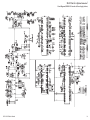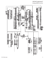
1
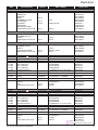
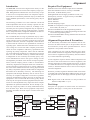
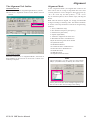
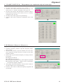
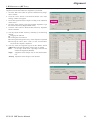
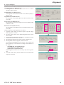
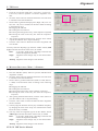
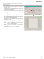
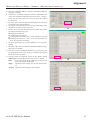
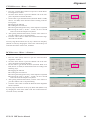
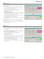
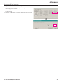
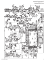
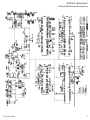
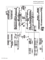
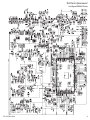
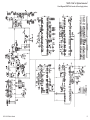
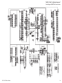
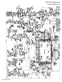
VHF Digital/Analog Transceiver Vertex Standard LMR, Inc. EVX-531 ©2013 Vertex Standard LMR, Inc. EC113N90F Service Manual Introduction This manual provides technical information necessary for servicing the EVX-531 VHF Hand-Held Digital/Analog Transceiver. Servicing this equipment requires expertise in handling surface-mount chip components. Attempts by non-qualified persons to service this equipment may result in permanent damage not covered by the warranty, and may be illegal in some countries. Two PCB layout diagrams are provided for each double-sided circuit board in the transceiver. Each side of is referred to by the type of the majority of components installed on that side (“leaded” or “chip-only”). In most cases one side has only chip components, and the other has either a mixture of both chip and leaded components (trimmers, coils, electrolytic capacitors, ICs, etc.), or leaded components only. While we believe the technical information in this manual to be correct, Vertex Standard assumes no liability for damage that may occur as a result of typographical or other errors that may be present. Your cooperation in pointing out any inconsistencies in the technical information would be appreciated. Important Note This transceiver is assembled using Pb (lead) free solder, based on the RoHS specification. Only lead-free solder (Alloy Composition: Sn-3.0Ag-0.5Cu) should be used for repairs performed on this apparatus. The solder stated above utilizes the alloy composition required for compliance with the lead-free specification, and any solder with the above alloy composition may be used. EVX-531 CAUTION Risk of explosion if battery is replaced by an incorrect type. Dispose of used batteries according to the instructions. Contents Specifications USA/EXP Models.......................................................................................................................................... 2 EU Model....................................................................................................................................................... 3 Exploded View & Miscellaneous Parts w/o Option Connector.................................................................................................................................... 4 w/ Option Connector...................................................................................................................................... 5 Parts List............................................................................................................................................................. 6 Block Diagram.................................................................................................................................................... 7 Circuit Description............................................................................................................................................ 8 Alignment......................................................................................................................................................... 10 MAIN Uuit (FR024510C) Circuit Diagram (w/o Option Connector)......................................................... 21 MAIN Uuit (FR024510E) Circuit Diagram (w/o Option Connector)......................................................... 24 MAIN-3 Uuit (FR025740A) Circuit Diagram (w/ Option Connector). ...................................................... 27 EVX-531 VHF Service Manual 1 Specifications (USA/EXP Models) General Frequency Range: Channel / Group: Emission Type: Power Supply Voltage: Current Consumption: Channel Separation: Operating Temperature Range: Frequency Stability: Antenna Impedance: Dimension (W x H x D): Weight (Approx.): 136-174 MHz 32 Channel / 2 Group 16K0F3E / 11K0F3E (Analog) 7K60F1E / 7K60FXE (Digital: 12.5 kHz Voice) 7K60F1D / 7K60FXD (Digital: 12.5 kHz Data) 7K60F1W (Digital: Combination of 12.5 kHz Voice & Data) 7.4 V DC ±10 % 1.8 A (5 W TX) 12.5 / 25 kHz (Analog) (USA Model: 12.5 kHz) 12.5 kHz (Digital) –22 °F to +140 °F (–30 °C to +60 °C) ±1.5 ppm 50 ohm (unbalanced) 2.3” x 4.4” x 1.2” (58.4 x 112.5 x 30.5 mm) w/FNB-V133LI-UNI 2.3” x 4.4” x 1.5” (58.4 x 112.5 x 38 mm) w/FNB-V134LI-UNI 9.4 oz (276 g) w/FNB-V133LI-UNI, Antenna, Belt Clip 11.1 oz (315 g) w/FNB-V134LI-UNI, Antenna, Belt Clip Receiver: Measured by TIA603/603D Circuit Type: IF Sensitivity: Conducted Spurious: Adjacent Channel Selectivity: Intermodulation: Spurious & Image Rejection: Hum and Noise: Audio output: Double Conversion Super-heterodyne 50.85 MHz / 101.7 MHz 0.25 µV (Analog, 12 dB SINAD) 0.28 µV (Digital 1 % BER) –57 dBm 70 dB (25 kHz Step, TIA-603) 60 dB (12.5 kHz Step, TIA-603) 70 dB (25 kHz Step, TIA-603D) 45 dB (12.5 kHz Step, TIA-603D) 65 dB (25 kHz Step) 60 dB (12.5 kHz Step) 70 dB –45 dB (25 kHz Step) –40 dB (12.5 kHz Step) 500 mW (internal @ 4 ohm 5% THD) 350 mW (external @ 4 ohm 5% THD) Transmitter: Measured by TIA603/603D Output Power: Modulation Type: Maximum Frequency Deviation: Conducted Spurious Emissions: FM Hum & Noise: Audio Distortion: 5.0 / 2.5 / 1.0 / 0.25 W Sigma Delta Modulation ±5.0 kHz (25 kHz Step, Analog) ±2.5 kHz (12.5 kHz Step, Analog) 1745 Hz - 2138 Hz (12.5 kHz Step, Symbol Deviation) 70 dB Below Carrier –45 dB (25 kHz Step) –40 dB (12.5 kHz Step) 3 % @1 kHz Specifications subject to change without notice or obligation. EVX-531 VHF Service Manual 2 Specifications (EU Model) General Frequency Range: Channel / Group: Emission Type: Power Supply Voltage: Current Consumption: Channel Separation: Operating Temperature Range: Frequency Stability: Antenna Impedance: Dimension (W x H x D): Weight (Approx.): 136-174 MHz 32 Channel / 2 Group 16K0F3E / 14K0F3E / 11K0F3E (Analog) 7K60F1E / 7K60FXE (Digital: 12.5 kHz Voice) 7K60F1D / 7K60FXD (Digital: 12.5 kHz Data) 7K60F1W (Digital: Combination of 12.5 kHz Voice & Data) 7.4 V DC ±10 % 1.8 A (5 W TX) 12.5 / 20 / 25 kHz (Analog) 12.5 kHz (Digital) –30 °C to +60 °C ±1.5 ppm 50 ohm (unbalanced) 58.4 x 112.5 x 30.5 mm w/FNB-V133LI-UNI 58.4 x 112.5 x 38 mm w/FNB-V134LI-UNI 276 g w/FNB-V133LI-UNI, Antenna, Belt Clip 315 g w/FNB-V134LI-UNI, Antenna, Belt Clip Receiver: Measured by ETS 300 086 Circuit Type: IF Sensitivity: Conducted Spurious: Adjacent Channel Selectivity: Intermodulation: Spurious & Image Rejection: Hum and Noise: Audio output: Double Conversion Super-heterodyne 50.85 MHz / 101.7 MHz 0.4 µV (Analog, 20 dB SINAD) 0.28 µV (Digital 1 % BER) –57 dBm @<= 1 GHz, –47 dBm @>1 GHz 70 dB (25 kHz Step) 60 dB (12.5 kHz Step) 65 dB 70 dB –45 dB (25 kHz Step) –40 dB (12.5 kHz Step) 500 mW (internal @ 4 ohm 5% THD) 350 mW (external @ 4 ohm 5% THD) Transmitter: Measured by ETS 300 086 Output Power: Modulation Type: Maximum Frequency Deviation: Conducted Spurious Emissions: FM Hum & Noise: Audio Distortion: 5.0 / 2.5 / 1.0 / 0.25 W Sigma Delta Modulation ±5.0 kHz (25 kHz Step, Analog) ±4.0 kHz (20 kHz Step, Analog) ±2.5 kHz (12.5 kHz Step, Analog) 1745 Hz - 2138 Hz (12.5 kHz Step, Symbol Deviation) –36 dBm @<= 1 GHz, –30 dBm @>1 GHz –45 dB (25 kHz Step) –40 dB (12.5 kHz Step) 3 % @1 kHz Specifications subject to change without notice or obligation. EVX-531 VHF Service Manual 3 Exploded View & Miscellaneous Parts (w/o Option Connector) Disconnect the Speaker Connector from the MAIN Unit when remove the Front Case of the transceiver. CB6343000 MIC/SP CAP ASSY CB6388000 FRONT CASE SUB ASSY CB6341000 FRONT CASE ASSY To Disconnecting the Speaker Connector: 1. Hook the lever. RA125090A (x 2 psc) BUSH RA125100A KNOB (VOL) 2. Pull up and friction lock is released. RA125110A KNOB (FREQ) RA066320A RUBBER PACKING (SP) RA1396900 WASHER M4090157 SPEAKER (36N-D2114B) T9207535A WIRE ASSY j 3. Positive lock is released and removal completes. j l l l l l l l l l To Connecting the Speaker Connector: 1. Insert the cable side first. RA1483000 SHIELD COVER (FET) RA1483100 SHEET (HEAT8X8t1) CB6340000 MAIN UNIT ASSY 2. Press down at the lever side. RA090590A (x 2 psc) NUT (C065) Note:Horizontal mating could damage the connector. FRONT CASE ASSY (Component) FRONT CASE MODEL LABEL NAME PLATE ESCUTCHEON (16CH) DOUBLE FACE TAPE (ECS) PLATE (FREQ) RUBBER (TOP SEL) SUPPORT (TOP SEL) LIGHT GUIDE SP NET RUBBER (PTT) FRAME (PTT) SHEET (PTT) RUBBER (SIDE) LATCH NAIL LATCH PLATE COIL SPRING (2.2x12x0.25) (2 pcs) SPONGE RUBBER (LED) SHEET (M-TEX 9x4.5) O RING (3.0x0.9) PAN HEAD SCREW (M2X3BSUS#2) BIND HEAD TAPTITE-B (M2X5) (2 pcs) FRONT CASE SUB ASSY (Component) KNOB (VOL) KNOB (FREQ) WASHER BUSH (2 pcs) CAP (MIC/SP) SPEAKER WIRE ASSY SPEAKER HOLDER (2 pcs) RUBBER PACKING (SP) O RING (CAP) O RING (0.8x2.2) (2 pcs) BINDING HEAD SCREW (M2.6X6B) (2 pcs) RA037690B SHEET (6x6) RA1496800 SHEET (GM10) RA1458000 RUBBER BOOTS RA1448500 RUBBER PACKING (CHASSIS) CB6342000 CHASSIS ASSY k k Li-Ion BATTERY PACK FNB-V133LI-UNI (AAJ67X001) or FNB-V134LI-UNI (AAJ68X001) CHASSIS ASSY (Component) CHASSIS CONNECTOR (SMAP-BT4WP) RUBBER PACKING (CHASSIS) RUBBER BOOTS SHEET (6x6) BIND HEAD TAPTITE-B (2X10) (2 pcs) MAIN UNIT (Component) Printed Circuit Board with Components HOLDER RUBBER (MIC) SHIELD COVER (FET) SHEET (HEAT8X8t1) NUT (C065) (2 pcs) PAN HEAD TAPTITE-B (M2X5) (9 pcs) BELT CLIP CLIP-20 (AAH12X101) REF. j k l VXSTD P/N DESCRIPTION QTY. U24105001 BIND HEAD TAPTITE-B M2X5 2 U24110001 BIND HEAD TAPTITE-B 2X10 2 U44105001 PAN HEAD TAPTITE-B M2X5 9 DESCRIPTION Battery Pack FNB-V133LI-UNI Desktop Charger CD-58 AC Adapter PA-55C or PA-55U Belt Clip CLIP-20 VXSTD P/N AAJ67X001 AAJ72X001 PA-55C: AAJ71X003 PA-55U: AAJ71X004 AAH12X101 Non-designated parts are available only as part of a designated assembly. EVX-531 VHF Service Manual 4 Exploded View & Miscellaneous Parts (w/ Option Connector) Disconnect the Speaker Connector from the MAIN Unit when remove the Front Case of the transceiver. To Disconnecting the Speaker Connector: 1. Hook the lever. CB6343000 MIC/SP CAP ASSY CB6341000 FRONT CASE ASSY CB6388000 FRONT CASE SUB ASSY RA125090A (x 2 psc) BUSH RA125100A KNOB (VOL) 2. Pull up and friction lock is released. RA125110A KNOB (FREQ) RA066320A RUBBER PACKING (SP) RA1396900 WASHER M4090157 SPEAKER (36N-D2114B) T9207535A WIRE ASSY k k 3. Positive lock is released and removal completes. m m m m m m m m m RA1483000 SHIELD COVER (FET) RA1483100 SHEET (HEAT8X8t1) To Connecting the Speaker Connector: 1. Insert the cable side first. CB6615000 MAIN-3 UNIT ASSY 2. Press down at the lever side. RA090590A (x 2 psc) NUT (C065) RA037690B SHEET (6x6) RA1496800 SHEET (GM10) Note:Horizontal mating could damage the connector. FRONT CASE ASSY (Component) FRONT CASE MODEL LABEL NAME PLATE ESCUTCHEON (16CH) DOUBLE FACE TAPE (ECS) PLATE (FREQ) RUBBER (TOP SEL) SUPPORT (TOP SEL) LIGHT GUIDE SP NET RUBBER (PTT) FRAME (PTT) SHEET (PTT) RUBBER (SIDE) LATCH NAIL LATCH PLATE COIL SPRING (2.2x12x0.25) (2 pcs) SPONGE RUBBER (LED) SHEET (M-TEX 9x4.5) O RING (3.0x0.9) PAN HEAD SCREW (M2X3BSUS#2) BIND HEAD TAPTITE-B (M2X5) (2 pcs) FRONT CASE SUB ASSY (Component) KNOB (VOL) KNOB (FREQ) WASHER BUSH (2 pcs) CAP (MIC/SP) SPEAKER WIRE ASSY SPEAKER HOLDER (2 pcs) RUBBER PACKING (SP) O RING (CAP) O RING (0.8x2.2) (2 pcs) BINDING HEAD SCREW (M2.6X6B) (2 pcs) RA1458000 RUBBER BOOTS RA1448500 RUBBER PACKING (CHASSIS) l CB6342000 CHASSIS ASSY l j j Li-Ion BATTERY PACK FNB-V133LI-UNI (AAJ67X001) or FNB-V134LI-UNI (AAJ68X001) BELT CLIP CLIP-20 (AAH12X101) CHASSIS ASSY (Component) CHASSIS CONNECTOR (SMAP-BT4WP) RUBBER PACKING (CHASSIS) RUBBER BOOTS SHEET (6x6) LID (OPTION) PACKING PAD (OPTION) SHEET (MICROTEX C010) PAN HEAD SCREW (M2X2.5(3KA)) (2 pcs) BIND HEAD TAPTITE-B (2X10) (2 pcs) MAIN-3 UNIT (Component) Printed Circuit Board with Components HOLDER RUBBER (MIC) SHIELD COVER (FET) SHEET (HEAT8X8t1) NUT (C065) (2 pcs) PAN HEAD TAPTITE-B (M2X5) (9 pcs) REF. j k l m VXSTD P/N DESCRIPTION QTY. U07225001 PAN HEAD SCREW M2X2.5 (3KA) 2 U24105001 BIND HEAD TAPTITE-B M2X5 2 U24110001 BIND HEAD TAPTITE-B 2X10 2 U44105001 PAN HEAD TAPTITE-B M2X5 9 DESCRIPTION Battery Pack FNB-V133LI-UNI Desktop Charger CD-58 AC Adapter PA-55C or PA-55U Belt Clip CLIP-20 VXSTD P/N AAJ67X001 AAJ72X001 PA-55C: AAJ71X003 PA-55U: AAJ71X004 AAH12X101 Non-designated parts are available only as part of a designated assembly. EVX-531 VHF Service Manual 5 Parts List MFR’s DESIG (SP) 36N-D2114B M2X5 VXSTD P/N CB6341000 CB6388000 RA125100A RA125110A RA1396900 RA125090A RA066320A RA1458300 M4090157 T9207535A CB6343000 U24105001 CHASSIS ASSY (AC113N001) RUBBER PACKING RUBBER BOOTS SHEET BIND HEAD TAPTITE-B 2 pcs (CHASSIS) (6x6) 2X10 CB6613000 RA1448500 RA1458000 RA037690B U24110001 CHASSIS ASSY (AC113N003) RUBBER PACKING RUBBER BOOTS SHEET PAN HEAD SCREW 2 pcs BIND HEAD TAPTITE-B 2 pcs (CHASSIS) (6x6) M2X2.5 (3KA) 2X10 CB6614000 RA1448500 RA1458000 RA037690B U07225001 U24110001 F 1001 MC1001 Q 1513 S 1001 S 1002 S 1003 S 1004 S 1006 TH1001 VR1001 X 1001 X 1501 XF1501 MAIN UNIT (w/o Option Connector) CHIP FUSE 3.15A, 36V MIC. ELEMENT FET TACT SWITCH TACT SWITCH TACT SWITCH TACT SWITCH ROTARY SWITCH THERMISTOR POT. XTAL 32.768kHz TCXO 19.2MHz XTAL FILTER SHIELD COVER SHEET NUT 2 psc PAN HEAD TAPTITE-B 9 pcs FHC16 322ADTP PF0-1055P RQA0011DNS EVQPUB02K EVQP8403M EVQPUB02K EVQPUB02K TP7NBPC16 14.7F RY-10115 TH05 4B473FR TP76N975N13.5FB503RY10034 4809995L18 32.768KHZ TTS27NSC-A7 19.2MHZ DSF753SDF 50.85MHZ (FET) (HEAT8X8t1) (C065) M2X5 CB6340000 Q0000118 M3290045 G3070392 N5090167 N5090173 N5090167 N5090167 N0190198 G9090150 J60800314 H0103407 H9501380 H1102479 RA1483000 RA1483100 RA090590A U44105001 F 3001 MC3001 Q 3513 S 3001 S 3002 S 3003 S 3004 S 3006 TH3001 VR3001 X 3001 X 3501 XF3501 MAIN-3 UNIT (w/ Option Connector) CHIP FUSE 3.15A, 36V MIC. ELEMENT FET TACT SWITCH TACT SWITCH TACT SWITCH TACT SWITCH ROTARY SWITCH THERMISTOR POT. XTAL 32.768kHz TCXO 19.2MHz XTAL FILTER SHIELD COVER SHEET NUT 2 psc PAN HEAD TAPTITE-B 9 pcs FHC16 322ADTP PF0-1055P RQA0011DNS EVQPUB02K EVQP8403M EVQPUB02K EVQPUB02K TP7NBPC16 14.7F RY-10115 TH05 4B473FR TP76N975N13.5FB503RY10034 4809995L18 32.768KHZ TTS27NSC-A7 19.2MHZ DSF753SDF 50.85MHZ (FET) (HEAT8X8t1) (C065) M2X5 CB6615000 Q0000118 M3290045 G3070392 N5090167 N5090173 N5090167 N5090167 N0190198 G9090150 J60800314 H0103407 H9501380 H1102479 RA1483000 RA1483100 RA090590A U44105001 REF. DESCRIPTION FRONT CASE ASSY FRONT CASE SUB ASSY KNOB (VOL) KNOB (CH) WASHER BUSH RUBBER PACKING SP HOLDER SPEAKER WIRE ASSY MIC/SP CAP ASSY BIND HEAD TAPTITE-B VALUE 2 pcs 2 pcs 4-ohm 2 pcs When replace a chip fuse, use the part of the same type and value. EVX-531 VHF Service Manual 6 Block Diagram EVX-531 VHF Service Manual 7 Circuit Description 1. Receiver System 1-1. Front-end RF amplifier Incoming RF signal from the antenna passes through the Low-pass filter, antenna switching diode Dx513, Dx514 (both 1SS390), and the RF attenuator Qx508 (SKY12338), and then removed undesired frequencies by the varactor tuned bandpass filter Dx515 and Dx516 (both 1SV325). The filtered RF signal is amplified by Qx518 (2SC5006) and then passes through another varactor tuned band-pass filter Dx520 and Dx521 (both 1SV325) to remove the undesired frequencies, and then applied to the 1st mixer Qx523 (3SK293). 1-2. First Mixer The RF signal is mixed with the 1st local signal between 186.85 and 224.85 MHz in the 1st mixer Qx523 (3SK293), to produce 50.85 MHz 1st IF signal. The 1st local signal is generated by the VCO, which consists of Qx506 (2SC5006), varactor diodes Dx502 (1SV279), Dx504 (xSV282), Dx507 (1SV279), and Dx508 (1SV282). The 1st local signal is supplied to the 1st mixer Qx523 (3SK293) through the buffer amplifier Qx510 (2SC5005) and amplifier Qx524 (2SC5006). 1-3. IF Amplifier & Demodulator The 1st IF signal is applied to the monolithic crystal filter XFx501 to strip away all but the desired signal, and then supplied to the custom IC Qx522 (RODINIA) through the buffer amplifier Qx526 (2SC5226). The custom IC Qx522 (RODINIA) converts the 1st IF signal into the Base Band signal. The Base Band signal from the custom IC Qx522 (RODINIA) is applied to another custom IC Qx306 (OMAP), which is demodulated by the Digital Signal Processor. 1-4. Audio Amplifier The demodulated signal from the custom IC Qx306 (OMAP) is applied to another custom IC Qx017 (CPCAP). The custom IC Qx017 (CPCAP) adjusts the audio volume level, and then amplifies the audio signal up to 500 mW. The output signal from the custom IC Qx017 (CPCAP) is applied to the audio speaker. 2. Transmitter System 2-1. MIC Amplifier & Modulator The speech signal from internal microphone MCx001 or external microphone Jx003 is supplied to the custom IC Qx017 (CPCAP), which is amplified the speech signal. The amplified speech signal from the custom IC Qx017 (CPCAP) is supplied to another custom IC Qx306 (OMAP), which process the speech signal by the Digital Signal Processor. The processed speech signal from the custom IC Qx306 (OMAP) is supplied to the modulator section of the custom IC Qx522 (RODINIA), which modulates the speech signal into the FM or digital signal. 2-2. Drive & Final Amplifier Stages The modulated signal from the custom IC Qx522 (RODINIA) is buffered by Qx520 (2SK3077) and amplified by the driver amplifier Qx519 (RQA0004PXDQS), and then is applied to the final amplifier Qx513 (RQA0011DNS), which is amplified up to 5 watts output power. The transmit signal then passes through the antenna switch Dx512 (RN124S) and is low pass filtered to suppress away harmonic spurious radiation before delivery to the antenna. 2-3. Automatic Transmit Power Control The current detector Qx528-1 (AD8566ARM) detects the current of the final amplifier Qx513 (RQA0011DNS) and the driver amplifier Qx519 (RQA0004PXDQS), and converts the current difference to the voltage difference. The output from the current detector Qx528-1 (AD8566ARM) is compared with the reference voltage and amplified by the power control amplifier Qx528-2 (AD8566ARM). The output from the power control amplifier Qx528-2 (AD8566ARM) controls the gate bias of the driver amplifier Qx519 (RQA0004PXDQS) and the final amplifier Qx513 (RQA0011DNS). The reference voltage changes into four values (Transmit Power High and Low) controlled by custom IC Qx522 (RODINIA). Parts reference number is as follows MAIN Unit (w/o Option Connector): 1000 - 1999 MAIN-3 Unit (w/ Option Connector): 3000 - 3999 EVX-531 VHF Service Manual 8 Circuit Description 3. PLL Frequency Synthesizer 3-2. VCV (Varactor Control Voltage) Control The output frequency from TCXO is 19.2 MHz and the tolerance is ±1.5 ppm in the temperature range –22 °F to +140 °F (–30 °C to +60 °C). The tuning voltage (VCV) of the VCO establishes the lock range of VCO by controlling the cathode of varactor diode (Dx502 (1SV279), Dx504 (1SV282), Dx507 (1SV279), Dx508 (1SV282) for receiving, and Dx501 (1SV279), Dx503 (1SV282), Dx505 (1SV279), Dx506 (1SV282) for transmitting) from the custom IC Qx522 (RODINIA). 3-1. VCO (Voltage Controlled Oscillator) 3-3. PLL The frequency synthesizer consists of VCO, TCXO (Xx501), and the custom IC Qx522 (RODINIA). While the radio is receiving, the RX oscillator Qx506 (2SC5006) generates a programmed frequency between 186.85 and 224.85 MHz as 1st local signal. While the radio is transmitting, the TX oscillator Qx505 (2SC5006) generates a frequency between 136.00 and 174.00 MHz. The output from oscillator is amplified by buffer amplifier Qx510 (2SC5006) and then is divided, one is fed back to the PLL Circuit in the custom IC Qx522 (RODINIA). The other one is supplied to the 1st mixer Qx523 (3SK293) through the buffer amplifier Qx524 (2SC5005) in case of the reception. In the transmission, the output is modulated to the FM (or digital) in the custom IC Qx522 (RODINIA), and then supplied to the transmitter section described previously. EVX-531 VHF Service Manual The main constitution product of the PLL is equipped all with in the custom IC Qx522 (RODINIA), so that all processing regarding the frequency control is performed in the custom IC Qx522 (RODINIA). Parts reference number is as follows MAIN Unit (w/o Option Connector): 1000 - 1999 MAIN-3 Unit (w/ Option Connector): 3000 - 3999 9 Alignment Introduction Required Test Equipment The EVX-531 series has been aligned at the factory for the specified performance across the entire frequency range specified. Realignment should therefore not be necessary except in the event of a component failure. All component replacement and service should be performed only by an authorized Vertex Standard representative, or the warranty policy may be voided. r Radio Tester with calibrated output level at 500 MHz r In-line Wattmeter with 5% accuracy at 500 MHz r 50-ohm, 10-W RF Dummy Load r Regulated DC Power Supply (standard 7.5 VDC, 3 A) r Frequency Counter: ±0.2 ppm accuracy at 500 MHz r AF Signal Generator r AC Voltmeter r DC Voltmeter r VHF Sampling Coupler r IBM PC/Compatible Computer with Microsoft ® Windows® 2000, XP, Vista, or 7 Vertex Standard CE142 PC Programming Software r r Vertex Standard FIF-12 USB Programming Interface and CT-106 PC Programming Cable r Vertex Standard FRB-6 Tuning Interface Box and CT-160 Connection Cable The following procedures cover the sometimes critical and tedious adjustments that are not normally required once the transceiver has left the factory. However, if damage occurs and some parts are replaced, realignment may be required. If a sudden problem occurs during normal operation, it is likely due to component failure; realignment should not be done until after the faulty component has been replaced. We recommend that servicing be performed only by authorized Vertex Standard service technicians who are experienced with the circuitry and fully equipped for repair and alignment. Therefore, if a fault is suspected, contact the dealer from whom the transceiver was purchased for instructions regarding repair. Authorized Vertex Standard service technicians realign all circuits and make complete performance checks to ensure compliance with factory specifications after replacing any faulty components. Those who do undertake any of the following alignments are cautioned to proceed at their own risk. Problems caused by unauthorized attempts at realignment are not covered by the warranty policy. Also, Vertex Standard must reserve the right to change circuits and alignment procedures in the interest of improved performance, without notifying owners. Under no circumstances should any alignment be attempted unless the normal function and operation of the transceiver are clearly understood, the cause of the malfunction has been clearly pinpointed and any faulty components replaced, and the need for realignment determined to be absolutely necessary. The following test equipment (and thorough familiarity with its correct use) is necessary for complete realignment. Correction of problems caused by misalignment resulting from use of improper test equipment is not covered under the warranty policy. While most steps do not require all of the equipment listed, the interactions of some adjustments may require that more complex adjustments be performed afterwards. Do not attempt to perform only a single step unless it is clearly isolated electrically from all other steps. Have all test equipment ready before beginning, and follow all of the steps in a section in the order presented. 50-ohm Dummy Load Alignment Preparation & Precautions A 50- RF Dummy Load and in-line wattmeter must be connected to the main antenna jack in all procedures that call for transmission, except where specified otherwise. Correct alignment is not possible with an antenna. After completing one step, read the following step to determine whether the same test equipment will be required. If not, remove the test equipment (except dummy load and wattmeter, if connected) before proceeding. Correct alignment requires that the ambient temperature be the same as that of the transceiver and test equipment, and that this temperature be held constant between 20 °C and 30 °C. When the transceiver is brought into the shop from hot or cold air, it should be allowed time to come to room temperature before alignment. Whenever possible, alignments should be made with oscillator shields and circuit boards firmly affixed in place. Also, the test equipment must be thoroughly warmed up before beginning. Note:Signal levels in dB referred to in this procedure are based on 0 dBµ EMF = 1.0 µV. Test Setup Setup the test equipment as shown below for transceiver alignment, then apply 7.5 V DC power to the transceiver. SP/LOAD Switch: LOAD LOAD Switch: 16 RF Signal Generator SINAD Meter CT-160 SP OUT B Inline Wattmeter Sampling Coupler Deviation Meter ANT MIC/SP AF Signal Transceiver FRB-6 D-Sub 15-pin MIC IN Generator Connector Battery Terminal CLONE Port CT-104A, CT-106, or CT-171 Power Supply 7.5 VDC FIF-12 Computer (CE142) Frequency Counter EVX-531 VHF Service Manual 10 Alignment The Alignment Tool Outline Alignment Mode Installation the tool r Install the CE142 PC Programming Software to your PC. r Execute the “Alignment” function in the “Radio” menu of CE142. In the “Alignment Mode”, the aligned data written in the radio will be able to re-align its alignment data. The value of each parameter can be changed to desired position by “ ”/“ ” arrow key for data up/down, “ ”/“ ” arrow key for channel up/down, direct number input, and drag the mouse. Note: when all items are aligned, it is strongly recommended to align according to following order. The detail information is written in the help document of CE142 PC Programming Software. ê Action of the switches When the transceiver is in “Alignment Mode”, the action of PTT and KEY is ignored. All of the action is remote controlled by Computer. 1. VCO (confirmation only) 2. PLL Reference Frequency (Frequency) 3. RX Sensitivity (RX Tune) 4. Squelch (SQL/RSSI) 5. TX Power <High/Low3/Low2/Low1> 6. Maximum Deviation <Wide/Narrow> Adjust the following items when needed. ¦ Symbol Deviation ¦ Modulation Balance ¦ CTCSS Deviation <Wide/Narrow> ¦ DCS Deviation <Wide/Narrow> ¦ DTMF Deviation ¦ MSK Deviation ¦ Sequential Tone Deviation Unit During alignment, you may select the value among dBµV, µV (EMF or PD), or dBm by the “UNIT” box. When perform the RX Tune and SQL alignment, the RF level shows this unit according to this setting. EVX-531 VHF Service Manual 11 Alignment 1.VCO (RX VCO/TX VCO) - This parameter is for confirmation only and cannot align This parameter is to confirm whether the VCO status shall be “Lock” or “Unlock”. 1. Click the “VCO” button to open the “VCO” window. 2. Click the “CH” button on the desired channel. The RX VCO status (“Lock” or “Unlock”) will appear in the “RX” box. 3. Click the “PTT” button. The radio starts to transmit on the selected channel, and the TX VCO status (“Lock” or “Unlock”) will appear in the “TX” box. 4. Click the “PTT” button again to stop transmitting. 5. Click the “OK” button to finish the confirmation of the VCO status. ê 2.PLL Reference Frequency (Frequency) This parameter is to align the reference frequency for PLL. 1. Click the “Frequency” button to open the “Frequency Alignment” window. 2. Click the “PTT” button or press the “SPACE” bar of the computer’s keyboard, the radio will start to transmit on the center frequency channel. 3. Set the value to get the desired frequency according to the following ways: lDragging the slide bar lClicking the arrow buttons lPressing the left/right arrow key of the computer’s keyboard lEntering the value (“0000” - “FFFF”) in the “Current Data” box from the computer’s keyboard 4. After getting the desired frequency, click the “PTT” button or press the “SPACE” bar to stop transmitting. 5. Click the “OK” button to finish the frequency alignment and save the data. EVX-531 VHF Service Manual ê 12 Alignment 3. RX Sensitivity (RX Tune) This parameter is to align the RX BPF (Band Pass Filter) for Receive (RX) sensitivity. The PLL Reference Frequency (Frequency) alignment must be done before this alignment is performed. 1. Click the “RX Tune” button to open the “RX Sensitivity Alignment” window. 2. Click the “Auto” button on the desired channel. The “Auto Tuning” window will appear. 3. Set the RF Signal Generator output according to the indication of the screen. 4. Click the “Start” button to start the automatic alignment to get the best RX sensitivity (Highest RSSI value). 5. Click the “OK” button to finish the RX Sensitivity alignment and save the data. 1) You may adjust the RX sensitivity manually by the following method: lDragging the slide bar lClicking the arrow buttons lPressing the left/right arrow key of the computer’s keyboard lEntering the value (“800”- “FFF”) in the “Current Data” box from the computer’s keyboard 2) You may select the alignment type from the “Radio” button (ADJ Type) located at the bottom of the screen, as needed. Basic: “Low-edge / band center / high-edge” and select the channel for alignment (Default). Single: Alignment value changes only on the selected channel. All Freq: Alignment value changes on all channels. ê ê EVX-531 VHF Service Manual 13 Alignment 4.Squelch (SQL) This parameter is to align the SQL (Squelch) Sensitivity. There are several alignment items as follows in the Squelch Sensitivity. Threshold SQL Level (Wide/Narrow) The alignment for the Noise SQL Threshold level at Wide (5k/4k) or Narrow (2.5k). Normal RSSI Level (Wide/Narrow) The alignment for the RSSI Normal level at Wide (5k/4k) or Narrow (2.5k). Tight RSSI Level (Wide/Narrow) The alignment for the RSSI Tight level at Wide (5k/4k) or Narrow (2.5k). SQL Close Level (Wide/Narrow) The alignment for the Noise SQL Close level at Wide (5k/4k) or Narrow (2.5k). ê RSSI Close Level (Wide/Narrow) The alignment for the RSSI Close level at Wide (5k/4k) or Narrow (2.5k). The procedure for all the alignments is as follows. 1. Click the “Start” button you wish to align to open the “SQL/ RSSI Alignment” window. 2. Click the “Start” button on the desired alignment item to open other window. 3. Set the RF Signal Generator according to the indication of the window, then click the “Start” button. 4. The automatic alignment will start to get the optimum level. 5. The alignment result will appear in the “New” box. On the following alignment items, click the “Next” button and then repeat step 2-5 several times according to the indication of the window. Threshold SQL Level (Wide/Narrow) Normal RSSI Level (Wide/Narrow) Tight RSSI Level (Wide/Narrow) Other alignment items has not extra step; only one step procedure. 6. Click the “OK” button, then the data will be saved and the alignment is finished. EVX-531 VHF Service Manual ê ê ê 14 Alignment 5.TX Power This parameter is to align the “High Power”, “Low3 Power”, “Low2 Power”, or “Low1 Power” for the selected channel. 1. Click the “TX Power (High Pwr / Low3 Pwr / Low2 Pwr / Low1 Pwr)” button to open the “TX Power Alignment” window. 2. Click the “PTT” button on the desired channel. The radio starts to transmit on the selected channel. 3. Set the value to get desired output power (High: 5 W, Low3: 2.5 W, Low2: 1 W, Low1: 250 mW) on the Power Meter according to the following ways: lDragging the slide bar lClicking the arrow buttons lPressing the left/right arrow key of the computer’s keyboard lEntering the value in the entry box from the computer’s keyboard 4. After getting the desired output power, click the “PTT” button or press the “SPACE” bar to stop transmitting. 5. Click the “OK” button to finish the TX Power alignment and save the data. ê You may select the adjusting type from the “Radio” button (ADJ Type) located at the bottom of the screen, as needed. Basic: “Low-edge / band center / high-edge” and select the channel for alignment (Default). Single: Alignment value changes only on the selected channel. All Freq: Alignment value changes on all channels. 6.Maximum Deviation <Wide> / <Narrow> This parameter is to align the “Maximum Deviation” (Wide/Narrow). 1. Press the “Max Dev (W/N)” button to open the “Max Deviation Alignment” window. 2. Click the “PTT” button on the desired channel. The radio starts to transmit on the selected channel. 3. Set the value to get desired deviation (Wide: 4.2 kHz, Narrow: 2.1 kHz) on the deviation meter according to the following ways: lDragging the slide bar lClicking the arrow buttons lPressing the up-down key of the computer’s keyboard lEntering the value in the entry box from the computer’s keyboard 4. After getting the desired deviation, click the “PTT” button or press the “SPACE” bar to stop transmitting. 5. Click the “OK” button to finish the Max Deviation alignment and save the data. ê 1) You may align the deviation level by any modulation frequency by changing the value of the “Freq” box located at the bottom left of the screen, if needed. 2) You may select the alignment type from the “Radio” button (ADJ Type) located at the bottom of the screen, as needed. Basic: “Low-edge / band center / high-edge” and select the channel for alignment (Default). Single: Alignment value changes only on the selected channel. All Freq: Alignment value changes on all channels. EVX-531 VHF Service Manual 15 Alignment Perform the following alignments as needed. Symbol Deviation This parameter is to align the deviation of the digital mode artificially. 1. Press the “Symbol Dev” button to open the “Symbol Deviation Alignment” window. 2. Click the “PTT” button on the desired channel. The radio starts to transmit on the selected channel. 3. Set the value to get Target Deviation (which is indicated on the screen) on the deviation meter according to the following ways: lDragging the slide bar lClicking the arrow buttons lPressing the up-down key of the computer’s keyboard lEntering the value in the entry box from the computer’s keyboard 4. After getting the desired deviation, click the “PTT” button or press the “SPACE” bar to stop transmitting. 5. Click the “OK” button to finish the Symbol Deviation alignment and save the data. ê You may select the alignment type from the “Radio” button (ADJ Type) located at the bottom of the screen, as needed. Basic: “Low-edge / band center / high-edge” and select the channel for alignment (Default). Single: Alignment value changes only on the selected channel. All Freq: Alignment value changes on all channels. EVX-531 VHF Service Manual 16 Alignment Modulation Balance <Wide> / <Narrow> (This Alignment is difficult.) This parameter is to align the “Modulation Balance” (Wide/Narrow). 1. Press the “Mod Bal” button to open the “Modulation Balance Alignment” window. 2. Confirm the modulation frequency which is indicated in the “Freq” box located at the bottom left of the screen is “50 (Hz)”. If not, enter the value (50) in the “Freq” box from the computer’s keyboard. 3. Click the “PTT” button on the desired channel. The radio starts to transmit on the selected channel. 4. Write down a deviation level, then enter the “4000 (Hz)” of the modulation frequency to the “Freq” box. 5. Set the value to get the same deviation level that wrote down according to the following ways: lDragging the slide bar lClicking the arrow buttons lPressing the left/right arrow key of the computer’s keyboard lEntering the value (“0” - “3FF”) in the “Current Data” box from the computer’s keyboard 6. Click the “PTT” button or press the “SPACE” bar to stop transmitting. 7. Click the “OK” button to finish the Modulation Balance alignment and save the data. 1) You may align the modulation balance by any frequency pair by changing the value of the “Freq” box located at the bottom left of the screen, if needed. 2) You may select the alignment type from the “Radio” button (ADJ Type) located at the bottom of the screen, as needed. Basic: “Low-edge / band center / high-edge” and select the channel for alignment (Default). Single: Alignment value changes only on the selected channel. All Freq: Alignment value changes on all channels. EVX-531 VHF Service Manual ê ê 17 Alignment CTCSS Deviation <Wide> / <Narrow> This parameter is to align CTCSS Deviation of the selected channel. 1. Press the “CTCSS (W/N)” button to open the “CTCSS Deviation Alignment” window. 2. Click the “PTT” button or press the “SPACE” bar of the computer’s keyboard to transmit the radio. 3. Set the value to get desired deviation (Nominal: Wide: 0.6 kHz, Narrow: 0.35 kHz) on the deviation meter according to the following ways: lDragging the slide bar lClicking the arrow buttons lPressing the left/right arrow key of the computer’s keyboard lEntering the value (“–20.00” - “20.00”) in the “Currend Data” box from the computer’s keyboard 4. After getting the desired deviation, click the “PTT” button or press the “SPACE” bar to stop transmitting. 5. Click the “OK” button to finish the CTCSS Deviation alignment and save the data. ê You may align the deviation level by any CTCSS tone frequency (default: 67.0 Hz) by changing the value of the “CTCSS Freq” box located at the bottom of the screen, if needed. DCS Deviation <Wide> / <Narrow> This parameter is to align “DCS Deviation” of the selected channel. 1. Press the “DCS (W/N)” button to open the “DCS Deviation Alignment” window. 2. Click the “PTT” button or press the “SPACE” bar of the computer’s keyboard to transmit the radio. 3. Set the value to get desired deviation (Nominal: Wide: 0.65 kHz, Narrow: 0.4 kHz) on the deviation meter according to the following ways: lDragging the slide bar lClicking the arrow buttons lPressing the left/right arrow key of the computer’s keyboard lEntering the value (“–20.00” - “20.00”) in the “Currend Data” box from the computer’s keyboard 4. After getting the desired deviation, click the “PTT” button or press the “SPACE” bar to stop transmitting. 5. Click the “OK” button to finish the DCS Deviation alignment and save the data. ê You may align the deviation level by any DCS code (default: 532) by changing the value of the “DCS Code” box located at the bottom of the screen, if needed. EVX-531 VHF Service Manual 18 Alignment DTMF Deviation This parameter is to align “DTMF Deviation”. 1. Press the “DTMF” button to open the “DTMF Deviation Alignment” window. 2. Click the “PTT” button or press the “SPACE” bar of the computer’s keyboard to transmit the radio. 3. Set the value to get desired deviation (Nominal: 3.0 kHz) on the deviation meter according to the following ways: lDragging the slide bar lClicking the arrow buttons lPressing the left/right arrow key of the computer’s keyboard lEntering the value (“–20.00” - “20.00”) in the “Currend Data” box from the computer’s keyboard 4. After getting the desired deviation, click the “PTT” button or press the “SPACE” bar to stop transmitting. 5. Click the “OK” button to finish the DTMF Deviation alignment and save the data. ê You may align the deviation level by any DTMF tone (default: “A”, available selection: “0” - “9”, “A” - “D”, “E(*)”, and “F(#)”) by changing the value of the “DTMF Code” box located at the bottom of the screen, if needed. MSK Deviation This parameter is to align “MSK Deviation” which use for the ANI operation of the MDC1200 System. 1. Press the “MSK” button to open the “MSK Deviation Alignment” window. 2. Click the “PTT” button or press the “SPACE” bar of the computer’s keyboard to transmit the radio. 3. Set the value to get desired deviation (Nominal: 3.0 kHz) on the deviation meter according to the following ways: lDragging the slide bar lClicking the arrow buttons lPressing the left/right arrow key of the computer’s keyboard lEntering the value (“–20.00” - “20.00”) in the “Currend Data” box from the computer’s keyboard 4. After getting the desired deviation, click the “PTT” button or press the “SPACE” bar to stop transmitting. 5. Click the “OK” button to finish the MSK Deviation alignment and save the data. EVX-531 VHF Service Manual ê 19 Alignment Sequential Tone Deviation This parameter is to fine-tune of the “Sequential Tone Deviation” for the 2-Tone and 5-Tone Encoder. 1. Press the “Seq Tone” button to open the “Sequential Tone Deviation Alignment” window. 2. Entering the desired value in the “New” box from the computer’s keyboard. 3. Click the “OK” button to finish the Sequential Tone Deviation alignment and save the data. ê EVX-531 VHF Service Manual 20 MAIN Unit (w/o Option Connector) Circuit Diagram (FR024510C: Interface & Power Supply Sections) EVX-531 VHF Service Manual 21 MAIN Unit (w/o Option Connector) Circuit Diagram (FR024510C: Control Section) EVX-531 VHF Service Manual 22 MAIN Unit (w/o Option Connector) Circuit Diagram (FR024510C: RF Section) EVX-531 VHF Service Manual 23 MAIN Unit (w/o Option Connector) Circuit Diagram (FR024510E: Interface & Power Supply Sections) EVX-531 VHF Service Manual 24 MAIN Unit (w/o Option Connector) Circuit Diagram (FR024510E: Control Section) EVX-531 VHF Service Manual 25 MAIN Unit (w/o Option Connector) Circuit Diagram (FR024510E: RF Section) EVX-531 VHF Service Manual 26 MAIN-3 Unit (w/ Option Connector) Circuit Diagram (FR025740A: Interface & Power Supply Sections) EVX-531 VHF Service Manual 27 MAIN-3 Unit (w/ Option Connector) Circuit Diagram (FR025740A: Control Section) EVX-531 VHF Service Manual 28 MAIN-3 Unit (w/ Option Connector) Circuit Diagram (FR025740A: RF Section) EVX-531 VHF Service Manual 29 Copyright 2013 Vertex Standard LMR, Inc. All rights reserved. No portion of this manual may be reproduced without the permission of Vertex Standard LMR, Inc. EVX-531 VHF Service Manual 21