1
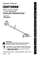
Operator's
_
P
R
0
F
E
Manual
S
S
I
0
N
A
L_
28cc/1.7 cu.in. 2-Cycle
GASOLINE
WEEDWACKER
®
Model No.
358.791980
•
Safety
•
•
•
Assembly
Operation
Maintenance
•
Parts List
•
Espa_ol,
&
p. 19
WARNING:
Read and follow all Safety Rules and Operating
Instructions before first use of this product.
For answers
Call 7 am-7
to your questions about this product:
pro, Mon.-Sat.,
or 10 am-7 pro, Sun.
1-800-235-5878
Sears, Roebuck
545167661
(Hours
listed
are
Centr_
31me)
and Co., Hoffman
Rev. 3
6/19/08
BRW
Estates,
IL 60179 U.S.A.
Warranty
Storage
13
Identification of Safety Symbols
Safety Rules
Assembly
Operation
Maintenance
Statement
2
4
6
7
10
Troubleshooting Table
Emissions Statement
14
15
Parts List
Spanish
17
19
Service & Adjus_nents
11
Parts and Ordering
CRAFTSMAN
PROFESSIONAL
2
Sack Cover
FULL WARRANTY
When used and maintained according to the operator's manual, if this product fails
due to a defect in material or workmanship within three (3) years from the date of
purchase, retum it to any Sears store, Sears Service Center, or other Craftsman outlet in the United States for flee repair (or replacement if repair proves impossible).
This warranty applies for only 1 year from purchase date if this product is ever
used for commercial or rental purposes.
This warranty covers ONLY defects in material and workmanship.
Sears will
NOT pay for:
• Expendable items that can wear out from normal use within the warranty period,
such as cutting line, filters or spark plugs=
• Repairs necessary because of accident or failure to operate or maintain the
product according to all supplied instructions.
• Preventive maintenance, or repairs necessary due to improper fuel mixture,
contaminated or stale fuel.
This warranty gives you specific legal rights, and you may also have other tights
which vary from state to state.
Sears, Roebuck and Co=, Hoffman Estates, IL 60179
®®®
_DANGER:
Use only specified trimmer
head, spool, and recommended trimmer line.
Never use blades, flailing devices, wire,
rope, string, eto. This unit is designed for line
trimmer use only. Failure to follow these
instructions may result in serious injury.
improper use can cause serious injury.
]_WARNING:
This unit can be dangerous! Careless
I_
_1
or
instructions could result in serious injury. Save operator's
manual.
Read the operator's manual before use. Failure to follow
Trimmer
linecanthrow
objects
violently.
Youcanbeblinded
orinjured.
Always wear hearing protection and
safety glasses marked Z87. Always
wear heavy, long pants, long
sleeves, boots and gloves.
Hazard zone for thrown objects.
• Trimmer line throws objects violently.
• You and others can be blinded/injured.
• Keep children, bystanders, and animals
50 feet (15 meters) away.
®®®
Secure hair above shoulder length.
Do not wear jewelry, loose clothing,
or clothing with loosing hanging
straps, ties, tassels, etc. They can
be caught in moving parts.
Assist handle to be positioned only below
the arrow.
Never allow children to operate this unit.
l
__
__
I
reach of children. Store unit and fuel in area where
fuel vapors cannot reach sparks or open flames
from water heaters, elecl_ic motors or switches,
i Store unit indoors in a high, dry place out of the
furnaces, etc.
ment parts.
When sen/icing unit, use only identical replace-
Always stop unit and disconnect spark plug before
cleaning or servicing.
_IWARNING:
Fire hazard. Never mix, pour, or store gasoline
or use the unit near a flame or sparks (including smoking, open
flames, or work that can cause sparks).
ltt+'
Use unleaded gasoline and two-stroke oil mixed at a
ratio of 40:1 (2.5%).
J
_ WARNING:
When using gardening appliances, basic safety precautions must always be followed to
reduce the nsk of fire and serious
injury. Read and fellow all instructions.
Th,_ power unit can be dangerous! Operator is responsible for following
instructions and warnings on unit and in
manual. Read entire operator's manual
before using unit! Be thoroughly familiar
with the consols and the proper use of
the unit. Rester the use of this unit to
persons who have read, understand,
and will follow the instructions and
warnings on the unit and in the manual.
Never allow children to operate this unit.
OPERATOR'S
MANUAL
SAFETY
INFORMATION
ONTHE UNIT
A
DANGER:
Never use blades or
flailing devices. This unit is designed
for line trimmer use only. Use of any
other accessories or attachments will
increase the risk of injury.
If situations occur which are not covered in this manual, use care and
good judgment. If you need assistance, contact your Sears Service
Center or call 1_00-235_._78.
OPERATOR SAFETY
• Dress properly. Always wear safety
glasses or similar eye protection
when operating, or performing maintenance, on your unit (safety
glasses are available). Eye protection should be marked Z87.
• Always wear face or dust mask if
operation is dusty.
• Always wear heavy, long pants, long
sleeves, boots, and gloves. Wearing
safety leg guards is recommended.
• Always wear foot protection. Do not
go barefoot or wear sandals. Stay
clear of spinning line.
• Secure hair above shoulder length.
Secure or remove loose clothing or
clothing with loosely hanging ties,
straps, tassels, etc. They can be
caught in moving parts.
• Being fully covered also helps protect you from debris and pieces of
toxic plants thrown by spinning line.
• Stay Alert. Do not operate this unit
when you are tired, ill, upset or under the influence of alcohol, drugs,
or medication. Watch what you are
doing; use common sense.
• Wear hearing protection.
• Never start or run inside a closed
room or building. Breathing exhaust
fumes can kill.
• Keep handles free of oil and fuel.
UNIT / MAINTENANCE
SAFETY
_WARNING:
Disconnect
the
spark plug before performing maintenance except carburetor adjustments.
• Look for and replace damaged or
loose parts before each use. Look
for and repair feel leaks before use.
Keep in good working condiiton.
• Replace t_mmer head parts thst are
chipped, cracked, broken, or damaged in any other way before using
the unit.
• Maintain unit according to recommended procedures. Keep cutting
line at proper length.
• Use only Craftsman@ replacement
line. Never use wire, rope, string, etc.
• install required shield properly before
using the unit. Use only specified trimmer head; make sure it is propedy
installed and securely fastened.
• Make sure unit is assembled correctly as shown in this manual.
• Make carburetor adjustments with
lower end supported to prevent line
from contacting any object.
• Keep others away when making carburetor adjustments.
• Use only recommended Craftsman
accessories and replacement parts.
• Have all maintenance and service
not explained in this manual performed by a Sears Service Center.
FUEL SAFETY
• Mix and pour fuel outdoors.
• Keep away from sparks or flames.
• Do not smoke or allow smoking near
fuel or the unit or while using the unit.
• Avoid spilling fuel or oil. Wipe up all
fuel spills before staring engine.
• Move at least 10 feet (3 meters)
away from fueling site before starting engine. Stop engine and allow it
to cool before removing fuel cap.
• Empty the fuel tank before storing or
ftanspordng the unit. Use up fuel left
in the carburetor by starting the engine and let_ng it run until it stops.
• Store unit and fuel in area where fuel
vapors cannot reach sparks or open
flames from water heaters, alectdc
motors or switches, furnaces, etc.
• Always store gasoline in a container
approved for flammable liquids.
CUTTING SAFETY
WARNING:
Inspect the area before each use. Remove objects
(rocks, broken glass, nails, wire, etc.)
which can be thrown by or become
entangled in line. Hard objects can
damage the trimmer head and be
thrown causing serious injury.
• Use only for tnmming, scalping, mowing, edging and sweeping. Do not use
for pruning or hedge trimming.
• Keep firm footing and balance. Do
not overreach.
• Keep all parts of your body away
from muffler and spinning line. Keep
engine below waist level. A hot motfieF can cause serious burns.
• Cut only from your right to your left.
Cutting on left side of the shield will
throw debris away from the operator.
• Use only in daylight or good artificial
light.
• Use only for jobs explained in this
manual.
TRANSPORTING
AND STORAGE
• Stop the unit before carrying.
• Allow engine to cool before storing
or transporting in vehicle.
• Empty the fuel tank before storing or
transporting the unit. Use up fuel left
in the carburetor by starting the engine and letting it run until it stops.
• Store unit and fuel in area where fuel
vapors cannot reach sparks or open
flames from water heaters, elec_aic
motors or switches, furnaces, etc.
• Store unit so line limitsr blade cannot accidentally cause injury. The
unit can be hung by the shaft.
• Store unit out of reach of children.
This unit is not equipped with an antivibration system and is intended for
occasional use only.
SAFETY NOTICE: Exposure to vibrations through prolonged use of gasoline powered hand tools could cause
blood vessel or nerve damage in the
fingers, hands, and joints of people
prone to circulation disorders or abnormal swellings. Prolonged use in
cold weather has been linked to blood
vessel damage in otherwise healthy
people. If symptoms occur such as
numbness, pain, loss of strength,
change in skin color or texture, or loss
of feeling in the fingers, hands, or
joints, discontinue the use of this tool
and seek medical attention. An antivibration system does not guarantee
the avoidance of these problems. Users who operate power tools on a continual and regular basis must monitor
closely their physical condition and the
condition of this tool.
SPECIAL NOTICE: This unit is
equipped with a temperature limiting
muffler and spark arresting screen
which meets the requirements of Califernia Codes 4442 and 4443. All U.S.
forest land and the states of California,
Idaho, Maine, Minnesota, New Jersey,
Oregon, and Washington require by
law that many internal combustion engines be equipped with a spark arresting screen. If you operate in a locale
where such regulations exist, you are
legally responsible for maintaining the
operating condition of these parts.
Failure to do so is a violation of the
law. For normal homeowner use, the
muffler and spark arresting screen will
not require any service. After 50 hours
of use, we recommend that your muffler be serviced or replaced by a
Sears Service Center.
CARTON CONTENTS
Check carton contents against the following list.
Model 358.791980
• Trimmer
• Shield
• Wing Nut (screwed onto shield)
• Container of line
• Container of oil
Examine parts for damage. Do not
use damaged parts.
NOTE: If you need assistance or find
parts missing or damaged, call
1-800-235-5878.
It is normal fur the fuel filter to rattle in
the empty fuel tank.
Finding fuel or oil residue on muffler is
normal due to carburetor adjustments
and testing done by the manufacturer.
A'I-rAC HING SHIELD
_'
WARNING:
Bracket
ASSEMBLY
_WARNING:
IfreceNed
as-
sembled,
repeat all steps to ensure
your unti is properly assembled and all
fasteners are secure.
ADJUSTING THE HANDLE
Shield
the safety label and below the mark or
arrow on the sha_.
f. Loosen wing nut on handle.
2. Rotate the handle on the shaR to an
upright position; retighten wing nut.
The shield must be
properly installed. The shield provides
par_al protection from the risk of thrown
objects to the operator and others and
is equipped with a line limiter blade
which cuts excess line to the proper
leng_. The line limiter blade (on underside of shield) is sharp and can cut you.
For proper orienta_on of shield, see
KNOW YOUR TRIMMER illustration in
OPERATION section.
1. Remove wing nut,Tom shield.
2. Insert bracket into slot as shown.
3. Pivot shield until bolt passes
through hole in bracket.
4. Securely tighten wing nut onto pelt_
_ng
Nut
KNOW
YOUR
TRIMMER
READ THIS OPERATOR'S MANUALAND SAFETY RULES BEFORE OPERATING YOUR
UNE Compare the illisbations with your unit to familiarize yourself with the location
of the various conbols and edjusbnents. Save this manual for future reference.
Assist Handle
Throttle
Shaft
Trimmer
Head
Throttle
Trigger
Shield
L_" Muffler
J
Starter
Handle
ON/STOP
Switch
Une Umiter
Blade
Choke
Lever
ON/STOP SWITCH
The ON/STOP switch is used to stop
engine. To stop the engine, push and
release the engine ON/STOP switch.
PRIMER BULB
The PRIMER BULB removes air from
the carburetor and fuel lines and fills
them with fuel. This allows you to start
the engine with fewer pulls on the
starter rope. Activate the primer bulb
by pressing it and allowing it to return
to its original form.
THRO'FrLE
LOCK-OUT
The THROTI]JE LOCK-OUT must be
pressed with the palm of your hand as
you grip the throttle handle before the
trigger can be used. This feature
prevents you from accidentally
squeezing the throttle trigger.
CHOKE
The CHOKE helps to supply fuel to the
engine to aid in cold stsr_ng. Activate
the choke by moving the choke liver to
the FULL CHOKE position. After the engine attempts to start, move the choke
lever to the HALF CHOKE position. Once
engine has started, move the choke lever to the OFF CHOKE position.
BEFORE
quality synthe_c 2_ycli air-cooled
engine oil We recommend Craftsman
brand synthe_c oil. Mix gasoline and oil
at a ra_o of 40:1. A 40:1 ratio is obtained by mixing 3.2 ounces of oil with 1
gallon of unleaded gasoline. Included
with this trimmer is a 3.2 ounce container of oil. Pour the entire contents of this
container into 1 gallon of gasoline to
achieve the proper fuel mixture. DO
NOT USE automotive oil or marine oil.
These oils will cause engine damage.
When mixing fuel, follow instructions
printed on container.
STARTING
WARNING:
ENGINE
Be sure to read
the fuel information in the safety rules
before you begin. If you do not understand the safety rules, do not attempt
to feel your unit. Call 1-800-235-5878.
FUELING ENGINE
_ WARNING:
Remove feel cap
slowly when refueling.
This engine is cedJfledto operate on
unleaded gasoline. Before operation,
gasoline must be mb<edwith a good
7
Once
oil is added
to gasoline, shake
container momentarily to assure that
the fuel is thoroughly mixed. Always
read and follow the safety rules relating to fuel before fueling your unit.
IMPORTANT
Alcohol blended fuels (called gasohol
or using ethanol or methanol) can attract moisture which leads to separation and formation of acids during storage. Acidic gas can damage the fuel
system of an engine while in storage.
To avoid engine problems, empty the
fuel system before storage for 30 days
or longer= Drain the gas tank, start the
engine and let it run until the fuel lines
and carburetor are empty. Use fresh
fuel next season. Never use engine or
carburetor cleaner products in the fuel
tank or permanent damage may occur. See the STORAGE section for
additional information.
Primer Bulb
3.
Lever
_
_hoke
4.
This unit has the Sim-pul_ starting
system. You do not have to pull the
starter rope handle sharply or briskly. Pull starter rope handle with a
controlled and steady moiton until
engine sounds as if it is trying to
start, but do not bull rope more
than 3 times.
5. As soon as engine sounds as if it is
_ying to start, move choke lever to
HALF CHOKE posi_on.
6. Pull starter rope unitl engine runs.
NOTE: If the engine doesn_ start
after 6 pulls (st the HALF CHOKE
position), move the choke liver to
the FULL CHOKE position. Pull the
starter rope 2 more times. Move the
choke lever to the HALFCHOKE
position and pull the starter rope unitl the engine runs, but no more than
6 pulls. If the engine still doesn't
start, it is probably flooded. Proceed
to STAR33NGA FLOODED ENGINE.
7. Once the engine starts, allow it to
run 10 seconds, then move the
choke lever to the OFF CHOKE
position. NOTE: If engine dies with
the choke lever in the OFF CHOKE
position, move the choke lever to
the FULL CHOKE position and pull
the rope until engine runs, but no
more than 6 pulls.
STARTING A WARM ENGINE
1. Move the choke lever to the HALF
HOW TO STOP YOUR UNIT
• Release the throttle trigger.
• Push and release the engine ON/
STOP switch. The switch will automatically return to the ON position.
Wait 5 seconds before attempting to
restart unit to allow switch to reset.
HOW TO START YOUR UNIT
z_
ItmWARNING:
Avoid any contact
with the muffler. A hot muffler can
cause serious bums.
Starting Position
STARTING
Move choke lever to FULL CHOKE
position.
A COLD ENGINE
NOTE: DO NOT squeeze the throttle
trigger until the engine has started and
runs.
1. Set unit on a fiat surface.
2. Slowly press the primer bulb 10
itmes.
2.
3.
8
CHOKE posi_on.
Pull starter rope with a controlled
and steady motion until engine
runs, but no more than 6 pulls.
Alliw engine to run 15 seconds,
then move the choke lever to OFF
CHOKE.
NOTE: If engine has not started, pull
starter rope 5 more pulls. If engine still
does not run, it is probably flooded.
STARTING A FLOODED ENGINE
Flooded engines can be started by
placing the choke lever in the OFF
CHOKE posi_on; then, pull the rope to
clear the engine of excess fuel. This
could require pulling the starter handle
many times depending on how badly
the unit is flooded.
If the unit still doesn't start, refer to
TROUBLESHOOTING TABLE or call
1-800-235-5878.
OPERATING INSTRUCTIONS
To maximize operating efficiency, do
not run the engine for longer than 1
minute at a time at full throffie.
OPERATING POSITION
ALWAYS USE:
Eye Protec_on
Always release the throttle trigger and
allow the engine to retum to idle
speed when not cutting.
HOW TO STOP YOUR UNIT
• Release the throttle trigger.
• Push and release the engine ON/
STOP switch.
CUTTING METHODS
_WARNING:
Use minimum
speed and do not crowd the line when
cutting around hard objects (rock,
gravel, fence posts, etc.), which can
damage the trimmer head, become
entangled in the line, or be thrown
causing a serious hazard.
• The tip of the line does the cutting.
You will achieve the best performance and minimum line wear by not
crowding the line into the cutting
area. The right and wrong ways are
shown below.
33pof line doesthe Line crowded into
work
Long
Pants
cutting.
Right
Cut from your leftto your right.
_k WARNING:
Always wear eye
protection and hearing protection. Never
lean over the _mmer head. Rocks or
debits can ricochet or be thrown into
eyes and face and cause blindness or
other serious injury.
When operating unit, stand as shown
and check for the following:
• Wear eye protection, hearing protection andheavy
clothing.
• Hold trigger handle with right hand
and assist handle with left hand.
• Hold unit so that engine is below
waist level.
• Cut only from your ]eft to your right to
ensure debits is thrown away from
you. Without bending over, keep line
near and paraJ]elto the ground and
not crowded into material being cut.
Do not run the engine at a higher speed
than necessary. The cutting line will cut
efficiently when the engine is run at less
than full throtfle. At lower speeds, there
is less engine noise and vibration.
Bres.
Wr
• The line will easily remove grass
and weeds (TOm around walls,
fences, trees and flower beds, but it
also can cut the tender bark of trees
or shrubs and scar fences.
• For trimming or scalping, use less
than full throttle to increase line life
and decrease head wear, especially:
• During light duty cut_ng.
• Near objects around which the line
can wrap such as small posts,
trees or fence wire.
TRIMMING - Hold the bottom of the
trimmer head about 3 inches (8 cm)
above the ground and at an angle. Allow only the tip of the line to make
contact with vegetation. Do not force
trimmer line into work area.
Trimming
(8 crn) above
ground
SCALPING - The scalping technique
removes unwanted vegetation down to
the ground. Hold the bottom of the _immer head about 3 inches (8 cm) above
the ground and at an angle. Allow the
rip of the line to s'_ike the ground
around f_ees, posts, monuments, etc.
This technique increases line wear.
Mowing
Scalping
SWEEPING - The fanning acrion of the
rotaring line can be used to blew away
loose debris from an area. Keep the line
parallel to and above the area surface
and swing the tool from side to side.
Sweeping
MOWING - Your trimmer is ideal for
mowing in places conventional lawn
mowers cannot reach. In the mowing
position, keep the line parallel to the
ground. Avoid pressing the head into
the ground as this can scalp the
ground and damage the tool.
MAINTENANCE
SCHEDULE
WARNING:
Disconnect the spark plug before performing maintenance
except for carburetor adjustments.
CARE & MAINTENANCE TASK
WHEN TO PERFORM
Before each use
Check for loose fasteners and parts
Check for damaged or worn parts
Before each use
inspect and clean unit and decals
Clean air filter
After each use
Every 5 hours of operation
inspect muffler and spark arresting screen
Every 50 hours of operation
Replace spark plug
Yearly
GENERALRECOMMENDATIONS
The warranty on this unit does not
cover items that have been subjected
to operator abuse or negligence. To
receive full value from the warranty,
the operator must maintain unit as
instructed in this manual. Various adjustments will need to be made periodically to propedy maintain your unit.
CHECK FOR LOOSE
FASTENERS AND PARTS
• Spark Plug Boot
• Air Filter
• Housing Screws
• Assist Handle Screw
• Debris Shield
CHECK FOR DAMAGED OR
WORN PARTS
Contact Sears Service Center for replacement of damaged or worn parts.
• ON/STOP Switch - Ensure ON/STOP
switch functions properly by pushing
and releasing the switch. Make sure
engine stops. Wait 5 seconds before attempting to restart unit to allow switch to reset. Restart engine
and continue.
• Fuel Tank - Discontinue use of unit
if fuel tank shows signs of damage
or leaks.
• Debris Shield - Discontinue use of
unit if debris shield is damaged.
10
INSPECTAND
CLEAN
uNrrANDDECALS
• Aftereach
use,inspect
complete
unitfor loose or damaged parts.
Clean the unit and decals using a
damp cloth with a mild detergent.
• Wipe off unit with a clean dry cloth.
CLEAN AIR FILTER
A dirty air filter decreases engine performance and increases fuel consumption and h_l
emissions. Always
clean after every 5 hours of operation.
1. Clean the cover and the area
around it to keep dirt from falling
into the carburetor chamber when
the cover is removed.
2. Remove parts as illustrated.
NOTE: To avoid creating a fire hazard
or producing harmful evaporative
emissions, do not clean filter in gasoline or other flammable solvent.
3. Wash the filter in soap and water.
4. Anow fifler to dry.
5. Replace parts.
__Air
Filter Air Filter
I_
INSPECT MUFFLER AND SPARK
ARRESTING
SCREEN
WARNING:
The muffler on this
product contains chemicals known to
the State of Califumia to cause cancer.
As your unit is used, carbon deposits
build up on the muffler and spark arresting screen.
For normal homeowner use, however,
the muffler and spark arresting screen
will not require any service. After 50
hours of use, we recommend that your
muffler be serviced or replaced by your
Sears Service Center.
REPLACE SPARK PLUG
Replace the spark plug each year to
ensure the engine starts easier and
runs better. Set spark plug gap at
0.025 inch. Ignition timing is fixed and
nonadjustable.
1. Twist, then pull oft spark plug boot.
2. Remove spark plug from cylinder
and discard.
3. Replace with Champion RCJ-hY
spark plug and tighten securely
with a 3/4 inch socket wrench.
4. Reinstall the spark plug boot.
Cover
LINE REPLACEMENT
• Always use Craftsman replacement
line.
Choose the line size best suited for
the job at hand. Red line (#71-85908)
is designed for cutting grass and small
weeds. The black colored line
(#71-85909)
is designed for cutting
larger weeds and light brush.
NOTE: Before inserting new line into
the holes in the cutting head, identify
the proper holes. Follow directions as
shown on the line glide plate.
1. Remove the old line and line glide
plate from the cutting head.
2. Clean entre surface ofcut_ng head.
3. Reinstall line glide plate (see illustration). Align arrow with:
(_)
when using medium (red) or
large (black) line
when using lines with diameter
(_) smaller than medium (red) line
(bption_d)
Line glide Arrow
Cutting head
11
NOTE: Line glide plsCce
must be reinstalled in cut_ng head before inserting
new line.
4.
Insert both eeds of your line
through the proper holes in the
side of the cutting head.
5.
Pull the line and make sure the line
is against the hub and extended full
through the positioning tunnels.
Lineagainst
6. Correctly installed line will be the
same length on both ends.
REPLACING THE TRIMMER HEAD
1. Align bole in the dust cup with the
hole in the side of the gearbox by
rotating the arbor shaft.
2. Insert a small screwdriver into
aligned holes. This will keep the
shaft _Tom turning while removing
and installing trimmer head.
CARBURETOR
_
WARNING:
Keep others away
when making idle speed adjustments.
The trimmer head will be spinning during most ofthis procedure. Wear your
protective equipment and observe all
safety precautions. After making adjustments, the trimmer head must not
move or spin at idle speed.
The carburetor has been carefully set
at the factory. Adjustments may be
necessary if you notice any of the following conditions:
• Engine will not idle when the throttle is
released.
• The trimmer head moves or spins at
idle.
Make adjustments with the unit supported so the cutting attachment is off
the ground and will not make contact
with any object. Hold the unit by hand
while running and making edjus_'nents.
Keep all parts of your body away from
the cut_ng attachment andmuffier.
Idle Speed Adjustment
Allow engine to idle. Adjust speed until
engine runs without trimmer head
moving or spinning (idle too fast) or
engine stalling (idle speed too slow).
• Turn idle speed screw clockwise to
increase engine speed if engine
stalls or dies.
• Turn idle speed screw counterclockwise to decrease engine speed if
trimmer head moves or spins at idle.
_
Idk_Speed
/ /
/
AI_ WARNING:
Screw_
3.
4.
5.
While holding the screwdriver in
position, remove trimmer head by
turning clockwise.
Thread replacement trimmer head
onto the shaft by turning counterclockwise. Only tigl-;ten hand l_ght!
Remove the screwdriver.
ADJUSTMENT
Screw
Air Filter
Cover
Recheck the idle
speed after each adjustment. The
trimmer head must not move or spin at
idle speed to avoid serious injury to
the operator or others.
If you require further assistance or are
unsure about performing this procedure, contact your Sears Service Center or call our customer assistance
help line at 1-800-235-5878.
12
4_WAHNING:
Perform the following steps after each use:
• Allow engine to cool before storing
or transporting.
• Store unit and fuel in a well ventilated area where fuel vapors cannot
reach sparks or open flames from
water heaters, electric motors or
switches, furnaces, etc.
• Store unit with all guards in place.
Position unit so that any sharp object cannot accidentally cause injury.
• Store unit and fuel well out of the
reach of children.
SEASONAL STORAGE
Prepare unit for storage at end of season or if it will not be used for 30 days
or more.
If your unit is to be stored for a period
of time:
• Clean the entire unit before lengthy
storage.
• Store in a clean dry area.
• Lightly oil extemal metal surfaces.
FUEL SYSTEM
Empty the fuel system before storage
for 30 days or longer. Drain the gas
tank, start the engine and let it run until the fuel lines and carburetor are
empty. Use fresh fuel next season.
Under FUELING ENGINE in the OPERATION section of this manual, see message labeled IMPORTANT regarding
the use of gasohol in your engine.
Fuel stabilizer is an acceptable alternative in minimizing the formation of
fuel gum deposits duitng storage. Add
stabilizer to the gasoline in the fuel
tank or fuel storage container. Follow
the mix instructions found on stabilizer
container. Run engine at least 3 minutes after adding stabilizer.
Craftsman 40:1,2-cycle engine oil (air
cooled) is already blended with fuel
stabilizer. If you do not use this Sears
oil, you can add a fuel stabilizer to
your fuel tank.
ENGINE
• Remove spark plug and pour 1 teaspoon of 40:1,2-cycle engine oil (air
cooled) through the spark plug
opening. Slowly pull the starter rope
8 to 10 times to distribute oil.
• Replace spark plug with new one of
recommended type and heat range.
• Clean air filter.
• Check entire unit for loose screws,
nuts, and bolts. Replace any damaged, broken, or worn parts.
• At the beginning of the next season,
use only fresh fuel having the proper
gasoline to oil ratio.
OTHER
• Do not store gasoline from one season to another.
• Replace your gasoline can if it starts
to rust.
13
TROUBLESHOOTING
TABLE
WARNING:
Always stop unit and disconnect spark plug before performing all of the recommended remedies below except remedies that require
unit to be operating.
TROUBLE
CAUSE
REMEDY
Enginewill not
start.
1. Engineflooded.
1. See "Starting a Flooded Engine"in
Operation Section.
2. Filltank with correct fuel mixture.
3. Install new spark plug.
4. Check for dirtyfuel filter;replace.
Check for kinked or splitfuel line;
repair or replace.
5. ContactSears Service (see back cover).
2. Fueltank empty.
3. Spark plugnot firing.
4. Fuel not reaching
carburetor.
5. Carburetor requires
adjustment.
Enginewill
not idle
properly.
1. Carburetor requires
adjustment.
2. Crankshaft seals worn.
3. Compressionlow.
1. See "Carburetor Adjustment"in
Service and AdjustmentsSection.
2. ContactSeam S_
(see back cover).
3. Contact Seam S_
(see back cover).
Enginewill not
accelerate,
lacks power,
or dies under
a load.
1. Air filter dirty.
2. Spark plugfouled.
1. Clean or replace air fitier.
2. Clean or replace plug
and regap.
3. ContactSears Service (see back cover).
Engine
smokes
excessively.
Engine runs
hot.
3. Carburetor requires
adjustment.
4. Carbon build-upon
muffler outlet screen.
5. Compressionlow.
4. ContactSears Service (see back cover).
5. ContactSears Sewloe (see back cover).
1. Fuel mixture incorrect.
1. Emptyfuel tankand refillwith
correct fuel mixture.
2. Clean or replace airfilter.
3. Co_
Sears Sennce(see back cover).
2. Air filter dirty.
3. Carburetor requires
adjustment.
1. Fuel mixture incorrect.
1. See "Fueling Engine"in Operation
section.
2. Replace with correct spark plug.
3. ContactSears Serv=ce(see back cover).
2. Spark plugincorrect.
3. Carburetor requires
adjustment.
4. Carbon build-upon
muffleroutlet screen.
4. Co_
14
Sears Sennce(see back cover).
YOUR WARRANTY RIGHTS AND OBLIGATIONS: The U.S. Environmental
Preteclion Agency/California Air Resources Board and Sears, Roebuck
and Co., U.SJ_., are pleased to explain
the emissions control system warranty
on your year 2007 and later small offread engine. In California, all small offread engines must be designed, built,
and equipped to meet the State's s_ingent anti-smog standards. Sears must
warrant the emission control system on
your small off-road engine for the perk
ods of time listed below provided there
has been no abuse, neglect, or improper maintenance of your small off-road
engine. Your emission control system
includes parts such as the carburetor,
the ignition system and the fuel tank
(Califomia only). Where a warrantable
condition exists, Sears will repair your
small off-read engine at no cost to you.
Expenses covered under warranty include diagnosis, parts and labor.
MANUFACTURER'S
WARRANTY
COVERAGE: If any emissions related
part on your engine (as listed under
missions Con_ol Warranty Parts List)
is defoc_ve or a defect in the materials
or workmanship of the engine causes
the failure of such an emission related
part, the part will be repaired or replaced by Sears. OWNER'S WARRANTY RESPONSIBILITIES:
As the
small off-read engine owner, you are
responsible for the performance of the
required maintenance listed in your operator's manual. Sears recommends
that you retain all receipts covering
maintenance on your small off-road engine, but Sears cannot deny warranty
solely for the lack of receipts or for your
failure to ensure the performance of all
scheduled maintenance. As the small
off-road engine owner, you should be
aware that Sears may deny you warranty coverage if your small off-road
engine or a part of it has failed due to
abuse, neglect, improper maintenance,
unappreved medifica_ons, or the use of
parts not made or approved by the original equipment manufacturer. You are
responsible for presen_ng your small
off-read engine to a Sears authorized
repair center as soon as a problem exists. Warranty repairs should be completed in a reasonable amount of _me,
not to exceed 30 days. If you have any
ques_ons regarding your warranty rights
and responsibilities, you should contact
your nearest authorized service center
or call Sears at 1400-469-4663.
WARRANTY COMMENCEMENT
DATE: The warcanty period begins on
the date the small off-read engine is
purchased. LENGTH OF COVERAGE:
This warranty shall be for a period of
two years from the ini_al date of purchase. WHAT IS COVERED: REPAIR
OR REPLACEMENT
OF PARTS. Repair or replacement of any warranted
part will be performed at no charge to
the owner at an approved Sears Service Center. If you have any questions
regarding your warranty rights and responsibili_es, you should contact your
nearest authorized service center or call
Sears at 1-800-469-4663.
WARRANTY PERIOD: Any warranted part which
is not scheduled for replacement as required maintenance, or which is scheduled only for regular inspec_on to the
effect of "repair or replace as necessary" shall be warranted for 2 years.
Any warranted part which is scheduled
for replacement as required maintenance shall be warranted for the period
of time up to the first scheduled replacement point for that pert. DIAGNOSIS:
The owner shall not be charged for
diagnostic labor which leads to the determination that a warranted part is defec_ve if the diagnostic work is performed at an appreved Sears Service
Center. CONSEQUENTIAL
DAMAGES: Sears may be liable for damages to other engine components
caused by the failure of a warranted
part s_l( under warranty. WHAT IS NOT
COVERED: All failures caused by
abuse, neglect, or improper maintenance are not covered. ADD-ON OR
MODIRED PARTS: The use of edd-on
or modified parts can be grounds for
disallowing a warranty claim. Sears is
not liable to cover failures of warranted
parts caused by the use of edd-on or
modified parts. HOW TO RLE A
CLAIM: If you have any questions regarding your warranty rights and responsibililJes, you should contact your
nearest authorized service center or call
Sears at 1-800-469-4663.
WHERE TO
GEr WARRANTY SERVICE: Warranty
services or repairs shall be provided at
all Sears Service Centers. Call
1-800-469-4663.
15
MAINTENANCE, REPLACEMENT
AND REPAIR OF EMISSION RELATED PARTS: Any Sears approved
replacement part used in the performance of any warranty maintenance or
repair on emission related parts will be
provided without charge to the owner if
the part is under warranty.
EMISSION CONTROL WARRANTY
PARTS UST: Carburetor, Ignition System: Spark Plug (covered up to maintenance schedule), IgnilJonModule, Muffler including catalyst, Fuel Tank
(Califomia only). MAINTENANCE
STATEMENT: The owner is responsible
for the performance of all required maintenance as defined in the operator's
manual.
The information on file productlabel indicateswhich standardyour engine is certified.
Example: (Year) EPA Phase I or Phase 2 and!orCALIFORNIA.
This engine is ce_fied to be emissions compliant for the following use:
[]
Moderate (50 hours)
[]
Intermediate (125 hours)
[]
Extended (300 hours)
16
REPAIR
PARTS
GAS
MODEL
SEARS
Ref.
1.
2.
3.
4.
5.
6.
7.
8.
9.
10.
11.
12.
13.
14.
15.
16.
17.
18.
19.
20.
21.
22.
23.
24.
25.
part
NO.
545125301
545066002
545024202
530016448
530016449
530016454
545072103
545045601
545071801
545030601
545074201
530015820
545081899
530059185
530016152
545007507
530071765
530052285
530015814
530015820
530015775
530016014
530016152
545150701
530096099
TRIMMER
Description
A_sy Cable Wire Hamess
Trigger
Housing Throttle (RH)
Screw
Screw
Ref.
26.
27.
28.
358.791980
Part
No.
71 85740
De.trip'on
71_5908
71 _5909
530096039
AssyCuSing Head
Tube Twisted Line
Red Line
Slack Line
Plate Glide
545167661
545144402
Operator Manual
Decal Shaft Warning
Spring Trigger
Lockout Throttle
Sl_ng
Lcckout
Housing Throttle
Ki[ Switch
Handle Assist
Bolt
KikDriveshalt
Clamp-Handle
Wingnat
Flexshaff
Ki_Shield
Assy
Limite_Line
Screw
BoOt
Screw
Screw
Wingnut
Bracket
Shield
Assy Gearbox
(LH)
(Incl. 18,19)
REPAIR
SEARS
GAS
PARTS
TRIMMER
MODEL
358.791980
5
I
51
R_.
Part N_
1.
2.
3.
4.
5.
6.
7.
8.
8.
10.
11.
12.
13.
14.
15.
16.
17.
18.
19.
20.
21.
530150253
530016101
545071701
530057844
530058709
545050402
530035596
545051898
530016400
545001001
952030201
545050403
530016475
545160301
545102303
530059800
530695646
545081897
545073101
530019293
545105107
22.
23.
24.
25.
26.
27.
28.
29.
30.
31.
32.
545065202
530016448
545029901
545043201
530016426
530016449
545102703
545029801
545029701
530016468
545102702
33.
34.
545071601
530059780
Description
Filter
NutCarb.
Screw
Air Box
Lever Choke
Bulb Purge
_Ot Carb. Gasket (Incl. 8,64)
Adaptor Carb.
KitGnsket
(foam)
Bolt
Cylinder
Plug Spark (RCJ_SY)
I_JtCranksha6 Seal
WasheFBtarter
Spring Sta_er Cup
Assy Starter Cap
Coupling Starter
AssyFuel
Filter
h3t Fuel Line
AssyCap
w/ret.(Incl. 20)
O ring
Fuel Cap
Assy Fuel Tank
(Incl. 17,18,19,20)
Shroud Rear
Screw
W=t Rope
Handle Bta_er
Screw
Screw
Starter Housing w/eyelet
W=tStailer Spring
W=tSta_ler Pulley
Screw
AssySta_er
Hsg.
( Ind. 24,25,28,29,30,31
)
Plate Wear
Isolator Tank
Re =.
35.
36.
37.
38.
39.
40.
41.
42.
43.
44.
45.
46.
47.
48.
49.
50.
51.
52.
53.
54.
55.
56.
57.
58.
59.
60.
61.
62.
63.
64.
65
66.
67.
68.
69.
18
part No.
530058982
530015241
530150440
530016449
545065401
545030501
545057501
545076701
530015897
545046702
530039227
530016456
530016463
530094189
530016469
530016470
530015768
530016456
545072903
530150039
545050405
530057852
530038242
545054601
545013401
545030001
530015162
530019283
545030301
545081898
530015897
545081850
545071901
545072201
545081898
Description
Bolt Muffler
Screw
Shield Heat
Screw
Guard Muffler
}13tSpark
(incl. 36)
Assy Muffler
Gasket Paper Metal
Screw
Module
Assy Leadwire
Screw
Washer
WasheFClutch.
Screw
Screw
Locknut
Screw
Assy Fan Housing
Assy Clutch Drum
}_t Clutch Assy.
Spacer
Flywheel
Crankcase
Bearing
Kit Crankshaft
Ret. Piston Pin
Ring Pistan
Kit Piston (Incl. 61,62)
Kit Gasket (adaptor seal)
Screw
_Ot Carb. (Ind. 4,6)
CoveFAir Box
Assy Knob
_Ot Gasket(incl.
6,8,12,20,42,64)