1
OWNER'S
MANUAL
MODEL
_O.
580.328391
120=240 VOLT/8000
WATT
DELUXE PORTABLE GENERATOR
HOURS:
o
Assembly
Mon.- Fri. 8 a.m. to 5 p.m
o
Operation
o
Customer
CAUTION:
Read and Follow
o
Service
all Safety Rules
o
Repair Parts
(CST)
Responsibilities
and Adjustment
and Instructions
Before Operating
This Equipment
SEARS,
ROEBUCK
P=t No_984239._vi_o==
3 (7/t6/96)
and
CO.,
Hoffman
Estates,
IL
60179
U.S.A.
SAFETY
A
_
RULES
CAUT ON: ALWAYS DISCONNECT SPARK PLUG WIRE AND PLACE WIRE WHERE IT CANNOT CON..
TACT SPARK PLUG, To PREVENT ACCIDENTAL STARTING WHEN SETTING UP, TRANSPORTING,
ADJUSTING OR MAKING REPAIRS TO YOUR GENERATOR.
A
iMPORTANT
THIS GENERATOR IS DESIGNED FOR OUTDOOR USE ONLY. USING THIS GENERATOR INSIDE ANY BUILDING OR
ENCLOSURE,
NCLUDING THE GENERATOR COMPARTMENT OF A RECREATIONAL VEHICLE (RV), IS DANGEROUS.
FIRE OR AN EXPLOSION MAY RESULT. NO USER PERFORMED MODIFICATIONS,
INCLUDING VENT NG OF EXHAUST
AND/OR COOLING VENTILATION, WILL ELIMINATE THE DANGER.
O
o
O
If this unit is used for backup power in the event of
a utility power failure, take the following steps: BEFORE CONNECTING THE GENERATOR TO AN
ELECTRICAL SYSTEM OPEN THE MAIN CIRCUIT BREAKER OR MAIN SWITCH SERVING
THE SYSTEM TO ISOLATE THE GENERATOR
SYSTEM FROM THE ELECTRIC UTILITY. FAILURE TO ISOLATE THE GENERATOR AND UTILITY SYSTEMS MAY RESULT IN DAMAGE TO
THE GENERATOR AND MAY ALSO RESULT IN
INJURY OR DEATH TO ELECTRIC UTILITY
WORKERS DUE TO BACKFEED OF ELECTRICAL ENERGY.
This generator supplies dangerously high electrical
voltages. Use care to prevent extremely hazardous
and possibly lethal electrical shock Never permit
any unqualified person(s) to operate or service the
unit.
DO NOT operate this equipment in the rain, while
standing in water, while barefoot, or while hands or
feet are wet Dangerous electrical shock will resulL
The spark arrestor muffler can become extremely
hot DO NOT operate this equipment in areas where
corrrbustible material such as grass, leaves or paper
products can come in contact with the muffier.
Maintain all wiring, extension cords, etc. in good
condition
Worn, bare, frayed, or otherwise damaged wiring and cord sets may cause dangerous
electrical shock and may also result in damage to
equipment and/or property,
The National Electrical Code requires that the gem
erator be properly connected to an approved earth
ground. Local electrical codes may also require
proper grounding of the unit. See ASSEMBLY section for more grounding information
Wire gauge sizes of wiring and cord sets must be
large enough to handle the maximum electrical load
to which they wilt be subjected. Most devices require cord sets rated 125 AC volts at 20 to 30
amperes or' 250 AC volts at 20 arnps (or greater).
Some devices may require a higher or lower rating
Refer to the Owner's manual of the electrical device
for the manufacturer's recommendations
Cord
sets that are too small in diameter or too long will
overfreat, become damaged and may cause property damage and/or electrical shock
e
The generator engine consumes oxygen and gives
off DEADLY carbon monoxide gas through its exhaust system. This dangerous gas, if breathed in
sufficient concentrations, can cause unconscioushess or even death_ Operate this equipment outdoors only, in well ventilated areas where exhaust
gases cannot accumulate and endanger people or
animals.
o
WARNING: Engine exhaust from this product contains chemicals known, in certain quantities, to
cause cancer, birth defects, or other reproductive
harm.
Gasoline is extremely FLAMMABLE and its vapors
are EXPLOSIVE. Comply with all laws regulating
the storage and handling of gasoline.. DO NOT
permit smoking, open flames, sparks or heat in the
vicinity while handling gasoline.
Avoid spilling
gasoline on a hot engine. DO NOT fill fuel tank
while engine is running or hot. Clean off any spilled
gasoline before starting engine.
DO NOT fill fuel tank completely full. Allow room at
top of tank for fuel expansion or fuel may expand
and overflow onto a hot engine
Drain all gasoline from tank before transporting your
generator inside your car or other vehicle.
DO NOT store the generator with fuel in tank where
gasoline vapors might reach an open flame, spark,
or pilot light, as on a furnace, water heater, dryer,
etc. FIRE or an EXPLOSION might resulL
DO NOT insert any object or tool through cooling air
slots or openings of the engine or generator, even
if the engine is not running Damage to the unit or
personal injury may resulL
DO NOT attempt to change the engine governed
speed_ Factory settings are correct when you receive the unit. Excessively high engine speeds may
result in injury or damage to equipment
DO NOT use the unit if it has been damaged. Repair
or replace all damaged or defective components
before you run the uniL
DO NOT permit children to operate or service the
generator.
Read your Owner's Manual carefully. Only persons
who are familiar with these safety rules and have
been properly instructed in the use of this product
should be permitted to use the product.
e
o
•
e
e
=
e
o
o
'1
MEANS
"ATTENTION!!!
ALERT!!!
YOUR SAFETY
IS INVOLVED."
LOOK FOR
THIS SYMBOL BECOME
TO POINT
OUT IMPORTANT
SAFETY
PRECAUTIONS.
iT
!
/
CONGRATULATIONS on your purchase of a Sears Craftsman Generator,
It has been designed, engineered and
manufactured to give you the best possible dependability
nd performance,
Should you experience any problem you cannot easily
remedy, please contact your nearest Sears Service Center/Department or call the 1_800 number listed on the front
of this manual, We have competent, well-trained technicians and the proper tools to service or repair this unit,
Please read and retain this manual. The instructions will
enable you to assemble and maintain your generator proper}y_ Always observe the 'SAFETY RULES_"
PRODUCT
SPECIFRCATRONS
Generator Specifications
RATED MAXIMUM
POWER
8000 Watts (8.0 kW)
RATED VOLTAGE
120/240 Volts a-o
RATED MAXIMUM
LOAD CURRENT
66.7/33.3 a-c amperes
RATED FREQUENCY
60 Hz at 3600 rpm
PHASE
Single Phase
TYPE OF BATTERY
MODEL
NUMBER
BATTERY CHARGE
580,328391
SERIAL
NUMBER
_
_
Series Y50-N 18L-A3
Amps:
Volts:
10 DC amps
12 volts DC
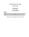
Engine Specifications
DATE OF
PURCHASE
THE MODEL AND SERIAL NUMBERS WILL BE
FOUND ON A DECAL ATTACHED TO THE GENERATOR STATOR CAN,
YOU SHOULD RECORD BOTH SERIAL NUMBER
AND DATE OF PURCHASE AND KEEP IN A SAFE
PLACE FOR FUTURE REFERENCE
MAINTENANCE
AGREEMENT
ENGINE MODEL
GN-Series
DISPLACEMENT
480cc
SPARK PLUG: Type:
Champion RC12YC or
or equivalent
0.030 inch (0.76mm)
Set Gap to:
MAXIMUM FULL TANK
OPERATING TIME (hrs)
full load
5
1/2
7
GASOLINE CAPACITY
5 U.S. gallons
OIL
SAE 30 Oil
(SAE 10W-30).
OIL CAPACITY
56 oz. with oil filter
46 oz, without filter
A Sears Maintenance Agreement is available on this product, Contact your nearest Sears store for details
CUSTOMER
RESPONSIBILIT ES
o
Read and observe the safety rules,
o
Follow regular schedule in maintaining, caring for and
using your generator
Follow the instructions under "Maintenance" and "Storage" sections of this Owner's Manual,
NOTE: This generator is equipped with a spark arrestor
muffler The spark arrestor must be maintained in effective
working order by the ownedoperator_
In the State of California a spark arrestor is required by law
(Section 4442 of the California Public Resources Code)
Other states may have similar laws, Federal laws apply on
federal lands,
TABLE OF CONTENTS
SAFETY RULES .....................ii.._o_........ L. INSIDE COVER
MAINTENANCE
AGREEMENT ........................................ 1
PRODUCT SPECIFICATIONS
CONTENTS
OF HARDWARE
.............................................1
............................................ 3
ASSEMBLY ...................................................................
SERVICE AND ADJUSTMENTS ...................................
SERVICE RECOMMENDATIONS ................................
13 (
14
STORAGE .....................................................................
14
TROUBLESHOOTING
POINTS ............................... __.. 15
WIRING DIAGRAM ............................................................. 16
4-5
OPERATION ........................................................................
6-10
REPAIR PARTS ............................................................ 17-25
MAINTENANCE
WARRANTY
................................................................
11-12
...................................................................
27
PARTS ORDERING .................................... BACK COVER
Undex
-R-
-H-
-AAir Cleaner ...........
Assembly ..............
6, 12
4-5
Head bolts ..................
11
Receptacles ..............
Retarque head bolts .......
4
11
-H-B-
Idle Control ...............
Before Starting .............
Battery Charging ..............
Battery Safety ............
7
9
8
-LLow Oil Shutdown ...........
Lubrication .................
-C-
9
7, 11
--Mm
Carburetor. ............
Circuit Breakers .........
Cord Sets ...................
Customer Responsibilites
Agreement ...................
13
4,6
4
1
-EEngine
Carburetor adjustment
Oil level ......................
8
Maintenance
Agreement
......................
Speed .........................
Electrical Loads ...........
13
11
11
11
11
Generator Maintenance
11
13
10
Oil Level ..................
Operation ...............
Overloading .................
........
Gasoline ....................
7
Grounding Lug ...........
4
Parts, repair .............
2
Specifications ...............
Starting Engine ..............
Stopping Engine ............
Storage .................
1
7
8
14
-TTroubleshooting
...........
15
Valve clearance, adjusting _. 13
11
66-10
10
-p-
-G-
Safety Rules ......
inside cover
Service and Adjustments...
13
Service Recommendations
. 14
1
Cleaning generator .........
Engine maintenance ............
General Recommendations .....
-O.........
-S-
17-24
Warranty .................
Wattage Reference Guide.
Widng Diagram ............
27
_ 10
16
CONTENTS OF HARDWARE PACK
Parts packed
separately,
in carton
' ...........
Parts Carton
t
Wheel Kit Bag
Main Unit
%Z
Handle
Wheels
Battery Installation
Parts Bag
Support Leg
Parts Packed in Parts Carton
Not Shown Full Size
(3) Twistlock Plugs
lHtllllll!lllli!
(4) Hex Head Capscrews
Part Packed in Parts Bag Not
Shown Full Size
Battery Bracket
Battery Charge Cable
Parts Packed
- M8 x 45mm
Owner's Manual
in Parts Bags
Shown
©
(7) Lock Nuts - M8
(2) Battery Connector Cables
Full Size
©
(2) Hex Nuts - 1/4"
(2) Hex Head Capscrews - M8 x 20mm
(2) Lock Washers - 1/4"
©
(1) Vibration Mount
Hex Head Capscrew - M8 x 30mm
©
(2) Fiat Washers - 1/4"
Washer - M8
(2) Retainer
Pins
(2) Washers - 5/8"
(2) Spacers
{2) 1/4"-20 x 7" Ho[ddown
Bolts
3
ASSEMBLY
Read these instructions and Operator's Manual in its entirety before you attempt to assemble or operate your new
AC generator.Your AC generator has, for the most part,
been assembled at the factory, except those parts left
unassembled Before you can operate your new AC generator, you must assemble the wheel kit and install a
battery, which you must purchase. It is ready for use after
it has been properly serviced with the recommended lubricating oil and fuel
13
IMPORTANT:
ANY ATTEMPT TO RUN THE ENGINE
BEFORE IT HAS BEEN SERVICED WITH THE RECOMMENDED OIL WILL RESULT IN AN ENGINE FAILURE.
IF YOU HAVE ANY PROBLEMS WITH THE ASSEMBLY
OF YOUR GENERATOR, PLEASE CALL THE GENERATOR HELPLINE AT 1-800-222-3136
TO REMOVE
o
o
,,
o
GENERATOR
FROM
CARTON
Cut down corners at one end of shipping carton and lay
that side of carton down flat
Remove packing material, carton fillers, etc.
Remove accessories box, carton and parts bags.
Remove generator' from shipping carton
4
FIGo I
iNSTALLiNG
You must purchase and install a 12 volts DC battery (6-cell,
Type Y50-NL18-A3). The battery should be properly serviced with electrolyte fluid and fully charged prior'to installation.
Refer to Page 3 "Contents of Hardware Pack" for an illustrated listing of all the items included with your generator
Become familiar with each piece before assembling the
generator. Check all contents against the illustrations on
Page 3 If any parts are missing or damaged, call the
Generator Helpline at 1-800-222-3136.
TOOLS
o
=
o
NEEDED
FOR
THE BATTERY
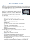
Install the battery as fotlows (Fig. 2):
=
ASSEMBLY
Retain battery to tray with bracket, (2) 1/4-20 x 7" bolts,
(2) 1/4" flat washers, (2) 1/4" lock washers and (2) 1/4"
lock nuts.
Two adjustable wrenches OR the following wrenches:
Two 1/4" combination wrenches
Two 1/2-inch (13mm) combination wrenches
iNSTALLiNG
WHEEL
KIT
The Sears Wheel kit was designed to greatly improve the
portability of the 8000 watt Sears Craftsman Deluxe Generator Install the Wheel Kit as follows:
=
o
Place the generator on a flat hard surface_
Slide axle (Item 3) through holes in the brackets provided on the generator cradle (Fig. 1) and then add the
two spacers (Item 5) on each protruding end of the axle
o- Stand at engine end of generator and gently tilt gener_
ator forward high enough to prop up front of the cradle
This will allow you to add the wheels.
= Slide on the wheels (Item 2) on each end of the axle
and retain each with 5/8" washer (item 10) and retain-.
ing pin (Item 4). Lower the generator
= Attach the vibration mount (Item 7) to the support leg
(Item 6) with M8 x 30rnm capscrew (Item 8), M8 washer
(Item 12) and M8 lock nut (Item 9) using the combination wrench_
o
o
BlackCable(-)
FIG. 2
°
With the wheels on, you can now tilt the generator end
forward and attach the support leg with two M8 x 20mm
capscrews (Item 11) and two lock nuts
Set the generator down so it is level and, using the
combination wrench, attach the handle with four M8 x
45mm capscrews and four lock nuts
•
4
Connect red battery cable from starter switch to battery
post or terminal indicated with POSITIVE, POS or (+)_
Tighten securely.
Connect black battery cable from engine mount bolt to
battery post or terminal indicated with NEGATIVE,
NEG or (-) Tighten securely.
ASSEMBLY
coRD
SETs
AND
CONNECTOR
PLUGS
120 VOLTS DUPLEX RECEPTACLE
Use only high quality, welt-insulated, extension cords with
the 120-volt "duplex" type electrical receptacles. All cord
sets used should be rated 125 volts at 20 AC amps or
greater for most electrical devices Keep extension cords
as short as possible, preferably less than 15 feet tong to
prevent voltage drop and wires from overheating.
120 VOLTS, 20 AND 30 AMP RECEPTACLES:
o
For the 120 volts, 20 amp locking type NEMA L5-20R
receptacle, a well-insulated cord set with a NEMA
L5-20P locking type connector plug must be properly
connected to the recept&cle and to the desired 120
volts, single phase, 60 Hz, AC load. Cord sets should
be rated 20 AC amperes at 125 volts (or greater) for
most electrical devices (Fig. 3).
_120
vOltS a.c_
FIG. 5
uniL For that purpose, a GROUNDING WING SCREW is
)rovided on the base of the cradle (Fig. 6).
FIG. 3
o
For 120 volts, 30 amp locking type NEMA L5-30R
receptacle, a welHnsulated cord set with a NEMA
L5-30P locking type connector plug must be properly
connected to the receptacle and the desired 120 volts,
single phase, 60 Hz, AC load The cord set should be
rated 30 AC amperes at 125 volts (or greater) for most
electrical devices (Fig. 3).
120/240 VOLTS, 30 AMP RECEPTACLE:
A 120/240 volts, 30 amp, locking type type mating connector plug (Fig 4) is required when using this receptacle A
4-wire cord set, rated 30 AC amperes at 250 volts (or
greater), is required and must be connected to the plug and
to the desired loads Order NEMA type L14-30P
240 VOLTS, 50 AMP RECEPTACLE
(Fig. 5)
This receptacle is rated 50 AC amperes at 250 volts. You
need a 3-prong grounded connector plug with same rating
to use with this outlet. Although current capacity of outlet
is rated at 50 amps, loads applied through this outlet should
not exceed 33.3 amps or you will overload the generator
GROUNDING
THE GENERATOR
The National Electrical Code requires that the frame and
external electrically conductive parts of this generator be
properly connected to an approved earth ground
Local
electrical codes may also require proper grounding of the
FIG. 6
Generally, connecting a No. 12 AWG (American Wire
Gauge) stranded copper wire to the grounding screw and
to an earth-driven copper or brass grounding rod (electrode) provides adequate protection against electrical
shock. However, local codes may vary widely. Consult with
a local electrician for grounding requirements in your are&
Proper grounding of generator will help prevent electrical
shock in the event of a ground fault condition in the generator or in connected electrical devices Proper grounding
also helps dissipate static electricity, which often builds up
in ungrounded devices
OPERATION
KNOW
YOUR
GENERATOR
READ THIS OWNER'S
MANUAL AND SAFETY RULES BEFORE OPERATING
YOUR GENERATOR.
Compare the
illustrations with your generator, to familiarize yourself with the locations of various controls and adjustments. Save this
manual for future reference_
AC CIRCUIT BREAKERS
ENGINE RUN/STOP SWITCH
IDLE CONTROL SWITCH
't2 VOLT, 10 AMP
BATTERY CHARGE
RECEPTACLE
120VOLTS"DUPLF.X"._
RECEPTACLES
I"_
120VOLTS, 20 AMP_ "/
RECEPTACLE
I
120 VOLTS, 30AMI
RECEPTACLE
120/240VOLTS,
RECEPTACLE
30 AMP
ENGINE RUN/STOP SWITCH -- Must be set to RUN to
start the engine_ Set switch to STOP to stop the engine.
120 VOLTS "DUPLEX" RECEPTACLES -- May be used
to supply electrical power for the operation of 120 volts at
20 amps AC, single phase, 60 Hz, AC electrical lighting,
appliance, tool and motor loads.
120 VOLTS, 30 AMP RECEPTACLE -- May be used to
supply electrical power for the operation of 120 volts at 30
amps AC, single phase, 60 Hz, AC electrical lighting,
appliance, tool and motor Ioads_ Locking type connectors
are required when using this receptacle
120 VOLTS, 20 AMP RECEPTACLE -- May be used to
supply electrical power for the operation of 120 volts at 20
amps AC, single phase, 60 Hz, AC electrical lighting,
appliance, tool and motor Ioads. Locking type connectors
are required when using this receptacle
2_.,OVOLTS, 5OA_P
RECEPTACLE
120/240 VOLTS, 30 AMP RECEPTACLE -- May be used
to supply electrical power for the operation of up to 240 volts
at 30 amps AC, single phase, 60 Hz, AC electrical lighting,
appliance, tool and motor Ioads. Locking type connectors
are required when using this receptacle.
AC CIRCUIT BREAKERS -- Protects the generator
against electrical overload
Breakers are "push to reset"
type for 15-amp, 20-amp and 30-amp loads.
SPARK ARRESTER MUFFLER -- Exhaust muffler has a
spark arrester screen_
240 VOLTS, 50 AMP RECEPTACLE -- May be used to
supply electrical power for the operation of up to 240 volts
at 50 amps AC, single phase, 60 Hz, AC electrical lighting,
appliance, tool and motor loads. Range connectors are
required when using this receptacle
FUEL LEVEL GAUGE - Indicates level of fuel in fuel tank.
12-VOLT D.C RECEPTACLE -- Recharge a discharged
12 volts automotive type battery through this outlet
(5
OPERATUON
BEFORE
STARTING
Crank engine,:
Electric Starting" Press start switch on generator
cradle until engine cranks. Keep pressing until it starts
(Fig, 10)
o
ENGINE
Add Oil:
,,
Place generator on a level surface and remove dipstick
from extended oil fill tube. Use SAE 30 detergent oil
classified "For Service SC, SD, SE, SF, SG." SAE
10W-30 oil may also be used, POUR SLOWLY, Oil
capacity of engine is about three (3) U.S. pints, When
oil is filled to dipstick FULL mark, install and tighten oil
fill plug.
RECOMMENDED SAE VISCOSITY GRADES
Manual Starting"
Grasp the starter grip and pull
slowly until you feel some resistance. Let rope return
slowly, then pull cord out with rapid full arm stroke. Let
rope return slowly° Do not let rope "snap back" against
starter, Repeat until engine starts_
o
o
I
¥ .2o
'c .30
.?
-20
When engine starts, move the choke to the open
position gradually as engine warms up_
Let the engine stabilize and warm up for a few minutes.
Check that the A_C. ON lamp on the generator panel is
ON before connecting any electrical loads.
I
._s 32.,,o . 50 . 80
-le
o
10
20
so
i0o
4o
TEMPERATURE
RANGEANTICIPATEDBEFORENEXTOIL CHANGE
"" Use synthetic
available,
5W-20, 5W-30or 5W-40 viscosity
If not
based oil may be used having 5W-20or 5W-30
oil having
a petroleum
viscosity
NOTE: 10W-40 oil may be used if 10W-30 is not available.
Add Gasoline:
_,
FIG. 7
IMPORTANT:
EXPERIENCE INDICATES THAT ALCOHOL-BLENDED FUELS (CALLED GASOHOL OR USING
ETHANOL OR METHANOL) CAN ATTRACT MOISTURE
WHICH LEADS TO SEPARATION AND FORMATION OF
ACIDS DURING STORAGE ACIDIC GAS CAN DAMAGE
THE FUEL SYSTEM OF AN ENGINE WHILE IN STORAGE TO AVOID ENGINE PROBLEMS WHEN USING
GASOHOL, THE FUEL SYSTEM SHOULD BE EMPTIED
BEFORE
STORAGE
PERIODS
OF 30 DAYS OR
LONGER. DRAIN THE GAS TANK, STARTTHE ENGINE
AND LET iT RUN UNTIL THE FUEL LINES AND CARBURETOR ARE EMPTY_ USE FRESH FUEL NEXT SEASON.
SEE STORAGE INSTRUCTIONS
FOR ADDITIONAL INFORMATION
NEVER USE ENGINE OR CARBURETOR CLEANER PRODUCTS IN THE FUEL TANK
OR PERMANENT DAMAGE MAY OCCUR
IGNITION
D
FIG. 9
CONNECTING
Unplug all electrical loads from generator receptacles before starting the engine Never start or stop the engine with
electrical devices plugged into panel receptacles and
turned on. Start, store and fuel the unit in a level position
,*
Open the fuel shutoff valve (Fig 7)
Apply the choke (Fig. 8). Pull choke lever to its FULL
CHOKE POSITION. If engine is warm, close the choke
only part way or leave it fully open A warm engine
needs less choking than a cold engine.
Set the Run/Stop Switch (Fig 9) to RUN position
F1G. 10
ELECTRICAL
LOADS
o
Use this generator to operate 120',240 volts, single
phase, 60 Hz, AC lighting, appliance, tool and motor
loads.
o
DO NOT connect 240 volts to the 120 volts duplex or
120 volts, 20 and 30-amp receptacles
DO NOT connect any 3-phase loads to panel receptacles
TO START THE ENGINE
o
,,
FIG. 8
Fill fuel tank with clean, fresh, UNLEADED gasoline
Leaded REGULAR grade gasoline may also be used
DO NOT USE PREMIUM GASOLINE BE CAREFUL
NOT TO OVERFILL FUEL TANK.
o
o
DO NOT connect any 50 Hz loads to the generator
Add up the rated watts of all lights, tool, appliance and
motor loads you are powering at one time. This total
should NOT be greater than (a) the generator's rated
wattage capacity, or (b) the circuit breaker rating of the
receptacle supplying power See "Don't Overload the
Generator" on Page 9
OPERATION
STOPPING
o
=
,,
o
A
THE ENGINE
Unplug all electrical loads from the generator panel
receptacles. Never start or stop the engine with elec..
trical devices plugged in and turned on_
Let engine run at no-load for several minutes to stabilize the internal temperatures of engine and generator
Set the Run/Stop Switch to STOP position. Wait for
engine to come to a complete stop (Fig. g).
Close the Fuel Shutoff Valve (Fig_ 7)_
OPERATING
AUTOMATgC
A
iDLE CONTROL
An Automatic Idle Control system provides greatly improved fuel economy and noise reduction by operating the
unit at its normal high governed speed only when electrical
loads are plugged in and turned ON, Tne system consists
of (a) Idle Control Cimuit Board, (b) Sensing Transformer,
(c) Stepper motor', and (d) Idle Control Switch located on
the control panel (Figure 11)
CAUTION: DO NOT permit _noklng, open flame,
sparks or any source of heat around a battery. DO
NOT use any lighter or other flame to provld_
lighting for checking battery fluid levels. Wear
protective goggles, rubber apron and rubber
gloves when working around a battery.
CAUSTIC SULFURIC ACID
CAUTION: Battery elestrolyte fluid is an extremely
caustic sulfuric acid solution that can cause severe
bums.
DO NOT permit fluid contact with eyes,
skin clothing, etc. if spillage occurs,flush with
clear water Immediately.
CHARGRNG
A BATTERY
Your generator has the capability of recharging a discharged, 12-volt automotive or utility style storage battery.
Do not use the unit to charge any 6-volt batteries_ Do not
use the unit to crank an engine having a discharged battery_
To recharge 12_volt batteries, proceed as follows:
=
"IDL._CONTROL
o
=
,,
Check fluid level in all battery cells. If necessary, add
ONLY distilled water to cover separators in battery
cells. DO NOT USE TAP WATER_
If the battery is equipped with vent caps, make sure
they are installed and are tighL
If necessary, clean battery posts or terminals_
Connect battery charge cable connector plug to panel
receptacle (Fig 12). identified by the words 12-VOLT
D.C."
FIG. 11
•
o
o
o
At start-up, the unit runs at either high or low governed
speed for several seconds (the speed it runs depends
on what the governed speed was when the unit was
last shut down). After several seconds, the unit automatically goes to an engine speed selected by the
position of the Idle Control Switch.
With the Idle Control Switch OFF, unit runs at high
governed speed (about 3600 RPM) whether loads are
connected or not.
With the Idle Control Switch ON, the unit immediately
goes to high governed speed when loads are applied.
When applying large loads, it is advisable to either
"bump" the load on for a short instant to allow the
engine speed to rise before applying the full load, or to
turn the Idle Control Switch OFF. When loads are
removed for more that several seconds, the unit auto °
matically goes to reduced (idle) speed.
The Idle Control Switch can be turned ON or OFF while
the unit is running, with loads connected or disconnected. When starting the unit, do not connect loads
for about 10 seconds to allow the engine speed to
stabilize_
BATTERY
A
I
12 VOLTS BATTER!
FIG. 12
o
=
o
SAFETY
o
EXPLOSIVE
HYDROGEN
GAS give off EXPLOSIVE
CAUTION: Storage
batteries
hydrogen gas while charging. An explosive mixture will remain around the battery for a long time
after it has been charged. The slightest spark can
ignite the gas and cause an explosion. Such an
explosion can shatter the battery and cause blindness or other serious injury.
Connect battery charge cable clampwith red handle to
battery post or terminal indicated by a POSITIVE, POS
or (+)
Connect battery charge cable clamp with black handle
to battery post or terminal indicated by a NEGATIVE,
NEG, or (--).
Start engine (see"Starting the Engine" on Page 5). Let
the engine run while battery recharges.
When battery has charged, shut down engine (see
"Stopping the Engine" on this page).
NOTE: Use an automotive hydrometer to test battery state
of charge and condition_ Follow the hydrometer manufacturer's instructions carefully. Generally, a battery is considered to be at 100% state of charge when specific gravity of
its fluid (as measured by hydrometer) is 1260.
8
OPERATUON
ENGINE
PROTECTIVE
LOW OIL PRESSURE
DEVgCES
SHUTDOWN
A Low Oil Pressure Shutdown switch (Fig. 13) on the
engine monitors tow oil pressure, The switch is normally
closed (N.C.), and is held open by engine oil pressure
during startup and operation Should engine oil pressure
drop below a safe value during operation, an automatic
shutdown occurs. This feature protects engine against
damaging low oil pressure conditions and engine failure.
If the engine shuts down unexpectedly,
level before attempting a restart..
check engine oil
CAUTIONh DO NOT A"n'EMPT TO OPERATE AN ]
ENGINE WITH LOW OIL PRESSURE BY UNPLUGGING LEAD FROM LOW OIL PRESSURE SWITCH
OR BY BYPASSING THE SWITCH IN ANY MAN-/
NER. OPERATING WITH LOW OIL PRESSURE
COULD DAMAGE ENGINE OR CAUSE FAILURE. J
RECEPTACLE
LOW OIL
FIG. 13
o
CIRCUIT BREAKERS
See DON'T OVERLOAD THE GENERATOR.
DON'T
OVERLOAD
THE GENERATOR
,,
This generator is equipped with three 20-amp and one
30-amp circuit breakers, which protect the unit against
electrical overload. Overloading a generator in excess of
its rated wattage capacity can result in damage to the
generator to connected electrical devices Observe the
following, to prevent overloading the unit:
o
Add up the total wattage of all electrical devices to be
connected at one time. This total should NOT be
greater than the generator's wattage capacity
WATTAGE
*Air Conditioner (12,000 Btu)
The GUIDE below is provided to assist you in determining how many items your generator can operate at
one time
REFERENCE
GUIDE
RUNNING
RUNNING
WATTS
WATTS
............................
Battery Charger (20 amp) ............................................
Belt Sander (3") .................................................
Chain Saw ..............................................................
Circular Saw (6-12/") ..................................
Coffee Maker .....................................................
o
The rated wattage of lights can be taken from light
bulbs. The rated wattage of tools, appliances and
motors can usually be found on a data plate or decal
affixed to the device, If the appliance, tool or motor does
not give wattage, multiply 120 volts times ampere rating
to determine watts (volts x amps = watts).
Some electric motors, such as induction types, require
about two and a half times more watts of power for
starting than for running. This surge of power lasts only
a few seconds when starting such motors. Make sure
you allow for this high starting wattage when selecting
electrical devices to connect to your generator. First,
figure the watts needed to start the largest motor. Add
to that figure the running watts of all other connected
loads.
1700
Lawn Mower ........................................................................1200
500
1000
1200
Light Bulb ........................................................................
100
Microwave Oven ....................................................................700
*Milk Cooler ....................................................................
1100
Oil Burner on Furnace
300
800 to 1000
1000
*Compressor (1 HP) .............................................
*Compressor (3/4 HP) ................................
Curling Iron ........................................................
2000
1800
700
*Deep Freeze ................................................
Disc Sander (9") .................................................
Electric Nail Gun ......................................
500
200
1200
Electric Range (one element) .............................
Electric Skillet ...........................................
1500
1250
*Furnace Fan (1/3 HP) ....................................
Hair Dryer ..............................................
Hand Drill (1") ........................................................
1200
1200
1100
Hedge Trimmer ...............................................................
450
....................................................
Oil Fired Space Heater (140,000 Btu) ...............................400
*Paint Sprayer, Airless (1/3 HP) ..................................... 600
Paint Sprayer, Airless (handheld) ................................... 150
Radio
50 to 200
....................................................................
*Refrigerator .............................................................
Slow Cooker ...........................................................
600
200
*Submersible Pump (1 HP) ......................................
2000
Sump Pump ...............................................................................
600
*Table Saw (10") ..........................................
Television .........................................................
Weed Trimmer
1750 to 2000
200 to 500
...........................................................
500
* Allow 2-1/2 times the listed watts for starting these devices,
CUSTOMER
GENERAL
RESPONS BULaTHES
CHANGING
RECOMMENDATIONS
Change oil after first 8 hours of operation. Change oil every
50 hours thereafter. If you are using your generator under
dirty or dusty conditions, or in extremely hot weather,
change oil more often,
The Owner/Operator is responsible for making sure that all
pedodic maintenance tasks are completed on a timely
basis; that all discrepancies are corrected; and that the unit
is kept clean and properly stored. Never operate a damaged or defective generator. Follow the recommendations
in the SERVICE RECOMMENDATIONS
chart on page 9.
A
I
Change oil while engine is still warm from running,
follows:
FROM SPARK PLUG AND PLACE WIRE WHERE IT |
CANNOT COME IN CONTACT WITH YOUR SPARK |
PLUG BEFORE
WORKING SPARK
ON YOUR
GENER-/
CAUTION:
DISCONNECT
PLUG
WIRE]
ATOR.
J
GENERATOR
OIL
I_
CAUTION:
Disconnect
sparkspark
plugplug.
wire from spark ]J
plug and keep
it away from
_,
Clean area around oil drain plug, remove plug (Fig. 14)
and drain oil completely into a suitable container.
MAINTENANCE
Generator maintenance constists of keeping the unit clean
and dry. Operate and store the unit in a clean dry environment where it will not be exposed to excessive dust, dirt,
moisture or any corrosive vapors Cooling air slots in the
generator must not become clogged with snow, leaves,or
any other foreign material.
OIL RLTER
'1
Check the cleanliness of the generator frequently and clean
when dust, dirt, oil, moisture or other foreign substances
are visible on its exterior surface
/j
NOTE: We DO NOT recommend using a garden hose to
clean generator_ Water can enter the engine fuel system
and cause problems In additon, if water enters the generator through cooling air slots, some of the water will be
retained in voids and cracks of the rotor and stator winding
insulation_ Water and dirt buildup on the generator'internal
windings will eventually decrease the insulation resistance
of these windings_
OIL DRAIN_
FIG. 14
°
When all oil has drained, install and tighten oil drain
plug.
o
Remove oil dipstick and insert a clean fill funnel into
extended oil fill opening
Fill engine crankcase to
dipstick FULL mark. Do not overfill above that mark.
About 3 pints is required. POUR SLOWLY.
o When engine crankcase is filled to proper level, install
and tighten oil fill plug.
REPLACE SPARK PLUGS
TO CLEAN THE GENERATOR:
o
,=
Use a damp cloth to wipe exterior surfaces clean_
A soft, bristle brush may be used to loosen caked on
dirt, oil, etc_
,,
A vacuum cleaner may be used to pick up loose dirt
and debris.
o
Low pressure air (not to exceed 25 psi) may be used
to blow away dirt. Inspect cooling air slots and openings on the generator_ These openings must be kept
clean and unobstructed.
Remove and replace spark plugs every 100 operating
hours or once annually, whichever comes firat. See ENGINE SPECIFICATIONS
on Page 1 for recommended
spark plugs_ Set gap (Fig 15) on spark plug to 0_030 inch
(0_76mm).
A_
CAUTION: Never insert any object or tool through
the air cooling slots, even if the engine Is not
running. Damage to the unit or personal injury may
result.
CAUTIONI DO NOT blast clean spark plugs. Clean ]
with pen knife or wire brush and solvent.
1
0 (]30" FEELER
ENGINE
as
MAINTENANCE
CHECKING OIL LEVEL
See OPERATION section on Page 7 for information on
checking oil level. Oil level should be checked prior to each
use or at least every eight hours of operation. Keep oil level
maintained
l
FIG. 15
10
GAUGE
CUSTOMER RESPONSitBIL TJES
CHANGE OIL FILTER
Change engine oil filter every 100 hours of operation (every
second oil change).
Before installing new filter, lightly
lubricate filter gasket with fresh, clean engine oil. Screw
new filter on by hand until gasket contacts the filter adapter
(Fig 16) Then tighten about 3/4 turn further Start and run
engine for about 30 seconds, then shut down. Recheck oil
level and add oil as necessary. Finally, start engine and
check for leaks,
=
o
Squeeze (don't twist) pre-cleaner in a clean, dry cloth.
Saturate pre-cleaner in engine oil Squeeze in a clean
absorbent cloth to remove excess oil.
NOTE: If you are going to clean the PAPER CARTRIDGE,
do not install the foam pre-cleaner and proceed to instructions for serving the paper cartridge.
o
Carefully install the foam pre-cleaner
tridge.
To service the PAPER CARTRIDGE,
o
around the car-
proceed as follows:
Clean cartridge by tapping gently on a flat surface. If
cartridge is very dirty, replace or wash in a low or
non-sudsing
detergent and warm water solution
Rinse thoroughly with flowing water from mesh side
until water runs clear. Let cartridge dry thoroughly
before using
CAU'RONh
NOT use
solvents
such
as keroseneDO
to clean
the petroleum
element. Such
solvents
will cause deterioration of the elemenL DO NOT oll
the elemenL DO NOT use pressure air to clean or
dry the element.
,,
o
,,
Reinstall paper cartridge, retain with cartridge retainer
and knob. Carefully install foam pre-cleaner
Install cover assembly onto air cleaner body
Tighten latch securely
CLEAN SPARK ARRESTER
FIG°16
The engine exhaust muffler has a spark arrester screen.
The screen should be inspected every 100 operating hours
or once each year, whichever comes first
DANGER; LET MUFFLER COOL BEFORE WORK_
ING ON IT, CONTACT WITH A HOT MUFFLER OR
ENGINE CAN CAUSE SEVERE BURNS.
SERVICE ENGINE AIR CLEANER
Your engine will not run properly and may be damaged if
you run it using a dirty air cleaner Clean or replace foam
pre-cleaner every 25 hours of operation Service cartridge
every 100 operating hours or once annually, whichever
comes first Clean or replace more often if operating under
dusty or dirty conditions To service the foam pre-cleaner
(Fig 17), proceed as follows:
-
The cover is attached to the air cleaner housing by two
latches. Lift up on the latches to unlock them, then
remove the cover
,,
Carefully remove foam pre-cleaner from around the
cartridge
Replace _re-cleaner or wash in liquid detergent and
water.
,,
MUFFLER
NOTE If you use your generator on any forest.covered,
brush covered or grass-covered unimproved land, it must
have a spark arrester The spark arrestor must be cleaned
and maintained in good condition by the owner or operator
The preceding is required by law in the State of California.
Other states may have similar laws Federal laws apply on
federal lands_
Clean and inspect the spark arrestor as follows (Fig. 1B):
o
Remove four screws that retain the screen to muffler_
SPARK ARRESTER
SCREEN
MUFFLER
HOUSING
FIG. 17
SCREW"
FIG. 18
1]
CUSTOMER
RESPONSIBgLnTBES
Clean the screen with a commercial cleaning solvent,
Inspect the screen and replace if torn, perforated or
otherwise damaged DO NOT use defective screen.
Reattach screen with four screws.
o
@
GLEANTHESEAREASOFDIRTANDDEBRIS
CLEAN ENGINE COOLING SYSTEM
Continued operation with a clogged engine cooling system
can cause severe overheating and possible engine damage. Fig. 19 shows the blower housing removed and areas
to be cleaned. Clean these areas every 100 hours of
operation or once annually, whichever comes firsL
FIG. 19
SERVnCE FIECOMMENDATaON$
HOURLY OPERATING INTERVAL
MAINTENANCE
TASK
EVERY8
HOURSOR
BEFOREUSE
25HOURSOR
YEARLY
5OHOURS OR
YEARLY
10OHOURS OR
YEARLY
YEARLY
1. Check oil level.
NOTE 1
NOTE 2
2 Change engine oil
3. Change oil filter
4
Service air cleaner.
X
NOTE2
NOTE3
X
NOTE3
5. Clean cooling system
6 Inspect/clean spark arrestor and
muffler
×
7. Replace/clean
X
spark plug.
X
X
8. Replace in-line fuel filter
9. Prepare for storage.
Prepare unit for storage if it is to remain idle longer than 30 days
NOTE 1: Change oil after first 8 hours, then after every 50 hours or yearly.
NOTE 2: Change sooner when operating under heavy load or high ambient temperature.
NOTE 3: Clean more often under dusty conditions or when airborne debris is present.
12
$ERVBCE
E_GnNE
AND ADJUSTMENTS
Check Compression: R em0ve spark plug and hold thumb
over spark plug hole v_qile cranking engine_ Compression
should be sufficient to push thumb off the opening. If
compression appears low, check for the following:
SPEED
CAUTION:
Engine
speed
was no
properly
adjusted
at
the
factory and
should
require
additional
adjustment. Do not attempt to change engine speed,. If
you believe the engine is running too fast or too
slow, take your generator to an authorized Sears
Service Center for repair and adjustment, CHANGING ENGINE GOVERNED SPEED WILL VOID ENGINE WARRANTY,
o
Contact Sears Service Center to repair these problems.
Check Carburetion:
Make sure gas tank is filled with
clean, fresh gasoline. Make sure fuel shutoffvalve is open,
Make sure fuel flows freely through fuel line betv_en tank
and carburetor, Crank engine several fimes, then remove
spark plug_ If plug is v_t, look for the following:
Th speed of the generator is maintained byan elec_'onically
convolled governor. DO NOT _y to adjust the governed
speed setlJng for the following reasons:
o
High engine speeds are dangerous and increase the
risk of personal injury or damage to equipment
Lowengine speeds impose a heavy load on the engine
v_nen sufficient engine power is not available and may
shorten engine life
The generator will supply correct rated AC frequency
and voltage only at the proper speed Some connected
electrical devices could be damaged by incorrect frequency and/or voltage.
Overcholdng
Rich fuel mixture
Water in fuel
o
Intake valve stuck open
o
o
o
The carburetor of your generator set is presetatthe factory,
DO' NOT TAMP E R WITH THE CAR BUR ETOR as this will
void the v_rranty for the emission control system, If your
generator is to be used at an altitude above 5,000 feet,
consult with a Sears Authorized Service Facility regarding
high attitude jetting changes
PERFORiV1ANCE
o
o
o
If plug is dry, look for the following:
CARBURETOR
ENGINE
Loose cylinder head bolts.
Blown head gasket
Worn or damaged engine
Leaking carburetor gaskets
Gummy or dirty carburetor
Intake valve stock closed
If you find any of these problems, contact your nearest
Sears Service Center.
Check Ignition: Remove spark plug wire from plug and
hold metal terminal end of wire near engine metal part.
Crank engine. If spark occurs, t_y a newspark plug If no
spark occurs, contact Sears Service Center.
PROBLEMS
If your engine is running below its normal performance
level, you could check for the following problems:
]3'
STORAGE
NOTE: Using a fuel additive such as Sears Craftsman ®t
Fuel Stabilizer, or an equivalent; will prevent gum deposits
from forming in the generator's fuel system.
GENERAL
The generator should be started at least once every seven
days and allowed to run at least 30 minutes. If this cannot
be done and you must store the unitfur more than 30days,
use this infurmatJon as a guide to prepare it fur storage.
o
o
STORAGEINSTRUCTIONS
WARNINGINEVERSTOREENGINEWITHFUELIN
==_ THE TANK INDOORS OR ENCLOSED, POORLYJ
VENTILATED AREAS, WHERE FUMES CAN I
REACH AN OPEN FLAME, SPARK, OR PILOT
LIGHT AS ON A FURNACE, WATER HEATER,
CLOTHES DRYER OR OTHER GAS FURNACE.
cranking engine slowly.
o
o
ENGINE:
=
o
Run the engine for about five minutes to werm it+
NOTE: If you did use "gasohol," drain fuel tank, then
run engine until engine stops from lack of fuel
WARNINGI DRAIN FUEL INTO APPROVED CON- 1
_
While engine is still werm0 drain oil from crankcase.
Refill with fresh oil. See SPECIFICATIONS for oil
recommendalJons on Page 1+
Remove spark plug and pour about 1/2 ounce (15ml)
of engine oil into the cylinder+ Replace spark plug but
do not connect spark plug wire. Crank slowly 1odistrib+
ute oil,
o
Install spark plug. Do not connect spark plug wire.
Clean dirt, oil, and grease from cylinder, cylinder head,
fins, blower housing, rotating screen and muffler area.
Store generator in clean, dry area.
GENERATOR:
TAINEROUTDOORS,
AWAYFROMOPENFLAME.J
BE SURE ENGINE IS COOL.
o
IMPORTANT:
EXPERIENCE INDICATES THAT ALCOHOL-BLENDED FUELS (CALLED GASOHOL OR USING
ETHANOL OR METHANOL) CAN ATTRACT MOISTURE
WHICH LEADS TO SEPARATION AND FORMATION OF
ACIDS DURING STORAGE ACIDIC GAS CAN DAMAGE
THE FUEL SYSTEM OF AN ENGINE WHILE IN STORAGE+ TO AVOID ENGINE PROBLEMS WHEN USING
GASOHOL, THE FUEL SYSTEM SHOULD BE EMPTIED
BEFORE
STORAGE
PERIODS
OF 30 DAYS OR
LONGER, DRAIN THE GAS TANK, STARTTHE ENGINE
AND LET IT RUN UNTIL THE FUEL LINES AND CARBURETOR ARE EMPTY. USE FRESH FUEL NEXT SEASON
SEE STORAGE INSTRUCTIONS
FOR ADDITIONAL INFORMATION. NEVER USE ENGINE OR CARBURETOR CLEANER PRODUCTS IN THE FUEL TANK
OR PERMANENT DAMAGE MAY OCCUR.
=
Clean the generator as outlined on Page 9 (=To Clean
the Generator'3,
Check that cooling air slots and openings on generator
are open and unobstructed,
OTHER STORAGE _PS:
e
e
o
14
Do not store gasoline from one season to another.
Replace your gasoline can if it starts to rust. Rust
and/or dirt in your gasoline can cause problems v_e.
you use it with this unit.
Do not store the generator under any plas_c cover,
Plastic cannot breathe, allowing moisture to form. This
condensation can cause your generator to rust.
TROUBLESHOOTING
_ROBLEM
PORNTS
CAUSE
CORRECTION
Engine is running, but no
1
AC output is available
2, Fault in generator
3 Poor connection or defective
cord set
One of the circuit breakers is open
2, Contact Sears Service Department
3 Check and repair
4
4, Connect another device that is
Connected
device is bad
1. Reset circuit breaker
in good condition,
Engine runs good at no-load but"bogs
1 Short circuit in a connected
down" when loads are connected
2
3
Engine speed is too slow
Generator is overloaded
load
2. Contact Sears Service Department
3 See "Don't Ovedoad the Generator
1_ Disconnect shorted electrical load
4
Shorted generator circuit
4
on Page 6,
Contact Sears Service Department
Engine will not start; or starts
1 Run/Stop Switch set to STOP
1
Set switch to RUN
and runs rough
2
3
2
3
Clean orreplace
Fill fuel tank
4
Drain gas tank; fill with fresh fuel
5
Connect wire to spark plug
4
5
Engine shuts down during operation
Engine lacks power
aircteaner
to spark plug
6_
Bad spark plug
7
Water in gasoline
8_ Overchoking
9. Excessively rich fuel mixture
10 Intake valve stuck open or closed
11 Engine has lost compression
12. Intake valve stuck open or closed
8
9
10
11
12
Open choke fully and crank engine
Contact Sears Service Department,
Contact Sears Service Department
Contact Sears Service Department
Contact Sears Service Department
13. Engine compression
14 Failed battery
13
14
Contact Sears Service Department
Replace battery
1
Fill fuel tank,
2
Fill crankcase to proper level,
1
2
lost
Out of gasoline
Low oil level
6 Replace sparkplug
7_ Drain gas tank; fill with fresh fuel,
t_ Load is too high
1 See "Don't Overload the Generator"
2
Dirty air filter
2
Choke is opened too soon
1 Move choke to halfway position until
engine runs smoothly
2 Adjust carburetor
Engine "hunts" or falters
2
No battery charge DC output (battery
will not charge)
Dirty air cleaner
Out of gasoline
Stale gasoline
Spark plug wire not connected
Carburetor is running too rich
or too lean
1 Battery posts corroded
2 Battery fluid level low
3
4
Battery cables are bad
Batteryis defective
]5
on Page 6
Replace airfilter
1 Clean battery posts
2
3
4
Add distilled water to battery
Repair or replace cable(s)
Check battery condition, replace if
defective
0
33
if)
z
(3O
m
r-
x
m
m
z
m
O_
0
€_
if)
CRAFTSMAN
8000 WATT
DELUXE
A-C GENERATOR
580.328391
REPAIR
PARTS
2
3
10
5
ITEM
1
2
3
4
5
6
7
8
9
10
11
12
13
PART NO.
93393B
93682
93693B
87005
93685
93394
27007
42909
52858
22247
39253
22145
39287
DESCRIPTION
HANDLE (1 REQ)
WHEEL (2 REQ )
AXLE (1 REQ,)
RETAINING PIN (2 REQ,)
WHEEL SPACER (2 REQ)
SUPPORT LEG (1 REQ,)
VIBRATION MOUNT (1 REQ)
HEX HEAD CAPSCREW, M8-1 25 X 30ram (1 REQ,)
LOCK NUT, M8 (7 REQ )
WASHER [WHEEL] (2 REQ,)
HEX HEAD CAPSCREW, M8-1 25 x 20mm (2 REQ)
WASHER [VIBRATION MOUNTING] (1 REQ )
HEX HEAD CAPSCREW, M8-1 25 X 45mm (4 REQ )
17
Drawing No 9.3.374
18
33
54
_>
"/1
49
c_
_>
z
44
C_
6
TO "a"
66
-'4
_3
m
r-"
24
rrl
X
r11
,>
O
G_
m
68
41
38
Z
42
43
Oo
m
33
O
33
GO
DETAIL OF
ELECTRIC START
SWITCH
40
.'_
_D
TO STARTER
33
rli
18
TO
STEPPER
MOTOR
*
TO PO81"RVE
BA'I-rERY
TERMINAL
(+)
33
53
"O
33
-4
O_
CRAFTSMAN
ITEM
1
2
3
4
5
6
7
8
9
10
11
12
14
15
16
17
18
19
20
21
22
23
24
25
26
27
28
29
30
31
32
33
35
36
8000
PART NO.
85110
98216
77304
78512
80270
78299
90878
35097
78831B
93615
92558
83465
23152
22237
22241
75246
39253
22129
95919A
86494
26850
143-53621
86292
23762
79661H
77581
92982
95922
95923
77026
77816
70542
62265
84132
WATT
DELUXE
A-C
GENERATOR
, "DESCRIPTION
ITEM
_16 HP V-Twin Engine (1 req)
37
Heat Shield (1 req )
38
Engine Support (2 req,)
40
Alternator Support (1 req)
41
Fuel Shut-Off Valve (1 req )
42
Fuel Valve Bushing (1 req,)
43
Fuel Tank Cap (1 req )
44
VibralJon Mounts (6 req4
45
M6-1.0 x 60ram Capscrew (4 req)
46
Fuel Tank (1 req )
47
Cradle (1 req,)
48
Fuel Tank MounlJng Grommet (4 req )
3/8"- 16 x 3/4" Capscrew (6 reqJ
49
3/8" Lock Washer (12 req)
50
3/8"-16 Hex Nut (6 req )
51
3/8"-16 x 1-1/4" Capscrew(4 req )
52
M8-125 x 16mm Capscrew (4 req ,)
53
M8 Lock Washer (4 req)
54
Con*zol Panel Assembly (I req.)
56
M6-1.0 x 16ram Wing Screw(1 req)
57
M6 Shakeproof Washer (2 req_)
60
Ground Wire (1 req.)
61
No, 10Self-driller
Capscrew(13req)
62
No, 10 Shakeproof Washer (1 req.)
63
Engine Decal (1 req.)
64
Akbox V-Twin Decal ( 1 req )
65
Danger! Stap! Decal (1 req)
66
Control Panel Decal (! req)
68
Unit Decal (1 reqJ
70
Data Plate Decal (1 req,)
71
Caution! Hot Muffler Decal ( 1 req.)
72
M6-t,0 x 16ram Capscrew (2 req)
73
Rubber Grommet(1 req.)
74
Power Module (1 req )
75
19
580.328391
PART NO.
93826
22097
77282
22287
22127
78289
45000
44951
84650
96716
95920
95921
33141
51713
49226
62265
96867
95349
95348
74041
22473
182-53621
183-53621
184-53621
96378
96717
73054
93074
98214
56892
26539
22250
86495
REPAIR
QTY.
PARTS
DESCRIPTION
Start Instruc'don Decal (1 req,)
M6 Lock Washer (4 req)
Starter Switch (1 reqJ
1/4"-20 x 3/4" Screw (2 req)
1/4"-20 Hex Nut (4 req,)
StaCer Switch Bracket (1 req)
1/4"-20 x 7" Bolt (2 reqJ
Battary Hold Down Bar (1 req,)
Bat_ry Tray (1 req)
Nylon Washer (3 reqJ
Stepper Motor-to-Bell Crank
Linkege (1 req.)
Bell Crank-to-Throttle Linkage (1 req )
#10-32 x 3/4" Capscrew (1 reqJ
M5 Flat Washer (1 reqJ
M5 Lock Washer (1 req,)
Rubber Grommet (1 req4
Stepper Motor (1 req,)
Adjust Plal_ (1 req.)
Bell Crank (1 req.)
M5-0.8 x 20ram Screw (2 req,)
1/4" Washer (2 req.)
Startar Wire Assembly (1 reqJ
Battery Wire Assembly (1 req3
Ground Wire Assembly (1 req,)
Spacer (1 req.)
Spring (1 req.)
Fuel Shut-Off Decal (1 req)
Heat Shield ( 1 req,)
Heat Shield Bracket (1 req)
#10-24 x 3/8" Screw (5 req,)
7/16"-14x 3/4" Hex Bolt (1 req)
7/16" Flat Washer (2 req,)
Thread Locker
Drawing
No, 95928
CRAFTSMAN
8000 WATr
DELUXE
A-C GENERATOR
580.328391
REPAIR
PARTS
34
11
19
33
22
13
12
26
12
2O
\
12
\
14
17
9
21
20,26
ITEM
1
2
3
PART NO.
95909
95906
43437
68759
68868
6
7
8
9
10
11
12
13
14
15
83970
95996
84134
74191
67962
93929
51715
22264
43181
75475
DKtwing No 95916
15
DESCRIPTION
Control Panel (t req)
Control Box (1 req)
128/240V 30 Amp Locking
Type Outle (1 req,)
120 Volts 20Amp Duplex
GFCl Ou e (1 req.)
120 Volta 30 Amp Locking
Type Outlet (1 req)
System Control Board (1 req )
Engine Harness Assm (1 req)
Rubber Grommet Connector (1 req )
250 Volts, 50 Amp OuUet (1 req )
Circuit Breaker (1 req )
1/2" Hex Stand-off (4 req )
M4-07 Hex Nut (12 req.)
#6 Lockwasher (16 req )
M3-0 5 x 10ram Screw (6 req )
M4-O 7 x 10ram Screw (t2 req)
20
rrEM
PART NO,
16
17
18
19
20
21
22
23
24
25
28
27
31
32
33
34
35
36
38150
23365
66822
43182
75207-A
78653
93986
91526
49226
23897
75207
74190
92953
80077
94117
84028
64525
64526
DESCRIPTION
#8 Flat Washer (12 req)
#8 Shakeproof Washer (12 req )
12V DC Outlet& Bracket (1 req)
M3 Lock Washer (4 req)
30 Amp Cimuit Breaker (2 mq)
On-off Switch (2 req )
M3-0,5 x 20ram Screw (8 req)
MS-0 8 x 12ram Screw (4 req)
M5 Lock Washer (4 req)
M5 Flat Washer (4 req )
20 Amp Circuit Breaker (3 req)
120v/20A Twistiock Outlet (1 req )
50-amp, 3-terminal Block (1 req)
M4-0.7 x 20ram Screw (4 req)
Idle Control Board (1 req.)
Idle Control Transformer (1 req)
3/4" Hex Stand-Off (4 req.)
#6-32 x 3/8" Tap Screw (8 req,)
CRAFTSMAN
8000 WATT
DELUXE
A-C GENERATOR
580.328391
REPAIR
PARTS
8
5
22
23
]9
11
\
9
15
14
25
16
iTEM
2
3
4
5
6
7
8
9
10
11
12
13
14
15
16
t9
22
23
24
25
26
PART NO.
86307
66365-G
92553-G
65791
67451
51810
94982-G
66825-B
67022
66449-K
22097
65795
66849
80812
74908
78388
81887-D
52618
52856
66849-C
81917
DESCRIPTION
5/16"-24 x 3/4" HEX HEAD CAPSCREW (4 REQ )
ENGINE ADAPTOR HOUSING (1 REQ.)
ROTOR ASSEMBLY (1 REQ)
BALL BEARING (1 REQ)
FLAT WASHER [SPECIAL] (1 REQ.)
5/16"-24 x 11" ROTOR BOLT (1 REQ.)
STATOR ASSEMBLY (1 REQ)
REAR BEARING CARRIER (1 REQ,)
BEARING CARRIER GROMMET (1 REQ)
M6-1 0 x 200mm STATOR BOLT (4 REQ,)
M6 LOCK WASHER (4 REQ)
BATTERY CHARGE RECTIFIER (2 REQ,)
M5-08 x 16ram TAPTITE SCREW (2 REQ )
BRUSH HOLDER ASSEMBLY (4 REQ,)
M5-08 x 10mm SCREW (4 REQ)
REAR BEARING CARRIER PANEL (1 REQ,)
ALTERNATOR WRAPPER (1 REQ,)
M5-08 x 12mm HEX HEAD SCREW (2 REQ )
M5o0,8 LOCKING NUT (2 REQ)
M5-08 x 20mm TAPTITE SCREW (1 REQ,)
ROLL PIN (1 REQ,)
21
Drawing
No R591.5
CRAFTSMAN
8000 WATT
DELUXE
A-C GENERATOR
580.328391
REPAIR
PARTS
23
, 525
13
75
_19
222
823 116B
243
209_ .,,.209
__
Assemblies
include
r_ GAsK_rs_r
1
all parts
22
shown
in frames.
CRAFTSMAN
8000 WATT
t121 CAR_REIOROV_HAUL)QT
I
DELUXE
A-C GENERATOR
580.328391
REPAIR
PARTS
_$3
3O5
307
573
423
305
) 467
/_
308_1
883
ST
643
535
7z2
122A
¢_
714
¸
116A
Assemblies
161
include
rt6
]16B
a]] parts
shown
in frames
_37
305
722
Q6
[ VALVE
OVEe,AUL
_tT]
1004
23
722A
BREATHER
GASKET SET
CRAFTSMAN
8000 WATT
DELUXE
A-C GENERATOR
580.328391
REPAIR
PARTS
334
332
3
354
_20
_
801
513
_188
) 310
544
24
CRAFTSMAN
8000 WATT
DELUXE
A-C GENERATOR
580.328391
REPAIR
PARTS
u
ITEM
PART NO.
1
2
69376
69333
3
5 1
67805
69311
i
52
6
69312
70169
!
7
8
9
69332
72301
_2315
10
11
12
70190
70596
69336
13
15
16
17
69325
67888
70581
69315
18
20
22
23
70540
67924
67878
70166
24
25
26
67877
75248
75249
,
ITEM
PART NO.
807521 -- Cylinder Assembly
805107 -- Cylinder Beadng
805101 -- Oil Seal
91
85
98
79260
79261
79262
807508 -- Cylinder Head (#1)
102
103
104
79263
79264
79265
106
108
116
116A
79266
79267
68573
70506
116B
116C
117
70541
79268
79269
118
119
121
122
79270Q
79271
79272
70553
125
127
130
67173
79273
79274
79275
DESCRIPTION
807510 -- Cylinder Head (#2)
+805193 -- Cylinder Hd Washer
+805111 -- Cylinder Hd Gasket
807553 -- Breather Assembly
I-'805379 -- Breather Gasket
805194 -- Screw
805362 -- Breather Tube
"805112 -- Crankcase Cover Gsld
605097 -- Cylinder Head Screw
805048 -- Oil Drain Plug
Crankshaft
805213 -- Ball Bearing
807628 -- Crankcase Cover
805049 -- Oil Seal
805017 -- Crankase
807531 -Ring Gear
805016 -807619 --
Cvr Screw
Magneto Flywheel &
Assembly
Flywheel Key
Piston Assembly
131
141
147
161
807620 -- Piston Ring Sel
805099 -- Piston Pin Lock
27
26
29
32
33
69327
75250
75251
72346
69316
34
35
69317
67816
37
39
40
42
70149
70523
69320
70513
45
46
70584
70530
805354 -- Valve Tappet
807542 -- Cam Gear -- 4WT
50
50A
51
72538
69370
67290
805409 -- Manifold Assembly
805142 -- Exhausl Maniiold
52
53
54
55
67895
79251
67158
79252
56
57
58
79253
79254
79255
59
60
79256
79257
6£
6£
75
79258
79259
67198-N
87
66554
166
166A
167
171
807621 -- Pislon Pin Assembly
807622
805395
805089
805090
-----
Connecting Rod Assm
Connecting Rod Screw
Exhaust Valve
intake Valve
805078 -- Valve Spring
805504 -- Starter Cover
805300 -- Windage
Plate
605092 -- Valve Spring Retainer
805161 -- Valve Retainer
"805264
"805023
-- Carburetor Mtg Gasket
-- Intake Manifold Gasket
805466 -- Screw
805008 -- Screw
492193 -- Starter Housing
280918 -- Rewind Stader
492194 -- Rewihd Sladef
66894 -- Rope Starter
490653 -- Starter Handle
490652 -- Rewind Starter
Pulley
Spdng
94464 -- Pulley Washer
94462 -- Washer Retainer
805007 -- Spring Washer
805054 -- Governor Shaft Seal
25
807721--UpperCarb
Body
805538 -- Valve Mting Screw
807718 --Throttle
Adjusting Screw
:_805541 -- Intake Elbow Gasket
805546 -- Float Assembly
_805545 -- Float Hinge Pin
805620 -- Fuel Inlet Valve
805539 -- Choke Valve
°805058 -- O-dng (oil Pump)
"805198 -- O-dng (crankcase)
"805316 -- O-ring (pick-up Tube)
:1:805549 -- Main Jet Gasket
:_805548 -- Main Jet
$807719 -- Idle Adj Needle Valve
805540 -- Upper Body Mtg Screw
807726 -- Carburetor Overhaul Kit
805328
807801
805559
805554
807720
------
Carburetor Spacer
Carburelor Assembly
Welch Plug
Throttle Valve
Throttle Shaft
79276
79277
86443
807722 -- Choke Shaft
70567
70131
75253
805342 -- Rocker Arm Stud
805553 -- Slow Speed Jet
807857 -- Air Cleaner Base Assm
805073 -- Oil Filter Adapter Stud
"+805420 -- Valve Cover Washer
+805019 -- Nut
187
188
189
67885
47662-AA
39253
22129
192
201
206
75254
74946
79278
2O7
2O8
2O9
79279
79260
77348
805470
805473
805471
805630
209A
216
216A
79282
79283
79284
805450 --Governor
Idle Spring
805439 -- Choke Link
805509 -- Manual Rod
222
227
232
79285
72320
70125
807610 -- Governor Control
239
24O
60108
75213
70531
243
271
277
Insert
Handle
DESCRIPTION
79286
67884
28O
300A
3O4
79288
81958
69369
305
307
66886
67898
393815 -- Fuel Hose
805247 -- Screw
805449 -- Lock Washer
807623 -- Valve Adjusting Screw
805480 -- Governor Choke Control
807528
805465
491657
394356
-----
-----
Nut For Speed Control
Speed Control Screw
Speed Control Rod
Governor Spring - 2WT
Brkl
Governor Lever Assembly
Governor Link Spring
Oil Pressure Swilch
Fuel Filter
807598 -- Oil Pump Pick-up Screen
807609 -- Choke Control Bracket
805018 -- Washer
805472 -- Speed Control Bracket
807558 -- Exhaust Muffler
807654 -- Blower Housing
805406 -- Screw
805025 -- Screw
CRAFTSMAN
rrEM
3081
3082
309
310
i 311
332
333
337
351
354
356
356A
358
363
370
423
445
455
456
457
459
461
510
513
515
515A
520
523
524
525
537
539
544
552
552A
562
572
573
592
601
608
613
614
616
634
634A
634B
635
642
PART NO,
69363
69364
75255
75256
75257
67890
67891
72347
70116
79289
79290
79291
80055
79292
75259
66484
86444
70198-A
79293
86445
79294
79295
75250
75261
79298
79299
70520
70156
67181
70151
66480
80002
75269
72361
72362
80003
70199
69368
72321
70162
70197
69397
72366
72367
72365
80004
80005
70562
86447
8000 WATT A-C GENERATOR
DESCRIPTION
807648
807649
399169
94169
490311
805021
492341
491055
805169
ITEM
PART NO.
643
657
688
718A
718
722
722A
727
783
901
802
803
819
823
842
851
862A
864
866
868
869
870
871
876
879
883
86448
67820
80006
67806
68555
75262
75263
70129
75264
75265
75266
75267
68572
70542
80007
75272
86449
67195
72307
70122
67910
67911
67813
75268
72304
67897
884
896
955
978
982
987
991
1003
I1004A
i1014A
1022
1023
1024
1025
1026
1026A
1027
1028
1029
1030
103t
1033
1036
74807
75270
80006
68548
68527
80010
69341
80011
86450
86451
67920
69328
70539
70536
70577
80009
70185
81959
70599
70567
70566
75271
80012
-- Air Guide Cover (cyl #1)
-- Air Guide Cover (cyl #1)
-- Starter Motor
--Bolt
-- Brush Assembly
-- Hex Nut
-- Magneto Armature
-- Spark Plug
-- Hex Head Screw
805496 -- Nylock Nut
807594 -- Ground Wire (cyl #1)
807593--Ground
Wire (eyl #2)
807640 -- Gasket Set
19203 -- Flywheel Puller
805484 -- Breather Screw
Washer
805260 -- Screw
394018 -- Air Cleaner Element
805153 -- Starter Hub
224228 -- Retainer
491875 -- Air Cleaner Knob
492341 -- Stader Dog
94463 -- Retainer Screw
490421 -- Drive Assembly
399003 -- Clutch Assembly
262565 -- Dog Spring
262564 -- Torsion Spring
807527 -- Ground Terminal
807585
805259
807584
805003
580.328391
-----
Dipstick
Filler Tube Seal
Oil Filler Tube
Air Cleaner Gasket
221372 -- Friction Clip
490309 -- Armature Assembly
805412 --Governor
Shaft Bushing
8054t3-805381
805197
807655
805383
-----
governor Shaft Bushing
Bolt
Breather Baffle
Back Plata Assembly
Hex Nut
93053
491017
805158
805417
-----
Hose Clamp
Rewind Starter Assembly
Screw
Cotter Pin
807596 -- Governor Fork
805416 -- Governor Shaft Washer
:]:805557 -- Throttle Collar
_805543 -- Choke Collar
805529 -- Spark Plug Elbow
807862 -- Air Cleaner Cover
NOTE: The numbers included in DESCRIPTION
REPAIR
DESCRIPTION
805631 -- Air Cleaner Plate
805009 -- Screw
805485 -- Spdng Cap
805102 -- cylinder Head Dowel
805103 -- Crankcase Dowel
1"805482
t'805483
805503 -280104 -394856 -490310 --
+ Included in 807668 Valve Overhaul Kit, Part No #80056
1" Included in 807688 Breather Gasket Kit, Part No. #80054
:1: Included in 807726 Carburetor Overhaul Kit, Part No. #75252
25
-- Breather Screw Seal
-- Breather Screw Seal
Starter Shield
Gear
Ddve End Cap Assembly
Commutator End Asem
399172
805057
805317
805386
493880
807796
805083
807652
805094
805085
805086
905084
490467
805369
"805024
-- Housing Assembly
-- Screw
-- Mounting Screw
-- O-dng
-- Ignition Cable Terminal
-- Air Cleaner Bracket
-- Exhaust Port Liner
-- Air Guide Valley Cover
--Valve
Guide Seal
-- Intake Valve
-- Exhaust Valve Seat
-- Valve Guide
-- Gear Kit
-- Carburetor Cover
-- Exhaust Manifold
Gasket
807595
94288
807723
"805250
805030
-- Muffler Clamp
-- Roll Pin
-- Jet Plug
-- Oil Filter Adapter Gasket
-- Screw
:_805644 -- Shaft Seal
805267 -- Pro-filter
490316 -- Brush Spdng Set
805632 -- Air Inlet Tube
807797 -- Breather Deflector
+'805028 -- Valve Cover Gasket
805100 -- Valve Cover
807644 -805313 -805352 -805617 -491056 -807755-807557 -505342 -805341 -807658 -808688 i
refer to the engine manufacturer's
• Included in 807640 Gasket Set, Part #80055
PARTS
Oil Pump Assembly
Governor Slider
Rod Intake Push
Rod Exhaust Push
Oi! Filter
Oil Filter Adapter
Rocker Arm
Rocker Arm Shaft
Rocker Arm Support
Valve Overhaul Kit
Breather Gasket Set
part numbers.
I
TWO-YEAR
LiMiTED
WARRANTY
FOR DELUXE
PORTABLE
GENERA
TORS
SEARS warrants to the original purchaser that the alternator and engine for its portable generator will be free from defects in
materials or workmanship for the items and period set forth below from the date of original purchase. This warranty is not
transferable and applies only to portable generators driven by the GN-Series Sears warranted engine
Alternator
Engine
CONSUMER*
2 years (2nd year parts only)
2years (2nd year parts only)
COMMERCIAL*
1 ,year
1 year
* NOTE: For the purpose of this warranty "consumer
use" means personal residential
household use by original
purchaser.
"Commercial
Use" means all other uses, Including
rental, construction, commercial and Income
producing
purposes.
Once a generator has experienced commercial use, It shall thereafter
be considered e
commercla! use generator for the purposes of this warranty.
During said warranty period, SEARS will, at its option, repair or replace any part which, upon examination by SEARS, is found
to be defective under normal use and service**. Starting batteries are not warranted by SEARS
All transportation costs
under warranty, including return to the factory if necessary, are to be borne bythe purchaser and prepaid by him This warranty
does not cover normal maintenance and service and does not apply to a generator set, alternator or engine, or parts which
have been subjected to improper or unauthorized installation or alteration, misuse, negligence, accident, overloading,
overspeeding, improper maintenance, repair or storage so as, in SEARS's judgment, to adversely affect its performance and
reliability
** NORMAL WEAR: As with all mechanical devices, engines need periodic parts service and replacement
well,, This warranty will not cover repair when normal use has exhausted the life of a part or an engine.
to peform
THERE IS NO OTHER EXPRESS WARRANTY
SEARS HEREBY DISCLAIMS ANY AND ALL IMPLIED WARRANTIES,
INCLUDING BUT NOT LIMITED TO THOSE OF MERCHANTABILITY AND FITNESS FOR A PARTICULAR PURPOSE TO
THE EXTENT PERMITTED BY LAW. THE DURATION OF ANY IMPLIED WARRANTIES WHICH CANNOT BE DISCLAIMED IS LIMITED TO THE TIME PERIOD AS SPECIFIED IN THE EXPRESS WARRANTY. LIABILITY FOR CONSEQUENTIAL, INCIDENTAL, OR SPECIAL DAMAGES UNDER ANY AND ALL WARRANTIES IS EXCLUDED
Some states
do not allow limitations on how long an implied warranty lasts, or the e>'.clusion or limitation of incidental or consequential
damages, so the above limitations or exclusions may not apply to you This warranty gives you specific legal rights and you
may also have other rights, which vary from state to state
For service, see your nearest SEARS authorized warranty service facility Warranty service can be performed only by a
SEARS authorized service facility
This warranty will not apply to service at any other facility At the time of requesting
warranty service, evidence of original purchase date must be presented
SEARS, ROEBUCK AND CO,
Department
817 WA
Hoffman Estates, IL 60179
27
FORCALIFORNIA
RESIDENTS
ONLYWHENSEEKING
SERVICEINCALIFORNIA
CALIFORNIA
EMISSION
YOUR
WARRANTY
CONTROL
RIGHTS
WARRANTY
AND
STATEMENT
OBLiGATiONS
The California Air Resources Board and Sears Roebuck and Co., USA (Sears), are pleased to explain the
emissions control system warranty on your' 1995 and later lawn and garden equipment engine. In California new
utility and lawn and garden equipment engines must be designed, built, and equipped to meet the State's sVingent
anl]-smog standards° Sears must warrant the emission control system on your lawn and garden equipment
. engine for the periods of lime listed belowprovided there has been no abuse, neglect, or improper maintenance
of your lawn and garden equipment engine.
Your emission control system includes parts such as the carburetor and the ignition system.
Where a warrantable condition exists, Sears will repair your lawn and garden equipment engine at no cost to
you_ Expenses covered under warranty include diagnosis, parts, and labor,
MANUFACTURER'S
WARRANTY
COVERAGE
The 1995 and later utility and lawn and garden equipment engines are warranted for two years. If any emission
related part on your engine (as listed below) is defective, the part will be repaired or replaced by Sears,
OWNER'S
WARRANTY
RESPONSIBILITIES
As the lawn and garden equipment engine owner, you are responsible for the performance of the required
maintenance listed in your O_ler's Manual Sears recommends that you retain all receipts covedng maintenance
on your lav_ and garden equipment engine, but Sears cannot deny warranty solely for the lack of receipts or for
your failure _ ensure the performance of all scheduled maintenance,
As the lawn and garden equipment engine owner, you should be aware that Sears may deny you warranty
coverage if your lawn and garden equipment engine or a part of it has failed due to abuse, neglect, improper
maintenance, unapproved modifications, or the use of parts not made or approved by the odginal equipment
manufecturer_
You are responsible for presenting your lawn and garden equipment engine to a Sears authorized repair centsr
as soon as a problem exists. Warranty repairs should be completed in a reasonable amount of time, notto exceed
30 days.
If you have any questions regarding your warranty rights and responsibilities,
authorized service center or call Sears at 1-800-473-7247.
you should contact your nearest
WARRANTY
COMMENCEMENT
DATE
The warranty period begins on the date the lawn and garden equipment engine is delivered to the original, end-use
purchaser.
LENGTH
OF COVERAGE
Sears warrants to the initial owner and each subsequent purchaser thatthe engine is free fTom defects in matsrials
and workmanship which cause the failure of a warranted part for a period of two years.
28
WHAT
IS COVERED
REPAIR OR REPLACEMENT
OF PARTS
o
Repair or replacement of any warranted part will be performed at not charge to the ovvner at an approved
Sears servicing center,
o
If you have any questions regarding your warranty rights and responsibililJes, you should contact your nearest
authorized service center or call Sears at 1-800-473-7247,
WARRANTY PERIOD
Any warranted part which is not scheduled for replacement as required maintenance, or which is scheduled only
for regular inspection to the effectof"repair or replace as necessary"shall be warranted for 2 years, Any warranted
part which is scheduled for replacement as required maintenance shall be warranted for the period of _me up to
the first scheduled replacement point for that part,
DIAGNOSIS
The owner shall not be charged for diagnos_c labor which leads to the determination
defective if the diagnostic work is performed at an approved Sears servicing center.
that a warranted part is
CONSEQUENTIAL DAIVIAGES
Sears may be liable for damages to other engine components caused by the failure ofa v_arranted part s_ll under
warranty,
WHAT
IS NOT COVERED
All failures caused by abuse, neglect, or improper maintenance
are not covered
ADD-ON OR MODIFIED PARTS
The use of add-on or modified parts can be grounds for disallowing a warranty claim, Sears is not liable to cover
failures of warranted parts caused by the use of add-on or modified parts.
HOWTO
FILE A CLAIM
If you have any questions regarding your warranty rights and responsibilities,
authorized service center or call Sears at 1-800-473-7247.
WHERE
TO GET
WARRANTY
you should
contact your nearest
SERVICE
Warranty services or repairs shall be provided at all Sears authorized service centers.
MAINTENANCE,
REPLACEMENT
AND REPAIR
OF EMISSION
RELATED
PARTS
Any Sears approved replacement part used in the performance of any v_rranty maintenance or repair on emission
related parts will be provided without charge to the owner if the part is under warranty.
EMISSION
CONTROL
WARRANTY
PARTS
LIST
1, Carburetor Assembly
2. Ignition System
a, Spark Plug, covered up to maintenance schedule,
b, Ignition Module
3. Crankcase Breather Tube
4_ Exhaust Manifold
MAINTENANCE
STATEMENT
The owner is responsible for the performance of all required maintenance as defined in the owners manual
2P
OWNER'S
MANUAL
1201240 VOLTS / 8000 WATT A-C
DELUXE
PORTABLE
GENERATOR
Each Portable Generator has its own model number, Each engine has its
own part number,
The model number for your Portable Generator will be found on a decal
attached to the unit
The part number for your engine will be found on the Blower Housing of
the engine adjacent to the spark plug.
All parts listed herein may be ordered through Sears, Roebuck and Co.
Service Centers and most Retail Stores.
iF YOU NEED
REPAIR SERVICE
OR PARTS
WHEN ORDERING
REPAIR
LOWING
INFORMATION:
e
PRODUCT--
FOR REPAIR SERVICE CALL
THIS TOLL FREE NUMBER
e
MODEL
1-800=4_REPAIR
o
PART NUMBER
e
PART
(1-800-473-7247)
PARTS,
PORTABLE
NUMBER--
ALWAYS
GIVE THE FOL-
GENERATOR
580.328391
DESCRIPTION
FOR REPLACEMENT PARTS
INFORMATION AND ORDERING,
CALL THIS TOLL FREE NUMBER:
1=800-FON-PART
(1-800-366-7278)
SEARS,
ROEBUCK
Par_No 98423 Revision 3 ('//16_96)
Your Sears merchandise has added value when you consider that Sears
has service units nationwide staffed with Sears trained technicians_..professionat technicians specifically trained on Sears products, having the
parts, tools and the equipment to ensure that we meet our pledge to you,
we service what we sell.
and
CO.,
Hoffman
Estates,
IL
60179
U.S.A.
Printed in U,S A