1
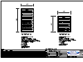
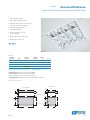
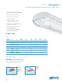
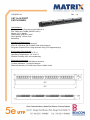
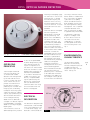
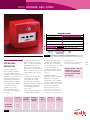
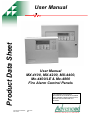
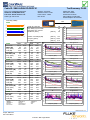
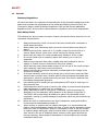
Alfa Electrical Ltd TAM House Ballymount Trading Estate Ballymount Road Lower Dublin 12 Telephone: 01-4600732 Fax: 01-4600732 ST MICHAELS HOUSE UNIT 94A LAGAN ROAD ELECTRICAL OPERATIONS AND MAINTENANCE MANUAL St Michaels House Lagan Rd Job Ref: 2009-001 Electrical O&M Manual CONTENTS SECTION 1 GENERAL DESCRIPTION SECTION 2 ELECTRICAL CENTRES AND MAINS DISTRIBUTION SECTION 3 GENERAL SERVICES SECTION 4 LIGHTING AND EMERGENCY LIGHTING SECTION 5 COMMUNICATION SERVICES SECTION 6 FIRE ALARM SERVICES SECTION 7 SECURITY SERVICES SECTION 8 MECHANICAL SERVICES SECTION 9 TEST RESULTS & COMPLETION CERTIFICATES SECTION 10 OPERATING & MAINTENANCE PROCEDURES SECTION 11 AS-INSTALLED DRAWINGS Alfa Electrical Ltd 29/01/2009 St Michaels House Lagan Rd Job Ref: 2009-001 Electrical O&M Manual PROJECT TEAM Client: St Michaels House, Technical Services Dept, 89D Lagan Road, Dublin Industrial Estate, Glasnevin, Dublin 11. Contact: Paul Kenny Tel: 01-8303161 Architects: James Smyth Architects, Booterstown Ave 10-12, Blackrock, Co Dublin Contact: Vincent Traynor Tel: 01-2882661 M&E Consultants: Clarke and Associates, Academy Street, Kildare Town, Co Kildare. Contact: Barry Nolan Tel: 045-522356 Main Contractor: Flynn Management & Contractors Ward Cross, The Ward, Co. Dublin Contact: Keith Sutton Tel: 01-8503000 Electrical Contractor: Alfa Electrical Ltd, Unit 4 Willow Business Park, New Nangor Road, Dublin 12. Contact:Paul Mangan Tel: 01-4089123 Alfa Electrical Ltd 29/01/2009 St Michaels House Lagan Rd Job Ref: 2009-001 Electrical O&M Manual SECTION 1 - GENERAL DESCRIPTION The project involves the refurbishment of the existing building at Unit 94A, Lagan Road, Glasnevin, Dublin 11 into a new training centre for St Michaels House. Upon completion the newly refurbished building shall be occupied by St Michaels House and shall have the following facilities: 2 No Meeting Rooms Training Room Independent Living Skills Library Quiet Room Training Managers Office Computer Room Managers Office Training & Drama Room Uni-sex Shower Room Open plan reception Dining & Relaxation Room Kitchen & Coffee dock 2 No Store Rooms Male & Female Toilets The Electrical Services Installation was completed by Alfa Electrical Ltd from December 2008 to February 2009. The Installation consists of the following elements: LV Switchgear General Services Installation Lighitng Installation Emergency Lighting Installation Communication Services Installation Fire Alarm Services Installation Security Services Installation Electrical Services Installation associated with Platform Lift Male & Female Toilets Alfa Electrical Ltd 29/01/2009 St Michaels House Lagan Rd Job Ref: 2009-001 Electrical O&M Manual SECTION 2 – ELECTRICAL CENTRES & MAINS DISTRIBUTION Supplier Details: Reg Farrell Engineering Unit 19 Oak Road Business Park, Western Industrial Estate, Dublin 12. Tel: (01) 4659010 Fax: (01) 4659011 Contact: Ciara John Keogh Electrical Unit 7, E.P.Mooney Buisness Centre, Longmile Road, Dublin 12. Tel: (01) 4509999 Fax: (01) 4509544 Contact: Garrett Dwyer Contents: LV Switchgear Workshop Drawings Sub Distribution Board SDB1 – Circuit Charts Sub Distribution Board SDB2 – Circuit Charts Enclosures Switchgear Protective Devices – MCB’s, RCBO’s, etc Dado Trunking – MK Prestige Plus Trunking - Unitrunk Alfa Electrical Ltd 29/01/2009 St Michaels House Lagan Road Job Ref: 2009-001 Circuit Chart Sub Distribution Board SDB - 2 Terminal 1 2 3 4 5 6 7 8 9 10 11 12 13 14 15 16 17 18 19 20 21 22 23 24 25 26 27 28 29 Terminal 30 31 32 33 34 35 36 37 38 39 40 41 42 43 44 45 46 47 48 49 50 51 Cct Ref P01 P02 P03 P04 P05 P06 P07 P09 P08 Type Sockets Sockets Sockets Sockets Sockets Sockets Sockets Sockets Sockets Sockets Sockets Sockets Sockets P16 P16 P16 P19 P20 P22 P22 P22 Location Reception Reception Dining and Relaxation Kitchen and Coffee Dock Kitchen and Coffee Dock Landing Upstairs Lift Staff Canteen IP Rated Socket Reception Spare Spare Spare Water Boiler Position for Water Boiler IP Rated 16a Socket Reception IP Rated 16a Socket Reception IP Rated 16a Socket Reception Cooker Marco Water Boiler Lift Supply Dishwasher Dishwasher Dishwasher Device 20amp RCBO 20amp RCBO 20amp RCBO 20amp RCBO 20amp RCBO 20amp RCBO 20amp RCBO 20amp RCBO 20amp RCBO 20amp RCBO 20amp RCBO 20amp RCBO 20amp RCBO 20amp RCBO 20amp RCBO 20amp MCB 20amp MCB 20amp MCB 32amp MCB 32amp MCB 20amp MCB 20amp MCB 20amp MCB 20amp MCB R S T R S T R S T R S T R S T R S T R S T R S T R S T Device 10amp MCB 10amp MCB 10amp MCB 10amp MCB 10amp MCB 10amp MCB 10amp MCB 10amp MCB 10amp MCB 10amp MCB 10amp MCB 10amp MCB R S T R S T R S T R S T R S T 6amp MCB R 20amp MCB 20amp MCB 20amp MCB R Cct Ref L01 Type Lighting L03 L04 L08 Lighting Lighting Lighting L06 L07 Lighting Lighting L05 L08 Lighting Lighting Lighting Location Stairs Leading to Reception Spare Store to Classroom Dining and Relaxation WCs Upstairs Access/ Intruder Dining and Relaxation Kitchen and Coffee Dock Roller Shutter Dining and Relaxation WCs at Entrance/ Lift Fire Alarm Sockets Sockets Sockets Control Time Clock Controlling Water Boiler Contactor Controlling Water Boiler Central Test Unit Contactors Emergency Lighting Supply IP Rated 16a Socket External Supply IP Rated 16a Socket External Supply IP Rated 16a Socket External Alfa Electrical Ltd 26/02/2009 S T 1 of 1 Box depth 300 STRUCTURE 1,5 mm steel sheet painted with RAL 7032 / 7035 textured finish. FLAT MOUNTING PLATE 2 mm galvanized steel sheet. DOOR reversible, with two square handles up to 1200 mm height, and one handle closing for 1400 mm height, painted RAL 7032 / 7035 textured finish with sealing gasket in continuous pour. GLAND PLATE Duly dimensioned, is fixed at the bottom of the box. THE SUPPLY INCLUDES structure, mounting plate, door, gland plate, all screws necessary for the assembly. Degree of protection code CE.0863 1 CE.0883 1 CE.1063 1 CE.1083 1 CE.1263 1 CE.1283 1 CE.1463 2 CE.1483 2 Dimensions Height H 800 1000 IP 65 EN 60529 UL NEMA type 4 1200 1400 Width L Depth P 600 800 600 800 600 300 800 600 800 1 - Square handle 2 - Handle UNI EN ISO 9001:2000 Impact resistance NF C 20-12-1986 IK7 In accordance with European Standards CEI EN 50298 Certification for degree of protection CEI EN 50529 Underwriters Laboratories Canada and USA - UL 508 TÜV SÜD Group 11 Certification for shockproofing OPCM 3274 20/03/2003 Miniature Circuit Breakers G60 Circuit Protection IEC 60898 IEC 60947-2 10kA Applications Performances Thermal setting In A Approval / Marking (A) 2-63 Rated voltage AC Un (V) 240/415 Minimum operating voltage UB min (V) 12 Tripping characteristics B-C-D Selectivity class 3 Mechanical/electrical endurance 20000/10000 Tropicalisation acc.to IEC 60068-2 95%RH at 55°C Terminal capacity flexible/rigid cable(mm2) Poles Add-on devices 25-35 1, 1+N, 2, 3, 4 Weight (g/pole) 120 Add-on RCD Auxiliaries Short-circuit capacity Motor operator A.20 6000 3 AC acc. to IEC 60898 Poles V 1-4 230/400 Add-on RCD Auxiliary contacts Shunt trip Undervoltage release Panel board switch Motor operator pg pg pg pg pg pg Accessories Busbars More technical data Dimensions pg A.35 pg E.1 chap. T1 pg A.36 GE Power Controls B.14 C.4 C.6 C.6 C.6 C.8 AC acc. to IEC 60947-2 Poles V 1 240 1+N, 2 127 240 2 415 3, 4 240 415 DC acc. to IEC 60947-2 Poles V 1 60 2 125 Icn/Ics (kA) 6 Icu (kA)* 10 30 20 10 20 10 *Ics = 75% Icu Icu/Ics (kA) 20 25 St Michaels House Lagan Rd Job Ref: 2009-001 Electrical O&M Manual SECTION 3 – GENERAL SERVICES Supplier Details: John Keogh Electrical Unit 7, E.P.Mooney Buisness Centre, Longmile Road, Dublin 12. Tel: (01) 4509999 Fax: (01) 4509544 Contact: Garrett Dwyer Contents: Schedule of Equipment MK Albany Plus Range MK Logic Plus Range Emergency Call System Alfa Electrical Ltd 29/01/2009 St Michaels House - Lagan Road Job Ref: 2009-001 General Services Schedule General Services Schedule of Equipment Item Manufacture Part No Supplier Switched Socket Outlets Fan Isolator Switch 20A Double Pole Switch c/w neon indicator Unswitched Spur c/w neon indicator Cooker Outlet 20A Double Pole Switch c/w neon indicator Phone Plate 1 Mod Grid Frontplate 1G Grid Frame Inter/Grid Switch 3 Gang Switch 1 Gang 2W Switch 4 Mod Grid Frontplate 4G Grid Frame 2W Grid 32 amp MCO Switch Dishwasher 32 amp MCO Switch 16 amp 4 pole IP Rated Socket and Isolator 16 amp 2 pole IP Rated Socket and Isolator MK MK MK MK MK MK MK MK MK MK MK MK MK MK MK MK MK Gewiss Gewiss John Keogh Electrical John Keogh Electrical John Keogh Electrical John Keogh Electrical John Keogh Electrical John Keogh Electrical John Keogh Electrical John Keogh Electrical John Keogh Electrical John Keogh Electrical John Keogh Electrical John Keogh Electrical John Keogh Electrical John Keogh Electrical John Keogh Electrical John Keogh Electrical John Keogh Electrical John Keogh Electrical John Keogh Electrical Alfa Electrical Ltd 26/02/2009 MK2948MCO MK4860MCO MK5233MCO MK377 MK5105 MK5423 MK0182 MK3431MCO MK3701 MK4893W MK4673MCO MK4671MC MK3434MCO MK3704 MK4882 MK5114MC MK5106 MCO DE66209 DE66204 1 of 1 Albany Plus TECHNICAL HOTLINE +44 (0)1268 563720 117 DECORATIVE 13 AMP SOCKET AVAILABLE DOUBLE POLE SWITCHING WITH NEON INDICATORS MATCHING SCREWS STYLISH CURVED DESIGN WITH WHITE INSERTS Blends unobtrusively into the environment UNIQUE 3-PIN “CHILD RESISTANT SHUTTER SYSTEM” Designed to inhibit access to the PRE-TREATED HEAT-CURED electricity supply, unless all 3 pins POWDER LACQUER FINISH of a standard British 13 Amp plug Ensures that the range is are in position durable and tarnish resistant and eliminates the Terminal screws are backed out requirement for a gasket and captive. Terminals are upwards facing to make installation easier. Funnel entrance to terminals. Clear terminal markings for easy Satin Brass finish has subtle good looks Stylish Satin Chrome finish compliments identification. to suit classic interiors. modern interior design. Logic Plus TECHNICAL HOTLINE +44 (0)1268 563720 19 WHITE CONTOURED TO DOUBLE POLE SWITCHING BLEND INTO THE Switches both live and neutral (neutral makes first, breaks WALL last) means added safety for the user OPTIONAL NEON INDICATOR SHOWS WHEN SWITCH IS ON 3mm SWITCH CONTACT GAP TASTEFUL WHITE, HIGH GLOSS, HIGH QUALITY THERMOSET MATERIAL Maintains appearance and resists scratching UNIQUE 3-PIN “CHILD RESISTANT SHUTTER SYSTEM” Designed to inhibit access to the TERMINAL MARKINGS electricity supply, unless all 3 pins of Clearly marked on all a standard British 13 Amp plug are in rear mouldings position (see note on opposite page for related products) TERMINAL SCREWS Backed out and held captive within the terminal housing IN-LINE TERMINALS Allow wire to be cut stripped to the same length FUNNEL ENTRANCE TO TERMINALS Terminals are upwards facing to make installation easier DUAL EARTH TERMINALS Available for installations that require high integrity earthing Outboard rockers on switchsockets Combined TV, FM, satellite and Simple but effective screwless cord grip reduce the likelihood of accidentally telephone sockets save on installation on connection units – securely holds the switching appliances on or off time and space cable St Michaels House Lagan Rd Job Ref: 2009-001 Electrical O&M Manual SECTION 4 – LIGHTING AND EMERGENCY LIGHTING Supplier Details: Thorlux Lighting, 1st Floor, Unit H3, Centrepoint Business Park, Oak Road, Dublin 12. Tel: (01) 4604608 Fax: (01) 4604609 Contact: Paul Ford Total Lighting, Unit 7, E.P.Mooney Buisness Centre, Longmile Road, Dublin 12. Tel: (01) 4509999 Fax: (01) 4509544 Contact: Garrett Dwyer Emerald Electrical Wholesale, 198a Whitehall Road, Terenure, Dublin 12. Tel: (01) 4099786 Fax: (0)1 4099941 Contact: David Lyons Contents: Schedule of Fittings Catalogue Cuttings Installation Instructions Alfa Electrical Ltd 29/01/2009 St Michaels House - Lagan Road Job Ref: 2009-001 Lighting Schedule Lighting Schedule Ref Item Manufacture Part No Supplier A Recessed Radiance 4*18w Body Recessed Radiance 4*18w Louvre Lamp: 18w Triphosphor, 400k Thorolux Thorolux Philips ALT 10276JF LVR10240 LMP9182 Thorolux Thorolux Philips B DOT Opal 38w, HF Lamp: 38w 2D Colour 84 Thorolux Philips 2DOT9903JF 38w22DCol84o Thorolux Total Lighting B1 DOT Opal 38w, HF with Emergency Inverter Pack Lamp: 38w 2D Colour 84 Thorolux Philips 2DOT9903JFS21460 Thorolux 38w22DCol84o Total Lighting C1 Kanby – T5 Controller 2*35w, HF Lamp: 35w, TL5, 400K Thorolux Philips KB10931 LMP10352 Thorolux Thorolux C2 CL-5 2*35w, HF Lamp: 35w, TL5, 400K Thorolux Philips CL11285JF LMP10352 Thorolux Thorolux D Thoroproof T5 1*49w, HF Lamp: 49, TL5, 400K Thorolux Philips TP11797JF LMP10353 Thorolux Thorolux E1 City Carre c/w cover III Lamp: 60 watt pl Lamp Thorolux Philips 1218500 60wPL Thorolux Thorolux E2 LED Downlighter LED Downlighter Control Module Interlink Plug (Live End) Thorolux Thorolux Thorolux SLA13587 SLA12974 SLA12982 Thorolux Thorolux Thorolux 5 ft Twin Flourescent Corrosion Proof Lamp: 58w Phillips Sylvania 2*58wCPF 58w/Col35 Emerald Emerald Safe Edge Maintained Blade Emergency Exit Sign Lamp: 8-Watt Tube Menvier Menvier SED F8W/35 Greenhills Emerald 28w 2D Golf 282D+L Lamp: 4 PIN 28W 2D LAMP Robus Sylvania RS218 L2D284P Total Lighting Total Lighting 2X26W PL DROP-GLASS Lamp: 26W PLC LAMP 4PIN 840 Robus Sylvania LDR2261-01 LPL264/84 Total Lighting Total Lighting Alfa Electrical Ltd 22/02/2009 1 of 1 Recessed Radiance TYPE A Recessed T8 luminaires for general use and VDT areas G Steel body finished white G Satin anodised aluminium louvres G LG7:2005 (<1500 cd/m2 @ 65o) and faceted crossblade louvre versions available G High uniformity lighting with radial light distribution G Fits most ceiling types, may be lay-in or pulled-up G Supplied with side arm support kit G Daylite version, see page 27 LG7:2005 Range NOMINAL SIZE (mm) LAMP LG7:2005 VERSION. FACETED VERSION APPROX. kg CIRCUIT 600 x 1200 3 x 36W T8 RRD 10260 - 16.5 D-J 600 x 1200 4 x 36W T8 RRD 10261 RRD 10267 17.0 D-J 600 x 600 3 x 18W T8 RRD 10263 RRD 10269 8.0 D-J 600 x 600 4 x 18W T8 RRD 10262 RRD 10268 8.0 D-J CIRCUIT - add suffix required: D - high frequency regulating J - high frequency e.g. RRD 10260D etc. EMERGENCY VERSION - prefix catalogue number with ‘ERR’. AUTOTEST VERSION - prefix catalogue number with ‘TRR’. Emergency and AutoTest versions add 0.7kg to weights listed. AIR HANDLING VERSION - suffix catalogue number with ‘H’ e.g. RRD 10260DH etc. LAMPS MUST BE ORDERED SEPARATELY 600mm VERSIONS 1200mm VERSIONS 53 43 1176 555 101 101 45 45 21 4 x 7 dia. holes 1197 21 597 20 x 33 slot 513 CRS. 513 CRS. 597 597 20 x 33 slot 1113 CRS. Oct. ‘08 513 CRS. 25 TYPE D Thoroproof Anti-corrosive polycarbonate luminaires for T8 and T5 lamps G High-impact and corrosion-resistant light grey, injection moulded polycarbonate body G Clear prismatic polycarbonate cover G Body and cover flame-retardant G Smooth easy-clean lines G Snug-fit polycarbonate cover clips (stainless steel option see page 42) G Fast installation via external stainless-steel brackets preserves IP rating G Optional narrow distribution reflector for rack lighting applications G Complies with M.O.D. JSP482 Chapter 8 Document for ‘Category C’ areas Range NOMINAL SIZE (mm) LENGTH (mm) STANDARD CIRCUIT EMERGENCY CIRCUIT AUTOTEST CIRCUIT 3.0 4.0 E-J-S E-J-S E-J J - 4.2 5.5 E-J-S E-J-S E-J J - 920mm centres 3.0 4.0 J J J J J J 1570 1150mm centres 4.2 5.5 J J J J J J 1570 1150mm centres 4.2 5.5 J J J - J - LAMP CAT. No. FIXINGS 1200 1 x 36W T8 2 x 36W T8 TP 10411 TP 10412 1270 920mm centres 1500 1 x 58W T8 2 x 58W T8 TP 10413 TP 10414 1570 1150mm centres 1200 1 x 28W T5 2 x 28W T5 TP 12075 TP 13400 1270 1500 1 x 35W T5 2 x 35W T5 TP 11795 TP 11796 1500 1 x 49W T5 2 x 49W T5 TP 11797 TP 11798 APPROX. kg T8 LAMP VERSIONS T5 LAMP VERSIONS FACTORY FITTED THROUGH WIRING - add ‘TW’ after catalogue number eg. TP 10411JTW CIRCUIT - add suffix required: E - electronic start J - high frequency S - switch start e.g. TP 10411E etc. EMERGENCY VERSION - prefix catalogue number with ‘ETP’. AUTOTEST VERSION - prefix catalogue number with ‘TTP’. Emergency and AutoTest versions add 0.7kg to weights listed. LAMPS MUST BE ORDERED SEPARATELY, SEE PAGE 284 FOR DETAILS DIRECT Pair of stainless steel brackets supplied. Provides clearance for thermal expansion and fixing. Oct. ‘08 PENDANT Pair of steel spring loops supplied. 43 St Michaels House Lagan Rd Job Ref: 2009-001 Electrical O&M Manual SECTION 5 – COMMUNICATIONS SERVICES Supplier Details: Beacon Communications, Unit A1, Nangor Road Business Park, Nangor Road, Dublin 12. Tel: (01) 4198485 / 4198488 Fax: (01) 4198606 Contact: Adrian Dunbar Total Lighting, Unit 7, E.P.Mooney Buisness Centre, Longmile Road, Dublin 12. Tel: (01) 4509999 Fax: (01) 4509544 Contact: Garrett Dwyer Contents: Schedule of Equipment Product Information Alfa Electrical Ltd 29/01/2009 C5E-SPEC-01 Rev 1.0 CAT 5e 24 PORT PATCH PANEL Specifications Qualified Cat.5e Permanent Link/Channel of EIA T568A and T568B (ISO/IEC11801) 24port 19” 1U Height Gold plating: gold over nickel Silver plating: 1.25um, 5um Modularity Mechanical Performance Insertion Life: 750 cycles minimum IDC Life: 200 times (22-26 AWG Solid wire) minimum Plug/Jack Contact Force: 100g minimum using FCC-approved plug. Environment Characteristic Storage Temperature: -40° to 70° C Operating Temperature: -10° to 60° C Relative Humidity: 95% non-condensing 32 44 Electrical Performance Insulation resistance: 1000 Mohms minimum Contact resistance: 7 mohms maximum Dielectric intensity: AC 1000 Vrms 50Hz or 60Hz in 60s 2 3 4 5 6 7 8 9 10 11 12 13 14 15 16 17 18 19 20 21 22 23 24 465 483 29 1 C5E-SPEC-03 CAT 5e EURO MODULE Specifications Size: 25×50×23mm Color: White Criteria: TIA/EIA T568-A Krone IDC CAT5e Mechanical Performance Material: Shell: ABS(UL94V-0) Jack: PBT Gold pin: Sn6.5-0.1(Y) Thickness of gold coated: 15um, 30um, 50um Contactor: Sn6.5-0.1(Y) Thickness of silver coated: 0.5um IDC: Copper conductor 0.4~0.64mm max. Environment Characteristic Temperature: -20°C ~ 65°C Relative humidity: max 95% at 20°C Electrical Performance Contact Resistance (excluding body resistance) ≤10mΩ (under normal air condition) Insulation Resistance:≥1000MΩ (under normal air condition) Dielectric intensity: DC 2000V, no spark over and fly arc in 1 min. Rev 1.0 St Michaels House Lagan Rd Job Ref: 2009-001 Electrical O&M Manual SECTION 6 – FIRE ALARM SERVICES Supplier Details: Siemens Limited Fitzwilliam Court Leeson Close Dublin 2 Tel: (01) 2162000 Contact: Derek Regan Greenhills Rainbow Ltd, 23A Greenhills Industrial Estate, Walkinstown, Dublin 12. Tel: (01) 4602014 Fax: (01) 4503155 Contact: Paul Tracey Contents: Schedule of Equipment Product Information Fire Alarm Panel Installation Manual Fire Alarm Panel Commissioning Manual Fire Alarm Panel User Manual Alfa Electrical Ltd 29/01/2009 St Michaels House Lagan Rd Job Ref: 2009-001 Electrical O&M Manual Fire Alarm Schedule Ref Item 2-Loop Analogue Addressable Panel Mx-4200 12-Volt 7.2 Ah Battery Apollo XP95 Optical Smoke Detector Apollo XP95 ROR Heat Detector Apollo XP95 Manual Call Point Roshni LP Sounder 24-VDC External Sounder/Strobe Apollo Integrated Base Sounder Alfa Electrical Ltd Manufacture Part No Supplier MX-12070 IE2: 55000-600 IE2: 55000-401 IE2: 55000-901 ROSHNI FLASHNI IE2: 45681 – 278po Siemens Greenhills Siemens Siemens Siemens Greenhills Greenhills Siemens Advanced Electronics Apollo Apollo Apollo Apollo 29/01/2009 XP95 OPTICAL SMOKE DETECTOR incoming and outgoing supply via terminals L1 and L2 in the mounting base. A remote LED indicator requiring not more than 4mA at 5V may be connected between the +R and -R terminals. An earth connection terminal is also provided. XP95 Optical Smoke Detector s Part Number 55000-600/620/660 Operating Principles The XP95 optical detector uses the same outer case as the ionisation smoke detector and is distinguished by the indicator LED which is clear in standby and red in alarm. Within the case is a printed circuit board which on one side has the light proof labyrinth chamber with integral gauze surrounding the optical measuring system and on the other the address capture, signal processing and communications electronics. An infrared light emitting diode within its collimator is arranged at an obtuse angle to the photo-diode. The photodiode has an integral daylightblocking filter. The IR LED emits a burst of collimated light every second. In clear air the photo-diode receives no light directly from the IR LED because of the angular arrangement and the dual mask. When smoke enters the chamber it scatters photons from the emitter IR LED onto the photo-diode in an amount related to the smoke characteristics and density. The photo-diode signal is processed by the optical ASIC and passed to the A/D converter on the communications ASIC ready for transmission when the device is interrogated. When the device is energised the ASICs regulate the flow of power and control the data processing. The optical ASIC is controlled by the communications ASIC and pulses the IR LED. The signal from the photo-diode is processed by the optical ASIC and transferred to the communications ASIC where it is then stored. When smoke enters the chamber the photo-diode signal increases. The information to the A/D converter is updated once per second or when either the monitor or the preceding address is interrogated. Whenever the device is interrogated this data is sent to the control equipment. EN54 threshold alarm levels are calibrated within the processing ASIC. If the device is not addressed within one second of its last polling and the analogue value is greater than the EN54 alarm level the alarm flag is initiated and the device address is added to the data stream every 32 polling cycles from its last polling for the duration of the alarm level condition, except when the alarming device is being interrogated. This can provide a location identified alarm from any device on the loop in approximately two seconds. The detector is calibrated to give an analogue value of 25±7 counts in clean air. This value increases with smoke density. A count of 55 corresponds to the EN54 alarm sensitivity level. See Fig. 9. ENVIRONMENTAL CHARACTERISTICS The XP95 optical smoke detector is unaffected by wind or atmospheric pressure and operates over the temperature range -20°C to +60°C. See Fig. 10. ELECTRICAL DESCRIPTION The detector is designed to be connected to a two wire loop circuit carrying both data and a 17V to 28V dc supply. The detector is connected to the Fig.7 Top section - XP95 Optical Smoke Detector page 9 XP95 MANUAL CALL POINT XP95 Manual Call Point (MCP) OPERATING PRINCIPLES The new Apollo XP95 EN54-11:2001 compliant Manual Call Point (MCP) is based on the KAC conventional MCP range. It is electronically and mechanically backward compatible with previous Apollo call points based on KAC’s World Series product. The address of each call point is set at the commissioning stage by means of a seven-segment DIL switch. Fig.16 A single bi-coloured alarm LED is provided on the call point. This LED is controlled, independently of the call point, by the control panel. The red LED is lit when the call point has been activated. An amber/yellow LED indicates a fault. Call points can be remotely tested from the panel by transmission of a single bit in the communications protocol. Call points respond by providing a value of 64 which corresponds to the alarm value. XP95 Manual Call Points are available with or without Colour Deformable Element 55100-905 Red 55100-908 Red Table 2 • • Backbox for surface Wiring Typical response characteristic - XP95 Manual Call Point an isolator. Each version is available with a resettable element and a backbox for surface mounting as standard. If a glass is required, it is available on request. For all part numbers please refer to Table 2. To provide additional protection against accidental operation, a transparent hinged cover with a locking tag, part number 26729-152 is available, which can be fitted to the manual call point. Please note that the call point does not conform to EN54-11:2001 when this lid is fitted and secured with the Pattress Isolated Box • • • Nonisolated • locking tag. For weatherproof call points see Discovery guide PP2052. Important Note – the use of lubricants, cleaning solvents or petroleum based products should be avoided. page 15 Mx-4200 Fire Panel Analogue Addressable Fire Control Panel Insert zoom image HighRes Advanced Fire Panel Technology Product Data Sheet The Mx-4200 series is fully expandable from 1 to 2 loops complete with 2 on-board sounder circuits. The control panel consists of a simple to use LCD menu driven graphical interface, dual, flashbased microprocessor technology driven by a 4 Amp power supply and charger approved to EN54 parts 2 & 4. Dedicated system navigation keys makes learning this control panel user friendly as well as installer friendly due to the uncomplicated, trouble free, commissioning and fault finding. Powerful Cause and Effect programming coupled with 'DynamiX' zoning makes the panel suitable for a wide range of site applications, from small to large complex multi area systems. Fully on site programmable via on board alphanumeric keypad or PC -Net Configuration tools. PC Software An extensive suite of PC based, software programs have been developed to supplement the Mx4000 series Fire panels. User-friendly Windows based ‘PC-NeT’ configuration software includes a virtual panel allowing for remote diagnostics via a low cost modem connection, saving time and expense for any travelling or maintenance. Features at a glance • Fully Expandable from 1 to 2 Loops • EN54 Parts 2 & 4 ‘Approved’ • Apollo/Hochiki/Nittan Protocol • 3 Year Warranty as standard • Global Compliance • Multiple Languages • Fully Networkable Key Features: Fully expandable from 1 to 2 loops via common plug in loop driver boards. Full support of Apollo (Discovery, Xplorer S90 & XP95).Hochiki ESP & Nittan Evolution protocols. Advanced graphical LCD user interface with up to 1000 fire zones as standard, allowing full EN54 compliance without additional hardware or LED indication. 4 Amp power supply and charger to EN54 part 4. Dedicated RS232 serial port for direct PC or modem connection. Dual, flash based, microprocessor technology with on-board Real Time Clock.Optional on-board or remote printer. Installer friendly 'Auto-learn' and 'Loop Detection' facility for trouble-free, commissioning.Fully on-site programmable via on-board alphanumeric keypad or PC configuration tools. Flash memory and the advanced graphical display enables the panels to be configured to operate in virtually any language with any character set and allows the installer's logo and company details to be applied to the LCD display. Robust, removable equipment chassis with plug-in connectors for simple fixing and cable termination When connected to the fault tolerant Ad-NeT network, the panel operates as a true peer-to-peer interface (with up to 1000 shared zones) with full cross panel reporting, control and cause and effect functionality. Product Data Sheet User Manual User Manual MX-4100, MX-4200, MX-4400, Mx-4400/LE & Mx-4800 Fire Alarm Control Panels The operation and functions described in the manual are available from Software Versions Mx4100-019, Mx4200-019 and Mx4400-019 onwards. Document Number: Revision: 680-015 07 ELECTRONICS LIMITED St Michaels House Lagan Rd Job Ref: 2009-001 Electrical O&M Manual SECTION 7 – SECURITY SERVICES Supplier Details: Greenhills Rainbow Ltd, 23A Greenhills Industrial Estate, Walkinstown, Dublin 12. Tel: (01) 4602014 Fax: (01) 4503155 Contact: Paul Tracey Scott and O`Shea, Units G4 & G5 Calmount Calmount Park, Ballymount, Dublin 12. Tel: (01) 4568901 Fax: (01) 4568903 Contact: Reliable Security Products Ltd Units 2 & 3 Cian Park Industrial Estate Dublin 9 Tel: (01) 8372445 Fax: (01) 8571685 Contact: Eddie Meyer Contents: Video Intercom Kit Video Intercom Handsfree Monitor Egress Button Momentary Switch Key Resetable Green BGU Electromagnetic Lock 12-Volt 1-Amp Power Supply Unit 24-Volt 1-Amp Power Supply Unit 12-Volt 7.2 Ah Battery 24v Door Retainer Alfa Electrical Ltd 29/01/2009 St Michaels House Lagan Rd Job Ref: 2009-001 Electrical O&M Manual SECTION 8 – MECHANICAL SERVICES Mechanical Contractor: JRE Group, Western Road, Clonmel, Co Tipperary Tel: 052 87400 Fax: 052 87435 Contact: John Kinsella MCC Supplier Details: McCool Controls & Engineering Ltd U12 Docklands Innovation Centre East Wall Road Dublin 3 Tel: (01) 8550532 Fax: (01) 8550546 Contact: John Kinsella Contents: Boiler House Wiring Schedule MCC Workshop Drawings & Notes Gas Detection System Alfa Electrical Ltd 29/01/2009 St Michaels House Lagan Rd Job Ref: 2009-001 Electrical O&M Manual Boiler House Wiring Schedule Equipment Ref Switch Indication / Location Boiler BO/1 Test-Off-Auto Power on/fault Burner BU/1 Test-Off-Auto Boiler house Primary Pump Calorifier Constant temperature circuit P1 Test-Off-Auto Heating Pump Zone A P2 Test-Off-Auto Heating Pump Zone B P3 Test-Off-Auto Shunt Pump P7 Test-Off-Auto Hot Water Secondary Return Pump P9 Test-Off-Auto Running/Tripped Boilerhouse Running/Tripped Boiler house Running/Tripped Boiler house Running/Tripped Boiler house Running/Tripped Boiler house Heat dissipation stat (flow header) T1 N/A Return Header Boiler house Frost immersion stat (return header) T2 N/A Flow Header Boiler house External Stat (weather compensation) T3 N/A North External Wall External Stat (frost) T4 N/A North External Wall Boiler House In Line Flow Temperature Detector Zone A T5 N/A Flow Pipe Downstream of Mixing Valve In Line Flow Temperature Detector Zone B T6 N/A Room Air Temperature Sensor Zone A T10 N/A Room Air Temperature Sensor Zone B T11 N/A Flow Pipe Downstream of Mixing Valve Heating Zone A Wall Mounted Heating Zone B Wall Mounted Calorifier Water Temperature HI/Lo control Stats T15 & T16 N/A Boiler House Motorised mixing valve Zone A MMV1 N/A Boiler House Motorised mixing valve Zone B MMV2 N/A Boiler House Motorised mixing valve Calorifier MMV6 N/A Boiler House Manual On/Off switch For Zone A N/A Admin Office Manual On/Off switch For Zone B N/A LPHW Pressurisation Unit PU-1 On-Off Admin Office Power On/Fault/Pressure Alarm PU 1 High Pressure Switch PU 1.1 N/A Integral to PU 1 PU 1 Low Pressure Switch PU 1.2 N/A Integral to PU 1 PU 1 Control Pressure Switch PU 1.3 N/A Integral to PU 1 Water Booster set WB 1 On-Off Boiler Room Gas Detection Panel GP 1 On-Off Boiler Room Alfa Electrical Ltd 29/01/2009 St Michaels House Lagan Rd Job Ref: 2009-001 Electrical O&M Manual SECTION 9 – TEST RESULTS & COMPLETION CERTIFICATES Contents: RECI Completion Cert Communication Services Test Results & Completion Cert Fire Alarm Completion Certificate Emergency Lighting Completion Certificate Alfa Electrical Ltd 29/01/2009 Cable ID: SMH LAGAN RD-DROP 01 Date / Time: 02/20/2009 08:25:55am Headroom: 8.4 dB (NEXT 36-45) Test Limit: TIA Cat 5e Perm. Link Cable Type: Cat 5e UTP Test Summary: PASS Operator: Your Name Software Version: 2.1200 Limits Version: 1.2800 NVP: 69.0% Model: DTX-1800 Main S/N: 9748109 Remote S/N: 9748110 Main Adapter: DTX-PLA002 Remote Adapter: DTX-PLA002 Wire Map (T568B) PASS 83 ft 1 2 1 2 3 6 3 6 4 5 4 5 7 8 7 8 S S PASS Worst Pair NEXT (dB) Freq. (MHz) Limit (dB) Worst Pair PS NEXT (dB) Freq. (MHz) Limit (dB) Length (ft), Limit 295 Prop. Delay (ns), Limit 498 Delay Skew (ns), Limit 44 Resistance (ohms) [Pair 45] 83 126 3 4.8 dB 60 Insertion Loss 48 36 24 Insertion Loss Margin (dB) Frequency (MHz) Limit (dB) Worst Case Margin MAIN SR 36-78 36-45 8.9 8.4 63.5 92.5 35.5 32.9 45 36 9.2 9.9 91.3 92.3 30.0 29.9 Worst Case Value MAIN SR 36-45 36-45 9.1 8.4 91.8 92.5 32.9 32.9 45 36 9.2 9.9 91.5 92.3 29.9 29.9 PASS Worst Pair ACR-F (dB) Freq. (MHz) Limit (dB) Worst Pair PS ACR-F (dB) Freq. (MHz) Limit (dB) MAIN 36-45 18.6 3.3 48.4 36 17.4 2.3 48.6 SR 45-36 18.6 2.8 49.8 36 17.4 2.3 48.6 MAIN 36-45 19.6 99.5 18.7 36 19.2 98.0 15.8 SR 45-36 19.6 99.5 18.7 36 18.7 100.0 15.6 N/A Worst Pair ACR-N (dB) Freq. (MHz) Limit (dB) Worst Pair PS ACR-N (dB) Freq. (MHz) Limit (dB) MAIN 36-78 15.8 17.9 36.1 36 16.5 18.4 32.8 SR 36-78 17.0 18.4 35.8 36 17.8 18.4 32.8 MAIN 36-45 23.9 91.8 12.9 45 23.9 91.5 10.0 SR 36-45 23.3 92.5 12.8 36 24.7 92.3 9.8 PASS Worst Pair RL (dB) Freq. (MHz) Limit (dB) MAIN 12 5.2 100.0 12.0 SR 45 5.3 50.0 15.0 MAIN 12 5.2 100.0 12.0 SR 45 5.3 50.0 15.0 Compliant Network Standards: 10BASE-T 100BASE-TX 1000BASE-T ATM-25 ATM-155 100VG-AnyLan TR-16 Active TR-16 Passive [Pair 45] 100BASE-T4 ATM-51 TR-4 12 0 [Pair 12] 15.5 [Pair 12] 100.0 [Pair 12] 21.0 dB 100 0 NEXT dB 100 80 80 60 60 40 40 20 20 0 Frequency (MHz) 100 NEXT @ Remote 0 0 Frequency (MHz) dB 100 100 ACR-F 0 dB 100 80 80 60 60 40 40 20 20 0 Frequency (MHz) 100 ACR-F @ Remote 0 0 Frequency (MHz) dB 100 100 ACR-N 0 dB 100 80 80 60 60 40 40 20 20 0 Frequency (MHz) 100 ACR-N @ Remote 0 0 Frequency (MHz) dB 60 100 RL 0 dB 60 48 48 36 36 24 24 12 0 12 0 0 Frequency (MHz) 100 Frequency (MHz) 100 RL @ Remote 0 Frequency (MHz) 100 LinkWare Version 5.0 Project: DEFAULT Site: Client Name Emerald - SMH Lagan Rd.flw St Michaels House Lagan Rd Job Ref: 2009-001 Electrical O&M Manual SECTION 10 – OPERATING & MAINTENANCE PROCEDURES Contents: Operating & Maintenance Procedures Safety Alfa Electrical Ltd 29/01/2009 OPERATING & MAINTENANCE PROCEDURES General Recommendations 1.1 Introduction Preventative Maintenance can be described as the routine inspection, testing and cleaning, adjustments and early detection of incipient trouble likely to cause breakdown. The efficient manner in which this is done can be assessed by freedom from breakdown and behavior of plant under abnormal and fault conditions. Since most of the equipment is normally static, attention is not always drawn to the dangers which can result from general neglect and it follows that a properly organised system of maintenance is essential. Maintenance problems are influenced by site and atmospheric conditions, system design and type of plant in use. The installation, testing and commissioning of equipment is all-important and must be properly supervised. This section is confined to the routine maintenance of existing plant and equipment and does not deal with the more frequent inspections and test necessary during the commissioning period and the immediate post-commissioning period. Workshop plant, machinery testing equipment, vehicles and portable compressors etc. have also been excluded Statutory regulations must be observed by those engaged on maintenance. 1.2 Object To ensure a satisfactory routine maintenance of distribution plant and equipment and also to ensure a satisfactory method of reporting and recording maintenance. 1.3 Periodic Maintenance The frequency of inspection and maintenance is given in the following sections but intervals between inspections shown in these tables may be reduced at the discretion of the Engineer, when plant is subject to severe or abnormal operating conditions to where the record shows that more frequent maintenance is essential. SAFETY 1.1 General Statutory Regulations All parties involved in the operation and maintenance of the electrical installation must be aware and act under the requirements of the Health and Safety at Work Act 2005, the Construction Safety, Health & Welfare Regulations 2006 and the General Application Regulations 2007, and any other relevant statutory regulations and current amendments. Basic Safety Points The following list, which contains a number of basic rules that should be observed, it is not necessarily comprehensive. 1. 2. 3. 4. 5. 6. 7. 8. 9. 10. 11. 12. 13. 14. Always assume every circuit is live until it has been checked with a voltmeter or similar approved means. Always check your instruments with a known live source before using them for testing. Before removing fuses, switch off or, if possible, isolate the circuit which it is serving. Never remove a fuse from a circuit carrying its working current. Never touch two sides of a circuit simultaneously whether it is live or dead. Do not use metal rules or measuring tapes when working on or near live equipment. Always use an approved fuse puller, suitably rated and insulated for the line voltage, to remove fuses on circuits which cannot be isolated. When removing fuses, always break contact on the hot side of the circuit first and when replacing, insert fuses in the cold side first. Always use tools with handgrips adequately insulated against the voltage of the circuit to be worked on. If, through necessity, work has to be carried out on a live circuit, make sure that someone else is present who is familiar with First Aid procedures associated with electrocution, and that a permit authorising the work to be done is obtained from the building management personnel. Use carbon dioxide or similar gas type extinguishers, NOT liquid or foam type, to fight electrical fires. Careful attention must be given to securing the safety of personnel and equipment while maintenance or repair work is in progress. Where maintenance work is in progress, a “DANGER” notice must always be attached to any live apparatus, calling attention to the danger of approach. A “CAUTION” notice must always be attached to plant or its associated control equipment, warning of possible damage to equipment which may be occasioned by interference. Before any work is commenced on any item of equipment, supply and ancillary circuits must be made dead and locked off. When working on medium and low voltage switchgear, it is recommended that caution notices and adequate screens are used, to prove that the apparatus is dead before any work is commenced. Where it is necessary to work on live low voltage or medium voltage switchgear, steps should be taken to guard against shock and short circuit by the use of insulating stands, screens, boots, gloves and tools as may be necessary; these should be maintained in sound condition and checked immediately before use. St Michaels House Lagan Rd Job Ref: 2009-001 Electrical O&M Manual SECTION 11 – AS INSTALLED DRAWINGS Contents: Lighting and Fire Alarm Services Power and General Services Intruder Alarm Services Electrical Schematics Alfa Electrical Ltd 29/01/2009