1
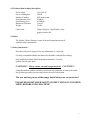
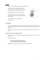
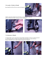
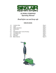
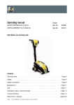
TURBO® STRIPPER II Operating Manual Read before use and keep safe Rev A Starting With Turbo II Ser# 193-07 06/21/07 (800) 624-2408 (530) 626-9386 Fax (530) 626-5144 6686 Merchandise Way Diamond Springs, Ca 95619 www.sineqco.com Table of Contents 1.0 Technical Data Page 3 2.0 Safety Page 3 3.0 Assembly & Handle Adjustment Page 6 4.0 Maintenance Page 7 5.0 Use Page 8 6.0 Information About Various Floorings Page 11 7.0 Trouble Shooting Page 11 8.0 Spare Parts/Schematics Page 15 9.0 Blade Selection Page 18 2 1.0 Technical data/technical description Power supply Power consumption Number of strokes Sound pressure level Sound energy level Hand/Arm-Vibration Weight 110-120V AC 2200W 5000 strokes/min 92 dB(A) 105 dB(A) 10 m/s2 350 lbs Comes with: Turbo® Stripper, 2 rigid blades, safety goggles and tool kit. 2.0 Safety The Sinclair Turbo® Stripper is state of the art designed and meets all standard safety requirements. 3.1 Safety Instructions Disconnect the power supply before any maintenance is carried out. Use only recommended blades and make sure the blade is sharp before starting. Only qualified personnel should undertake maintenance. Use only genuine Sinclair spare parts. CAUTION!!! Always wear ear and eye protectors! CAUTION!!! Using this machine without ear and eye protectors may jeopardize or harm your health. It may harm especially your ears and increase the risk of an accident. The user and any person within range should always use ear protectors! PLEASE READ DETAILED SAFETY INSTRUCTIONS ON COLORED SHEET BEFORE USING MACHINE! 3 Transport Always remove the blade before transporting the machine. Disconnect the power supply and the plug of the clutch before removing the handle. Otherwise you might damage the hydraulics of the clutch. Mount the steel plate (1) instead of the clutch. Turn thumb screw (3) clockwise until the drive wheels are locked. This way the machine cannot move by itself. Never transport the machine without the wheels blocked. 2.2 Introduction This operating manual should be used to receive the maximum benefit from your Turbo® Stripper. Following these instructions will both extend the life of your machine and reduce repair costs. Please make sure any user of the machine is familiar with these instructions before work begins. 2.3 Danger while working with the machine The Turbo® Stripper is designed to the highest technical standards. Incorrect use can be dangerous! Use this machine only: - As instructed in this operating manual. - With the machine in perfect working order. Disturbances that could impair safety have to be eliminated at once. 4 2.4 Restriction of use The Turbo® Stripper is exclusively for removing bonded floor covering in dry environments. It should not be used for any other purpose. Sinclair Equipment Company cannot be held responsible for any damage or loss caused by incorrect use. 2.5 Genuine Spare Parts Spare parts and accessories are manufactured uniquely for the Turbo® Stripper. It must be emphasized that parts obtained from unauthorized sources must not be used. Sinclair Equipment Company cannot be held responsible for the performance of or any damage arising from the use of machines in which genuine spare parts have not been used. This is particularly important with replacement blades. 2.6 Low-voltage Protection The Turbo Stripper is equipped with a low-voltage protection switch. The power supply breaks if current fluctuation or main power failures occur, thus preventing serious accidents. Due to the restart protection, the machine will not restart after a power failure, even if the operation switch has not been switched off. For using the protective cut-out switch see item 5.0. 5 3.0 Assembly of Machine & Handle Insert handle into Turbo II base as shown in diagram. Tighten wing bolts in handle. Note that bolts are spring loaded to get past foot pad. Position both bolts facing up as shown in diagram. 3.1 Adjustement Of Handle To adjust handle, loosen wing bolt on back of handle. Pull knob on side lever and lift torwards you. Pull locking knob out from back of handle and slide handle up or down. Release spring loaded knob where needed & tighten wing bolt. (See figures) 6 4.0 Maintenance The Turbo® Stripper is virtually maintenance free. The guide shaft castings require lubrication from time to time. (after approx. 1650 sq. feet). Initially the machine is fully lubricated and should not require any additional lubrication for the first 5000 square feet. The grease fittings are located on each side. (See Diagram 1) To Grease the gearbox on it’s right side, remove left wheel and bottom cover. Spin axel/gearbox to expose grease fitting. (See Diagram 2) Put 2 to 3 pumps to gearbox every 50 to 75 hours. The used grease will flush dirt out of the machine. Replacement lubrication should be a Lithium based chassis type lube (i.e. auto grease gun pack). CAUTION!! Press maximum of 3 times with the grease gun. Never press too much grease into the machine. Otherwise the mechanism will be blocked. Diagram 1 Diagram 2 7 Changing the blade Disconnect the power supply and put on the blade protection before changing the blade. Use work gloves for your own safety. - release bar on side of handle & tip the machine as shown - put on the blade protection - (enclosed in the tool set) Warning! Very sharp blade! You may cause injury without using the blade protection! - clean and loosen screws of the blade mounting Attention! Set the wrench at a position opposite to the blade to avoid injury. - replace the blade Make sure that the blade fits in exactly into the support. On normal and hard sub floors the bevel of the blade should show upwards (1), on soft sub floors the bevel should show downwards (2). Changing the driving wheels Remove the lynch-pins and pull the wheels from the axle. Do not loose the wheel key under any circumstances! 5.0 Use The Turbo® Stripper removes any bonded floor coverings in strips. This procedure corresponds with the customary method of using a hand floor scraper. The stripper works with a steel blade at very high frequency, minimizing vibration and noise. The Turbo® Stripper is self-propelled. The motor actuates both the blade and the machine movement. The blade drive starts as soon as the machine is switched on The hand clutch will engage the drive. Starting 8 The Turbo® Stripper is equipped with a Power -on indicator lamp (1) and an operating Switch located at the top of the handle. The switch has a restart protection for low-voltage failures. If the lamp does not indicate power-on, use another power socket or check power supply. Before starting work, cut the floor covering into strips of about 12 “. You cannot work faster if you cut wider strips. To begin, cut one strip crosswise. Then lift the flooring slightly in order to get the blade underneath it. We recommend to cut the first strip at right angles to the main working direction. By so doing access to the adjacent strips is made easier. Cut the strips smaller if the floor covering is bonded very securely, e.g. with an epoxy adhesive. The blades are sharpened by the floor pavement. Therefore the blade has to be changed only if it is twisted or becomes worn. The driving wheels are subject to wear. They have to be changed after approximately 16mm (0.6 inch) of the surface has been worn away. Otherwise the working angle of the striking apparatus will not be correct especially critical with cork or foam backed carpets. 9 Assembly of support for additional weight (accessory) The weight of the Turbo Stripper is expandable by 1 up to 3 additional weights (each weight is 66 lbs) Sinclair part# T38535 Individual weight shifting is possible at 3 positions (see picture). 10 Emergency running The Turbo Stripper can be operated also with broken or damaged hand clutch as follows: - Disconnect power supply - Insert emergency-run-unit in place of clutch. - Screw-in thumb-screw (3) until the driving wheels are blocked - If the emergency-run-plate is mounted, the motor drive is always switched on. The machine starts running immediately after switching on. 6.0 Information about various floorings Carpets with foam backing A sharp blade is essential in order to ensure the floor covering is removed together with the foam backing. Remove floorings across the width, particularly if you have any uneven sub-floor. Tiles Use blade of the same width as the tiles and use a new blade. Tiles above size 30 x 30 cm (12 x 12 inch) has to be cut into half. If the sub-floor is uneven, use smaller blades. In all cases, check from time to time to ensure the blade is still sharp. If it is not or any distortion has occurred, replace it immediately. 7.0 Trouble shooting 1. Make sure the machine is connected to a known 120V, 20-amp circuit breaker. 2. All plugs should be firmly connected. Check for any splits or damage to power cord. 3. Failure in Hydraulic Clutch System. (see 7.1) Note: In the event of Hydraulic Clutch failure, the Emergency Run Unit can be inserted in place of the hydraulic cylinder. This will allow continued use of the machine without clutch availability. The machine will need to be turned off to move into a new position. 11 7.1 Repairing the Hydraulic System To repair the hydraulic system, use the Sinclair Hydraulic Clutch Repair Kit, which can be ordered through your local distributor. Hydraulic Clutch Repair Kit This kit contains all hydraulic fittings, compression washers, tubing, fluid, and specific tools necessary to completely rebuild the Turbo® Stripper’s hydraulic clutch assembly. Not included in the kit is a master cylinder and slave cylinder. If either of these components are damaged and required replacement, you can purchase a complete hydraulic assembly from Sinclair Equipment Company. The hydraulic fluid provided with the kit is a non-toxic, biodegradable, mineral oil based product, and no special handling or disposal requirements are necessary. You should not, however, accept any substitutes. Automotive brake fluid and other petro-chemical or glycol based hydraulic products are caustic, will deteriorate the tubing and internal working parts of this system, and should not be used. Repairing the Hydraulic System The kit includes two nylon blocks with grooves cut in them to assist in installing the barbed fittings on the tubing ends. Using a sharp knife cut the end of the tubing to be installed as clean and square as possible. In a vise, clamp the end of the tube in the nylon blocks, allowing about 1/2 inch of tubing to stick out past the end of the blocks. Using a plastic mallet or similar lightweight hammer, tap the barbed, 90 degree (banjo shaped) fitting into the end of the tubing as far as it will go. Before installing a fitting on both ends of the tubing, make sure that the spring-like cable sheath #1 for both ends are in place on the tubing. For a more reliable repair, you should always replace all fittings and compression washers with each new assembly. Each 90-degree connection requires two washers and the slave cylinder bleeder screw needs one. Measuring the tubing length and installing the tube is best done with the master and slave cylinders installed on the machine. The idea is to mount the 90-degree connectors in the proper direction and with enough tubing to avoid stressing the barbed fitting/tubing connection during normal use. 12 Filling and Bleeding The System Turn the clutch adjustment screw #2 (2mm Allen screw, located in the handle behind the lever of the master cylinder #7) counterclockwise as far as it will go. Insert the straight barbed adapter into the top end of the clear tubing and insert the tip of the syringe into the bottom end of the tube. Fully depress the syringe’s plunger to expel all air, dip it in the fluid and draw the plunger back slowly to fill the syringe at least half way. Remove the bleeder screw #3 from the slave cylinder #8 at the rear of the machine and attach the syringe assembly in its place. Remove the bleed screw #4 (plug) from the master cylinder and depress the syringe’s plunger to force fluid through the system. Allow enough fluid to flow from the master cylinder, to ensure that no air remains in the system. If desired, the master cylinder can be removed from the machine’s handle and placed in a rag. Care must be taken, however, to maintain adequate altitude between the cylinders, to ensure the absence of air. Always fill from bottom to top. In the following order: 1. Replace and tighten the plug in the master cylinder #4; 2. Remove the syringe assembly from the slave cylinder; and 3. Reinstall the bleeder screw #3, using a fresh compression washer. Wipe clean any excess fluid. Mount the master cylinder on the handle, if necessary, and test the function of the hydraulics. Adjustments can then be made by tightening the adjustment screw on the master cylinder #2. If the master cylinder is too tight, you can allow some fluid to escape by loosening the master cylinder bleeder plug #4, and gently squeezing the lever very slightly to allow a few drops of fluid out. To avoid allowing the cylinder to suck in air, be sure to tighten the bleeder plug securely before releasing any pressure applied to the lever #5. The adjustment can then be made using the adjustment screw #2. The clutch must engage fully and remain engaged when you set the lever lock #6. 13 Turbo Hydraulic Clutch Parts 1. Hydraulic Tubing – T099998T (Order qty 42) 2. Master Cylinder with Lever. (#2)- T0730236 3. Screw for Clamp – T0999996 4. Clamp – T0999995 5. Lever Blade W Plunger & Lock – T0999994 6. Slave Cylinder – T0321830 7. Protective Spring – T0999992 Complete Hydraulic Clutch Assembly – T015032 Clutch Rebuild Kit – T0999998 14 Spare Parts/Schematics Schematic # 1 4 5 6 8 12 13 14 15 16 19 20 21 22 23 24 25 26 27 28 29 30 31 32 33 34 35 36 37 38 39 41 42 44 45 46 47 48 49 52 53 54 57 58 59 61 62 63 64 Description Chassis Piston block Screw M 8x30 Washer, M8 Lubricating nipple Cover Screw M 8x25 Additional Weight Screw M10x80 Screw Nut Bushing 20x26x20 Blade holder Turbo / Jaw Striking foot Turbo Cyl. screw M8x20 - 6mm Screw M10x25 Tension pin 10x20 Piston rods Washer, M13 Screw M 12x30 Connecting block (Left or Right) Washer 18mm Wheel pin Washer, 16 mm Drive wheel B16 Gear mounting block right Screw M 10x45 Safety washer, 10 mm Clutch holder Clutch stop device Pressure bolt Emergency run unit Pressure spring D 206 Pressure spacer Thread pin M5x10 Cyl. pin 6x32 Washer M6 Clutch disc Gear block Drive belt small Drive shaft axle Key 5x5x32 Gear mounting block left Nylon Transport Wheel Split-pin 3, 2 x 32 Carriage Bracket Nut key 6x6x32 Connecting rod W/ PIN Connecting rod pin Ball bearing 6206 Part# T015106 T015054 T014736 D014860 T014914 T038534 T014735 T038535 T039234 T039189 T014909 T038536 T015127 T014734 T014763 T014890 T015132 T014833 T014744 T015417 T014832 T014888 T014851 T015135 T015033 T014741 T014861 T040003 T040006 T015120 T016232 T040002 T042681 T014791 T014874 D014859 T015119 T015140 T014938 T015142 T014902 T015036 T041888 T014886 T042612 T014904 T015144 T014875 T014710 15 65 66 67 68 69 70 71 72 73 75 76 77 78 79 80 81 82 83 84 85 86 87 88 89 90 91 92 94 95 96 97 98 99 100 101 102 103 104 105 106 107 108 109 110 113 114 115 116 117 118 122 123 125 Circlip I 62 Circlip A 17 Ball bearing 6305 Circlip A 30 Excenter shaft Turbo Nut key 4x4x20 Key 6x6x25 Circlip A 25 Bearing block right or left Screw M 10x70 Cyl. pin 8x40 Motor 2400 Watt - 110 Volt Belt Pulley Z20 Electrical cord with plug Motor Plate, new Screw M 5x25 Washer, 5 mm Spacer Drive belt large Handle Bracket Outer tube Inner tube Electrical cord short Clamping lever Arresting bolt Stopper Cyl. Screw Cover Grip Screw M6x12 Electrical cord long Belt pulley Z 24 - Large Belt pulley Z 12 - Small Washer Groove ring Hexagon bolt Cyl. screw M 6x25 Washer, M12 Starter disc / PVC Washer Weight Bracket Switch housing Switch housing cover Clamping Lever M10x50 Oval Head Screw M16 x 16 Motor cover (neu) Bracket Screw M 5x90 Neu Bushing 20x26x11 Bushing 20x26x30 Washer M6 Cyl. screw M8 X 35 Cable pit Cyl. Screw M4 x 12 T014856 T014850 T014712 T014853 T015145 T014901 T014903 T014852 T017079 T014742 T014876 T015056 T015129 T014973 T016860 T014721 T014858 T015150 T014937 T038531 T038508 T038509 T014974 T038567 T037953 T018800 T014734 T015154 T039233 T014799 T014970 T015155 T015156 T014828 T014845 T018135 T014731 T014862 T015164 T042741 T038507 T038505 T038566 T017621 T015130 T038606 T014724 T015141 T014910 T014835 T014737 T039188 T018284 16 126 128 129 131 132 133 136 137 138 139 140 141 142 146 147 148 149 150 151 176/177 178 179 180 181 Hydraulic-clutch assy Transport Axle Strain relief Handle Cyl. Screw, micro M6 x 20 Bracket for Lifting Strap Cyl. Screw, M8 x 16 Washer Indicator Cyl. Screw, M6 x 60 Fitting Elastic Stop Nut M8 Belt pulley Switch Top Hat Rail Cyl. Screw M6 x 105 Grip covering Screw M 4 x 8 Push button Twist lock assy Countersunk head screw Tilt Support Split Washer Shoulder Bolt T038837 T042739 T017559 T014917 D014752 T015107 T017651 T017452 T038638 T018259 T038585 T014816 T014848 T017439 T020969 T039284 T038568 T017473 T021233 T015046 T017701 T039636 T014844 T021232 Without Drawing: Tool Kit Motor Brush Set Transport Wheel Ass'y-Complete Hydraulic Clutch Repair Kit 2016 Bushing (for T28/T29) Hydraulic Mineral Oil 2oz Lifting Straps T015162 T025768500 T044066 T0999998 T014913 T0999999 T040603 17 TURBO, EXTRO, SUPER, BRAVO, DURO & ECO STRIPPER SUGGESTED BLADE SELECTION BRAVO/DURO/ECO STRIPPER #10-4906 8”Rigid. Our standard blade for removal of vinyl, carpet, adhesive, etc. Bevel edge of blade should be up for concrete and down for wood sub-surfaces. Precutting of carpet and vinyl needed. #10-4904 8”Flexible. Same as above, yet for uneven concrete surfaces and some soft foam back carpet. #10-4907T 8”Tile Blade. For use on VAT and VCT tile. Prevents tile from jamming in between blade and blade holder. A must for tile removal to protect blade holder. #10-4909 8”Razor Blade Attachment. An adapter to secure razor blades for removal of adhesives, paints and thin films. Inexpensive and an excellent choice for complete clean up after floor covering removal. #10-4903 8”X 5”Rigid. Ideal for hard to reach areas such as toe kicks, under radiators, etc. Also used for clean up of small areas of parquet, ceramic, etc. #10-4906D 8”X 2.5”Rigid Self Dicing. For use on carpet, rubber or vinyl. A real time saver, on pre-cutting necessary since blade will cut strips with knife edged sides. TURBO/EXTRO/SUPER STRIPPER *Super Stripper uses 12” Blades Only #10-4801D 14”Self-Dicing Blade. For use on carpet, rubber or vinyl. A real time saver, on pre-cutting necessary since blade will cut strips with knife edged sides. #10-4651T 12”Tile Blade. For use on VAT and VCT tile. Prevents tile from jamming in between blade and blade holder. A must for tile removal to protect blade holder. #10-4807 14”X 5”Ceramic/Parquet Blade. Ideal for removal for ceramic tile, marble, parquet, and other wood floors. Precutting needed for plank floors. #10-4809 Special Ceramic/Parquet Blade. This ¼” thick heavy duty blade is designed especially for the ceramic tile and hardwood/parquet removal applications. The 14” wide blade extends out nearly 4” and is designed at a specific angle to work more efficiently in cutting and lifting of thick materials. Best suited for the long run, constant use in tile/wood applications for extended life and performance. #10-4802 14”Rigid, #10-4652 12”Rigid. The standard blade for carpet, vinyl or adhesive removal, precutting of the floor is needed. #10-4804 6”Rigid, #10-4803 8”Rigid. Use these blades for difficult removal like, epoxy, rubber floors, sport surfaces, etc. Always position these blades to far left hand side of machine. NOTE: All jobs can vary in difficulty of removal. Whatever blade you are using it may be necessary to take a smaller bite in removal so it is less stressful on the operator as well as the machine. If you have any questions on blade selection or choice of machine, please do not hesitate to call Sinclair Equipment Company or your nearest distributor. 18 STANDARD WARRANTY SINCLAIR EQUIPMENT COMPANY’S tools are warranted to be free of defects in workmanship and materials for a period of one year from the date of original purchase. Should any trouble develop during this one year period, return the complete tool, freight prepaid, to SINCLAIR’S authorized Service Center. If inspection shows the trouble is caused by defective workmanship or materials, SINCLAIR EQUIPMENT COMPANY will repair, or, at its option, replace without charge. • This warranty does not apply to malfunctions caused by damage, unreasonable use, faulty repairs made by others, or failure to provide recommended maintenance. • The warranty is void if the product is altered by the original consumer purchaser, or if it is used in a manner not recommended by the manufacturer. • The warranties do not cover consequential damages or transportation charges incurred with the replacement or repair of SINCLAIR EQUIPMENT COMPANY products. • Not responsible for lost job or down time. In no event shall SINCLAIR be liable for any indirect, incidental, or consequential damages from the sale or use of the product. This disclaimer applies both during and after the term of this warranty. SINCLAIR EQUIPMENT COMPANY disclaims liability for any implied warranties, including implied warranties of “merchantability” and “fitness for a specific purpose”, after the one year term of this warranty. This warranty gives you specific legal rights, and you may have other rights which vary from state to state. Should you have any questions, contact SINCLAIR EQUIPMENT COMPANY at (530) 626-9386. To obtain warranty service, deliver or send the complete tool, prepaid, to SINCLAIR EQUIPMENT COMPANY. Be sure to include the following information: • • • • Nature of failure; Name and address of distributor where tool was purchased; Application of tool when rendered defective; and Proof of purchase. To obtain individual repair parts, contact SINCLAIR EQUIPMENT COMPANY with the following information: • • • Tool model number; Item part number; and Description of part. 19 Notes 20