1
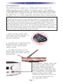
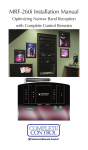
MRF-260 Installation Manual
Optimizing Narrow Band Reception
with Complete Control Remotes
COMPLETE
CONTROL
™
Universal Remote Control®
MRF-260 Installation Manual ©2007 Universal Remote Control, Inc.
The information in this manual is copyright protected. No part of this manual may be copied or reproduced in any form without prior written consent
from Universal Remote Control, Inc.
UNIVERSAL REMOTE CONTROL, INC. SHALL NOT BE LIABLE FOR OPERATIONAL, TECHNICAL OR EDITORIAL ERRORS/OMISSIONS MADE IN
THIS MANUAL.
The Home Theater installation on the cover was designed and installed by
Stone-Glidden of King of Prussia and Doylestown, PA.
The information in this manual may be subject to change without prior
notice.
Complete Control is a registered trademark of Universal Remote Control,
Inc.
All other brand or product names are trademarks or registered trademarks
of their respective companies or organizations.
500 Mamaroneck Avenue, Harrison, NY 10528
Phone: (914) 835-4484 Fax: (914) 835-4532
TABLE OF CONTENTS
Introduction
1
Features and Benefits
2
Parts Guide
2
Installation
3
Testing
5
Front Blaster Overload
6
Disabling the Front Blaster - Step by Step via PC
6
Controlling Four Identical Components/Zones
7
Identical Components/Zones - Step by Step via PC 7
Programming For Multiple Equipment Locations
10
USA Limited Warranty Statement
11
Frequently Asked Questions
12
Specifications
12
MRF-260 BASE STATION
Introduction
The MRF-260 base station is an “addressable” base station. RF
Addressing gives you the ability to control as many as 60 identical
components throughout a house. To enable better range and reliability the MRF-260 is equipped with the Narrow Band RF reception (like
the MRF-350), so is only compatible with other Narrow Band remotes.
NOTE: The MRF-260 is ONLY compatible with Narrow Band remotes: the
current versions of the MX-3000, MX-950, MX-900, TX-1000, MX-850, MX-650
and the MX-350 remote controls. The MRF-260 is compatible with all MX950s, MX-900s and TX-1000s, but is NOT compatible with MX-850, MX-650
or MX-350 remote controls manufactured before November 1, 2006 or an
MX-3000 built before April, 2005. You can identify the build date of a remote
control by looking at the serial number. The first 6 digits indicate the build
date. If the serial number appears as 122905 014054, the first 6 digits indicate
that the remote was built on December 29, 2005.
1. MX/TX remote controls send
radio waves in every direction, so
your client enjoys “No More
Pointing” operation!
2. The MRF-260’s integrated Narrow
Band RF receiver receives commands from any Narrow Band
remote control.
3. The MRF-260’s built-in Front
Blaster sends commands to components in the same cabinet space as
the MRF-260.
4. Self-adhesive “Flashers” affix to the
front panels of your client’s components (over the built-in IR sensor).
The Flashers relay commands to
components out of sight of the MRF260’s Front Blaster. The flashers plug
in to the MRF-260’s rear flasher line
outputs via their 10 foot cables.
Uniquely, the MRF-260 can also connect to rear panel IR Inputs via its
two adjustable Outputs.
Page 1
MRF-260 BASE STATION
Features and Benefits
Interference Rejection and Extended Range via Narrow Band
The MRF-260 receives RF (radio frequency) signals via its integrated
RF receiver and antenna. The MRF-260 displays RF interference via a
bright red Status LED, which flickers when interference is present if the
ID is set to 0. Simply relocate the MRF-260 should interference occur.
Two Fixed IR Outputs
The MRF-260 is equipped with two fixed IR line outputs with standard
3.5 jacks for standard IR emitter/flashers.
Two Variable IR Outputs Match Rear Panel IR Inputs
The MRF-260 is equipped with two adjustable IR line outputs. Each
output can be individually matched to rear panel IR inputs on any
component that is designed to be operated by a standard IR repeater.
The outputs utilize a 3.5mm jack and are compatible with standard IR
emitter/flashers as well.
Up To Fifteen Equipment Locations With Identical Components
Each MX/TX remote is “addressable.” They can be programmed to
specifically control components in a particular room by installing an
MRF-260 base station at each location. In operation it’s simple: when
you select a device located in the Den, the MX/TX remote only sends
commands to the Den. When you select a device located in the
Family Room, the MX/TX remote only sends commands to it.
A Single MRF-260 Can Control an Array of Identical Components
or Identical Zones of a Multi Zone Preamp/Matrix Switcher
Each MRF-260 has four “addressable” IR Line Outputs. For example,
you can control up to four identical TV’s with one MRF-260 or route
volume commands for a specific zone to a particular zone IR input on
a multi-zone preamp. If you have more than four identical components or zones, up to 15 additional MRF-260s can be installed to control them (thus allowing up to 60 identical components or zones in
one house).
Parts Guide
The MRF-260 RF Base Station includes:
1 - MRF-260 Base Station
1 - Mounting Plate for wall mounting
the MRF-260
4 - Screws for wall mounting
1 - 9V-300mA Power Supply
4 - Visible Flashers with 10 foot plug in
cables.
4 - Extra self adhesive pads for
Emitters
12 - Labels for IR Line Outputs
1 - Screwdriver for Variable Outputs
Page 2
MRF-260 BASE STATION
Installation
1. Unplug the MRF-260. Test all IR commands and macros line of
sight.
2. Power on all AV components including the TV. Turn on all of the
lights and lower all dimmers to 50%. Power on anything that
may create RF Interference (particularly devices with high speed
microprocessors or hard drives).
3. Check that the address wheel on the rear of the MRF-260 is set
to ID#0 (the interference “sniffing” position).
Check that the arrow pointer in the center of the wheel is pointed to 0, the
default “interference sniffing” position. If it is not, use a small flat blade
screwdriver (included) to set the RF ID# to 0.
4. Connect the MRF-260 to its DC wall adapter and plug the wall
adapter into a live AC outlet. Place the MRF-260 in a location at
least 3 feet away from satellite receivers, cable boxes, HDTV
tuners, DVRs, PCs or any other device with a high speed microprocessor (these generate broad band Radio Frequency
Interference -RFI). Of course, you should keep in mind that the
emitter cables are 10’ long.
The green POWER LED indicates that the MRF-260 is
powered on.
The red STATUS LED flashes
differently, based on the
Address setting:
IF SET TO ID#0
The Status LED flashes
when it receives ANY RF
signal, including RFI. This
makes ID#0 ideal for “sniffing” out RFI.
IF SET TO ANY OTHER ID#
The Status LED flashes ONLY
when it receives a correctly
addressed RF command.
Page 3
MRF-260 BASE STATION
5. Observe the Status LED of the MRF-260. If it is glowing or flickering you must relocate the MRF-260 to a location where the
LED doesn’t flicker.
If your installation location simply doesn’t offer you any choice
and you are detecting interference everywhere you place the
MRF-260, you have two last resort options:
a. Remove the MRF-260’s antenna. This will reduce the
range enormously, but may still be enough for this client.
b. Admit defeat and install the two piece MRF-350 base
station, which can have the RF Antenna module remotely located (even in another part of the house).
7. Once you have found a location that is absolutely free of RFI
with everything on, test to see if the range is adequate and that macro reliability is perfect. Start
with the antenna angle set to 45 degrees and positioned so that the long side of the antenna is fac45°
ing the customer’s favorite seating position.
When testing, set both the remote and the MRF-260 to the same
valid RF ID#. Keep in mind that zero (0) is not a valid RF ID#.
Watch the Status LED on MRF-260 - it should light every time
you press a button on the remote. This confirms that the signal
was received and understood perfectly. If you repeat any button
press multiple times and the Status LED lights correctly every
time, you have no interference and a very reliable installation. If
some of the presses do not light the Status LED, you still have
some RFI. Your best strategy is return to step 3 and try to find a
better location for the MRF-260.
8. Now that the location is fixed, connect each of the emitters to
the appropriate IR output and run the cable to the appropriate
component. Do not attach the emitters to the front panel yet!
Utilize the included preprinted labels to identify which emitter
goes to which component. If you’d like to make your own, the
slots for the labels have been sized at 12mm to enable a Brother
P-Touch 12mm label to fit perfectly.
NOTE: TiVo, Replay TV, other DVRs, Satellite Receivers and Cable
Boxes are all extremely sensitive to IR overload or saturation. For
this reason, it is recommended that you always connect the IR
flashers for these types of component to the Variable IR Outputs of
the MRF-260.
Page 4
MRF-260 BASE STATION
Testing
Test a few commands for each device before fixing the flasher in
place on the front panel of a device.
Since TiVo, Replay TV, Satellite Receivers and Cable Boxes are all
extremely sensitive to IR overload or saturation, you should test
them thoroughly. Put up the on screen guide and test the navigation
arrows. Compare operation via RF to the original remote control.
Operation should be identical. RF is not slower. If operation is
inconsistent or sluggish, lower the IR line output and/or reposition
the flasher.
If you still have sluggish operation, check that the remote control is
set to a particular LINE OUT, rather than ALL. When IR commands
are sent to all the flashers in a cabinet, you can have difficulty
adjusting the IR Output. Reprogram the remote control to send IR
commands only via a specific (1-4) Line Output, then readjust the
IR Line Output level.
Note: Remember, the MRF-260 will NOT respond if you select IR
line outputs 5 or 6. The MRF-260 has only four IR Line Outputs.
1. Connect an IR emitter to each IR output and run the emitter
wire to the front panel of each component. DO NOT STICK the
emitter in place. ADJUST the level first.
2. Adjust each of the IR Output levels for best operation. If the
component operates best at minimum level, but is still operating
sluggishly or intermittently, move the emitter farther away from
the components IR sensor.
Page 5
MRF-260 BASE STATION
Front Blaster Overload
A few models of audio/video components can be overloaded by the
Front Blaster. If you are having intermittent or inconsistent results
with a particular component, try repositioning the MRF-260 and
facing the Front Blaster in a different direction. If this improves the
situation but is impractical, it may be necessary to utilize the selfadhesive flashers only and follow the steps below to Disable the
Front Blaster. This will limit the number of components your MRF260 can control to four. If you have more than four components
you can purchase an additional MRF-260 or upgrade to an MRF350.
Disabling the Front Blaster - Step by Step via PC
Note: If you are programming a URC MX “addressable” remote
control that sets up without a PC, refer to the owners manual to disable the Front Blaster.
Open the PC software, then plug the MX PC programmable remote
control into the PC. Open your saved configuration and follow
these steps to turn off the front blaster:
Step 1 - Open the RF Setup Window
The RF Setup window opens after selecting RF Control or Settings
from the Program Menu of most MX/TX editors or from the Main
Menu of the ProWizard.
Step 2 - Setup the Receiver
Extend the RF Setup window by clicking on the
RECEIVERS button.
Step 3 - Turn off the Front
Blaster
Click on the cell in the IR
LED OUTPUT/IR BLASTER
column. A list box will
appear. Select OFF from
the list.
Next, click on Close to apply your change.
Page 6
MRF-260 BASE STATION
Controlling Four Identical Components/Zones
There are several considerations to take into account when you are
installing an MRF-260 to control an array of identical components:
1. The RF ID# cannot be set to Code 0, the universal setting. You
must use one of the fifteen unique IR Routing addresses.
2. Each identical component must receive IR commands ONLY
from a dedicated Flasher affixed to its front panel or a rear panel
direct IR input. The SIGNAL of the remote should be set to RF
ONLY for each identical component. IR can still be utilized for
other devices in your system!
3. You must note the NUMBER of the Flasher Output you have utilized for EACH of the identical components.
Identical Components/Zones - Step by Step via PC
Step 1 - Create and Program a Device for Each Component/Zone
Try to name each device with a descriptive title. At a minimum,
label them TV1, TV2, TV3 and so on.
Step 2 - Open the RF Setup Window
The RF Setup window opens after selecting RF Control from the
Program Menu or from the ProWizard’s Main Menu. The RF Setup
window is composed of a “spread sheet” of options for EACH of
your devices.
Page 7
MRF-260 BASE STATION
By looking at the Signal column, you can see that the factory
default programming sets all of the devices to send both IR and RF
commands. If you look at the column for Flashers, you can see that
the default sends IR commands for all devices to ALL of the flashers. Both options must be changed for identical components.
Additionally, you must disable the Front Blaster (see page 6 for
directions).
Step 3 - Adjust the Signal For Each of the Identical Devices
The RF Setup window enables you to adjust the Signal output for
each device individually, by clicking on the intersection of a row
and a column and then selecting RF from the three options shown
in the pull down list box.
Select RF from the three options shown for EACH of the identical
TVs. You may leave the other components of the system set to IR
& RF.
Step 4 - Adjust the Flashers For Each of the Identical Devices
The RF Setup window enables you to adjust which Flashers output
by the remote control for each device individually, by clicking on
the intersection of a row and a column and then selecting 1-4 from
the seven options shown in the pull down list box.
Select the correct Flasher (refer to your connection notes) for
EACH of the identical TVs. You may leave the other components of
the system set to ALL.
See figure on the next page.
Page 8
MRF-260 BASE STATION
In the figure below, each device is set to a specific flasher.
Note: Remember, the MRF-260 will only respond to selections 1
through 4.
Step 5 - Make sure that the ID# is set on both the remote and on
the wheel of the MRF-260.
Click on the Receivers button and set the RF address to one of the
first 15 addresses (1-9 or A, B, C, D or E). The second set of addresses is only supported by MSC units.
Step 6 - Close the RF window and Download to the Remote.
Page 9
MRF-260 BASE STATION
Programming For Multiple Equipment Locations
You can operate up to 15 different equipment locations, each with
an MRF-260 assigned a unique Receiver ID#. You program each of
your remotes to talk to the equipment locations you want by assigning each of your devices to a receiver. First, you must add and
name your receivers for the locations they are placed in:
Step 1 - Open the RF Setup Window
The RF Setup window opens after selecting RF Control from the
Program Menu or RF Settings from the Main Menu of ProWizard.
Step 2 - Reveal the Receiver settings
Extend the RF Setup window by clicking on the Receivers button of
the RF setup window.
Step 3 - Add, Name and Assign Receiver ID#
Using the controls at the bottom extended portion of the RF Control
window, add new receivers and rename them for the equipment
location.
Add new receivers by clicking on the Add button.
Assign the correct Receiver ID# for
each LOCATION by clicking on the
desired CELL and selecting the ID#
you want from the pull down list.
Each LOCATION should have a
unique ID#. It is ok to install multiple MRF-260’s in one location.
Delete receivers by selecting them
first by clicking on their Name,
then clicking the Delete button.
You may rename the Default
receiver to something more
descriptive by clicking on
the Rename button.
Step 4 - Save and Download to your
remote.
Page 10
MRF-260 BASE STATION
USA Limited Warranty Statement
Your Universal Remote Control, when delivered to you in new
condition, is warranted against defects in materials or workmanship as follows: UNIVERSAL REMOTE CONTROL, INC.
warrants this product against defects in material or workmanship for a period of one (1) year and as set forth below.
Universal Remote Control will, at its sole option, repair the
product using new or comparable rebuilt parts, or exchange the
product for a comparable new or rebuilt product. In the event
of a defect, these are your exclusive remedies.
This Limited Warranty covers only the hardware components
packaged with the Product. It does not cover technical assistance for hardware or software usage and it does not cover any
software products whether or not contained in the Product; any
such software is provided "AS IS" unless expressly provided for
in any enclosed software Limited Warranty.
To obtain warranty service, you must deliver the product,
freight prepaid, in its original packaging or packaging affording
adequate protection to Universal Remote Control at the address
provided in the Owner's Manual. It is your responsibility to
backup any macro programming, artwork, software or other
materials that may have been programmed into your unit. It is
likely that such data, software, or other materials will be lost
during service and Universal Remote Control will not be
responsible for any such damage or loss. A dated purchase
receipt, Bill of Sale, Installation Contract or other verifiable
Proof of Purchase is required. For product support and other
important information visit Universal Remote Control's website:
http://www.UniversalRemoteControl.com or call the Universal
Remote Control Customer Service Center (914) 835-4484.
This Limited Warranty only covers product issues caused by
defects in material or workmanship during ordinary consumer
use. It does not cover product issues caused by any other reason, including but not limited to product issues due to commercial use, acts of God, third-party installation, misuse, limitations of technology, or modification of or to any part of the
Universal Remote Control product. This Limited Warranty does
not cover Universal Remote Control products sold as USED, AS
IS, REFURBISHED, so-called "B STOCK" or consumables (such
as batteries). This Limited Warranty is invalid if the factoryapplied serial number has been altered or removed from the
product. This Limited Warranty is valid only in the United States
of America. This Limited Warranty specifically excludes products sold by unauthorized resellers.
Page 11
MRF-260 BASE STATION
Frequently Asked Questions
Can I use flasher/emitters that I have already installed in the system to connect to the MRF-260?
Yes, the flashers are compatible if they use 3.5mm mono mini plugs with
the same polarity (Tip is data, sleeve is ground).
I’m getting inconsistent operation regardless of flasher level or
position.
Some components are easily overloaded with IR from nearby flashers.
Prevent IR from affecting the problem component from other flashers or the
front panel blaster by setting the device to a specific IR Line Output instead
of ALL, then adjust the Line Output.
I have a row of identical TVs. I’ve correctly set the flasher outputs
using the Editor software, yet when I send a command to one of
them, the TV next to the selected TV also responds. How do I stop
this?
First, check the RF ID#, if the RF ID# is set to 0, IR routing does not work.
Second, set the RF ID# from 1-9 or A-F on both the remote control and the
rear of the MRF-260. Third, check that the flasher level is set to the minimum necessary. Fourth, check that the emitter is facing the component.
Specifications
Power Supply: 9V 300mA
IR Flasher Line Outputs: 3.5mm Mono Mini Jack
RF Frequency: 418MHz
Page 12
Information To The User
This equipment has been tested and found to comply with
the limits for a Class B digital device, pursuant to part 15 of
the FCC Rules. These limits are designed to provide reasonable protection against harmful interference in a residential
installation. This equipment generates, uses and can radiate
radio frequency energy and, if not installed and used in
accordance with the instructions, may cause harmful interference to radio communications.
However, there is no guarantee that interference will not
occur in a particular installation. If this equipment does cause
harmful interference to radio or television reception, which
can be determined by turning the equipment off and on, the
user is encouraged to try to correct the interference by one
more of the following measures:
® Reorient or relocate the receiving antenna.
® Increase the separation between the equipment and
receiver.
® Connect the equipment into an outlet on a circuit different from that to which the receiver is connected.
® Consult the dealer or an experienced radio/TV technician for help.
Warning
Changes or modifications not expressly approved by the manufacturer could void the user's authority to operate the equipment.
Note : The manufacturer is not responsible for any Radio or TV
interference caused by unauthorized modifications to this
equipment. Such modifications could void the user's authority
to operate the equipment.
COMPLETE
CONTROL
™
Universal Remote Control®
500 Mamaroneck Avenue, Harrison, NY 10528
Phone: (914) 835-4484 Fax: (914) 835-4532
www.universalremote.com