1
LS
elite
0-8 mph • 2.0 hp • direct pulse interface • fat burn guide
SFA/ S o
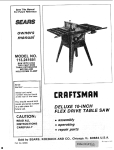
Model No. 831.297541
Serial No.
The serial number can be found in
the location shown below. Write the
serial number in the space above.
Serial Number Decal
_kCAUTION!:
Read all safety prec,_utions and
instructions in this manual
before using this equipment.
Keep this manual in a safe place
for future reference.
OWNER'S MANUAL
I
FULL 90 DAY WARRANTY
For 90 days from the date of purchase, when proper assembly and maintenance procedures detailed in
the Owner's Manual are followed, SEARS will, free of charge, repair or replace and install a replacement
part for any defective part, when this treadmill is used in a normal manner.
This warranty does not apply when this treadmill is used for commercial or rental purposes.
SERVICE IS AVAILABLE SIMPLY BY CONTACTING YOUR NEAREST SEARS SERVICE CENTERJDEPARTMENT IN THE UNITED STATES.
This warranty gives you specific legal rights, and you may also have other rights which vary from state
to state.
SEARS; ROEBUCK AND CO., DEPT. 817WA,
HOFFMAN ESTATES, IL 60179
2
LS
ehte
0-8 mph ° 2.0 hp • direct pulse interface ° fat burn guide
TABLE OF CONTENTS
IMPORTANT SAFETY PRECAUTIONS .........................................................
BEFORE YOU BEGIN .......................................................................
ASSEMBLY ..........
.....................................................................
HOW TO USE THE PULSE SENSOR ..........................................................
OPERATION AND ADJUSTMENT
.............................................................
TROUBLE-SHOOTING
AND STORAGE ........................................................
CONDITIONING GUIDELINES ...............................................................
PART LIST ...............................................................................
EXPLODED DRAWING .....................................................................
ORDERING REPLACEMENT PARTS .................................................
_kWAR NING:
4
5
6
8
9
14
16
18
19
Back Cover
Before beginning this or any exercise program, consult your physician.
This is especially important for persons over the age of 35 or persons with pre-existing health problems.
Read all instructions before using. SEARS assumes no responsibility for personal injury or property
damage sustained by or through the use of this product.
3
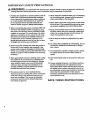
IMPORTANT
SAFETY PRECAUTIONS
WARN I NG:
To reduce the risk of burns, fire, electric shock or injury to persons, read the fol-
lowing important safety precautions and information before operating the treadmill.
Position the treadmill on a level surface, with at
least 8 feet of clearance behind the treadmill.
Do not place the treadmill near water, outdoors
or on any surface that blocks an air opening.
Do not operate where aerosol products are
used or where oxygen is being administered.
.
When connecting the power cord (see HOW TO
PLUG IN THE POWER CORD on page 9), plug
the power cord directly into a grounded circuit
capable of carrying 12 or more amps. No other
appliance should be on the same circuit. Keep
the power cord away from heated surfaces, if
an extension cord is needed, use only a 14gauge general-purpose cord of five feet or less
in length with a three-wire conductor.
3. Never move the walking belt while the power is
turned off. Do not operate the treadmill if the
power cord or plug is damaged, or if the treadmill is not working properly. (See BEFORE YOU
BEGIN on page 5 if the treadmill is not working
properly.)
4. Wear appropriate exercise clothing when using
the treadmill; do not wear loose clothing that
could become caught in the treadmill. Always
wear athletic shoes; never use the treadmill
with bare feet, wearing only Stockings or in
sandals. Athletic support clothes are recommended for both men and women.
5.
4
The pulse sensor is not a medical device.
Various factors, including the user's movement
while exercising, may affect the accuracy of
heart rate readings. The sensor is intended
only as an exercise aid in determining heart
rate trends in general.
6. Never start the treadmill while you are standing
on the walking belt. Always hold the handrail
when exercising on the treadmill.
7. Never allow more than one person on the treadmill at a time. The treadmill should not be used
by persons weighing more than 250 pounds.
8. Keep small children away from the treadmill at
all times. Never leave the treadmill unattended
while it is running. Always turn the power off
when the treadmill is not in use.
9. Never drop or insert any object into any opening.
10. To reduce the possibility of overheating, do not
operate the treadmill continuously for longer
than 1 hour.
11. The treadmill is capable of high speeds. Adjust
the speed slowly to avoid sudden jumps in
speed.
12. Use the treadmill only as described in this manual.
13. Always unplug the power cord before performing the maintenance and adjustment procedures described in this manual. Neyer remove
the safety cover unless instructed to do so by
an authorized service representative. Servicing
other than the procedures in this manual
should be performed by an authorized service
representative only.
SAVE THESE INSTRUCTIONS
BEFORE YOU BEGIN
Thank you for selecting the SEARS LS ELITE 780
treadmill. The LS ELITE 780 treadmill blends
advanced technology with innovative design to let you
enjoy an excellent form of cardiovascular exercise in
the convenience and privacy of your home.
For your safety and benefit, read this manual carefully before using the treadmill; if you have additional questions, please call our Customer Sewice
Department toll-free at 1-800-999-3756, Monday
through Friday, 6 a.m. until 6 p.m. Mountain Time
(excluding holidays). To,help us assist you, please
note the product model number and sedal number
before calling. The model number of the treadmill is
831.297541. The serial number can.be found on a
decal attached to the treadmill (see.the front cover of
this manual for the location).
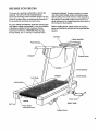
Before reading further, please review the drawing
below and familiarize yourself with the parts that are
labeled.
Console
\
Key/Clip
Handrai
Console Knob
Uprights
Circuit Breaker
FRONT
On/Off Switch
Foot Rails
Walking Belt
Power Cord
BACK
RIGHT SIDE
Belt Tool
Rear Roller
Adjustment Bolt
Cushion Knob
5
ASSEMBLY
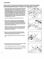
Assembly requires the assistance Of a second person. Set the treadmill in a cleared area and remove all
packing materials. Do not dispose of the packing materials until assembly is completed. THE FOLLOWING
TOOLS ARE REQUIRED FOR ASSEMBLY: An adjustable wrench _
1.
(not included).
Find the Right Updght (15) (see the inset drawing to identify the
Right Updght). Insert a 3/8" x 3 1/2" Bolt (27), with one of the
four Upright Washers (26), into the higher hole in the bottom of
the Right Upright. Slide one of the two Star Washers (107) onto
the Bolt. Finger tighten the Bolt into the indicated hole in the
side of the Frame (50). Hold an Upright Spacer (48) inside the
bottom of the Right Upright. Insert a 3/8" x 3 1/2" Bolt (27), with
an Updght Washer (26), through the lower hole in the bottom of
the Right Upright and the Spacer. Finger tighten the Bolt into
the indicated hole in the Frame.
Attach the Left Upright (not shown) in the same manner.
2.
Hold the Console Crossbar (6) near the Right Upright (15).
Connect the Console Wire Harness (10) to the Updght Wire
Harness (12). The small latch on the Console Wire Harness
should snap onto the Upright Wire Harness (see the inset drawing). If the Wire Harnesses do not fit easily, turn them; do not
force the Wire Harnesses together.
6
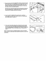
Adjust the 24" Cable Loom (11) and6" Cable Loom (30) so that
the ends of the Wire Hamesses (10, 12) are covered. Insert the
Cable Looms into the Right Updght (15). Be careful not to
damage the Wire Harnesses.
3.
Slide the Console Crossbar (6) into the Right Upright (15).
Rotate the Console Crossbar to the desired angle. Tighten a
Console Knob (3) into the Console Crossbar.
11 12
3O
3
4
15
3
Push an Upright Endcap (4) into the end of the Right Upright
(15).
4. Slide the Console Crossbar (6) into the Left Upright (2). Tighten
a Console Knob (3) into the Console Crossbar.
4
3
Push an Upright Endcap (4) into the end of the Left Upright (2).
Using an adjustable wrench, tighten the four 3/8" x 3 1/2" Bolts
(27) used in assembly step 1 (see assembly step 1).
6
4
5. Plugthe lower end
of the Upright Wire Hamess (:t2) into the 20"
Wire Hamess (45). The small latch on the Upright Wire Harness
should snap onto the 20" Wire Harness (see the upper inset
drawing). If the Wire Harnesses do not fit easily, turn them; do
not force the Wire Harnesses together.
Slide the ends of the two 6" Cable Looms (30) against the ends of
the Wire Harnesses (45, 12) (s.ee the lower inset drawing). Be
careful not to damage the Wire Harnesses.
12
6. Press the Belt Tool (86) into the opening in the Left Rear
Endcap (82). The Belt Tool is used to center the Walking Belt
(see SYMPTOM 6 on page 14).
86
7. Press open the Clothes Clip (14), and insert the pulse earclip
wire into the Clothes Clip. Make sure that the pulse earclip
wire is resting against the hinge of the Clothes Clip (see the
inset drawing). The use of the pulse sensor is explained on
page 8.
7
Pulse Earclip Wire
14
Make sure that all parts are tightened before using the treadmill.
Note: The floor underneath the treadmill should be covered for
protection.
7
HOW
TO USE THE PULSE SENSOR
The treadmill features a unique headband-style pulse
sensor. The rubber-armored pulse sensor and lightweight headband are specially designed for greater
accuracy, comfort and durability. To get the best performance from the pulse sensor, please read the
following instructions.
To learn how to use the pulse sensor with the console,
see HOW TO USE THE PULSE DISPLAY on page 11.
To ensure the best results, remember the following
important guidelines:
How
•
Before putting on the headband, rub your forehead
for a moment to stimulate circulation.
"
•
Make sure that the headband is properly adjusted. If
the headband is too tight or too loose, your pulse
may not be detected.
TO ADJUST THE HEADBAND
In order for the pulse sensor to function, the headband
must be properly adjusted. The headband should fit
snugly around your head, without being uncomfortable.
To adjust the headband, slip it oft the adjustment tab
on the pulse sensor. Insert the adjustment tab through
a different hole in the headband.
HOW TO OBTAIN ACCURATE PULSE READINGS
The headband must be worn properly--the sensor
window should be centered on your forehead, and
there should be no hair between the sensor window
and your forehead. Make-up applied to the forehead
may also interfere with pulse readings.
Note: If the pulse sensor does not function when the
sensor window is centered on your forehead, try
positioning the sensor window over your right or left
eyebrow. Depending on the shape of your forehead,
it may be easier to detect your pulse from a slightly
different position.
Make sure that the pulse sensor wire is fully
plugged intothe jack on the console,
HOW TO PUT ON THE PULSESENSOR
Rub your forehead for a moment to stimulate circulation. Put on the headband as shown below, with the
sensor window centered on your forehead. Make sure
that there is no hair between the sensor window and
your forehead. IMPORTANT: To avoid static buildup, the pulse sensor should be worn only while
you are standing on the treadmill.
Attach to the pulse sensor wire to your collar with the
clothes clip. The clip will minimize movement of the
wire, helping to ensure accurate pulse readings.
Sensor
•
Avoid excessive head movement during exemise.
Clean the sensor window about once each week
when the treadmill is used regularly. Using a cotton
swab moistened with water, carefully wipe the sensor window.
Because your pulse constantly changes, the pulse
sensor will sample and average your pulse every
few seconds. When you first put on the pulse sensor, it may be necessary to wait for up to ten seconds before an accurate pulse is shown.
HOW
TO CLEAN THE PULSE SENSOR
To clean the headband, first remove it from the pulse
sensor. Hand wash the headband in mild detergent,
and gently wring it out.
The pulse sensor can be wiped clean with a damp
cloth; never immerse the pulse sensor in water.
B
/
OPERATION
MAINTENANCE-FREE
AND ADJUSTMENT
WALKING
BELT
Your treadmill features a maintenance-free walking
belt coated with PERFORMANT LUBE TM, a highperformance lubricant. Dudng the first few hours of
use, it is normal for a small amount of white powder to
appear on the foot rails and the walking platform. The
white powder is high-performance lubricant from the
walking belt.
IMPORTANT: Never apply silicone spray or other
substances to the walking belt or the walking platform. They will deteriorate the walking belt and
cause excessive wear.
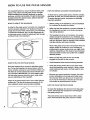
HOW TO ADJUST THE CUSHION LEVELOF THE LEGS
The legs at the back of the treadmill are designed to
absorb shock as you walk or run on the treadmill. The
cushion level of the legs can be adjusted to the level
that is the most comfortable for you.
For a softer cushion level, turn the cushion knob counterclockwise (see the drawing below). For a firmer
cushion level, turn the knob clockwise. Note: The
faster you run on the treadmill, the firmer the cushion
level should be. If the cushion level is too soft, the
treadmill will bounce excessively.
electric shock. Check With a qualified electrician or serviceman if you are in doubt as to whether the product
is propedy grounded. Do not modify the plug provided
with the product---if it will not fit the outlet, have a proper outlet installed by a qualified electrician.
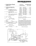
This product is for use on a nominal 120-volt circuit,
and has a grounding plug that looks like the plug illustrated in Drawing I below.
A temporary adapter that looks like the adapter illustrated in Drawing 2 may be used to connect this plug
to a 2-pole receptacle as shown in Drawing 2 if a
propedy gr:ounded outlet is not available. The temporary adapter should be used only until a properly
grounded 6utlet (Drawing 1) can be installed by a qualified electrician. The green colored rigid ear, lug, or the
like extending from the adapter must be connected to
a permanent ground such as a properly grounded outlet box cover. Whenever the adapter is used it must
be held in place by a metal screw.
Some 2-pole receptacle outlet box covers are not
grounded. Contact a qualified electrician to determine if the outlet box cover is grounded before
using an adapter.
1
Grounded
Grounding Plug
Knob
Grounding Pin
Grounded Outlet
HOWTO
PLUG IN THE POWER CORD
This product must be grounded. If it should malfunction or break down, grounding provides a path of least
resistance for electric current to reducethe risk of electric shock,
This product is equipped with a cord having an equipment-grounding conductor and a grounding plug. Plug
the power cord into an appropriate outlet that Is
properly installed and grounded in accordance
with all local codes and ordinances.
DANG ER:
equipment-grounding
Improper
connection
ofthe
conductor can result in a risk of
2
J
Grounded
Outlet Box
Adapter
rounding Pin
Grounding
Met_a,Screw_q'---3__
9
o
(
C
o
D
[
THE INTERACTIVE CONSOLE
The heart of the treadmill is the state-of-the-art interactive console. The console offers electrpnic speed and
incline control, six independent displays, and a Fitness
Test that measures your relative fitness level. In addition, a unique Fat Calorie Monitor is built into the console. During exercise, your body burns either fat calories or carbohydrate calories, depending on the intensity of your exercise. If your goal is to bum fat, it is
essential that you exercise at the proper intensity level.
The Fat Calorie Monitor will constantly monitor your
workout, and show you when your intensity level is too
low, too high or perfect for burning fat. CAREFULLY
READ THESE INSTRUCTIONS BEFORE OPERATING THE CONSOLE. Note: If there is a thin sheet of
clear plastic on the face of the console, peel it off
before operating the console.
HOW TO ADJUST THE ANGLE OF THE CONSOLE
The angle of the console can be
adjusted for easy
viewing. First,
loosen the knob on
each side of the
console. Rotate
the console to the
desired angle and
retighten the
knobs.
Console
kWARNING:
oo not stand on the walk-
ing belt when turning on the power or starting the
walking bell Always wear the clip while operating
the treadmill.
Insert the safety key into the console. The "NO PULSE
DETECTED" indicator, the MANUAL CONTROL indicator, and the six displays will light. The PULSE display will flash the current age setting three times, and
the CALORIES display will flash the current weight setting three times. (If age and weight settings have never
been entered into the console, the PULSE display will
flash the letters "AGE" three times, and the CALORIES
display will flash the letters "LBS" (pounds) three times.
ENTER YOUR AGE AND WEIGHT
For the console to measure calories accurately, and
for the Fat Calorie Monitor and the Fitness Test to
function properly, your age and weight must be
entered into the console.
Make sure that the
10
Stand on the foot rails of the treadmill. Find the clip
attached to the safety key, and slide the clip onto the
waistband of your clothing.
HOWTO
HOW TO TURN ON THE POWER
safety key is
removed from the
console, and that
the on/off switch
is in the console when the power cord is plugged in,
the letters "PC)"will flash in the SPEED display, ff this
occurs, simply remove the safety key.
Position
"On"
near the power
cord is in the =on"
position. Plug in the power cord (see HOW TO PLUG
IN THE POWER CORD on page 9). All displays and
indicators will flash three times. Note: ff the safety key
To enter your age, press one of the AGE SET buttons.
The current age setting will be shown in the PULSE
display. Press the AGE SET buttons to enter your age.
Each time one of the buttons is pressed, the age setting will change by I year. If the buttons are held
down, the age setting will change in increments of 5
years. After you have entered your age, press one of
the WEIGHT SET buttons. The current weight setting
will be shown in the CALORIES display. Press the
WEIGHT SET buttons to enter you weight. Each time
one of the buttons is pressed, the weight setting will
change by 1 pound. If the buttons are held down, the
weight setting will change in increments of 5 pounds.
Once you have entered your age and weight, the num-
bers will be retained in the console's memory, even if
the power cord is unplugged. The numbers can be
changed, if desired, by pressing the AGE SET or
WEIGHT SET buttons.
HOW
TO MANUALLY
CONTROL
THE SPEED
When the power is turned on, the console will be in the
MANUAL CONTROL mode. For your safety, the walking belt will be stationary. The speed range of the
walking belt is 0.5 to 8 miles per hour.The speed is
controlled with the SPEED buttons. Each time the
INCREASE SPEED button is pressed, the speed will
increase by 0.1 mph. Each time the DECREASE
SPEED button is pressed, the speed will decrease by
0.1 mph. The buttons can be held down to change the
speed rapidly.
WAR NING: After
theSPEED
buttons
are pressed, it will take a moment for the walking
belt to reach the selected speed setting. Adjust the
speed gradually until you are familiar with the
treadmill.
After a few seconds, the heart-shapedpulse indicator
will flash each time your heart beats, the "NO PULSE
DETECTED" indicator will darken, and your pulse will
be shown. Note: Because your pulse constantly
changes, the pulse sensdr will measure and average
your pulse every few seconds. When you first put on
the pulse sensor, it may take several seconds before
an accurate pulse is displayed. If your pulse is not
shown, see HOW TO OBTAIN ACCURATE PULSE
READINGS on page 8.
HOW TO USE THE CALORIES DISPLAY
For the CALORIES display to be accurate, your age
and weight must be entered into the console. If your
age and weight have not been entered, see HOW TO
ENTER YOUR AGE AND WEIGHT on page 10. The
CALORIES display will show the total number of calories that you have burned. To find the number of fat
calories that you have burned, press the TOTAL FAT
CALORIES button. The number of fat calories that you
have burned wil! be shown for three seconds.
INCLINE
Press the INCREASE SPEED button until the walking
belt begins to move at slow speed. Hold the handrails,
step carefully onto the walking belt, and begin exercising. Change the speed as desired by pressing the
SPEED buttons. To stop the walking belt, press the
STOP button.
HOW
TO MANUALLY
CONTROL
THE INCLINE
To vary the intensity of your exercise, the incline of the
treadmill can be changed. The incline range of the
treadmill is 1% to 12%. The incline is controlled with
the INCLINE buttons. Each time one of the buttons is
pressed, the incline will change by 0.5%. The buttons
can be held down to change the incline rapidly. Note:
Because the INCLINE display has two digits, the display will show 10% wSen the incline is set at either
10% or 10.5%, and 11% when the incline is set at
either 11% or 11.5%.
Note: After the INCLINE buttons are pressed, it will
take a few seconds for the treadmill to reach the
selected incline setting.
HOW TO USE THE PULSE DISPLAY
To measure your
pulse, first put on the
pulse sensor (see
HOW TO USE THE
PULSE SENSOR on
page 8). Plug the
pulse sensor wire
into the jack on the
front of the console.
DISPLAY OPERATION
The INCLINE display will show the incline level that
has been selected.
SPEEDDISPLAY OPERATION
The SPEED display will show the speed Setting that
has been selected.
TIME DISPLAY OPERATION
The TIME display will show the total time that the walking belt has been moving. Note: If the Fitness Test is
selected, the display will be reset to zero. The display
will be reset again when the Fitness Test is completed.
DISTANCE
D!SPLAY OPERATION
The DISTANCE display will show the total distance
that you have walked or ran, in miles. Note: If the
Fitness Test is selected, the display will be reset to
zero. The display will be reset again when the Fitness
Test is completed.
HOW TO USE THE FAT CALORIE
MONITOR
The Fat Calorie Monitor is designed to help you maintain the proper workout intensity level for burning fat.
For the Fat Calorie Monitor to operate properly, your
age and weight must be entered into the console. If
your age and weight have not been entered, see HOW
TO ENTER YOUR AGE AND WEIGHT on page 10. In
addition, the pulse sensor must be used (see HOW TO
USE THE PULSE DISPLAY on this page).
11
When the Fat
Calorie Monitor is
activated, one of
wooden
_E.sr_ m__u.._; tAT
the five indicators
_wO O(_O
O
in the center of the
console will light.
The two red indicators on the left indicate that your intensity level is too
low for burning fat effectively. The two red indicators
on the dght indicate that your intensity level is too high
for burning fat effectively. When your intensity level is
perfect for buming fat, the green indicator in the center
will light. As you exercise, simply adjust the speed of
the walking belt and the incline of the treadmill so that
the green indicator remains lit. NOTE: After adjusting
the speed or incline, wait for about two minutes for
your pulse to respond before adjusting the speed or
incline again.
HOW TO USE THE FITNESSTEST
The Fitness Test is designed to measure your relative
fitness level. For the best results, the Fitness Test
should be taken at a time of day when your energy
level is high. The Fitness Test should not be taken
after you have already exercised dudng the day.
The Fitness Test consists of seven 3-minute segments. The console will automatically controlthe
incline of the treadmill and the speed of the walking
belt during the Fitness Test. During the first segment,
the incline will be at 2%, and the speed will be at 1.5
mph; at the beginning of the second segment, the
incline will increase to 3%, and the speed will increase
to 2.5 mph; at the beginning of the third segment, the
speed will increase to 3.3 mph; at the beginning of the
fourth segment, the incline will increase to 6%; at the
beginning of the fifth segment, the incline will increase
to 9%; at the beginning of the sixth segment, the
incline will increase to 12%; at the beginning of the
seventh segment, the speed will increase to 4 mph.
Follow the instructions below to use the Fitness Test.
Test is selected, only the STOP and MANUAL MODE
buttons will function.
2. PUT ON THE PULSESEN_;OR
See HOW TO USE THE PULSE DISPLAY on page
11. If your pulse is not detected, the letters =PLS" will
flash in the PULSE display.
3. PRESSTHE FITNESS TESTBunON
To start the Fitness Test, standon the foot rails of the
treadmill and press the FITNESS TEST button: The
first segmeht of the Fitness Test will begin, and the
walking belt will begin to move at 1.5 mph. Step onto
the walking belt and begin exercising. After three minutes, the second segment will begin=the incline will
increase to 3%, and the speed will increase to 2.5
mph. The Fitness Test will continue in this manner "until
your pulse reaches 70% of your maximum heart rate,
and the current segment is completed. The walking belt
will then slow to a stop, and the Fitness Test will be
completed, regardless of how many segments remain.
Your fitness level will be shown in the TIME display.
There are ten fitness levels--fitness level t (FL 1) is
the lowest, and fitness level 10 (FL10) is the highest.
Remember, the Fitness Test is intended only to indicate your relative fitness level, and to show your
progress over a period of time.
If your pulse is not detected during the last thirty seconds of any segment, the walking belt will slow to a
stop and the TIME display will show =FL 0," indicating
that an error has occurred. If you wish to stop the walking belt while the Fitness Test is in progress, press the
STOP button. The console will then be in the MANUAL
CONTROL mode.
HOW TO TURN OFF THE POWER
To turn off the power, remove the safety key from the
console. All indicators and LED displays will darken.
Store the safety key in a secure location.
1. PRESSTHE FITNESSTEST BUTI'ON
HOWTO
When the FITNESS TEST button is pressed, the
PULSE display will flash the current age setting three
times, and the CALORIES display will flash the current
weight setting three times. For the Fitness Test to
operate properly, your age and weight must be entered
into the console. If your age and weight have not been
entered, see HOW TO ENTER YOUR AGE AND
WEIGHT on page 10.
12
When the Fitness Test button is pressed, the INCLINE
display will show that the treadmill is at an incline level
Of 2%. The CALORIES, SPEED, TIME and DISTANCE
displays will be reset to zero. Note: While the Fitness
SELECTTHE INFORMATION
MODE
The console features an information mode that keeps
track of tdp time and distance, as well as the total time
and distance that the treadmill has been operated. To
select the information mode, hold down the STOP button while inserting the safety key into the console.
The SPEED display will show the letter "T," indicating
that trip time and distance are shown. The trip time will
be shown in the TIME display. The tdp distance will be
shown in the DISTANCE display. The trip time and distance can be reset to zero, if desired, by pressing the
WEIGHT SET DECREASE button.
Toviewtotaltimeanddistance,pressthe FITNESS
TESTbutton.Theletter"T"in the SPEED display will
darken. The total time will be shown in the TIME display, up to 9,999 hours.The total distance will be
shown in the DISTANCE display, up to 999 miles (if
the total distance exceeds 999 miles, the display will
begin again at zero). The total time and distance cannot be reset to zero.
To exit the information mode, remove the safety key.
13
TROUBLE-SHOOTING
AND STORAGE
Most treadmill problems can be solved by following the simple steps below. Find the symptom that applies,
and follow the steps listed. If further assistance is needed, call our Customer Service Department toll-free at 1800-999-3756, Monday through Friday, 6 a.m. until 6 p.m. Mountain Time.
1. SYMPTOM:
THE POWER DOES NOTTURN
ON
a. Make sure that the power cord is plugged into a properly grounded outlet. (See HOW TO PLUG IN THE
POWER CORD on page 9.) If an extension cord is needed, use only a 14-gauge general-purpose cord of
five feet or less in length.
b. After the power cord has been plugged in, make sure that the safety key is fully ihserted into the console.
Various indicators on the console should light. (See HOW TO TURN ON THE POWER on page 10.)
c. Check the circuit breaker located on the treadmill near the
power cord. If the switch protrudes as shown, the circuit
breaker has tripped. To reset the circuit breaker, wait for five
minutes and then press the switch back in.
Tripped
_
Reset
d. Check the On/Off switch located at the front of the treadmill
On
near the power cord. The switch must be in the On position.
Position
2. SYMPTOM: THE POWER TURNS OFF DURING USE
a. Check the circuit breaker located on the treadmill near the power cord. If the circuit breaker has tripped (see
the drawing above.), wait for five minutes and then press the switch back in.
b. Make sure that the power cord'is plugged in.
c. Remove the safety key from the console. Reinsert the safety key fully into the console. Various indicators on
the console should light.
d. Check to make sure the On/Off switch is in the On position. (See 1. d. above.)
e. If the treadmill still will not run, please call our Customer Service Department.
3. SYMPTOM:
THE PULSE SENSOR DOES NOT FUNCTION
PROPERLY
a. See HOW TO USE THE PULSE SENSOR on page 8.
4. SYMPTOM:
THE CONSOLE
DOES NOT FUNCTION
PROPERLY
a. If a console malfunction occurs, an error code ("El ," "E2," "E3," etc.) may appear on the display. If an error code
appears, remove the safety key, wait for ten seconds and then reinsert the safety key. If an error code appears
again, call our Customer Service Department. Do not operate the treadmill until the problem is corrected.
5. SYMPTOM:
THE WALKING
BELT SLOWS WHEN
WALKED ON
a. If an extension cord is needed, use only a 14-gauge general-purpose cord of f'we feet or less in length.
b. If the walking belt still slows when walked on, please call our Customer Service Department.
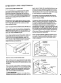
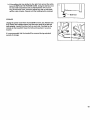
6. SYMPTOM: THE WALKING BELT IS OFF-CENTER WHEN WALKED ON
a. If the walking belt has shifted to the left, first remove the safety
key and UNPLUG THE POWER CORD. Using the belt tool,
turn the rear roller adjustment bolt clockwise 1/4 of a turn. Plug
in the power cord, insert the safety key and run the treadmill
for a few minutes. Repeat until the walking belt is centered.
14
a
_
k
Belt Tool
b. If the walking belt has shifted to the dght, first remove the safety
ke_, and UNPLUG THE POWER CORD. Using the belt tool, turn
the rear roller adjustment bolt counterclockwise 1/4 of a turn.
Plug in the power cord, insert the safety key and run the treadmill for a few minutes. Repeat until the walking belt is centered.
b
_BeltTool
_
I
STORAGE
Unplug the power cord when the treadmill is not in use. Remove one
bolt, washer and upright spacer from the lower ends of the left and
right updghts. Loosen the other bolt on each side. Carefully lay the
console on the treadmill. Keep the bolts and Washers in a secure
Iocat;on.
It is recommended that the treadmill be covered during extf_nded
periods of storage.
15
CONDITIONING
GUIDELINES
The following guidelines will help you to plan your
exercise program. Remember that proper nutrition and
adequate rest are essential for successful results.
, WARNING:
Before beginning this or
any exercise program, consult your physician.
This is especially important for individuals over
the age of 35 or individuals with pre-existing health
problems.
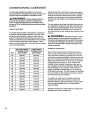
EXERCISEINTENSITY
To maximize the benefiis of exercising, it is important
to exercise with the proper intensity. The proper intensity level can be found by using your heart rate as a
guide. For effective aerobic exercise, your heart rate
should be maintained at a level between 70% and 85%
of your maximum heart rate as you exercise. This is
known as your training zone. You can find your training
zone in the table below.
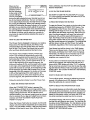
16
CONDITIONED
TRAINING ZONE
AGE
UNCONDITIONED
TRAINING ZONE
(BEATS/MIN
29
138-167
"133-162
25
136-166
132-160
30
135-164
130-158
35
134-162
129-156
40
132-161
127-155
45
131-159
125-153
50
129-156
124-150
55
127-165
122-149
60
126-153
121-147
65
125-151
119-145
70
123-150
118-144
75
122-147
117-142
80
120-146
115-140
85
118-144
114-139
(BEATS/MIN
During the first few months oi your exercise program,
keep your heart rate near the low end of your training
zone as you exercise. After a few months of regular
exercise, your heart rate can be increased gradually
until it is near the middle of your training zone as you
exercise.
You can measure your heart rate using the pulse sensor. Exercise for at least four minutes, and then measure your heart rate immediately. If your heart rate is
too high, decrease the intensity of your exercise. If
your heart rate is too low, increase the intensity of your
exercise.
WARNING:
The pulse sensor is not:a
medical device. Various factors, including your
movement during exercise, may affect the accuracy of heart rate readings. The sensor is intended
only as an exercise aid in determining heart rate
trends in general.
WORKOUT GUIDELINES
Each workout should consist of three basic pads: a
warm-up, 20 to 30 minutes of training zone exercise,
and a cool-down. Warming up prepares the body for
exercise by increasing circulation, delivering more oxygen to the muscles and raising the body temperature.
Begin each workout with 5 to 10 minutes of stretching
and light exercise to warm up. Then, increase the
intensity of your exercise to raise your heart rate to
your training zone for 20 to 30 minutes. Breathe regularly and deeply as you exemise--never hold your
breath. Finish each workout with 5 to 10 minutes of
stretching to cool down. This will increase the flexibility
of your muscles as well as help to decrease soreness
and other post-exercise problems.
To maintain or improve your condition, plan three
workouts each week, with at least one day of rest
between workouts. After a few months of regular exercise, you may complete up to five workouts each
week, if desired.
The key to success is to make exercise a regular and
enjoyable part of your everyday life.
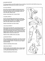
SUGGESTED STRETCHES
The following stretches can provide a good warm-up or cool-down. Correct form for each stretch is shown in the
drawings below. Move slowly as you stretch---never
bounce.
TOE TOUCH STRETCH
Stand with your knees bent slightly and slowly bend forward
from your hips. Allow your back and shoulders to relax as you
reach down toward your toes as far as possible. Hold for 15
counts, then relax. Repeat 3 times.
Stret'ches: Hamstrings, back of knees and back.
HAMSTRING
STRETCH
Sit with one leg extended. Bring the sole of the opposite foot
toward you and rest it against the inner thigh of your extended
leg. Reach toward your toes as far as possible. Hold for 15
counts, then relax. Repeat 3 times for both legs.
Stretches: Hamstrings, lower back and groin.
CALF/ACHILLES
STRETCH
With one leg in front of the other, reach forward and place your
hands against a wall. Keep your back leg straight and your
back foot flat on the floor. Bend your front leg, lean forward and
move your hips toward the wall. Hold for 15 counts, then relax.
Repeat 3 times for both legs. To cause further stretching of the
achilles tendons, bend your back leg as well.
Stretches: Calves, achilles tendons and ankles.
QUADRICEPS STRETCH
With one hand against a wall for balance, reach back and grasp
one foot with your other hand, Bring your heel as close to your
buttocks as possible. Hold for 1"5counts, then relax. Repeat 3
times for both legs.
Stretches: Quadriceps and hip muscles.
INNER THIGH STRETCH
Sit with the soles of your feet together and your knees outward.
Pull your feet toward your groin area as far as possible. Hold
for 15 counts, then relax. Repeat 3 times.
Stretches: Quadriceps and hip muscles.
17
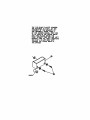
THr" Tvn 3t.ACY, PLASTXC _PAC_RS
ARE:REOUIRE9 I)[ _'rE;P 1 gF" THE
ASSEI43LY Dr THE UPPJE'HT$TD
Trl£ TRFJ_HILL FRAH_ PAC_ 6
DF TI_ O_l_
HANU/_ _
ARE
TO BE _
_N THE LDVER HOLES
DNLY _
PL/_"E] INSZl]IE THE;
RIrgtT UPRmHT TUBE €3:D AND LEFT
UPRIGHT _
(2), VHZLI_.XI'ZSERTZHG
THE 3/8" X 3-1/2" )DLT (27)
THROUGHTH/_ LDVIER HOLES & "
THE _;PACE:R.
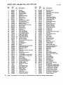
PART LIST--Model
18
Key
No.
Part
No.
Qty.
1
2
3
4
5
6
7
8
9
10
11
12
t3
14
15
16
17
18
19
20
21
22
23
24
25
26
27
28
29
30
31
32
33
34
35
36
37
38
39
40
41
42
43
44
45
46
47
48
49
50
51
52
53
54
55
56
57
58
120554
120202
120244
120248
111869
120203
120489
013141
120769
120552
117988
123086
119038
121078
120239
031229
109382
019084
119163
t 19014
120774
112609
014127
119015
013162
014132
120003
120311
115468
113203
117806
108080
120243
123308
107503
119026
012056
120767
119416
052014
013547
012149
119020
120729
119769
015071
121728
122332
014157
NSP
120195
123366
120491
122945
120241
122329
120242
120492
2
1
2
2
6
1
1
7
1
1
1
1
1
1
1
1
1
1
1
1
1
1
5
1
23
4
4
1
2
2
2
8
1
1
1
1
6
1
1
2
3
5
1
1
1
4
2
2
t
1
1
1
1
t
1
2
t
1
No. 831.297541
Description
I:ndcap
Left Upright
Console Knob
Upright Endcap
Cage Nut
Console Crossbar
Wire Cover
Console Screw
Console
(_onsole Wire Harness
24" Cable Loom
Upright Wire Harness
Safety Key/Clip
Pulse Sensor/Clothes Clip
Right Upright
Power Cord
Circuit Breaker
Grommet
On/Off Switch
Front Left Endcap
Front Roller/Pulley
Front Roller Adj. Bolt
Roller Adj. Washer
Front Right Endcap
Safety Cover Screw
Upright Washer
3/8" x 3 1/2" Bolt
Power Board-Controller Wire
Belt Guide
6" Cable Loom
Wheel Bolt
Screw
Right Rear Belt Tension Bolt
Electronics Bracket
Motor Swivel Bolt
Bracket
Wheel Nut/Cushion Foot Nut
Controller
Safety Cover Bracket
Front Wheel
Leg Bolt/Motor Tension Bolt
Leg Nut/Motor Tension Nut
incline Leg
Power Board
20" Wire Harness
Power Board Stand-Off
Cushion Foot Cover
Updght Spacer
Switch Star Washer
Frame
Front Safety Cover
Rear Safety Cover
Right Foot Rail
Walking Belt
Adj. Bolt Guide
Deck Shim
Belt Tension Spdng
Cushion Foot Rod
" Key
No.
59
60
61
62
63
64
65
66
67
68
89
70
71
72
73
74
75
76
77
78
79
80
81
82
83
84
85
86
87
88
89
90
91
92
93
94
95
96
97
98
99
100
101
102
103
104
105
106
107
#
#
#
#
#
#
#
#
#
Rt 94A
P&rt
No.
Qty.
013028
012096
102633
102959
102955
012152
109370
116892
119375
122116
114270
120481
120483
122202
110926
119017
115046
016029
016057
013206
116927
121204
119296
119016
120775
122205
119779
120844
120866
120482
122196
120867
122644
1 t 3278
106939
t 00994
120740
120197
120653
122125
105477
014086
121375
121617
122331
122926
104188
122812
014117
101799
107771
101897
109407
101951
102634
118201
112083
122133
6
1
2
2
2
2
1
1
2
1
1
1
2
2
4
1
2
2
5
1
1
4
1
1
1
1
8
1
5
1
1
1
t
1
1
2
1
1
1
1
2
2
1
1
2
1
2
1
2
1
1
1
1
1
1
1
1
1
Description
Endcap Screw
Spring Nut
Optic Switch Wire Harness
Small Bolt
Optic Switch
Small Nut
incline Optic Switch
incline Motor Bracket
incline Motor Bolt
Incline Motor
incline Motor Spacer
Bar Endcap
Cushion Foot Insert
Foot Rail Bracket
Cushion Foot Bolt
Right Rear Endcap
Cushion Foot
4" Cable Tie
8" Cable Tie
Left Rear Belt Tension Bolt
Tie Block
Front Endcap Screw
Cable Tie
Left Endcap
Rear Roller
Walking Platform
Platform Screw
Belt Tool
Electronics Screw
Cushion Knob
Left Foot Rail
Motor Tension Nut
Motor Mounting Bracket
Pulley/Flywheel/Fan
Motor Belt
Motor Bolt
Motor
Speed Disk
Optic Switch Bracket
Optic Switch Bracket Nut
Motor Nut
Flat Washer
Red Headband
Video Cassette
Rod Sleeve
Blue Headband
Cover Washer
Motor Tension Washer
Star Washer
9" Black Wire, Male/Female
8" White Wire, Male/Female
14" White Wire, 2 Female
4" Black Wire, 2 Female
8" Black Wire, 2 Female
8" Green Ground Wire
8" Red Wire, Male/Female
8" Blue Wire, 2 Female
Owner's Manual
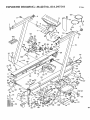
Note: "#" indicates a non-illustrated part. Specifications are subject to change without notice.
EXPLODED DRAWING--Model
No. 831.297541
Rl194A
lo1
9
2
5
6
14
4
104
30
93
102
94
8
3
11
10
95
42
97 64
91
61
27
16
35
17
41
89
70
48
56
84
23
86
54
/
52
.80
26
51
53
60
57
32
-34
82
78
23
42
44
39
38
36
87
75
37
100
25 59
88
19
ORDERING
REPLACEMENT PARTS
Each TREADMILL has its own MODEL NUMBER. Always mention this MODEL NUMBER when requesting service or repair parts for your TREADMILL.
All parts listed herein can be ordered through SEARS, ROEBUCK AND CO. SERVICE CENTERS and most
SEARS RETAIL STORES. If parts you need are not stocked locally, your order will be transmitted to a SEARS
PARTS DISTRIBUTION CENTER for handling.
WHEN ORDERING REPAIR PARTS, ALWAYS GIVE THE FOLLOWING INFORMATION:
• The MODEL NUMBER ofthe product (831.297541).
• The NAME of the product (SEARS LS ELITE 780 treadmill).
• The PART NUMBER of the part(s) from page 18 of this owner's manual.
• The DESCRIPTION of the part(s) from page 18 of this owner's manual.
Your SEARS TREADMILL has added value when you consider that SEARS has service units nationwide, staffed
with SEARS trained technicians specifically trained on SEARS products, having the pads, tools and equipment to
ensure that we meet our pledge to you: "We service what we sell."
Should you ever need repair service or parts, call toll free:
For repair service: 1-800-4-REPAIR
For repair parts: 1-800-FON-PART
(1-800-473-7247)
(1-800-366-7278)
Part No. 122133 R1194A Printed in USA
© 1994 Seam, Roebuck and Co.