1
91
OWNER'S
MANUAL
GAssembly
o Operation
° Customer Respensibilities
o Service and Adjustments
_,Repair Pa_s
CAUTION:
Read
and
follow
atl safety
ruses and
_nstructlons
before
operating
this
equipment.
SAFETY RULES
Safe Operation
Practices
iMPORTANT:
TH_S CUTTING MACHINE _S CAPABLE
OBJECTS,
FAILURE TO OBSERVE THE FOLLOWING
NJURY
l,
_,
_'
.
.
.
.
*,
_,
tL
OR DEATH
GENERAL
t[_L CHILDREN
OPERATION
and the mowing activity Nevetassume
were you last s_w them
C_ear the area ot objects such as recks, toys wire, etc.
which could be picked _:_pand thrown by the b_ade,
Be sure the area is ctear of other people before mewing Stop
mace Re if anyor_e enters the area
o
Never carry passengers.
Do r_otmow in _everse unless absolutely necessary Aways
took down and behind before and whiie backing.
Be aware of the mower discharge direction and do not point
}t at anyone. De not operate the mower without either the
eeti_e grass catche_ or the guard in piace.
SI@_ down before taming.
.
Never carry children
They may fali off and be sedously
iniured or ir'_tedere with safe machine operation.
Never allow children to operate the mace no,
Use extra care when approaching blind corners shrubs,
trees, or other objects that may ob_cure vision.
•
'_
Mow on_y in daylight or good a_t ficial lighL
Do not operate the machine whi_e under the influence of
alcohol or drugs
Watch for traffic when operating near or eros ing roadways_
Use extra care when loading or unloading the mace ne into
a trailer or truck.
Keep nu_s and bolts., especiaf_y binds attachment bolts, tight
and keep eq_iprnen_ in good condition
Never tamper with safety devices.
Check thor proper
SLOPE OPERATION
Keep machine free of grass teaves, or other debrs bu td_ap.
C!ean oi or tue_ spiI_age_ Allow machine to cod before
Mow up and down s_opes, not across
Remove obstacles such as rocks, tree limbs, etc.
Watch for hoIes, ruts or bumps. Uneven terrain could
ove_lurn the machine. Taft gr_:_sscan hide obstacle&
Use s_ow speed Choose a k_wgear so that you w ; not have
to atop or shift while on the slope.
Follow the manufacturers
recommendations
for whee_
weights or counterweights to reprove stability
_'
Keep all movement on the s;opes stow and graduat De not
make sudden changes ;r_speed or direction_
Avoid starling or stopping on a slope If tires lose traction,
disengage the Mades am:] proceed s_ow_ystraight down the
Stop and inspect the equ{pment if you strike an obiect.
Repair, f necessary, before resta£ing.
Never make adi_._stmerdsor repa rs wth the engne runnii'_g
Grass catcher components are subject to wear, damage, and
deterioration
which could expose moving pa_s or show
objects to be throws
Frequently check components arid
repines wth manufacturers r¢_ommended parts, when hoe
essaq/
Mower blades are sharp and carl euL Wrap the Made(s) or
wear g_oves, and use extra caution when serv;cieg them
Check brake operation freqaently.
Adjust and service as
Look for this symbof to point out important safety precautions,
It means
CAUTiON!i! BECOME ALERT!i! '/OUR
SAFETY IS INVOLVED,
Do net mow near drep..offs, ditches, or embankments
The
mower co_._ldsuddenly turn over if a whee_ is over the edge
of a cliff or ditch, or if an edge caves in.
Do net mow on wet grass Reduced traction could cause
CAUTION:
Always disconnect
spark
plug wire and place wire where it cannot
transporting,
Do not try to stabilize the machine by putting your foot on the
Do not use grass catcher on steep slopes.
and down for small
Use extra care in haedling gasoine and other fuels. They are
fiammable and vapors are exp!osive_
Use on_y an approved container
Never remove gas cap or add faei with the engine
ruenir g_ Allow engine to coo_ before iefue_ir_g. Do no!
smoke
Never _'efuel the machine indoors
Never tore the reacttins or rue! container nsde where
there is an open fin he, such as a water _eater
Never ren a machine inside a closed area
bdore dismounting
Turn off biades when not mowing_
Stop engine before removing grass catehe_ or unclogging
chute
DO NOT:
.
_oek behnd
SERVICE
,_
.
Keep children out of the mowing area and under the watchful
care of another responsible aci]_Jtt.
Be aie_ and turn machine off if ehildre_ enter he area
Before and when backing
cMIdren
DO_
,,
that children wfi remain
.
req_ire extra caution If you cannot back up the stops or if you fee_
uneasy on it, do not mow ii,
.
Mowers
OF AMPUTATING HANDS AND FEET AND THROWING
SAFETY INSTRUCTIONS COULD RESULT _N SERIOUS
Read, understand_ and foilow al_ instractio_s in the manua!
and on the machine before sta_ing.
Only alIow responsiMe adutts who are familiar with the
instructions, to operate the machine
*
for Ride-On
2
adjusting
or making
PRODUCT
tured to give you the best possble
dependabitty
150
and
tedDepa£ment
We have cor'npetent wetbtraned tech.,
nicians _nd the prape_ too_s to sewice or repair this unt
P_ease read and retain this manual, }he instructions wli
enable you to assemble and maintain your unit properly_
Atways observe the 'SAFETY RULES',
MODEL
NUMBER
SPECIFICATIONS
GASOLINE CAPAC TY
AND TYPE:
5 QUARTS
UNLEADED
O_L TYPE (AP/ SG}
SAE 30 above 32 '_ )
SAE 5W-30 (beow 32F}
eL
3.0 PNTS
CAPACITY:
SPARK PLUG:
(GAP:
030")
REGULAR
CHAMP}ON
RJ19LM
NTAKE:
EXHAUSTs
_005 -. 007'
.009
011 _
917,257590
SERIA{
NUMBER
DA'TE OF PURCHASE
THE MODELAND SERIAL NUMBERSW_LL BE FOUND
ON A PLATE UNDER THE SEAT
GROUND SPEED MPH>:
FORWARD:
REVERSE;
5.00
2.40
TIRE PRESSURE:
FRONT:
REARI
CHARGING SYSTEM:
3 AMPS BATTERY
5 AMPS HEADLtG qTS
BLADE BOLT TORQUE:
30-35 _sT'.LBS
14 PS}
12 PSI
YOU SHOULD RECORD BOTH SERIAL NUMBER AND
DATE OF PURCHASE AND KEEP iN A SAFE PLACE
FOR FUTURE REFERENCE_
MAINTENANCE
AGREEMENT
A Sears maintenance
agreement
uct. Cot tact your nearest Sears
CUSTOMER
s ava tabte on this prodstore fer deta Is.
RESPONSIBILITIES
Read and obsewe the safety rules.
Aathor zed Servce
fttrough yeur nearest Sears
"
(See REPAIR PARTS section of i'_s manua }.
Folow a regular schedule in maintainin 9, caring for and
using your unit.
Centel
Fo/ow the instructions unde_ 'Customer Responsibilities" and "Storage" sections of this owner's manua
L{M{TED TWO YEAR WARRANTY
ON ELECTRIC
START RIDING EQUIPMENT
For two (2) years from the date of purchase, if this riding equipment is maintained _ubiieated and tuned up accord nq ta the
instructions in the owners manual, Sears wil repair o rep/_ce free of ch_trge ary pa_ls found to be defective n matera_ or
This Warranty does not cover:
"
"
,_
,,
Expendable items which become warn during normal use, such as blades spa'k pl;gs air c_eaners and belts
Tie replacement or repair caused by punctures from outside obiects, such as hats, thorns stumps, or glass.
Repairs necessary because of operator abuse, negligence, improper .storage or accident or the faiure ta mair tan the
equipment accarding to the instructions conlained in the ewr_er's manua_
R}ding e%ipment used for commercial or rents} purposes
L{MITED 90 DAY WARRANTY
ON BAKERY
Far ninety (g0} days trom date of purchase, if any battery included with this riding equipment prowls defectiw:_ n materia_ or
workmanship and our testing determines the battery will not hold a charge, Sears will replace the batte_ at na charge.
WARRANTY SERVICE
CENTERJDEPARTMENT
S AVAILABLE BY RETURNING
IN THE UNITED STATES
THE RIDING EQU PMENT TO THE NEAREST
SEARS SERVICE
This Warranty gives you specific iegsl rights, arid you may also have ether rights which may vary fl_om state to state.
SEARS,
ROEBUCK
AND CO., D/817 WA
3
HOFFMAN
ESTATES,
_LL[NO[S
60179
iNDEX
E
A
0
Electrical:
OiL
Interlocks and Relays ............
22
Cotd Weather Cendit ons ......
12,16
Schen' eric
27
Engine ...................................
16
Brake
20
Wdng Diagram
28
Storage
24
Cal'burete_ .........................
23
Mower
Operation
t 0-13
Air Fi_ter
16
FrontoT@Back .................
19
OperatbE_ Mower .......................
11-.12
Air Screen
1'7
S de-To-Side ............................
19
Throttb Centrol Cable ..................
23
Coo_ing Fins
17
Acceseedes
5
Oi_Char_ge .................. 16
A_ Fi!ter, Enghe. ............................
16
Spark Attester ............................
3,40
OilLever .......................................
16
Air Screen, Engine ............................
t7
OilType ...................................
12 t6
P
Assembly ............................................
79
P_eparation ..................................
12
Repair Parts ...........................
4851
Parking B_ake
18-11
Starting ..........................................
13
Pads Bag .......................................
6
Storage ..........................................
24
Parts, Replacement/Repair
.............
28-45
Charging
8
Product Specifications ............................
3
F
Cleaning
15
inetaiiat}en
9
FtJter:
R
Levee
&t5
Ar FIter ................................
16
Repair
Pa_l
..............................
28_45
Fuet ...............................
17
Preparation
8
Start ng wth Weak Battery ......
22
Fuel:
Slorage ...................................
24
S
Type .............................
12
Term nals.....................................
15
Stora9e. ..........................................
24
Safety Ru_es
2
Belt:
Fuse .....................................................
?2
Seat
8
MotionD(we
Sewce
and
Adiustments
18-23
RemowWReplacoment ............
21
H
Carburetor
23
Mower Be_f(e)
F_,_ce................................
22
Hood
Remeva[/fnstsI/ation
.................
22
Removai/Replacement
20
Hoed RemovaV_nstallagon ...........
22
Blade:
Moton Driw_Belt
L
Sharpening
1S
Removat/Repk_cemont ............
2,I
Reptacernent ..................15
Leve_ing Mower Deck ...................
19
Mower Belt(s)
B_'ake Adjustment .........................
20
Lubrication:
Remova!/Rep_acement ........
20
C ha_l
t4
Mewer Adiustment
C
Front to-Back ..................
1g
Engine
16
Side4o
Side
.......................
t9
Carburetor Adiustment ..................
23
Mower Remow_l/Instelfation ........ t 8
M
Contr@s,Tractor.........................
I0
Tire Care ...............................
51
Maintenance Schedule
14
Customer Responsibilities ...........
3,15o 17
Sbpe
Guide
Shee.t
.............................
55
Mowers
Spark
Pug(s}
....................................
17
Air Filter .............................
16
Adiustment Front Io*Back ..........
19
Air Screen ...........................
17
Adiustment Side4o-Side .........
I9
Specifications ....................................
8
Blade Replacement ...............
15
CoolingFins ...........................
17
StaMing the Engine .............................
18
Blade Sharpening ......................
15
Engine Oil ...............................
2!6
Steering Wheel ................................
7,2"t
Fuel Filter
..................................
17
Cutting Height .............................
11
StoppingtheTractor............................
!
Installation
.............................
18
Span Plug(s)..........................
t7
Tractor:
Operation ................................
11-12
Storage .........................................
24
Removal .......................................
18
Balte_y ............................
15
Biade .......................................
!5
T
Mowing Tips ....................................
t3
Lubrication Char ....................
14
Muffler...........................................
"I
7
Throttle Control Cable Adiustment
23
Maintenance Schedule ............
!4
Spark Attester ...........................
340
Tires
...........................
515,2'1
Tire Care
!5
Transa?xte ................................
16
Trouble Shooting Cha_t ............
25..26
Transax_e ...............................
!6,44o45
Curt ng Height, Mower .......................
11
Accessories
5
W
Warranty
3
Wiring Diagram ...................25
Widng Schematic ...............................
27
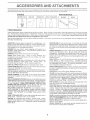
These accessories and attactanents were avai_aMe thro sgh most Sears retail outlets and senrice centers when the tractor was purchased
Most Sears stores cars order these terns for you when you provide the modeJ numl er of your tract(y.
SPARK PLUG
GAS CAN
ENGINE OiL
FUEL STABiLiZER
BLADES
BELTS
Sears offers a wide variety of att_ chments that fit your tractor_ Many of these are %ted below with brief explanations of how they (;an help
you This _istwas current at the tree of publication; however, t may change in future years - r'nore attachreents may be added changes
may be made }n these attachments er some may _o beget be ave }abie or fit your _odeL Contact your nearest Sears store for the
accessories and attachments
that are available for year tractor.
Most of these attachments
attaching and detaching.
do not reqaire additional h tches or conversion
AERATOR promotes deep root growth for a healthy lawn. 'Ta_
pored 2.54rich stee_ spikes mounted on 10 inch diameter discs
punctare hobs in soii at cone inter,vals to _et moisture soak in
Stee_ weight tray for increased penetration
BAGGER lets you collect
grass clippings and bares for a
healthier, nearer looking lawn. 'Two Permaeex containers hotd
30_ga_lon plastic bag&
BUMPER protects front end of tractor from damage
DARTS make hauiing easy
Vade!i _ of szes availabie, pk_s
accessories such as side panei kits, too_ caddy, cad cover,
pratective mat and doly
CORING AERATOR takes small plugs out of soil to allow mo}s
ture and nutrients to reach grass _oots. 36inch swath. 24
hardened steel coring tips 150 _b.capac ty weight tray
EASY O_L DRAIN VALVE makes o;_changes easier_ faster.
FRONT NOSE ROLLER canters ir front of mower deck to reduce
chances of scalping '_on uneven terrain
GANG H_TCN iets you taw 2 or 3 pui. behind attachments at once
such as sweepers dethatchers, aerators (not for use w}th tel}era,
caps or other heavy attachments)
GAUGE WHEELS on both sides of the mower deck _educe
chances d '°sca_ping" on uneven terrain For mower decks not so
CLOSE_OUT
and are designed for easy
SNOW BLADE forsnow removat say 14qnch high 424nch wide
Made ciears 38qnch path when angled _eftor dght Raises, b,aers
with side bver Adiustab!e skds rep_aceaMe, reversiMe scraper
bar (Use with tire chains and wheel we ghts andor rear drawbar
SNOWTRROWER has 40._rich swath Drum_type auger h_ndles
powdery and weVheavy snow
Mounts easily wit'_ simple pn
arrangement. Discharge chute adjusts from tractor seat. 6qnch
diameter spout discharges snow !0 to 50 feet. Lft contro_bd at
tractor seat (Use with chains and whe®_ weghts anWor rear
SPRAYERS use 12-volt DC e_eetdc motor that connects to the
tractor battery sr other 12ovott source
nciudes booms for
SPREADER/SEEDERS
make seed ng fert Izing and weed ki_l._
ng easy. Broadcast spreaders a_e abe useful _or granular d@
_:els and sand.
SWEEPERS _et you collect grass clippings and teaves.
T_LLER has 5 hp engine and 36- nch swath to prepare seed beds,
cultivate and compost garden residue. Titler has its own builtoin
loosens aoi! and flips thatch and
drawbar and go!
Optiona_ accessories
conved unit for
dethatching_ aerating, hilling ,without tools,
T_RE CHAINS are heavy duty; closely spaced extraqarge cross
_inks give smooth ride, outstanding traction.
PLATE K_T, once insta_ed, lets you
visibility, Hinged metal doors with catch Keeps operator warm
and d_, Remove vinyl eden and windshields for use as sun
protector n summer
Opt_ona! accessories
I_cl_de,
tinteW
tempered solid salety glass windshield with hand operated wiper
12_volt amber caution Hght for mounting on cab top.
VAC$ for powedui coi/ection of heavy grass clippings and ieaves,
Opt_oaa! wand attachment to pick up debris in hard to-reach
p_aces, VAC/CHIPPER includes a chipper shredder
WEIGHT BRACKET tot drawbar for snow removal applications
Uses (1) 55/b, weight,
MULCH RAK_DETHATCHER
MULCH|NG
kits (those iha_ do are indicated}
manual
RAMP TOPS AND FEET let you bad and unload tractor from a
pickup truck. Use with 2 x 8 or 2 x 10 _umber
ROLLER for smeother _awn sudace. 364nch wide, 18.cinch
diameter water4ight drum holds up to 390 tbs_ of weight Rounded
edges prevent harm to tad. Adjustable scraper autoraaticat_y
cleans dram
WHEEL WEIGHTS for rear wheels provide needed traction for
snow removal or dozing heavy mateda}s.
OF
Parts
Bag contents
shown
fuji size
(2) Sheet
Metal
Screws
1/2
ii
Ji
I
I/
Wheel
(1) 2o3/8_'Diameter Washer
(I) Locknut
3/8o.24
Boot
Owner's ManuaI
(I) Hex Bolt 1/2-13 x !
Pads bag contests
(1) Shoulder Bolt 5/16d8
not shown
full size
Steerir_g Wheet
_,..........................................................
/ Whee
x...............................................
/ /r_Ser_
(1) Lock Washer
i/2
(1) Washer
17/32 x I.-3/16 x 12 Gauge
(2) Keys
(2) He× Boits 1/4-20 × 3/4
(2) Hex Nuts !/4-20
(2} Washers
9/32 x 5/8 x 16 Ga,
(2) L ockWashers
1/4
15 Slope Sheet
6
Battery Caps
and Instructions
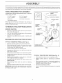
Your new tractor has been assembled at the factory with exception of those parts bft unassembled for shipping purposes.
To ensure safe and proper operation of your tractor, all parts and hardware you assemble must be tightened securely_ Use
the correct tools as necessapj to insure proper tightness
TOOLS
REQUIRED
FOR ASSEMBLY
A socket wrench set wiii make assembly easier. Standard
wrench sizes are listed
(!) 9/16" wrench
(1) 1/2" wrench
(2) W16" wrench
(1) 3/4" wrench
Utility knife
Tire pressure gauge
When nght and/eft hand is mentioned in ths manual, it
means when you are in the operat ng position (seated
behind the steering whee0,
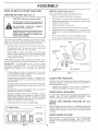
TO REMOVE TRACTOR
UNPACK
STEERtNG
WHEEL
ADAPTER
FROM CARTON
STEERING
BOOT
CARTON
TABS
Remove aH accessible bose pa_s and parts cartons
from carton (See page 6}.
STEERING
CuL from top to bottom along ires on all four corners
of caPon, and lay paneis fiat
o
SHAFT
Check for any additiona_ loose parts or cartons and
remove,
BEFORE ROLLING TRACTOR OFF SKiD
A_ACH
STEERING
WHEEL
(See Fig, 1)
o
Slide the steering bushing over the steering shaft.
o
Raise steering shaft forward untif screw holes in dash
Iine up with steering bushing
Instal two (2} sheet
meta! screws and tighten securely,
o
Position steedng boot over steering shaft.
o
Place tabs of steering boot over tab slots in dash and
push down to secure
Slide steering wheel adapter onto upper steering shaft,
Position front wheets of the tractor so they a re pointing
TO ROLL TRACTOR
,
Position steering wheel: so cross bars are horizontal
(left to right) and slide onto adapter.
Assemble
,
large fiat washer and 3/8_24 Iocknut and
Snap steering wheel
wheel,
o
Raise attachment lift lever to ts highest position
o
Release parking brake by depressing
_'
Place freewheel control in freewheeling position to
disengage transmission (See "TO TRANSPORT" in
Operation section of this manual}_
Ro_ttractor backwards off skid.
insert into center of steering
o Remove protective plastic from tractor hood and gr/I
IMPORTANT;CHECK FOR AND REMOVE ANY STAPLES
iN SKID THAT MAY PUNCTURETIRES WHERE TRACTOR
IS TO ROLL OFF SKID,
o
,
7
OFF SKID (See Fig, 8)
clutch/brake
Remove banding holding discharge guard up against
tractor,
HOW TO SET UP YOUR TRACTOR
PREPARE
BAKERY
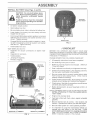
INSTALL
SEAT (See Fi9, 3)
Adjust seat before tightening adjustment boit.
(See Fig, 2)
Remove cardboard packing on seat pan
Place seat on seat pan and assemble shoutder bolt.
CAUTION: Wear eye and face shiol&
Assemble adiustment bot bck washer and fiat washer
loosely Do not tighten
Tighten shoulder bolt securely.
Do not smoko_ Fumes from cha_ged
bakery acid are exp[osive_
Lower seat into operating position and sit on seat.
Slide seat until a comfo _abte position is reached which
allows you to press clutch/brake pedal atl the way
down.
Read the instructions
included with the
battery vent caps, Always wear gloves,
clothing and goggles to protect your
hands, skin and Byes,
Get off seat without movng its ad}usted post on.
o
Raise seat and tighten adjustment bo_t securely.
Your tractor has a battery charging system which is suffio
cient for normal use However periodic charging of the
batter;/with an automotive charger wilt extend ts life
,
See instructions paek÷d with vent caps in pa_s bag.
o
Fill battery with ac{& Fill each cell until it reaches the
bottom of the vent wells. DB not ovedilt.
SEAT
SEAT PAN
SHOULDER
BOLT
correct level is reached_
Whiie battery is standing (after adding acid) and later, whiIe
batteG_ s being charged, continue wth assembiy of tractor
IMPORTANT:
TO MAXIMIZE THE LIFE: OF YOUR
BATTERY T/S NECESSARY THAT THE BATTERY BE
CHARGED BEFORE USE FAILURE TO CHARGE
BATTERY CAN RESULT IN A SHORTENED BATTERY
LiFE
o
Charge batteD, at a rate of 6 amperes for 1 hour Use
a 12 vBtt battery charger Observe a_l safety precau.
tions required for battery charg ng
o
Cheek the acid evet after the battery is charged If the
acid has faIIen below the corroct eveL add distif ed or
iron frBe water.
o
FLAT WASHER
FiG, 3
CHECK TIRE PRESSURE
_he tires on your tractor were overinflated at the fact:ocJ for
shipping purposes. Correct tire pressure is impodant for
best cutting performance.
Install the vent caps to cover the vent wels_ Wash the
top of tise battery with water to romove any acid, then
wpe dry_
Reduce tirB pressuro to PSi shown in "PRODUCT
SPECIFICATIONS" ORpage 3 of this manual.
Check batteq¢ case for teakage to make sure that no
damage has occurred in handling.
-
Dispose of excess battery acid
NeutraIize
LOCK WASHER
ADJUSTMENT
BOLT
CHECK
acid for
DECK
LEVELNESS
For best cutting results, mower housing should be propedy
leveled. See "TO LEVEL MOWER HOUSING" in the
Service and Adjustments section of this manual
paddle whi_e addng baking: soda unti! the addition of
more soda causes no more foaming.
CHECK
Follow instructions on how to insta![ batte_7
FOR
PROPER
POSITION
OF ALL
See the figures that are shown for replacing motion and
mower btade drive botts in the Service and Adjustments
section of this manual. Verify that the belts are routed
CUT AWAY VIEW
CHECK
SYSTEM
After you learn how to operate your tractor, check to see
that the brake is properly adiusted. See "TO ADJUST
BRAKE*' in the Service and Adiustments section of this
manuaI.
BATTERY
CELL ACiD
LEVEL
FiG. 2
BRAKE
8
INSTALL
BATTERY
(See Figs,4 and 5)
CAUTtON: Do not shoA batte_'y termi_
nats_ Before instsIHn 9 baAery_ remove
meta_ bracetets_ wristwatch
bands_
BATTERY
DOOR
Positive terminat must be connected
first to prevent sparking from accideno
tat 9_oundtng,
Lift seat to raised position,
o
Open battery box dDor.
o
Be sure battery drain tube is attached to battehf box
o
Lower batten/ into battery box wth battery term hats
toward front of tractor.
,
First connect RED battery cable to positive (+) terminal
with hex bo}t, flat washer, lock washer and hex nut as
shown, T ghten securely°
o
Connect BLACK grounding cab e to negatwe (_) termio
VENTS CAPS
FtG, 5
nai wth remaining hex [_olt, flat washer, bck washer
and hex nut. Tighten securely
,
Close batteP/box
dOBr.
Open battery box door for:
o
hspection foi secure connectons
o
(to tighten hard
BEFORE YOU OPERATE: Ak_ LT'qJOY YOUR NEW
TRACTOR, WE W/St: _'TO ASSURE THAT YOU RECEIVE
%H\EBES T P_R
NCE AND SA TISF74CTION FROM
7HtS QUAUT Y PRODUCX
Test ng battery.
,Jumping (if required)
Periodic charging,
PLEASE REVfEW THE FOLLOWING CHECKLIST:
BATTERY
BOX DOOR
NEGATIVE
(BLACK)
CABLE
LOCK
WASHER
Ali assembly instruc'Iions have been completed
/
No remaining tDBSBparts in cartDn
v"
Battery is properly prepared and charged.
1 hour at 6 amps)_
v"
Seat is adjusted comfortably
v"
All tires are properly infiated_ (For shipping purposes_
the tires were overinflated at the factory)
/
Be sure mower deck is properly Ieve/ed side.4o_sidd
frontqo._rear for best cutting resu}ts_ (Tires must be
property inflated for bveiing).
/
Check mower and drive belts, Be sure they are routed
prBpedy around pulleys and inside all be_t keepers.
/
Check wiring See that aI! connections are stll secure
and wires are properly clamped,
/
Before driving tractor, be sure freewheel control is in
HE×
BOLT
and tightened securely.
/
Engine oH is at proper level,
/
Fuel tank is filled with fresh, ciean, regular unleaded
_/
Become famiiiar with ail contn_ls _ their location and
function, Operate them before you sta_ the engine.
¢
Be sure brake system is in safe operating condition,
,/
It is imporlant to purge the transmission before you
operate your new tractor for the first time. Follow
NEGATIVE (-) TERMINAL
FIG, 4
(Minimum
WHILE LEARNffqG HOW 70 USE YOUR 'TRACTOR, PAY
EXTRA A TT_NTION TO "THE FOLLOWtNG JMPOR
TANT ITEMS.:
FLAT
POSTmVE (÷) TERMSNAL
/
9
S_ON" inOperation section of this manual),
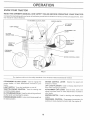
KNOW YOUR TRACTOR
READ THIS OWNER'S
_IANUAL
AND SAFETY
RULES
BEFORE
OPERATING
YOUR TRACTOR
Compare the illustrations with you r tractor to familiarize yourself with the eLations of various controls and ad ustrRents. Save
this manual for future reference
ATTACHMENT
CLUTCH LEVER
IGNiTiON
SWITCH
UGHT SWITCH
CLUTCH!
BRAKEPEDAL
THROTTLE/
CHOKE
CONTROL
FREEWHEEL
CONTROL
PARKING
LEVER
DRAKE
MOT}ON CONTROL
LEVER
F_G. 6
Our tractors conform to the safety standards of the Amer can National Standards hstitute,
A_ACHMENT
CLUTCH LEVER; Used to engage the
mower btades, or other attachments mounted to your
tractor.
MOTION CONTROL LEVER:
Selects the speed and
direction of tractor.
U_ LEVER PLUNGER: Used to re,ease attachment Iift
LIGHT SWITCH: Turns the headlights on and offi
THRO_L_CHOKB
CONTROL:
Used for starting and
controlling engine speed,
CLUTCHTBRAKE PEDAL: Used fordec/utchingand brako,
ing the tractor and sta_ing the eng Re,
PARKING BRAKE LEVER: Locks clutch/brake pedal rite
the brake position°
lever when changing its position,
A_ACH_gENT
LIFT LEVER: Used to raise, lower, and
adiust the mower deck or other attachments mounted to
IGNITION SWITCH:
Used for stading and stopping the
FREEWHEEL CONTROL; Disengages transmssion for
pushing or slowly towing the tractor with the engine oil
10
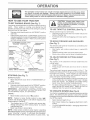
HOW TO USE YOUR TRACTOR
TO SET PARKING
BRAKE
(See Fig, 7)
Your tractor is equipped with an operate r presence sensing
switch
When engine is running, any attempt by the
ope_tDr to leave the seat without first setting the parking
brake wili shut off the engine
Depress clutch/brake pedal into full 'BRAKE '_positior_
and hold.
Place parking brake lever in 'ENGAGED _position and
release p_essure from ciutchibrake pedal Pedal should
remain in"BRAKE '_pos tion Make sure park ng biake
wil! hold vehicle secure.
TO USE THRO_LE
CONTROL
(See Fig° 7)
Always operate engine at fut! throttle,
Operating engine at _ess than fun thmttb reduces the
batleq_, charging rate_
Fu!! thmttte offers the best bagging and mower pedor_
mance
TO MOVE FORWARD
AND BACKWARD
(See Fig, 7)
The direction and speed of movement is contrelted by the
motion cDntrDI !ever.
Stad tractor wth motion control lever n neutral (N)
_GNtT{ON
,
MOT}ON
CONTROL
LEVER
Release pa_king brake and c!utch/brake pedal.
S_owiy move motion co_trO lever to desired post on.
TO ADJUST
MOWER
CU_[NG
HEIGHT
(See Figo7}
The pestion of the attachmer_t iift /ew_r determi_es the
cutting heght
,
Grasp Ift lever
,
Press plunger with thumb and move ever to des red
CLUTCH/DRAKE
PEDAL"DmVE*'POSmON
PABKfNG DRAKE
'DISENGAGED'
POS_T_ON
FIG, 7
STOPPING
(See Fig, 7)
MOWER BLADES °
Move attachment dutch iever to "DISENGAGED"
sitios.
GROUND DRIVE
po.*
Depress clutch/brake pedal into fuII "BRAKE*' pDsitiOn.
,
Move motion control lever to neutral (N) position.
_IPaPORTANT; THE MOTION CONTROL LEVER DOES
NOT RETURN TO NEUTRAL (N) POSITION WHEN THE
CLUtCH/BRAKE PEDAL 1S DEPRESSED
ENGINE Move throttle control to sbw (_)
position.
NOTE:
Failure to move throttle contrel to sbw (_}
position and allowing engine to idle before stopping may
cause engine to "backfire*'.
o
The cutting height range is approx mately t -1/2 to 4. The
heights are measured from the ground to the blade tip wit/_
the engine nDt runn[ng_ These heights are approximate
and may vary depending upon soil conditions, height of
grass and types of grass being mowed.
° The average _awnshould be cut tD approximately 21/2
inches during the cool season and to over 3 inches
durng hot months. For healthier and better IDDk_ng
lawns, mow often and after moderate growth_
°
For best cutting pedDrmance, grass over 6 inches in
height should be mowed twicD. Make the first cut
relatively high; the second to desired heighL
TO OPERATE
MOWER
(See Fig, 8)
Your tractDr is equipped witi_ an operator presence sensing
switch. Any attempt by the operator to leave the seat with
the engine running and the attachment clutch engaged wl/
shut off the engine.
,
Select desired height of cut
,
Stad mower blades by engaging a_tachment clutch
control.
Turn ign tion key to 'OFF" position and remove key
Always remove key when leaving tractor to prevent
°
unauthorized use.
,
Never use choke to stop engine,
NOTE: Under ce_ain conditions when tractor is standing
idle with the engine running, hot engine exhaust gases may
cause "browning' of grass, To eliminate this possibility,
always stop engine when stopping tractor on grass areas. 11
TO STOP MOWER BLADES odisengage attachment
dutch control.
CAUTION:
Do not operate the mower
without e_ther the entire grass catcher,
on mowers so equipped, or the discharge guard tn place,
"ENGAGED"
POSITION
ATTACHMENT
LEVER
HiGH POntoON
LOW
POS_T_ON
F_G, 9
BEFORE STARTING
THE ENGINE
CHECK ENGINE O}L LEVEL (See Fig, 14 & 15)
o
o
FIG 8
TO OPERATE
The eng nen your"tractor has been sh pped, from the'
factoryl aiready fIed wth sum_'_er wei{ii:_t ol.
Check engine el wth tractor on tevel ground
o
Unthread and remove oi fill cap/dipstick; wipe oil off.
Reinsert the dipstick into the tJbe and rest el fii/cap on
the tube. Do not Ihread the cap onto the tube. Rernove
and read oii ieveL ff necessary, add oi unti FULL'*
mark on dipstick is reached. Do not oved l/.
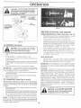
o
For coid weaiher operation you should change oi for
easier sta£ing (See OIL. VISCOSITY CHART' in the
Customer Respons b I ties secl or_ of ths manuat}
To change engine el, see the Cus omer Responsib i
tes section in ths man al
ON HILLS
o
Choose the slowest speed before stading up or down
hills.
o
Avod stepping or changing speed on Mils
If slowing is necessary, move th_oltte con' rol tever to
slower position.
ADD GASOUNE
o
FI fu_}I tank
Use fresh, clean re _xb:_.l
uneaded
gasefine (Use of leaded gasoline wlI ncrease cal_bon
and bad oxide deposits and reduce rave ire}.
_MPORSANT: WHEN OPERATING IN TEM_:_ERATURES
BELOW 32"F(@CX USE P:_ESH CLEAN WINTER GRADE
GASOL NE TO HELP NSURE GOOD COL[:} WEATHER
START NG
'_
If stoppin 9 is absok.ltely necessary push clutch/brake
pedal quickly to brake position and engage parking
brake
o Move motion control ever Io neutra_ (N) position_
iMPORTANT:
THE MOTION CONTROL LEVER DOES
NOT RETURN TO N UTRAL (N) POSITION WHEN THE
CLUTCH/BRAKE PEDAL _S DEPRESSED.
o
o
,
WARN_NG; Experence indcates that a_coho blended
fueB (caNed gasoho or using ethanol or methanol) can
attract moisture whch leads to separat}on and format on of
acids during storage. Acidc gas can damage the fuel
system of an engine whie in storage. To avoid engine
prob/ems, the fuel system shouId be emptied before storage of 30 days or Ionger_ Drain the gas tank, sta_l the
engine and Iet t run untit the fuel fees and carburetor are
em_y
Use fresh fuel next season. See Storage _nstruc
tions for addtonal information.
Never use engne or
carburetor cleaner products n the rue tank or permanent
damage may occur.
To testa d movement, slowly r*e_easeparking brake and
c_utch/brake pedal.
Sfow/y move motion controi lever to slowest setting.
Make all turns siowly.
TO TRANSPORT
(See Figs. 6 and 9)
When pushing or towing your tractor be sure to disengage
transmission by placing freewheel control in freewheeling
position Free wheel control is located at the rear drawbar
d tractor
,
Raise attachment
meat lift contret.
lift to highest position with attacho_
Donor push or taw tractor at more than twe (2) MPH.
To reengage transmission reverse above procedure.
NOTE: Te protect hood from damage when transporling
your tractor on a truck or a t railer, be sure hood is closed and
secured to tractor. Use an appropriate means of tying hood
to tractor (rope, cord, etc).
12
OPE
TO START
ENGIINE (See Fig_ 7)
When sta_ing engine for' the frst time or f engine has rur'l
out of fue!, it wiff take extra cranking tree to move fuet fcom
the tank to the engine,
o
-
Depress dutch/brake pedaI and set parking brake,
Place motion control lever in neutra_ (N) pos tion.
o
Move attachment clutch to "DISENGAGED" posit on.
Move throttle control lever to choke (i's!) position for
cold engine start. For warm engine star1, move thrott e
centre! to fast (@) posit;on.
InseR key into ignition arid turn key c!ockwiseto"START"
o
o
o
traCtOr moves appmxmately
five (5) feet return the
moton control _ever to the neutraI (N) position, Repeat
ths procedure with the rnotion contre_ iever three (3)
tmes.
Your tractor is now purged and now ready for normai
MOWING
seconds per minute, ff engine does not sta_ after
several attempts_ move throttle contro_ to fast (@)
position, wait a few minutes and try again
When engine starts, slowly move throttle control ever
to desired running speed,
Aiow engine to warm up for a few minutes before
engaging drive or attachments
PURGE TRANSMISS_ON
To ensure preper operation and pedormance, t is recom_,,
mended that the transmiss on be p Jrged before operating
tractor for the first trne. Ths precedure wtl remove any
trapped a{r nside the transmission which may have devel_
oped during shipping of you_ t_sctor,
IMPORTANT: SHOULD YOUR TRANSMISSION REQUIRE
REMOVAL FOR SERVICE OR REPLACEMENT,
T
SHOULD BE PURGED AFTER REINSTALLATION
BEFORE OPERATING THE TRACTOR_
Place tractor safely on level sudace with engne off and
parking brake seL
TiPS
o
Tre chains cannot be used when the mower housing
is attached to tractor.
o
Mower should be properly leveled for best mowing
performance See TO LEVEL MOWER HOUSING"i
the Ser_..,iceand Adjustments section of this manuai
The ieft hand side of mower shou}d be used for trim
o
NOTE: if at a hfgh altitude (above 3000 feet) or in cetd
temperatures (below 32{F), the carburetor fuel mxture
may need to be adjusted for best engine pedormance, See
"TO ADJUST CARBURETOR" in the Service and Adjust
merits section of ths manua_
o
Sitting inthetraclor seat, start engine, Aftertheengine
is running, move throttle contro_ to half (1/2) speed,
With motion contrei lever in neutral (N) position, s!owly
disengage clutch/brake pedaI,
Slowly move motion cont_)l _ever fo_dard after the
°
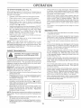
Drive so t_at c/ppings are discharged onto the area
that has been cut Have the cut area to the dght of the
machine This w_i result in a more even distribution of
clippings and more uniform cutting
o
When mow _g fa,rge areas, stail by turning to the right
so that clippii'_gs' witi discharge away friJm shrubs
fences, driveways, ete,_ After one or two rounds, mow
in the opposite d rection making teft hand turns until
finished (See Fif_. i0 )
o
is extremely tail, it should be mowed twice to
load and possible fire hazard from dried cIippings. Make first cut relatively high; the second to the
desired heig!' t.
o
Do not mow grass when it is wet, Wet grass will plug
mower and leave undesirable clumps, Allow grass to
dry before mowing.
•
Always operate engine at full throttle when mewing to
assure better mowing performance and proper dis
charge of material, Regulate greund speed by select
ing a _ow enough gear to give the mower cutting
pedormanee as well as the quality of cut desired.
When operating attachments, select a ground speed
that wil! suit the terrain and give best performance of
the attachment being used
o
Sitting in the tractor seat, stalt engine. After the engine
disengage clutch/brake pedal
Move motion control lever to fut! forward position and
hold for five (5) seconds, Move lever to full reverse
position and hold for five (5) seconds, Repeat this
procedure three (3) times.
l
NOTE: During this procedure there wil! be no movement of
drive wheels. The air is being removed from hydraulic drive
Move motion control Ieverto neutral (N) position. Shut
off engine and set parking brake
F_G. 10
of manual).
13
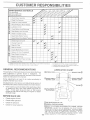
GENERAL
RECOMMENDATIONS
LUBRICAT_ON
CHART
The warranty on this tractor does not cover items that have
been subjected to operator abuse or neg[igence
]o
receive flf[I vat_e from the warranty_ operater must maintain
tractor as instructed in this manual
Some adiustments wiil need to be made periodicaly
properly ma r_tain your tractor
to
All aqustrnents in the Service and Adjustments section of
this mant_a_should be checked at least once each season.
Once a year you shoud replace the spark pk_g ciean
or replace air filter, and check btades and beets _or
wear A new spark plu9 and c_ean air fi_ter assure
proper airquel mixture and help your engine run bette_
BEFORE
EACH
CLUTCH PIVOT
USE
,,
Check engine oil levet,
o
Check b_ake operation
o
,,
Check tire pressure.
Check for loose fasteners.
(_SAE
3(} MOTOR OIL APi., 5G
_GENERAL
@REFER
PURPOSE
GREASE
TO CUSTOMER
R_SPONSIBIL[TtES
"ENGINE"
SECTION
tMPORTANT:
DO NO'}" O{L OR GREASE THE PSVOT PO}NTS
WHICH HAVE SPECALNYLON
BEARINGS
VISCOUS LUBRb
CANTS WiLL ATTRACT
DLJ_STAND DIRT 'THAT WILL SHORTEN
THE IFE
OF THE SELF LUBRICATING
BEARINGS
IF YOU
FEEL THEY MUST' BE LUBRICATED,
USE ONLYADRY
POW14
DERED
GRAPHITE
TYPF
L JBRICANT
SPARING.Y,
o
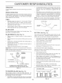
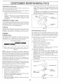
To check blade balance, you will need a 5/8" diameter
AIways observe safety rules when pedormieg any mainteo
nance
BRAKE
S_ide blade on to an unthreaded po_ion of the steeI bet
or pin and hold the bolt or pin paral/et with the ground
If blade is balanced, it shoWd remain in a horizontal
position, If either end of the blade moves downward
sharpen the heavy end until the blade is balanced
OPERATION
if tractor requires more than six (6) feet stopping distance
at high speed in highest gear, then brake must be adiusted
(See "TO ADJUST BRAKE" in the Sewice and Adiusb
meets section of this manual)
NOTE: Do not use anai! for balancing blade. The lobes of
the center hole may appear to be centered, but are not,
Maintain proper' ar pressure in all tires (See 'PROD°
UCT SPECIFICATIONS '_or page 3 of this manuai)
Keep tires free of gaso/ine_ oil or insect control chemi_
ca/s which can harm rubber
o
5/8" BOLT
OR PIN
Avoid stumps, stones, deep ruts, sharp objects and
other hazards that may cause tire damage.
BLADE
CARE
For best results mowe blades must be kept sharp,
p_ace bent or damaged blades_
BLADE
REMOVAL
F_G. !2
Re
BATTERY
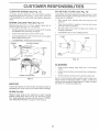
Remove hex bolt, lock washer and flat washer secudng
blade.
Install new or resharpened blade with traiiing edge up
towards deck as shown
o
(See Fig. 13)
Your tractor has a battery charging system which is suffi.cient for _orma} use. However periodic chac:_ing of the
batten! with an ¢_utomotw; charger will e×tend ts fife
(See Fig, 11)
Rase mower to highest position to atiow access to
blades
.
BLADE
Reassemble hex bolt, fock washer and flat washer n
exact order as shown
o
Acid soiut on ievel in each battery cell shoud be ew:_n
wilh bottoms of vent weIIs_ Add only distilled or i_onfree
water if necessarj. Do not ovediit
o
Keep batte_ and terminals clean.
o
Keep battery bolts tight
o
Keep vent caps tght and small vent holes in caps open.
o Tighten bo_t securely (30G5 Ft Lbs torque)_
IMPORTANT: BLADE BOLT IS GRADE 8 HEATTREATED,
Recharge at 6 amperes for 1 hour°
TO CLEAN BATTERY AND TERMINALS
NOTE: We do not recommend sharpening Made-. but if you
do, be sure the btade is ba arced,
Corrosion and d_l on the batte_'7 and termina s can cause
the battery to 'teak!' power.
Open battery' box doer.
MANDREL
ASSEMBLY
BLADE
o
Disconnect BLACK batter! came first then RED bat-.
teq/cable and remove battery from tractor
o
Wash battery with solution of four tablespoons d
baking soda to one gallon of water. Be careful not to get
the soda solution into the ceils.
o
Rinse the batten/with
plain water and dry,
Clean terminals and battery cable ends with wire brush
until bright.
_
REX BOLT (GRADE 8) _
_A GRADE 8 HEAT TREATED BOLT CAN BE
iDENTIFIED BY SiX LINES ON THE BOLT HEAD,
FIG, 11
TO SHARPEN
BLADE
o
Coat terminais with grease or petroleum ieHy.
•
Reinstall batter,/ (See "INSTALL
Assembly secti6n of this manual),
CUT AWAY VIEW
in the
VENT CAP
VENT
WELL
(See Fig, 12)
Care should be taken to keep the blade bafance&
An
unbalanced blade wili cause excessive vibration and even°
tual damage to mower and engine,
o
BATTERY"
BATTERY
CELL ACID
LEVEL
The blade can be sharpened with a file or on a grinding
wheel, Do not attempt to sharpen while on the moweh
15
FiG. 13
TRANSAXLE
COOLING
The fan and cooiing fins of transmission sho._ld be kept
ctean to assure proper cooling
Do not attempt to clean fan or transmiss on white engine is
runn ng or while the transmission is hot.
o
Inspect cooling fan to be sure fan blades are intact and
clean.
-
manual.
inspect cooting fins for di_t grass clippings and other
materials
To prevent damage to seals, do not use
compressed air or high pressure sprayer to clean
TRANSAXLE
PUMP
O_L F_LL
CA[_IPSTlCK
FLUID
The transaxie was sealed at the factory and fiuid ma nteo
nance is not required for the/fe of the transaxle Shoutd the
transax/e ever _eakor require servicing, contact your near
est authorized service centeffdepadment.
OiL DRAIN
PLUG
F_G. 15
Cheek V.-beits for deterioration and wear after 'i00 hours of
operation and replace if necessary The belts are not
adjustable_ Replace beits if they begin to slip from wear.
AR
HLTER
(See Fig, 16)
Your engine wil not tun propedy using a d_y air fi!te_
Clean the foam pro-cleaner after every 25 hours of opera.ties or every season. Sewice paper ca_ridge ever}, 100
hours of operation or every season, wh chever occurs first.
Only use high qual ty deterge_ t oi rated with API sewice
ciassification SG
SeIect the ols SAE viscosity grade
accord ng to your expected operating temperature
Service air c!eaner more often under dusty conditions
Remove knob and cever_
Remove wing nut and air cIeaner from base.
TO SERVICE PRE._CLEANER
o Slide foam preo.cleaner off ca_ridge.
SAE VISCOSiS Y GRADES
Wash it n liquid detergent and water_
Squeeze t dry in a clean cloth.
_'_
'C
28
59*
0"
-2g"
3:}
82
4;}'
,i0"
B0
_3
i0
10 '[_'
20
] EMPERA_T JRB RANGI:[ AN]° C PA' _;;} BE _'©RE t,,iEX'[ el,
30
o
Saturate it in engine oit. Wrap t in clean, absorbent
cloth and squeeze to remove excess oil
TO SERVICE CARTRIDGE
40
C ¢#NG_I
FIG, 14
o
NOTE; Aithough mu/tioviscosity oits (5W30_ 10W30 etc)
mprove starling in cad weather, these multioViSCOsityois
wilt result in increased oil consumptior_ when used above
32_'F. Check your engine oil level more frequently to avo d
possible engine damage frorn running _ow on oii.
o
Change the oil after the first two hours of operat on and
every 50 hours thereafter or at least once a year if the tractor
is not used for 50 hours in one year.
Gently tap the flat side of the paper cartridge to dis °
todge dirt. Do not wash the paper cadddge or use
pressurized air, as this wiii damage the ca_ddge.
Replace a dffly, bent or damaged cartridge.
Reinstall the pro cleaner (cleaned and o/ed) over the
paper ea£_idge.
Reassembie air ctesner wing nut cover and tighten
knob securely.
Check the crankcase oil ievel before sta rting the engine and
after each eight (8) hours of operation. Tighten oii filf cap/
dipstick securely each time you check the oil ievel.
TO CHANGE ENGINE OIL (See Fig. 14 and !5)
CARTR_DGENUT
COVEI
Determine temperature range expected before oil change.
All oi! must meet APi sewice classification SG.
Be sure tractor s on levei sudace
o
o
Oil wi_/drain more freely when warm.
Catch oii in a suitable container.
,
Remove oil fii/cap/dipstick. Be careful not to allow dirl
to enter the engine when changing oil
Remove drain pk_g.
,
After ot has drained completely,
and tighten securely.
PAPER
CARTRIDGE
BASE
replace oil drain plug
FIG, 16
16
CLEAN
A_R SCREEN
(See Fig, 15)
}N-LINE
COOLING
,
FINS (See Fig, 17)
Remove screws from blower housing and iifl housing
and dipstick tube assembly off engine
o
Cover oi{ fill opening to prevent entry d did
o
Use compressed air or stiff br stle brush to tt_o_eugMy
clean engine cooiing fins_
To reassembie,
SCREWS
With engine coo_, remove fiiter and plug fuel Iine
sections.
Ptace new fuei fiiter in position in fuel Ine with arrew
pc nting towards carburetor
Remove any dust, di_ or oil frem engine cooling fns to
prevent engine damage from overheating°
o
(See Fig, 18)
The fueI %er shoud be replaced once each season. _ffuet
filter becomes clogged, obstructing fuel flow to carburetor,
replacement is required
Ar screen must be kept free of dirt and chaff to prevent
engine damage from overheatin G C_ean with a wire brush
or compressed air to remove did and stubborn dded gum
fibers.
ENGINE
FUEL F}LTER
Be sure there are no rue! iine _eaks and c_amps are
properly positioned.
o
Immediately wipe up any spilled gasoline
CLAMP
reverse above pracedure
BLOWER
ROUSING
NG, 18
SPARK
PLUG
ENGINE
COOUNG
F_NS
Ciean engine, battery, seal finish, etc. of all foreign
matter_
o
Keep finished sudaces and wheels free of all gasoline,
oil, elc_
o
Protect painted sudaces with automotive type wax.
We do not recornmend using a garden hose to e_ean your
tractor unless the eiectricaJ system, muffler, air filter and
carburetor are covered to keep wa£er ouL Water in engine
can result in a shodened engine ire.
F_G. 17
Inspect and replace co_roded muffter and spark arrester (f
equipped) as it could create a fire hazard and/or damage.
SPARK
•
PLUGS
first. Spark p_ug type and gap setting is shown in "PROD°
UCT SPECIFICATIONS" on page 3 of this manual
17
E
CAUTION:
BEFORE PERFORMING
clutchtbrake
ANY SERV|CE OR ADJUSTMENTS:
-
Depress
o
,
,
P_ace motion contro_ _ever tn neutral (N) position,
Place attachment clutch in "DtS,ENGAGED" position,
Turn ignition key "OFF" and remove key,
pedal fully and set parking
brake.
o
o
Make sure the b|ades and all moving parts have completely stopped,
Disconnect spark plug wire from spark ptug and place wire where it cannot come tn contact with
CLUTCH
TO REMOVE
MOWER
CLUTCH
(See Fig° I9)
Move attachment lift tever forward to lower mower to its
_,
Roll belt off engir_e putiey
o
D _ssonr_ectc_utch rod from clutch _ever by removiR_
retainer spring.
o
Disconnect anti._sway bar frem chassis bracket by
removing retafner spr}ng_
o
Disconnect suspension arms from rear deck brackets
by removing retainer spdngs.
o
Disconnect front links from deck by removing retainer
o
Raise lift _ever to raise suspens
out from under tractor,
on arms_ Side
ROD
SPR_NG
Mewer wilt be easier to remove from the rght sde of tractor.
o Place attachment clutch •_n ' DISENGAGE D" poe it on
•
SUSPENSION
ARMS
ENGINE
PULLEY
mower
ANTe-SWAY BAR
RETAINER
SPRINGS
(BOTH SfBES)
_MPORTANT:
IF AN ATTACHMENT
OTHER THAN THE
MOWER _S TO BE M©UNTED
1O _HE _RACTOR,
THE
R,H AND LH, SUSPENSION
ARMS MUST BE REMOVED
FROM TRACTOR,
F_G, 19
TO _NSTALL
MOWER
(See Fig, 19)
o
Rafse attachment lift lever to ts highest position.
o
S_kJemower under tractor with d scharge guard to right
side af tractor_
o
Lower lift lever to its lowest position.
o
Insta_i mower in reverse order of removal instruct ors
LEVER
t8
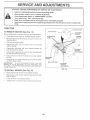
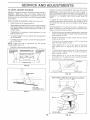
TO LEVEL
MOWER
HOUSING
FRONT TO-BACK
ADJUSTMENT
(See Fig& 22 and 23)
IMPORTANT:
DECK MUST BE LEVEL StDE_T'O_SiDE
iF
THE FOLLOWING
FRONT-TO.BACK
ADJUSTMENT
IS
NECESSARY
BE SURE TO ADJUST BOTH FRONTUNKS
EQUALLY
SO MOWER
W_LL STAY LEVEL SIDE-TOo
SIDE
Adiust the mower whle tractor is parked on fevet ground or
Make sure tires are propedy inflated (See
'PRODUCT SPECIFICATIONS" on page 3 of this manual).
If tires are over or undednfiated, you wil not proper_y adi Jst
your mower,
To obtain the best cutting results, the mower housing
should be ad}usted so that the front is approximately I/4," to
3/4' Iower than the rear when the mower is in its highest
SIDE,.TO_SIDE ADJUSTMENT (See Figs 20 and 21}
o Raise mower to its highest position.
At the midpoint of both sides of mower_ measure height
from bottom edge of mower to ground Distance'A'on
both sides of mower should be the same or within 1/4"
of each other,
•
Check adjustment on right side of tractor, Measu e dis.tance "D' directly n front and behind the mandrel at bottom
edge of mower housing as shown
If adjustment is necessary, make adiustrTent on one
side of mower oniy.
To raise one side of mower, tighten tiff rink adjustment
nut on that side.
o
NOTE: Three fut_ turns of adjustment
mower height about 1/8'
o
o
To lower one side d mower, loosen iift link adjustment
nut on that side.
Recheck measurements
if Inks are not equa_ n length, adiust one tink to same
_ength as other link
To tower fn:>nt of mower bosen nut 'E" on both front
/inks an equal number of tums_
nut wifl change
When distance 'D' s 1/4' to 3/4,'_lower at front than
rear tighten nuts "F' aga nst trunnion on both fi_ont
links.
after adjusting
o
"10raise front d mower, loosen nut"F' from trunn on on
both front links. T ghten nut 'E_ on both front links an
equal number of turns
o
When distance D" is 1/4' to 3/4 ' lower at front than
rear, tig _ten nut _F'_against trunnion or' both front links.
Recheck sideqo.,s de adjustment
FiG 20
FIG, 22
BOTH FRONT LINKS MUST BE EQUAL IN LENGTH
LIFT LINK
ADJUSTMENT
NUT
FIG, 21
NUT "E'
NUT "F"
FRONT LINKS
19
TRUNNION
FIG, 23
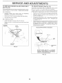
TO REPLACE
MOWER
BLADE
DRIVE
BELT
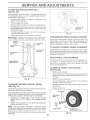
TO ADJUST
(See Fig. 24)
if tractor requffes mere than six (6) feet stopping distance
at high speed in highest gear, then brake must be adiusted
BELT REMOVAL
Remove mower from t@_ctor (See "TO REMOVE
MOWER" in this section of this manual
o
Work belt off both mandrel pulleys and id{er pulley.
,
Pull belt away from mower
BELT INSTALLATION
..
,
Instaii new belt in reverse order of removal
o
Make sure belt is in ali puItey grooves and inside a}l belt
MANDREL
(See Fig. 25)
Your tractor is equipped with an adjustable brake system
which is mounted on the fight side of the transaxte.
The mower Made drive belt rnay be replaced withoL_ttools_
Park the tractor on leve_ surface. Er_gage parking brake°
o
BRAKE
,
Depress ciutch/brake pedal and engage parking brake.
o
Measure distance between brake operating arm and
nut "A" on brake rod.
o
_fdistanceisotherthant_3/4"
!oosen jam nut andtum
nut "A" until distance becomes 1_3/4L Retighten iam
nut against nut 'W'.
still greater ttsan six (6) feet in highest gear further
maintenance is necessa_
Contact your r earest au _
thorized sewice center.
_DLER
PULLEY
W_TN PARKtNG BRAKE "ENGAGED"
FIG, 24
DO NOT" TOUCH THiS NU_
_F FURTHER
BRAKE
ADJUSTMENT
_S NECESSARY
CONTACT
YOUR NEAREST
AUTHORIZED
SERVICE CENTER!DEPARTMENT
F_G. 25
2O
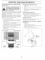
TO REPLACE MOTION DRIVE BELT
(See Fig. 26)
Park the tractor on Ievei su#ace. Engage park ng b_ake_
For assistance, there is a beit insta/ation guide decal on
bottom side of left footrest
,
,
Remove mower (See 'TO REMOVE MOWER" in tMs
section of this manual)
Remove upper belt keeper.
o
Remove beit from stationary idler and clutching idler.
Pull belt slack toward rear of tractor. Carefully remove
belt upwards from transmission input pulley and over
cooling fan blades.
o
Pull belt toward front of tractor and remove downward
from around engine pulley,
o
Install new belt by rever:s ng above procedure.
IMPORTANT;
MAKE SURE UPPER BELT KEEPER iS
POSiTiONED PROPERLY BETWEEN LOCATER TABS.
\
ADJLtS
_ MFN'f
,,OCKNU'_
F_G. 27
TRANSMISSION
REMOVAUREPLACEMENT
Should you_ transmission require
replacemenL t shoutd be purged
before operating the tractor. See
SION '_'in Operat on sect on of this
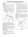
TO ADJUST
STEERING
removal for service or
after reinstal/atioe and
_PURGE TRANSM/S
manual
WHEEL
AUGNMENT
_[steering wheei crossbars are not horizontal (!eft to right)
when wheels are positioi'sed straight forward remove steer.
ing wheel ard reassemble per insb uctions in the Assembly
sect on of this manual.
FRONT WHEEL
TOE4N/CAMBER
The frort whee! toeqn and camber are not adjustable on
your tractor If damage has occ_._rredto affect the front
wheef toein or camber contact your nearest author zed
sew}ce center/depadment
TO REMOVE
(See
FiG, 26
TO ADJUST MOTION
(See Ftg, 27)
CONTROL
LEVER
FOR
REPAIRS
Fig, 28}
,
o
Block up axle securely,
Remove axle cover, retaining rungand washers to allow
wheel removal (rear wheet contains a square key _ Do
o
o
Repair tire and reassemble
On rear wheels onIy: align grooves in rear whee_ hub
and axle. hse_ square key.
Replace washers and snap retaining ring securely ir_
axle groove
Replace axle cover
,
,
The motion control lever tx_s been preset at the factory and
adiustment should not be necessary
WHEEL
if for any reason the motion control/ever will not hold its
position while at a selected speed, it may be ad)usted at the
friction pack tocated on the right side of transmission,
Park tractor oR leve_ su_ace, Stop tractor by turning
ignition key to "OFP position, and engage parking
brake,
,
Adiust motion control lever by tightening adjustment
iocknut one half (1/2) turn.
1
NOTE: If for any reason the dfo_ to move the motion
control lever becomes too excessive, reverse the above
adjustment procedure by loosening Iocknut 1/4 to 1/2 turn.
Road test tractor after adiustment and repeat procedure if
necessaB_,
AXLE COVER
_S@UARE
KEY
(REAR WHEEL
FIG, 28
21
ONLY)
TO START
(See
ENGINE
W_TH A WEAK
BAKERY
Fig, 29)
TO REPLACE
TO ATTACH JUMPER CABLES
Connect each end of the RED cable to the POSITIVE
(+) terminal of each batlery taking care not to shod
against chassis.
BULB
Raise hood.
o
Putt bulb holder out of the tote
,
Repiace bulb n holder and push bulb holder securely
back into the hole n the backside of the grE
Close hood.
o
If your batteR' is too weak to stad the engine, t should be
if 'jumper cables' are used for emergency
starling, follow this procedure:
IMPORTANT: YOUR TRACTOR }S EQUPPEDWTH
A !2
VOLT NEGATIVE GROUNDED SYSTEM
THE OTHER
VEHICLE MUST ALSO BE A 12 VOLT NEGATIVE
GROUNDED SYSTL:M_ DO NOT USE YOUR TRAC'TOR
BATTERY TO START OTHER VEH_CL.ES
HEADLIGHT
•
INTERLOCKS
n the backside of the
AND RELAYS
[..BOSeor damaged wiring may cause your tractor to run
poorly, stop running, or prevent it from sta4ing
Check wring
See electricai wiring diagram n the
Repair Pads section of this manual
TO REPLACE
FUSE
Replace with 30 amp automofive4ype plugo n fuse
fuse holder is located behind the dash.
TO REMOVE
HOOD
AND
GRILL
The
ASSEMBLY
,
Connect one end of the BLACK cable to the NEGAo
TIVE (.) terminal ol fully charged battery.
(See Fig. 30)
o Raise hood.
o
Connect the other end of the BLACK cable to good
CHASSIS GROUND_ away from fuel tank and batter},.
o
Unsnap headlight wre connector.
"
Stand in frent d tractor, Grasp hood at sides, t ft reward
engine and ft off of tracton
o
To mp_ace reverse above procedures_
TO REMOVE CABLES
REVERSE ORDER
BLACK cable first from chass s and then from the fuiy
RED cabe last from both batteries
POSiTiVE
TERMINAL
NEGATIVE
TERMINAL
HEADLIGHT
WIRE
CONNECTOR
HOOD
CHARGED
BATTERY
FIG, 30
FI_G,29
FINAL S£'TTtNG --
TO ADJUST
THRO_LE
(See Fig, 31)
CONTROL
o
CABLE
Move throttle control _ever to stow (_)
The throttie control has been preset at the factohi and
adjustment should Rot be necessaPy. Check adiustment as
described below before !oosening cab{e_ If adjustment is
necessary, proceed as fotfows:
o
With engine not running, move throttte contre/_ever
from slow (_) to choke (/',.) position
Siowly move
lever from choke (/'_.i)to fast (@) position.
o
Check that holes "A°' in governor control _everand hole
o
GOVERNOR
CONTROLPLATE
position. With
WMle still holding throttle lever against idle speed
screw, turn idle mixture vatve in (clockwise) until en
gee begns to die and then turn out (countercbckwise)
unt_ engne runs rough. Turn vaive to a point midway
between those two positions. Retease throttie iever_
ACCELERATION
o
GOVERNOR
CONTROL LEVER
Sta_l engne and anew to warm for five minutes Make
fina_ adjustments with engine running and sh ftimotion
control lever in neutraI (N) pos tion
TEST _-
Move thrott e contrnl Iever from skwv (_) to fast (@)
position_ If engine hesitates or dies, turn idle m xture
valveout(counterdockwse)
t!8tum
Repeat test and
cont Rue to adiust if necessary_ until engine acceIeb
High speed stop is factory
damage may resutt
adiusted
Do
not adiust
_MPORTANT:
NEVER TAMPER
WITH THE ENGINE
GOVERNOR,
WHICH S FACTORY
SET FOR PROPER
ENGINE SPEED
OVERSPEED/NGTHEENG_NEABOVE
"THE FACTORY
HiGH
SPEED
SETT!NG
CAN BE
DANGEROUS,
IF YOU TH_NK THE ENGINE GOVERNED
H_GH SPEED NEEDS ADJUSTING,
CONTACT
YOUR
NEAREST
AUTHORIZED
SERV!CE
CENTER/
DEPARTMENT,
WHiC _,,_
HAS PROPER EQUIPMENT
AND
EXPERIENCE
TO
MAKE
ANY
NECESSARY
ADJUSTMEN'TS
F}G. 31
TO ADJUST
CARBURETOR
(See Fig, 32)
The carburetor has been preset at the factory and adiusb
meet shouid ROt be necessary, However, minor adiust
ment may be required to compensate for differences in fuel
temperature, altitude or iead ff the carburetor does need
adjustment, proceed as fo{fows:
In general, turning idle mixture valve in (clockwise) de_
creases the supply of fuet to the engine giving a fearer fueti
air mixture, Turning the idle mixture valve out (counter
clockwise) increases the supply of fuel to the engine giving
a dcher fuel/air mixture,
tDLE MIXTURE
VALVE
fMPORTANT,, DAMAGE 'TO THE NEEDLE VALVE AND
THE SEAT IN CARBURETOR MAY RESULT IF SCREW/S
TURNED _NTOO TIGHT
PREUMINARY
FiG. 32
SETTING ..
Air clearer assembly must be assembled to the carbu-retor when making carburetor adjustments
o
Be sure the throttle control cable is adiusted propedy
(see above)
,
With engine off turn idie mixture valve in (clockwise)
ctosing it finger tight and then turn out (counterclockwise) 1 fuli turn.
23
Immed ately prepare your tractor for storage at the end of
the season or if the tractor wilt not be used for 30 days or
more_
FUEL SYSTEr'_
_MPORTANT: T IS iMPORTANT TO PREVENT GUM
DEPOSITS FROM FORMING iN ESSENTIAL FUEL
SYSTEM PARTS SUCH AS CARBURETOR, FUEL FILTER,
FUEL HOSE, OR TANK DURING STORAGE_ ALSO,
EXPER ENCE _ND/CATES THAT ALCOHOL BLENDED
FUELS (CALLED GASOHOL OR USING ETHANOL OR
METHANOL1 CAN ATTRACT MOISTURE WHICH LEADS
TO SEPARATION AND FORMATION OF ACIDS DURING
STORAGE.
ACIDIC GAS CAN DAMAGE THE FUEL.
SYSTEM OF AN ENGINEWHLE
N STORAGE
Drain the _uei tank.
Remove mower from tractor for winter storage
When
mower is to be stored for a period of time, clean t thor°
ough/y, remove aH did, grease, _eaves etc, Store n a
c_ean, dry area.
,
C/can entire tractor (See "CLEAN ING*'in the Customer
Responsibil ties section of this manua ).
o
Inspect and replace belts, if necessary (See belt re_
placement instructior_s in the Sewee and Adjustments
section of this manuai}.
°
Lubricate as shown in the Customer Responsibilties
section of this manual
-
Be sure that alt nuts, bo}ts and screws are, securety
fastened Inspect moving pa£s for damage, breakage
and wear. Replace if necessary
Fully charge the battery for storage
o
After a period _f tirne n sto age battery rnay require
Sta_ the engine and iet it run until the fueJ ines and
carburetor are empty.
,
Never use engine or carburetor c eanet products n the
fuei tank or permanent damage may occur.
Use fresh fuel next season.
NOTE: Fuei stabi_zer is an acceptaMe altematve in
m nimizing the formation of fue_ gum deposits durng stor
age. Add stabilizel to gasoline in rue! tank or storage
container Always fo_Iow the mx ratio found on 5'iabil zer
contaner
Run engine at east 10 mnutes after adding
stabilizer to atlow the stab lize' to reach the carburetor_ Do
not drain the gas tank and carburetor if using fuel stabilizer.
ENGINE
Touch up ail rusted or chipped pant sudaees; sand
I ghtly before painting.
•
,
OIL
Oran oi{ (wth engne warm) and eplace ,_4thck_n eng_e
oil, (See 'ENGINE' in the Customer Responsiblities
section of this manual)
Remove spark plug(s}.
Pour one ounce of oii through spark plug hole(s) nto
To heip prevent corros on and powe_' }eakage during
k_ng periods of storage battery cabtes should be
f urn gnt on key t _ START
to distribute oL
tomer Responsibi! ties section of this manual)
Replace with new spark pfug(s}_
After cleaning, leave cables d sconnected and place
cables where they cannot come in contact with batte_y
terminais_
•
Be sure battery dran tube is securely attached.
°
if ba£teEy is removed from tractor for storage, do not
store battery directiy on concrete or damp surfaces.
pos tfon for a few second_
-
Do not store gasoline from one season to another.
Replace your gasoline can if your can sta_s to rust.
Rust and/or di_ in your gasoline will cause problems.
f possib!e, store your tractor ndoors and cover it to
give protection from dust and did.
,
Cover your tractor with a suitable protective cover that
does not retain moisture. Do not use p{ast{c_ Pfastic
cannot b_eathe which aitows condensation to form and
wiil cause your tractor to n.4st.
iMPORTANT: NEVER COVER TRACTOR WHfLE ENGINE
AND EXHAUST AREAS ARE ST{LL WARM.
24
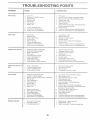
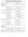
PROBLEM
W_J|not Start
Ha_d _o a_ar_
Engine wI{Inot _tum over
Engine
_ta_
e#¢ks but writ mot
Loss of power
CAUSE
1
Oat of tue.
2
3
4
5_
6
7,
Engine net 'CHOKED"
Engine fooded_
Bad spark peg_
Didy a_r fiter
Drtyf_e liter.
Water is fuei
vibration
propedy
1
Ftl fi.;e ark.
2.
3.
4
5
6.
7
See 'tO START NG{NE'
in Operation section
War severn minutes before atlemphng to start
Rap ace spek p_ug
Cea[Frepaee
a}r fter
Repass fuel f/ter_
Dra}n f_e/lank and cad_uretor rafif tank wit_" freer
gasol ne and replace fl_el fi_ter_
Cheek a_ wi ing_
Contact an authorzed service oenter/_epartment
Contact an auIhorzed service cenler!depadment
8.
9
10
Loose o darnaged wiring
Carbu efer out ol adustmenl
Er gins raves eat of ad ustme_t
8
9.
10.
I.
2
3
4
5
6
7
8
Di_ty air filte_
Badspa_kpug
Weak or dead bal_ery
Dr_y fuel fitter.
Stale or d}f_y fuel
Loose or damaged wineg.
Carburetor out of adiustment
Engine valves out d ed _slmeet
1
2
3
4.
OlearFrep_ec÷ air fte_
Replace spark plug_
Recharge or repla se batleL/_
Replace fee f}!ter.
5.
&
7
8
Dr_n fuei tank and refii/wth fresh gasoline
C_eckal
wrng
Co_tacl an euthohzed sewce eenteddepartment
Contact an nut _o zed sewee center/depadmel
t_
1
2
3
4
C_utsh/Prake peda_ not dep_essed_
Attachment dutch is engaged.
Weak or dead b_teh!
%own fuse
5.
6
7_
8.
9_
Corraded batte_ylermee}s
Loose or damaged wring
Pasty g_iflon swtch
Fauity se}eneid or starter
Faui_y operat/_r presence switch(as}
1.
2.
3
4
!'_
6.
7,
8
g
Depresse!_ehf{}take
peda
Dseagage a_taehment ddLh.
Recharge or _ep_ace bee W
Repines R_se
Cean ballery len ne_s
Checkaif wrin%
ChecW_epiaceignIen
sw}_ch,
C ec!repacesobnodorstarter
Ce_}tac_ an author}zed servce eenteddepartn
1
2.
3.
4
Weak or dead ba_sery.
Co,reded bakery termna!s.
Loose or damaged wring
Fauty solenoid o starter
1
2.
3.
4.
Rechag
or r_p/aee battery
Clean baits 9 term _a_s
Cfeeka
w_r ig
ChecW_ep}aea s-_eneid or etader
1
2_
3.
4
5
6
7.
8
g.
Cull ng tcx) much grass/too fast
Thretfle in "CHOKE" p_asitor_
Ba#d up of grass _eaves and reeh under rrower.
Di_y ar flter
Lrx_ oi bvei/d_y o_
Faulty spark pfu%
Ddyfl_af fi!te_
State st dirty fuel
Water in fuel.
1,
2_
3
4.
5.
6.
7
8.
9.
Set n Higi_e Cul'_post_on/redase
spas&
Adiust throttle centre
Clean _nderside ofmower housing.
CeerJrep_ac_ ar f_er
Check oi_ tarsi/change o
Cear_ and regap or change spark ptug_
Rap!ace fuel flter.
Dra_e fuel tank ard refiit w_h fresh gasoline
O_sai[ rue! tank and carburetor, refill tank with fish
ga_:_o_ineand repines f_._e_
Hter
Cot nest and tighten spark pug wire
Cean engine air screen/lies.
C_ean/replace muff er_
I0
1i.
12
13
I4.
I5.
Excessive
CORRECTION
Spark pk_g wre toese.
Dirty engine air screen/fins
Di£yielogged muffler.
Loose or deranged wring.
Carburetor auf of adiustment.
Engine valves out of adiustment.
10
1
12
13
I4
Check all wfdn#_
Contact an authorized service ce_feddepadmer_t.
Cer_tael an authorized service center/depa_meet.
1_
2.
Worn bent or _oose Made
Bent blade mandrel
'1_ Replace blade. Tighten biade her
2_ Repines blade ma_det,
3
Loose/damaged
3
pad(s},
ant.
Tghten
loo!_e pari(s}_ Repass
damaged
pade_
PROBLEM
CAUSE
Engine centia_es to run
when operator _eaves seat
with attachment clutch
1,
Fairy
1
2
eperater-szfety
press_'oe coat otsystem
t,
Ch_ck wirir _ swtches aed conr_eations_ If not
corrected sea,act an euthor zed service canted
dsparlment
Worn bent or koss blade.
Mower deck not _evs
1
2.
Replace biade Tghten
Levai mower deck
3.
4
Buildup of grass leaves, arid fra_h under mower
Bent blade ma'_drs.
3,
4,
Ciean unde;s}ds of mows
Replace blade mandrel
5.
C_ogged mower deck vent ho_es from buiidup of
grass _aaves and trash around msrsdre s
5
Ciean around mandre s to open venf ho_ss
t
2
Remove obstruct oe
Replace mower drive belt
3.
4_
Replace idler puey,
Replace blade man#eL
engaged
Poo_utouneeen
Mower blades wfli net
rotate
biade bet.
houssg
1
Obsbuetic¢_ r_ clutch mecha_ism
2
3
4
Were/damaged mower drive bet
Frozen id!er p Iley.
Frozen blade mendeL
1
2
3,
4
Engine speed too stow
Traw;_ speed toe fast
Wetgraee
Mower deck not [eve_
1,
2
3,
4.
Place throttle centrei
"FAST' pasties.
Shft to slower speed
Alk_w grass to dry betsre mowing,
Levelmower deck
5
6,
t ow/ur_even tre air pressure.
Worn bent or loose bade_
5
Cheek ires for p 'spar a_' press re.
7.
8
Bi idup d gass, leaves and trash under mower
Mower drve bet worn
6.
7_
&
Replaee/sharpe_ bade. Tighten bade bet.
C_san underside ef mower housng,
Rep_acemewe
ddvs bet
9
10,
1 'i
Blades improperly installed.
Improper b_adestsed
Ciogged mower :tack vent hoes fen buildup of
g_ss
eaves, and trash around rnan@e_s.
9
10,
11.
t.
2
3
Switch s OFF"
Bulb(s} burned out
Faulty lght swtch
4.
5
Raisers i bades sharp edge down.
Rap ace wth blades tared n ths menus,
Clean around mandre s to open vent holes
Loose or damaged wrng_
Blown fuse.
1.
2.
&
4.
5
Tern swtch'*ON'.
Replace hub(s}
ChecWrepaee _ght switch
Check wrng and cenneetons
Repfaee fee
1
2
Bad belts W ca(s}
Poet' cable cannectiene_
f
2
Replace baftery
Cheek/s_e_n a_ connect ons
3.
4
Faulty regulate_ (if so equipped)
Yauty a_f®m tar
3
4.
Replace r®_._u_eteL
Replace e_terlater
1,
M )t_en control ever is o_t of adjustmer_t
1.
Adiust motion centre
Lose of drive
1
2.
3.
Freewheel control in 'd sengeged _posit on.
Moron d_ve belt has worn damaged or broken
Air trapped in transmission dudsg shpment
or sew sing
!
2
3
Place ffeewk eel centre!
engaged'
Replace moron eve belt
Purge transm ss_on
Eng_ee 'backfires _'
when turning engine
'OFF'
t
Engine throttle eontre_ not sat at "SLOW _'
1,
M:>va fhrett e control t( *S£ OW' position and aliow
to ida for 30 seconds before stepping engine,
Trecter"¢taeps_wi_h
met_on sont_offeser
fn
position for 30 seeo -_dsbefore stopping sng se.
Iever.
pesif en
CE
SUGGESTED
GUIDE FOR SiGHTiNG
SLOPES
FOR SAFE OPERATION
ONLY RiDE UP AND DOWN HILL,
NOT ACROSS HiLL
GUIDE
SIGHT AND HOLD THIS
SKY LiNE OR TREE.
LEVEL
WITH
MANUAL
MODEL NO.
917o257590
15.0 HP
ELECTRIC START
42" MOWER
AUTOMATIC (HYDROSTATIC}
DRIVE
LAWN TRACTOR
Each tractor has its own model number.
its own model number.
Each engine has
The reodei number for your tractor wili be found on the
model plate located under the seat,
The model number for your engine wit! be found on the
blower housing of the engine.
iF YOU NEED
REPAIR SERVWCE
OR PARTS:
FOR REPAIR SERVICE, CALL
THIS TOLL FREE NUMBER:
Ail parts listed herein may be ordered from any Sears,
Roebuck and Co, Sewice Center/Depa£ment and most Re_.
tail Stores
WHEN ORDERING REPAIR PARTS, ALWAYS
FOLLOWING INFORMATION:
GLOVE
THE
PRODUCT - TRACTOR
MODEL NUMBER - 917.257590
ENGINE MODEL NO, - 28N7_7o0121 01
FOR REPLACEMENT
PARTS
INFORMATION
AND
ORDERING, GALL THiS
TOLL FREE NUMBER:
* PART NUMBER
'_ PART DESCRiPTiON
Your Sears merchandise has added value when you
consider Sears has service units nationwide staffed with
Sears trained technicians°_
professional
technicians
specificaiiy trained to insure that we meet oar p_edge to
you, we sewice what we sell.
144617
032594
Printed in US.A.