1
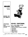
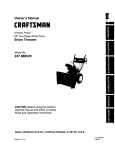
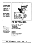
Owner's Manual
5.0 Horse Power
24" Two-Stage Wheel Drive
Snow Thrower
Model No.
247.886640
CAUTION: Before
using this product,
read this manual and
follow all safety rules
and operating
instructions.
•
•
•
•
•
•
Safety
Assembly
Operation
Service
Maintenance
EspaSol
Sears, Roebuck And Co., Hoffman Estates, IL 60179, U.S.A.
Visit our website: www.sears.com/craffsman
PRINTED IN U.S.A.
FORM NO.770-10433
(8/2ooo)
Content
Page
Content
Page
Warranty Information ......................................... 2
Service & Adjustment......................................... 15
Safe Operation Practices ................................... 3
Off-Season Storage ........................................... 19
Hardware Pack ..................................................
5
Trouble-Shooting ............................................... 20
Assembly ...........................................................
6
Parts List ............................................................
21
Operation ...........................................................
10
Espanol ..............................................................
34
Maintenance ......................................................
t3
Two -Year Warranty on Craftsman Snow Thrower
For two years from the date of purchase, when this Craftsman Snow Thrower is maintained, lubricated and tuned
up according to the instructions in the owner's manual, Sears will repair, free of charge, any defect in material
and workmanship.
If this Craftsman snow thrower is used for commercial or rental purposes, this warranty applies for only 30 days
from the date of purchase.
Thls warranty does not cover:
Expendable items which become worn during normal use, such as skid shoes, shave plate and spark
plugs.
Repairs necessary because of operator abuse or negligence, including bent crankshafts and the failure to
maintain the equipment according to the instructions contained in the owner's manual
WARRANTY SERVICE IS AVAILABLE BY RETURNING THE CRAFTSMAN SNOW THROWER TO THE NEAREST
SEARS SERVICE CENTER/DEPARTMENT IN THE UNITED STATES.
Thls warranty applies only while this product Is In use In the United States.
This warranty gives you specific legalrights and you may also have other dghts which may vary from state to state.
SEARS, ROEBUCK AND CO., D/817WA, HOFFMAN ESTATES, IL 60179
Horsepower: ......................... 5.0
Model Number
247.886640
Serial Number ...........................................................
Date of Purchase ......................................................
Record both serial number and date of purchase and
keep in a safe place for future reference.
Engine Oil ............................. SAE 5W30 oil
Spark Plug: ........................... RJ-19LM
Engine: ..................................
143.015007
2
This symbolpoints out important safety instructionswhich, if not followed, could endanger the personal
safety and/or property of yourself and others. Read and follow all instructions in this manual before
attempting to operate this machine. Failure to comply with these instructions may result in personal
injury. When you see this symbol--heed its warning.
A
WARNING:
Engine Exhaust, some of itsconstituents, and certain vehicle components contain or emit
chemicals known to State of Californiato cause cancer and birth defects or other reproductiveharm.
DANGER: This machine was built to be operated according to the rules for safe operation in this
I
manual. As with any type of power equipment, carelessness or error on the part of the operator can resultI
in serious
injury.
This machine
is capable of amputating
hands and
feet and
throwing objects. Failure to
observe
the
following
safety instructionscould
resultin serious
injuryor
death.
Training
1.
2.
3.
4.
5.
6.
7.
Read, understand, and follow all instructionson the
machine and in the manual(s) before attempting to
assemble and operate. Keep this manual in a safe place
for future and regular reference and for ordering
replacement parts.
Be familiar with all controls and their proper operation.
Know how to stop the machine and disengage them
quickly.
Never allow children under 14 years old to operate this
machine. Children 14 years old and over shouldread and
understand the operation instructions and safety rules in
this manual and should be trained and supervised by a
parent.
Never allow adults to operate this machine without
proper instruction.
Thrown objects can cause serious personal injury. Plan
your snow throwing pattern to avoid discharge of material
toward roads, bystanders and the like.
Keep bystanders, helpers, pets and children at least 75
feet from the machine while it is in operation. Stop
machine if anyone enters the area.
Exercise caution to avoid slippingor falling, especially
when operating in reverse.
8.
9.
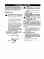
Preparation
1.
2.
3.
4.
5.
6.
7.
Thoroughly inspect the area where the equipment is to
be used. Remove all door mats, newspapers, sleds,
boards, wires and other foreign objects which could be
tripped over or thrown by the auger/impeller.
Always wear safety glasses or eye shields during
operation and while performing an adjustment or repairto
protect your eyes. Thrown objects which ricochet can
cause serious injuryto the eyes.
Do not operate without wearing adequate winter outer
garments. Do not wear jewelry, long scarves or other
loose clothing which coutd become entangled in moving
parts. Wear footwear which will improve footing on
slippery surfaces.
Use a grounded three wire extension cord and receptacle
for all units with electric start engines.
Adjust collector housing height to clear gravel or crushed
rock surfaces.
Disengage all clutch levers before starting the engine.
Never attempt to make any adjustments while engine is
running, except where specifically recommended in the
operator's manual.
Let engine and machine adjust to outdoortemperature
before stading to clear snow.
To avoid personal injuryor propertydamage use extreme
care in handling gasoline. Gasoline is extremely
flammable and the vapors are explosive. Serious
personal injurycan occur when gasoline is spilledon
yourself or your clothes which can ignite. Wash your skin
and change clothes immediately.
a. Use only an approved gasoline container.
b. Extinguish all cigarettes, cigars, pipes and other
sources of ignition.
c. Neverfuel machine indoors.
d. Never remove gas cap or add fuel while the
engine is hot or running.
e. Allow engine to cool at least two minutes before
refueling and at least 5 minutes before storing.
f.
Never over fill fuel tank. Fill tank to no more than
1,6inch below bottom of filler neck to provide space
for fuel expansion.
g. Replace gasoline cap and tighten securely.
h. If gasoline is spilled, wipe it off the engine and
equipment. Move machine to another area. Wait 5
minutes before starting the engine.
i.
Never store the machine or fuel container inside
where there is an open flame, spark or pilot light
(e.g. furnace, water heater, space heater, clothes
dryer etc).
Operation
1.
2.
3.
4.
5.
Do not put hands or feet near rotating parts, in the auger/
impeller housing or discharge chute. Contact with the
rotating parts can amputate hands and feet.
The auger/impeller clutch lever is a safety device, Never
bypass itsoperation. Doing so, makes the machine
unsafe and may cause personal injury.
The clutch levers must operate easily in both directions
and automatically return to the disengaged position when
released.
Never operate with a missing or damaged discharge
chute. Keep all safety devices in place and working.
Never run an engine indoors or in a poorly ventilated
area. Engine exhaust contains carbon monoxide, an
odorless and deadly gas.
6. Donot operate
Maintenance
7.
1.
8.
9.
tO.
t 1.
12.
13.
14.
15.
16.
17.
18.
19.
20.
machine while under the influence of
alcohol or drugs.
Muffler and engine become hot and can cause a burn. Do
nottouch.
Exercise extreme caution when operating on or crossing
gravel surfaces. Stay alert for hidden hazards or traffic.
Exercise caution when changing direction and while
operating on slopes.
Plan your snow throwing pattern to avoid discharge
towards windows, walls, cars etc. To avoid property
damage or personal injury caused by a ricochet.
Never direct discharge at children, bystanders and pets
or allow anyone in frontof the machine.
Do not overload machine capacity by attempting to clear
snow at too fast of a rate.
Never operate thismachine without good visibilityor
light. Always be sure of your footing and keep a firm hold
on the handles. Walk, never run.
Disengage power to the auger/impeller when
transporting or not in use.
Never operate machine at high transport speeds on
slippery surfaces. Look down and behind and use care
when in reverse.
If the machine shouldstart to vibrate abnormally, stop the
engine, disconnect the spark plug and ground it against
the engine. Inspect thoroughly for damage. Repair any
damage before startingand operating.
Disengage all clutch levers and stop engine before you
leave the operating position (behind the handles). Wait
until the auger/impeller comes to a complete stop before
unclogging the discharge chute, making any
adjustments, or inspections.
Never put your hand in the discharge or collector
openings. Always use a clearing tool to unclogthe
discharge opening.
Use only attachments and accessories apprcved by the
manufacturer (e.g. wheel weights, tire chains, cabs etc.).
If situabons occur which are not covered in thismanual,
use care and goodjudgment. Contact your nearest Sears
service center for assistance.
and Storage
Never tamper with safety devices. Check their proper
operation regularly.
2. Disengage all clutch levers and stop engine. Wait until
the auger/impeller come to a complete stop. Disconnect
the spark plug wire and ground against the engine to
prevent unintended startingbefore cleaning, repairing,or
inspecting.
3. Check bolts, and screws for propertightness at frequent
intervals to keep the machine in safe working condition,
Also, visually inspect machine for any damage.
4. Do not change the engine governor settingor over-speed
the engine. The governor controlsthe maximum safe
operating speed of the engine.
5. Snow thrower shave plates and skid shoes are subject to
wear and damage. For your safety protection,frequently
check all components and replace with original
equipment manufacturer's (O.EM.) parts only. "Use of
parts which do not meet the original equipment
specifications may lead to improper performance and
compromise safety!"
6. Check clutch controls periodicallyto verify they engage
and disengage properly and adjust, if necessary. Refer to
the adjustment section in thisoperator's manual for
instructions.
7. Maintain or replace safety and instructionlabels, as
necessary.
8, Observe proper disposal laws and regulations for gas,
oil, etc. to protect the environment.
9. Prior to storing, run machine a few minutes to clear snow
from machine and prevent freeze up of auger/impeller.
tO. Never store the machine or fuel container inside where
there is an open flame, spark or pilot lightsuch as a water
heater, furnace ,clothesdryer etc.
11. Always refer to the operator's manual for praper
instructionson off-season storage.
Your Responsibility:
Restnct the use of this power machine to persons who read,
understand and follow the warnings and instructionsin this
manual and on the machine. The most important safety labels
are reproduced below. For a detailed labels map, see
Parts List section.
1.BENP
AWAYEROM
ROTATING
IMPeJ,.ER
ANDS.
€_OT'_TEREH
ENPELL_
ER
ACRER
CANAMPUTATE
laNDSAHDFEET.
E.DISENGAGE
CLUTCH
LEVER|.
STOP
ENGINE.
ANDPJUIAIH
IERIIiRHANOLEN
6RILLALL
MOERi6
PARTS
HAVEOTOPPEO
BEFORE
UNCLOG61i46
ORSERVICING
MACHINE.
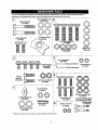
Lay outthe hardware according to the illustrationbelow for identificationpurposes. Part numbers are shown in
parentheses. (Hardware pack may contain extra items which are not used on your unit.)
A!_
(4)Lock Washers (C)
(736-0119)
(2)Hex Bolts (A)
I:_
©
©©
©©
(710-3180)
1111111111111111111111
IIIIIIIIII11i1111111II
12) Handle Tabs 11)
(2) Hex Bolts(B)
710-3008
(4) Carriage Bolts (E)
(710-0262)
G g,G
Washers (C)
(736-0119)
(7,,-'0'7%_
_")
(2) Hex Nuts (J)
___
_
(2)Hex
Screws (F)
t_l
_
_.
..............................
88
@11t11111111111!111
(712-3015)
Belle(G)_lllllllllllllllll]
@
Cupped Washer (N)
(736°0242)
Q©
(712-0121 )
FlO-O509)
oo
(2) Hex Nuts (D)
(712-3010)
©©
Hairpin Clip IT)
(714-0104)
(2) Flat Washers IS)
(736-0185)
" Replacement hardware only; not required in initial assembly of the snow thrower.
(6) He(_1L_.c,
k2N;_ts (M)
(6) Hex Bolts (K)
(710-3015)
(3) Chute Flange Keepers
(Not Shown) (731-0051)
(2) Shear Bolts
(710-0890A)
(2) Hex Lock Nuts
(7120429)
L..._r
@@
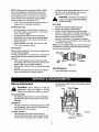
NOTE: References to right or left side of the snow
thrower are determined from behind the unit in the
operatingposition.
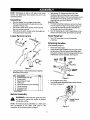
Unpacking
Remove staples from top flaps of the carton.
Remove any loose parts included with unit (i.e.,
operator's manual, etc.).
Cut corners of the carton and lay ends down fiat,
Remove packing material.
Roll unit out of carton. Check carton thoroughly for
loose parts before discarding.
•
•
Take the two "Z" fittings from Group D of the
Hardware Pack and insert the Z end ofthese
throughthe two holes on the two clutchgrips on the
handle panel. The handle panel was shipped as
loose part with your snow thrower.
Assembly Tips:
1. For easier assembly purposes, remove the chute
from the carton and lay it on top of the engine, Do
not unwrap the chute till you have installed the
handle panel and the clutch cables.
2. Lookfor stampinge of L and R respectivelyon the
bottom of the left and the right handles to identify.
Tools Required
Loose Parts In Carton
1. Two 7/16" wrenches or a set of adjustable
wrenches.
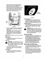
Attaching Handles
(Use hardware group B,)
•
•
Raise beth clutch grips,
Lower left and right handles down through handle
panel between the pivot rod and the clutch grips
and attach using two each of carriage bolts (E), lock
washers (C) and hex nuts (D). See Figure 2.
_andle Clutch •
Left Handle
_1I'.._
Pivot Rod
Figure 1
•
Compare Figure 1 with the list below to identify
loose parts in the carton.
Ref.
A
B
Description
Handles (Right and Left)
Handle Panel
Qty.
2
1
C
D
E
Speed Selector Plate
Shift Lever
Chute Directional Control Assembl
1
1
1
F
G
H
3hute Assembly
Hardware Pack*
Extension Cord
1
1
1
_//
" Lock
//
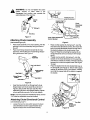
Figure 2
•
•
Do nottighten at this time.
Lay handle panel assembly behind snow thrower
as shown in Figure 3,
• S_own on page 5
Before Assembly
Handle Panel &
Handles
and ground it Disconnect
WARNING:
against the the
engine
sparktoplug
prevent
wire
unintended starting.
NOTE: All hardware pieces identified by a letter code
here correspond to the letter code used in the
descriptionof the hardware pack on page 5.
Figure 3
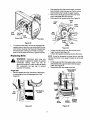
(Usehardware group A.)
Attaching Shift Lever
•
(Use hardware group C.)
Insert one each of hex bolt (B) and lock washer (C),
from Group A of the hardware pack, through the
bottomhole in left handle and corresponding hole
in snow thrower housing. See Figure 4. Do not
tighten. Repeat on the other side.
Raise both handles up until the upper hole in each
handle align with lhe upper hole on each side of the
snow thrower housing. Secure with hex bolt (A),
lock washer (C) and handle tab (I) on each side.
See Figure 4,
•
Insert the shift lever through slot in the speed
selector plate. See Figure 6. The bend in the lever
shouldbe towards the operator.
Left Handle
\
Plate
PlexLock Nuts H
Tab I
Washer C
Shift Lever
Spring
Hex
Bolt A
Figure 6
Hex
Secure shift lever to the shift lever spring using two
hex bolts (G) and hex lock nuts (H). See Figure 6.
Tighten both bolts finger tight. At this point the shift
lever and shift lever spring are not against each
other. As you tighten the bolts and nuts with two
wrenches, these will pull together.
Tighten all hardware assembled to this point. Make
sure that clutch grips are moving freely.
Bolt B
Figure 4
Attaching Speed Selector Plate
(Use hardware group C.)
•
Assemble the speed selector plate to the outside
of the handles as shown in Figure 5. Secure using
two self-tapping screws (F) from hardware group C,
Repeat on the other side.
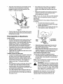
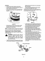
Attaching Control Cables
(Use hardware group D.)
•
Self-Tapping
Screws F
Self-Tapping
Screws F
Since the Z fittingis already inserted into the hole
on the clutch grip at this point, thread a hex nut (J)
from hardware pack D on to each Z fitting. See
Figure 7.
Route the left cable between engine and speed
selector plate and then between handle panel and
clutch lever pivotrod. Thread cable onto the left
"Z" fitting.
Assemble the right cable in the same manner.
Both cables should have minimal slack, but not
tight. Tighten or loosen hex nuts on the "Z" fitting to
adjust.
IMPORTANT:If the righthand lock-out cable is not
adjusted correctly,the wheels will tend to turn. If the left
hand lock-out cable is not adjusted correctly,the
augers will keep on rotating.
NOTE: Thedriveclutchcab/eisroutedovertheaxle.
Figure 5
A
WARNING:
Do not over-tighten the clutch
cables. Tension on either cable in the
disengaged (up) position may override the
safety features of the machine.
_
Loosen hex nuts
under this bracket
Clutch
Grip
Hairpin Clip T &
Flat Washer S
Chute
Directional
Control
Hex Nut J
Figure 7
Control Bracket
Attaching Chute Assembly
(Use hardware group E,)
•
•
Figure 9
Race chute assembly over chute opening, with the
opening in the chute assembly facing the front of
the unit,
Place chute flange keepers beneath lip of chute
assembly, with the flat side of chute flange keeper
facing downward, See Figure 8.
Place one flat washer (S), from group F, over the
end of the chute directional control, then insert the
end of the chute directional control into the hole in
the plastic bushing on the chute bracket. See
Figure 9. Place the remaining flat washer (S) on
chute directional control, and secure with hairpin
clip (T).
Thread one hex nut (D), from group F, onto the
eyebolt on the chute directional control assembly
until there is at least two inches of threads showing
between the nut and the eyeboit head. See Figure
10 inset.
Chute
Y
Place the eyebolt intothe hole located half way up
the left handle. See Figure 10. Secure with cupped
washer (N) and hex nut (D), from group F, making
sure that the cupped side of the washer is against
the handle.
Hex Bolt K_
Cl_ute Flange -----_
r_eeper
Figure 8
Insert two hex bolts (K) up through each chute
flange keeper and chute assembly as shown in
Figure 8. Secure with hex lock nuts (M). After
assembling all three chute flange keepers, tighten
all nuts and bolts securely. Do not over-tighten.
NOTE: Lock nuts cannot be threaded by hand; use two
7/16" sized or adjustable wrenches instead.
Attaching Chute Directional Control
(Use hardware group F.)
•
Loosen the two hex nuts which secure the lower
chute directionalcontrol supportbracket (see
Figure 9 inset) to the snow thrower housing,
e Bolt
Directional
Control
Figure 10
8
Adjust the chute directional control bracket so that
the spiral on the chute directional control fully
engages the teeth on the chute assembly. See
Figure 11. Tighten all hardware.
•
•
If the wheels do not stop when you engage the
traction control grip, loosen the jam nut on the
traction control cable and thread the cable in one
turn.
Recheck the adjustment and repeat as necessary.
Tighten the jam nut to secure the cable when
correct adjustment is reached.
NOTE: If you are not sure that you have adjusted
correctly, refer to the Adjustment section on page 15.
Skid Shoes
The space between the shave plate and the ground can
be adjusted.
a. For close snow removal on a smooth
surface, raise skid shoes higher on the auger
housing. See Figure 12.
b. Use a middle or lower position when the area
to be cleared is uneven. See Figure 12.
_ira[should engage
teeth of chute here
Figure 11
Check to make sure all nuts and bolts on the control
panel and all four boltswhich secure the handles to
the frame are very tight.
Final Assembly & Adjustments
Auger Control
•
To check the adjustment of the auger control, push
forward on the left hand clutchgrip (depress the
rubber bumper). There should be slack in the cable.
Release the clutchgrip. The cabte shouldbe
straight. Make certain you can depress the auger
controlgrip against the left handle completely.
•
Ifnecessary, loosen the hex lock nut and thread the
cable in (for less slack) or out (for more slack) as
necessary. Refer to Figure7.
•
Tighten the lock nut against the cable when correct
adjustment is reached.
Traction
Control
oe
•
•
Hex Nuts
CarriageBolts
Figure 12
tr-
Adjust skid shoes by loosening the four hex nuts
and carriage bolts as shown in Figure 12. Move
skid shoes to desired position.
Make certain the entire bottom surface of skid shoe
is against the ground to avoid uneven wear on the
skid shoes. Retighten nuts and bolts securely.
Tire Pressure (Pneumatic Tires)
The tires are overinflated for shipping purposes.
& Shift Lever
To check the adjustment of the traction control and
shift lever, move the shift lever all the way to the
right to fifth (5) position. With the traction control
released, push the snow thrower forward. The unit
should move forward freely. Then engage the
traction control grip. The wheels should stop
turning.
Now release the traction control grip, and push the
unit again. Move the shift lever back to the fast
reverse position, then all the way forward again.
There should be no resistance in the shift lever, and
the wheels should keep turning.
If you feel resistance when moving the shift lever or
the wheels stop when they should not, loosen the
jam nut on the traction control cable and unthread
the cable one turn.
•
Check tire pressure. Maintain pressure between 15
to 20 psi. Refer to tire sidewalls for recommended
tire pressure.
NOTE: If the tire pressure is not equal in both tires, the
unitmay puff to one side or the other.
A
WARNING:
Maximum tire pressure under
any circumstance is 30 psi. Equal tire pressure
should be maintained at all times. Excessive
pressure (over 30 psi) when seating beads
may cause tire/rim assembly to burst with
force sufficient to cause serious injury.
IMPORTANT:After assembly, service engine with
gasoline, and check oillevel as instructedin the
separate engine manual packed with your unit.
9
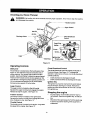
Knowing your Snow Thrower
,_
WARNING:
familiar
with all the controlsand their proper operation. Know how to stop the machine
and disengage Be
them
quickly.
•,
--Traction
b_
Control
Auger Control
Shift Lever
Gas Fill
Discharge Chute
\
Chute Directional
Control
---
Spark Plug _
_
1
/
Auger
Ignition Key___X
|
Skid Shoe
Throttle Le_er
"_
Recoil Starter_
Figure 13
Operating Controls
Chute Directional
Shift Lever
The chute directional controlis located on left side of
the snow thrower. See Figure 13. To change the
direction in which snow is thrown, turn chute directional
control as follows:
The shiftlever is located below the handle panel. See
Figure 13. The shift lever may be moved into one of
seven positions.Run engine with throttle in the fast
position.Use the shift lever to determine ground speed.
There are five forward and two reverse speeds on this
snowthrower. Among the forward speeds, positionone
(1) isthe slowest and position five (5) is the fastest.
Among reverse speeds, R2 is the faster.
•
•
Crank clockwise to discharge to the left.
Crank counterclockwise to discharge to the right.
Ignition Key
The ignitionkey must be inserted in the switch before
the unit willstart. See Figure 13 inset. Remove the
ignition kay when snow thrower is not in use. Do not
turn ignitionkey.
Auger Control
The auger control is located on the left handle.
Squeeze the auger controlgrip to engage the augers.
Release to stop the augers. See Figure 13.
Traction
Control
Stopping the engine
Control
•
The traction controlis located on the right handle.
Squeeze the traction control grip to engage the wheel
drive. Release to stop. See Figure 13.
•
Throttle Control
The throttle controlis located on the engine. It regulates
the speed of the engine. See Figure 13.
10
To stop engine, move throttle controlto "stop" or
"off" position.Remove the ignitionkey. Do not turn
key.
Disconnect the spark plug wire from the spark plug
to prevent accidental starting while equipment is
unattended.
Before Starting
and carburetorare empty. Use fresh fuel nextseason.
See storage Instructions for additionalinformation.
Never use engine or carburetor cleaner products in the
fuel tank or permanent damage may occur.
WARNING:
Read,warnings
understand,
and
follow
all instructions and
on the
machine
and in this manual before operating.
•
•
•
To Start Engine
The engine was shipped with oil. Check the oil level
before operating. After the initial use, you will have
to fill up as necessary. Be careful not to overfill.
Before filling up gas in the engine for the first time,
open the gas tank cap, and locate a white plastic
cap underneath. Remove this cap and discard it.
The spark plug wire was disconnected for safety.
Attach spark plug wire to spark plug before starting.
•
Attach spark plug wire to spark plug. Make certain
the metal loop on the end of the spark plug wire
(inside the boot) is fastened securely over the metal
tip on the spark plug. See Figure 14.
Before Starting Engine
Fill Gas
&
WARNING: Gasoline is flammableand caution must be used when handlingor storing it.
Figure 14
Make certain the auger and drive clutch levers are
in the disengaged (released) position.
Move throttle control up to FAST position. Insert
ignition key into slot. Make sure it snaps into place.
Do not turn key.
Do not fill fuel tank while the snow thrower is
running, when it is hot or when it is in an
enclosed area.
Keep your snow thrower away from any open
flame or an electrical spark and do not smoke
while filling the fuel tank.
NOTE: Engine will not start unless ignition key is
inserted into ignitionslot in carburetor cover.
Never fill the fuel tank completely. Fill the tank
to within 1/4"-1/2" from the top to provide
space for expansion of fuel.
Electric Starter
WARNING:
The electric starter is equipped
with a grounded throe-wire power cord and
plug, and is designed to operate on 120 volt
AC household current. It must be used with a
properly grounded three-prong receptacle at
all times to avoid the possibility of electric
shock. Follow all instructionscarefully prior to
operating the electric starter.
Always fill the fuel tank outdoors and use a
funnel or spout to prevent spilling.
Make sure to wipe off any spilled fuel before
starting the engine.
•
•
•
Store gasoline in a clean, approved containerand
keep the cap in place on the container.
Make sure that the container from which you pour
the gasoline is clean and free from rust or other
foreignparticles.
Fillfuel tank with clean, fresh, unleaded grade
automotive gasoline.
At the end of the job, empty the fuel tank ifthe
snowthrower is not going to be used for 30 days
or longer. See storage instructionson page 19 of
this manual.
Determine that your house widng is a three-wire
grounded system. Ask a licensed electrician if you
are not certain.
If your house wiring system Is not a three-wire
grounded system, do not use this electricstarter
under any conditions.
If your home electrical system is grounded, but
a three-hole receptacle is not available, one should
be installed by a licensed electricianbefore using
the electric starter.
CAUTION: Experience indicates that alcohol blended
fuels (called gasohol) or those using ethanol or methanol can attract moisture which leads to separation and
formation of acids during storage.
If you have a grounded three-prong receptacle,
proceed as follows.
Rotate choke knob to OFF position.
Connect power cord to switch box on engine. Plug
the other end of power cord intoa three-prong 120volt, grounded, AC receptacle.
Push starter button to crank engine. As you crank
the engine, move choke knob to FULL choke
position,
Acidic gas can damage the fuel system of an engine
while in storage.
To avoid engine problems, the fuel system should be
emptied before storage for 30 days or longer. Drain the
gas tank, start the engine and let it run until the fuel lines
11
When engine starts, release starter button, and
move choke gradually to OFF. If engine falters,
move choke immediately to FULL and then
gradually to OFF.
When disconnecting the power cord, always unplug
from the three-prong receptacle first, and then from
the snow thrower.
push starter button and spin the starter for several
seconds. The unusual sound made by spinning the
starter will not harm engine or starter. Disconnect
the power cord from receptacle first, and then from
switch box.
Recoil Starter
•
Recoil Starter
•
•
•
•
Rotate choke knob to FULL choke position (cold
engine start).
If engine is warm, place choke in OFF position
instead of FULL.
Push primer button two or three times for cold
engine start.
If engine is warm, push primer button only once.
•
•
With engine running, pull starter rope with a rapid,
continuous full arm stroke three or four times.
Pulling the starter rope will produce a loud clattering
sound, which is not harmful to engine or starter.
To stop engine, move throttle control to "stop" or
"off" position.
Remove the ignitionkey. Do not turn key.
Disconnect the spark plug wire from the spark plug
to prevent accidental starting while equipment is
unattended.
NOTE: Always cover vent hole in primer button when
pushing. Additional priming may be necessary for first
start if temperature is below 15 degrees Fahrenheit.
NOTE: Do not lose ignition key. Keep it in a safe place.
Engine will not start without the ignition key.
•
•
•
•
Grasp starter handle and pull rope out slowly, until
it pulls slightlyharder. Let rope rewind slowly.
Pull starter handle rapidly. Do not allow handle to
snap back. Allow it to rewind slowly while keeping a
firm hold on the starter handle.
As engine warms up and begins to operate evenly,
rotate choke knob slowly to OFF position. If engine
falters, return to FULL choke, then slowly move to
OFF position.
To Engage Drive
•
To Stop Engine
•
Run engine for a few minutes before stopping to
help dry off any moisture on the engine.
To help prevent possible freeze-up of starter,
proceed as follows.
•
•
Electric Starter
•
Wipe all snow and moisture from the carburetor
cover in the area of the control levers. Also, move
control levers back and forth several times.
Connect power cord to switch box on engine, then
to 120 volt AC receptacle. With the engine running,
With the engine running near top speed, move shift
lever intoone of the five FORWARD positionsor
two REVERSE positions. Select a speed
appropriatefor the snow conditionsthat exist. Use
the slower speeds until you are familiar with the
operationof the snow thrower.
Squeeze the auger control grip and the augers will
turn. Release it and the augers will stop.
Squeeze tractioncontrol grip and the snow thrower
willmove. Release it and drive motion willstop.
NEVER move shift lever without releasing drive
clutch.
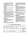
Starting Instructions
Drive
Levers
Snow
Thrower
Spark
Plug
wire
Electric
Starter
Connect Release
Recoil
Starter
Connect Release
At A Glance
,Throttle
control
Ignition
Key
Choke
Power
Co_
Move to
FAST
Push to
snap in
Move to
FULL
Connect
to source
Move to
FAST
Push to
snap in
Move to
FULL
12
Primer
Prime
Starter
After starting
Push
button
1. Release button
2. Move Choke to
Off
3. Disconnect
cord
Pull
handle
1. Release handle
2. Move Choke to
Off.
•
To Engage Augers
•
To engage the augers and start throwing snow,
squeeze the auger controlgrip against the left
handle. Release to stop the augers.
•
•
Operating Tips
•
Allowthe engine to warm up for a few minutesas
the engine will not develop futtpower until it
reaches operating temperature.
•
•
_k
WARNING:
and surrounding
areas become Muffler,
hot andengine
can cause
a burn. Do
not touch.
Tire Chains (ifequipped)
•
General Recommendations
•
For most efficientsnow removal, remove snow
immediately after it falls.
Discharge snow downwind whenever possible.
Slightly overlap each previous swath.
Set the skid shoes 1/4" below the scraper bar for
normal usage. The skid shoes may be adjusted
upward for hard-packed snow. Adjust downward
when using on gravel or crushed rock.
Be certain to follow the precautions listedunder "To
Stop Engine" to prevent possiblefreeze-up.
Clean the snow thrower thoroughly after each use.
Tire chains, if your snow thrower is so equipped,
should be used whenever extra traction is needed.
Some adjustments willhave to be made
periodically to maintain your unit properly.
All adjustments in the Service and Adjustments
section of this manual should be checked at least
once each season.
Follow the maintenance schedule given below.
Periodically check all fasteners and make sure
these are tight.
Always observe safety ruleswhen performingany
maintenance.
The warranty on this snow thrower does not cover
items that have been subjected to operator abuse
or negligence. To receive full value from the
warranty, operator must maintain the snow thrower
as instructed in this manual.
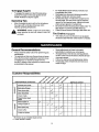
Customer Responsibilities
MAINTENANCE SCHEDULE
_
v-'_
<_P
Lubricatepivotpoints
(_
Clean snowthrower
8
Clean shaveplate
Clean skidshoes
_
¢
,_
_
'_
_
'_
Check V-belts
Check frictionwheel
rubber
_¢2
Check engineoil
uJ
z
Change engineoil
_
_Z Check spark plug
_
<_
LIJ
Check muffler
Emptyfuel system
,_
• Fill in dates as you complete regular service
Check; service if needed
13
SERVICE DATES*
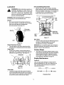
Lubrication
&
WARNING:
Before lubricating, repairing, or
inspecting, disengage all clutch levers and
stop engine. Wait until all moving parts have
come to a complete stop. Disconnect spark
plug wire and ground it against the engine to
prevent unintended starting.
Drive and Shifting Mechanism
•
Remove rear cover. Oil any chains, sprockets,
gears, bearings, shafts, and shiftingmechanism at
least once a season. See Figure 17. Use engine oil
or a spray lubricant. Avoid getting oil on rubber
friction wheel and aluminum drive plate.
iMPORTANT:When lubricating engine or draining oil,
avoid drippingoil onto transmission parts.
Lever
Wheels
Oil or spray lubricant into bearings at wheels at
least once a season. Pull klick pin, remove wheels,
clean and coat axles with a multipurpose
automotive grease. See Figure 15
Oil bearings
' lubricant
KlickPin
\
)n
friction wheel
and drive plate
Lube
Gear
Sha_
Figure 17
Gear Case
•
Figure 15
Chute Directional
•
Control
The worm gear case has been filled with grease at
the factory. If disassembled for any reason,
lubricatewith 2 ounces of shell grease.
iMPORTANT:Do not overfill the gear case. Damage to
the seals could result. Be sure the vent plug is free of
grease in order to relieve pressure.
The worm gear on the chute control should be
lubricated with multipurposeautomotive grease.
Auger Shaft
•
At least once a season, remove shear bolts on
auger shaft. Oil or spray lubricant inside shaft and
lubricatethe auger bearings. See Figure 16.
Friction Wheel
The rubber on the friction wheel is subjectto wear
and should be checked after 25 hours of operation,
and periodically thereafter. Replace the friction
wheel rubber if any signs of wear or cracking are
found following instructions on page 18.
Shear Bolts
Engine Maintenance
Engine Oil
Only use high quality detergent oil rated with API
service classificationSF, SG or SH. Select the oil's
SAE viscosity grade according to the expected
operating temperature.
Bearings
Figure 16
colder _
320 F_
warmer
Gear Shaft
Lubricate the gear shaft with a good all-weather
multi-purpose lightgrease at least once a season or
after every 25 hours of operation. Keep al! grease
and oil oft the friction wheel and drive plate.
5w3o
I
I
Viscosity Chart
14
_
SAE30
NOTE: Althoughmulti-viscosity oils (5W30, 10W30
etc.) improve starting in cold weather, these multiviscosity oils will result in increased oil consumption
when used above 32°F. Check your snow thrower's
engine oil level more frequently to avoid possible
engine damage from running low on oil
Check and make sure that the level of oil is up to
the FULL mark on the dipstick. The oil sump
capacity is 21 ounces or 0.62 liters.
_k
Refer to the viscositychart for proper selectionof
engine oil. Do not use SAE 10W40 oil.
WARNING:
of muffler
and
nearby
areas Temperature
may exceed 150
° F(65°C).
Avoid these areas.
Spark Plug
Checking Oil Level
•
•
Before operating the snow thrower, check the oil
level. With engine on level ground, the oil must be
to FULL mark on dipstick.
Stop engine and wait several minutes before
checking oil level. Remove oil fill cap and dipstick.
Wipe dipstick clean, insert it into oil fill hole and
tighten securely.
Remove dipstick and check. If oil is not up to the
FULL mark on dipstick, add oil.
•
Clean area around the spark plug base.
Remove and inspect the spark plug.
Replace the spark plug if electrodes are pitted,
burned, or the porcelain is cracked. See Figure 18.
Clean the spark plug and reset the gap to 0.030" at
least once a season or every 100 hours of
operation. See Figure 18. Replace if necessary.
For replacement, use Champion J-8C, Autolite 356
or equivalent spark plug.
NOTE: Do not sandblast spark plug. Spark plug should
be cleaned by scraping or wire brushing and washing
with a commercial solvent.
Changing Oil
Change engine oil after first two hours of operation and
every 25 hours thereafter.
In order to change the oil, you will have to first drain the
spent engine oil from the engine and then refill with
fresh oil.
•
•
Drain oil while engine is warm. Remove oil drain
cap located at the bottom of the recoil starter of the
engine. Catch oil in a suitable container.
When engine is drained of all oil, replace drain plug
securely.
Remove the dipstick from the oil fill. Pour fresh oil
slowly through the plug. Replace dipstick.
Gap
Figure 18
Tire Pressure
•
Making Adjustments
,_
Follow instructionson page 9.
snow thrower so that it rests on the auger housing.
See Figure 19.
WARNING:
Nevertheattempt
any
adjustments
while
engineto ismake
running,
except where specified in operator's manual.
Chute Assembly
The distance snow is thrown can be controlledby
adjustingthe angSeof the top section ofthe chute
assembly.
Skid Shoe
•
The space between the shave plate and the ground
can be adjusted. Refer to the Final Assembly and
Adjustments section on page 9.
Traction
Control
Drain gasoline and engine oil from the snow
thrower. Place plastic film under the gas cap if the
snow thrower has already been operated. Tip the
Auger
Housing
Figure
15
19
•
Remove the frame cover underneath the snow
thrower by removing six self-tapping screws. For
locationof the frame cover, see Figure 19.
When the traction control is released, there mustbe
clearance between the friction wheel and the drive
plate in all positions of the shift lever. When the
traction control is engaged, the fdction wheel must
contact the drive plate. See Figure 20.
Hole in Axle
Figure 21
One Wheel Driving
•
On the right side of the unit, place klick pin in the
outside axle hole only. Do not place pin through
wheel hub. This position gives power drive to the
left wheel only, making the uniteasier to maneuver.
Both Wheels Driving
Rotate wheel assembly to align hole in the hub with
the inner hole on the axle shaft. Insert klick pin in
the hole. Outer axle shaft hole should be visible.
See Figure 21.
Figure 20
•
•
If any one of these are not occuring, adjustment is
necessary. Follow the steps below to adjust the
tractioncontrol.
Loosen the lock nut on the traction controlcable
A
and thread the cable in or out as necessary.
Tighten the lock nut to secure the cable when
correct adjustment is reached. Reassemble the
frame cover.
Auger Control
•
To adjust the auger clutch, refer to Final Assembly
and Adjustments on page 9.
Carburetor
•
WARNING:
If any adjustments need to be
made to the engine while the engine is running
(e.g. carburetor), keep clear of all moving
parts. Be careful of muffler, engine and other
surrounding heated surfaces.
The augers are secured to the spiral shaft with two
shear bolts and hex lock nuts.See Figure 16. If you
hit a hard foreign object or ice jam, the snow
thrower is designed so that the bolts may shear.
If the augers will not turn, check to see if the bolts
have sheared. Replacement shear boltsand hex
lock nuts have been provided with the snow
thrower. When replacing bolts, spray an oil
lubricant intoshaft before inserting new bolts.
Shave Plate and Skid Shoes
The shave plate and skid shoes on the bottom of
the snow thrower are subject to wear. They should
be checked periodically and replaced when
necessary.
To remove skid shoes, remove the four carriage
bolts, cupped washers and hex nuts which attach
them to the snow thrower. Reassemble new skid
shoes with the four carriage bolts, cupped washers
(cupped side goes against skid shoes) and hex
nuts. See Figure 22.
Minor carburetor adjustment may be required to
compensate for differences in fuel, temperature,
altitude and load.
Drive Wheels
•
Before servicing, repairing, or
inspecting, disengage all clutch levers and
stop engine. Wait until all moving parts have
come to a complete stop. Disconnect spark
plug wire and ground it against the engine to
prevent unintended starting.
Servicing Augers
NOTE: ff you placed plastic under the gas cap earlier,
remove it now.
A
WARNING:
The wheels may be adjusted for two different
methods of operation. Follow the steps below for
adjustment. See Figure 21.
16
Drain gasoline from the snow thrower, or place a
piece of plastic under the gas cap.Tip the unit up
and forward so that it rests on auger housing.
Remove six self-tapping screws from the frame
cover underneath the snow thrower,
Roll auger belt off engine pulley. See Figure 24.
Auger
Belt
\
L"_
i_ '_
Drive
Belt
r- \_T _i
_;__-_'_,
.
Drive
'
_.
Pulley
Skid
Shoe
Bolts
/_('_l_"_/
/
Figure 22
Pulley / \\ "_
IdI,'
\_L-_ _Pulle
/
To remove shave plate, remove the carriage bolts,
cupped washers and hex nuts which attach it to the
snow thrower housing.See Figure 22. Reassemble
new shave plate, making sure heads of carriage
boltsare to the inside of housing.Tighten securely.
_
Figure 24
•
Replacing Belts
Unhookthe idler springfrom the hex bolt on the
auger housing. See Figure 25.
Unhook the support bracket spring from the frame.
NOTE: It may be necessary to loosen the six nuts that
connect the frame to the auger housing to aid in belt
removal.
WARNING:
Disconnect spark plug wire
and ground it against the engine to prevent
unintended starting. Drain fuel into an
approved container or place a piece of plastic
film underneath the gas cap to prevent
gasoline from leaking.
•
•
Liftthe auger belt from the auger pulley, and slip
belt between the support bracket and the auger
pulley, See Figure 24.
Reassemble with new auger drive belt.
Auger Belt
•
Remove plastic belt cover from front of the engine
by removing the two self-tapping screws. See
Figure23.
Pin
Friction Wheel
Assembly
Gear
Belt
Cover
Screws
Idler
Spring
/
Auger
Housing
Figure 25
Figure 23
17
Drive Belt
•
•
•
tapping screws from the frame cover underneath
the snow thrower.
•
Remove the klick pins which secure the wheels,
and remove the wheels from the axle.
Using a wrench to hold the shaft, loosen, but do not
completely remove, the hex nut and bell washer on the
left end of gear shaft. See Figure 27.
Follow first foursteps of previous instructions.
Pull idler pulley up, and lift belt off engine pulley and
friction wheel disc. See Figure 24.
Using a wrench, loosen the nut on the stop bolt until
the support bracket rests on the auger pulley. See
Figure 26.
Friction
Wheel
\
Uter
Figure 27
Lightly tap the hex nut to dislodge the ball bearing
from the right side of the frame. Remove the hex
nut and bell washer from the left end of the shaft.
Slide the gear shaft to the right, then slide the
friction wheel assembly from the shaft.
Remove the six screws from the friction wheel
assembly (three from each side). See Figure 28.
Remove the friction wheel rubber from between the
friction wheel plate.
Reassemble new friction wheel rubber to the
Figure 26
Slip belt between friction wheel and friction wheel
disc. See Figure 26. Remove and replace belt.
Reassemble in reverse order.
NOTE: The supportbracket must rest on the stop bolt
after the new belt has been assembled. See Figure 26.
Replacing Friction Wheel Rubber
Replace the friction wheel rubber if any signs of wear or
cracking are found.
friction wheel assembly, tightening the six screws in
rotation and with equal force. See Figure 28.
Slide friction wheel assembly back onto the gear
shaft. Be sure to align the pin on the shift rod with
hole in the friction wheel assembly. See Figure 25.
Reassemble gear shaft and the wheels. Reattach
the frame cover. Flip snow thrower back to its
operating position and remove any plastic from
under the machine or around the gas cap if you had
put it earlier.
WARNING:
Disconnect spark plug wire
and ground it against the engine to prevent
unintended starting. Drain fuel into an
approved container or place a piece of plastic
film underneath the gas cap to prevent
gasolinefrom leaking.
Tip the snow thrower up and forward, so that it rests
on the housing.See Figure 19. Remove the six selfScrews
Friction Wheel Rubber
/
Hub
Screws
Friction Wheel
Plates
'_
Figure 28
18
Ifthe snow thrower will not be used for 30 days or
longer, or at the end of the snow season when the tast
possibility of snow is gone, the equipment needs to be
stored properly. Follow storage instructions below to
ensure top performance from the snow thrower for
many more years.
WARNING:
Drain fuel into approved
container outdoors, away from any open
flame. Be certain engine is cool. Do not smoke.
Fuel left in engine during warm weather
deteriorates and will cause serious starting
problems.
Preparing Engine
WARNING:
Run the engine until the fuel tank is empty and it
stops due to lack of fuel.
Drain carburetor by pressing upward on bowl drain,
located below the carburetor cover. See Figure 29.
Never store snow thrower with
fuel in tank indoors or in poorly ventilated
areas, where fuel fumes may reach an open
flame, spark or pilot light as on a furnace,
water heater, clothes dryer or gas appliance.
WARNING:
Do not drain carburetor if using
fuel stabilizer. Never use engine or carburetor
cleaning products in the fuel tank or
permanent damage may occur.
It is important to prevent gum deposits from
forming in essential fuel system parts of the
engine such as the carburetor, fuel filter, fuel
hose or tank during storage.
NOTE: Fuel stabilizer (such as STA-BIL) is an
acceptable alternative in minimizing the formation of
fuel gum deposits during storage. Add stabilizer to
gasoline in fuel tank or storage container. Always follow
mix ratio found on stabilizer container. Run engine at
least 10 minutes after adding stabilizer to allow it to
reach the carburetor. Do not drain carburetor ff using
fuel stabilizer.
Also experience indicates that alcohol
blended fuels (called gasohol or using ethanol
or methanol) can attract moisture which leads
to separation and formation of acids dudng
storage. Acidic gas can damage the fuel
system of an engine while in storage.
Remove the spark plug and pour one (1) ounce of
engine oil through the spark plug hole into the
cylinder. Cover spark plug hole with a rag and crank
the engine several times to distribute the oil.
Replace spark plug.
To avoid engine problems, the fuel system
should be emptied before storage for 30 days
or longer. Follow these instructions to prepare
your snow thrower for storage:
Remove all gasoline from the carburetor and the
fuel tank to prevent gum deposits from forming on
these parts and harming the engine.
Preparing Snow Thrower
•
•
Carbure__
•
•
BowS- -Drain
Figure 29
19
When storingthe snow thrower in an unventilated
or metal storage shed, care should be taken to
rustproofthe equipment. Using a lightoilor silicone,
coat the equipment, especially any chains, springs,
bearings and cables.
Remove all dirt from exterior of engine and
equipment.
Follow lubricationrecommendations on page 14.
Store in a clean, dry area.
Trouble
Possible Cause(s)
Corrective Action
Enginefails to start Fuel tankempty, or stalefuel. Fill tank with clean, fresh gasoline. Fuel will not last over thirty
Engine runs erratic
Loss of power
Engine overheats
Excessive vibration
Unit fails to propel
itself
Unit fails to
discharge snow
Blocked fuel line.
Choke not in ON position
Faulty spark plug.
Key not in switch on engine.
Spark plug wire disconnected.
Primer button not depressed.
Unit running on CHOKE.
Blocked fuel line or stale fueL
Water or dirt in fuel system.
Spark plug wire loose.
Gas cap vent hole plugged.
Exhaust port plugged.
Carburetor not adjusted
properly.
Incorrect fuelmixture.
Loose parts or damaged
auger,
Incorrect adjustment of drive
cable.
Drive belt loose or damaged.
Discharge chute clogged.
Foreign object lodged in
auger.
Incorrect adjustment of drive
cable.
Drive belt loose or damaged.
Shear bolts have sheared.
days unless a fuel stabilizer is used.
Clean fuel line,
Move switch to ON position
Clean, adjust gap or replace.
Insert key.
Connect spark plug wire.
Prime engine 5 times. See instructions for starting engine.
Move choke lever to OFF position.
Clean fuel line; fill tank with clean fresh gasoline. Fuel will not last
over thirty days unless a fuel stabilizer is used.
Drain fuel tank. Refill with fresh fuel.
Connect and tighten spark plug wire.
Remove ice and snow from cap. Be certain vent hole is clear.
Clean engine.
Contact Sears service center.
Drain fuel tank. Refill with proper fuel mixture.
Stop engine immediately and disconnect spark plug wire. Tighten
all bolts and nuts. Make all necessary repairs. If vibration
continues, have unit serviced by an authorized service dealer.
Adjust drive cable. Refer to page 9 of this manual.
Replace drive belt. Refer to page 17 of this manual.
Stop engine immediately and disconnect spark plug wire. Clean
discharge chute and inside of auger housing.
Stop engine immediately and disconnect spark plug wire. Remove
object from auger.
,Adjust drive cable. Refer to page 9 of this manual.
Replace drive belt. Refer to page 17 of this manual.
Replace with new shear bolts.
NOTE: For repairs beyond the minor adjustments listed above, please contact your nearest Sears service center.
20
SEARS
CRAFTSMAN
5.0 H.P. SNOW
THROWER
MODEL
247.886640
Safety & Decorative Labels Map
777D04651
777120330
777120329
777120327
!1
7T/$30514
777D04650
7"r/D04649
_
F RAM ER_j_'_DEPERi
F
21
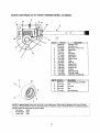
SEARS CRAFTSMAN
5.0 H.P. SNOW THROWER
MODEL 247.886640
9
12
13
5
10
/
6
•
©
15
Key No.
1
2
3
4
5
6
7
8
9
10
11
12
13
14
15
16
17
11
5
Part No.
618-0123
618-0124
710-0642
711-0908
714-0161
715-0143
717-0526
717-0528
718-0186
721-0325
721-0327
736-0351
736-0369
736-0445
737-0168
741-0662
741-0663
618-0120A
Key No. Pa_ No.
1.
634-0114
2.
734-1732
®
/
5
Description
Housing--R.H.
Housing--L.H,
,Hex Screw 1/4-20 x .75
Spiral Axle
Key
Pin-Spiral
_haft-Worm
Gear-Worm
Collar-Thrust
Plug
Seal-Oil
Washer-Flat
Washer-Flat
Washer-Flat
Grease
Bearing-Ftenge
Bearing-Flange
Assembly, Complete 24"
Description
Wheel Assembly, Complete
Tire
3.
734-0255
Air Valve
4.
5.
734-1713
741-0401
Rim
Sleeve Bearing
NOTE: For painted parts, please refer to the list of color codes below. Please add the applicable color code, wherever
needed, to the part number to order a reptacement part. For instance, if s part, numbered 700-xxxx, is painted polo green, |
the part number to order would be 700-xxxx-0689.
Polo Green:
0689
[
Powder Black: 0637
/
Oyster Gray:
0662
|
I
i ...................................................
22
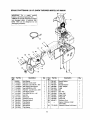
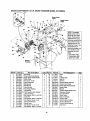
SEARS CRAFTSMAN
5.0 H.P. SNOW THROWER
MODEL 247.886640
IMPORTANT:
For a proper working
machine, use Factory Approved Parts.
V-BELTS are specially designed to engage
and disengage safely. A substitute (non
OEM) V-Belt can be dangerous by not
disengaging completely.
\
2_
27
14 26
22
15
24
24
\
\
2%
Key
No.
1.
2.
3.
4.
5.
6.
7,
8.
9_
10.
11,
12.
13,
14.
15.
16
PaN No.
Description
Key
aty,
Part No.
Description
NO.
05896A
710-0230
i710-0627
710-0654A
710-0696
710-1245
710-1652
710-3005
712-0181
731-1324
732-0339
736-0242
736-0247
736-0270
736-0331
736-0505
Idler Bracket
Hex Bolt 1/4-28 x 0.50"
Hex Bolt: Lock 5/16-24 x .750"
Self-Tapping Sems Screw
Hex Bolt 3/8-24 x ,875"
Hex Bolt : Lock 5/16-24 x .875"
Self-Tapping Screw
Hex Screw 3/8-16 x 1.25"
Jam Nut
Belt Cover
Extension Spring
Beleville Washer
Flat Washer
Bell Washer
Bell Washer
Flat Washer
1
1
2
4
1
1
2
1
1
1
1
1
1
1
1
1
23
17.
18.
19.
20.
21.
22.
23.
24.
25.
26.
27.
28.
29.
736-0507
737-3007
748-0234
748-0360
754-0343
754-0430A
756-0313
756-0569
756-0967
756_0984
756-0985
629-0071
30,
770-10433
Special Washer
Grease
Shoulder Spacer
Pulley: Adapter
V-Belt
Belt
Idler: Flat
Pulley: Half
Auger Pulley
Pulley Half
Pulley Half
Extension Cord
Engine, Craftsman model
143.015007
Operator's Manual (not shown)
1
1
1
1
1
2
1
1
1
1
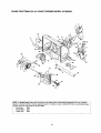
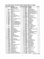
SEARS CRAFTSMAN
5.0 H.P. SNOW THROWER
MODEL 247.886640
1
\
18
14
31
21
%
/
41
39
44
NOTE: For painted parts, please refer to the list of color codes betow.Please add the applicable color code, wherever
needed, to the part number to order a replacement part. For instance, if a part, numbered 700-xxxx, is painted polo green,
the part number to order would be 700-xxxx÷0689.
Polo Green:
0689
Powder Black: 0637
Oyster Gray:
0662
24
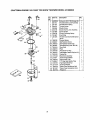
SEARS CRAFTSMAN
I Key No.
1
2
3
4
5
5
7
8
9
10
11
12
13
14
15
17
18
19
20
21
22
23
PaN No,
712-0116
756-0178
784-5632A
710-0459A
738-0281
736-0167
732-0611
712-3068
712-30t0
736-0119
05931
741-0309
710-0451
705-5226
684-0039C
736-0119
736-0242
741-0475
784-5647
731-1379B
712-0324
736-0463
5.0 H.P. SNOW THROWER
Description
Lock Jam Nut 3/8-24
Flat Idler
Auger Idler Arm
Hex Cap Screw 3/8-24 x 1.50
Shoulder Screw
Flat Washer
Extension Spring
Hex Nut 5/16-t8
Hex Nut 5/16-18
Lock Washer 5/16
Bearing Housing
Ball Bearing
Carriage Bolt 5/16-18
Reinforcement Chute
Housing Assembly
Lock Washer 5/16
Bell Washer
Bushing
Chute Crank Bracket
Chute Adapter
Hex Lock Nut 1/4-20
IFlat Washer
Qty.
1
1
1
1
1
1
1
1
13
9
I
1
4
1
1
13
10
1
1
5
5
5
MODEL 247.886640
Key No.
24
25
26
27
28
29
30
31
33
34
35
36
37*
38
39
40
41
42
43
44
45
46
• See page 22 for breakdown ol this assembly.
25
Part No.
710-0451
710-0703
710-0604
736-0169
712-0798
710-0451
784-5580
736-0242
784-5581A
710-0260
684-0065
7t5-0114
618-0120A
605-5188A
736-0188
741-0493A
605-5189A
710-0890A
712-0429
741-0245
784-5618
Description
Carriage Bolt
Carriage Screw 1/4-20 x .75
Hex Washer Screw 5/16-18
Lock Washer 3/8
Hex Nut 3/8-16
Carriage Bolt5/16-18 x .75
Skid Shoe
Bell Washer
Shave Plate
Carriage Bolt 5/16-18 x ,62
Impeller Assembly
Roll Pin
Gear Assembly
Spiral RH
Flat Washer
Flange Bushing
Spiral LH
Shear Bolt 5/16-18 x 1.5
Lock Nut 5/16-18
Hex Flange Bearing
Bearing Housing
Grease
Qty.
6
1
1
4
2
4
2
4
1
2
1
2
1
1
4
4
1
2
2
2
1
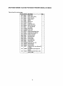
SEARS CRAFTSMAN
5.0 H.P. SNOW THROWER
MODEL 247.886640
5
3
6_
4
9
10
2
<
40
44
\
NOTE: For painted parts, please refer to the list of color codes below. Please add the applicable color code, wherever
needed, to the part number to order a replacement part. For instance, if a part, numbered 700-xxxx, is painted polo green,
the part number to order would be 700-xxxx-0689.
Polo Green:
0689
Powder Black: 0637
Oyster Gray:
0662
26
SEARS CRAFTSMAN
Key No.
1
2
3
4
5
6
7
9
10
11
12
13
14
15
16
17
18
19
2O
21
23
24
25
Part No.
705-5234
705-5233
720-0274
784-5717
735-0199A
749-0910B
749-0911B
731-1500
747-0984
746-0778
712-0121
746-0897
746-0898
712-3010
736-0119
750-1032
726-0135
710-0262
726-0100
720-0201A
705-5204A
736-0242
747-0697
5.0 H.P. SNOW THROWER
Description
Clutch Lever Assembly - RH
Clutch Lever Assembly - LH
Grip
Handle Panel Assembly
Bumper
Handle RH
Handle LH
Pivot Rod Cover
Pivot Rod
I"Z" Fitting
Hex Nut
Auger Clutch Cable
Drive Clutch Cable
Hex Nut 5/16-18
Lock Washer 5/16
Spacer
Push Cap
Carriage Bolt 5/16-18 x 1.5
Push Cap
Chute Crank Knob
Chute Crank Assembly
Bell Washer .340 ID x .873 OD
Eyebolt
Qty.
1
1
2
1
2
1
1
1
1
2
2
1
1
8
8
2
2
4
1
1
1
3
1
MODEL 247.886640
Key No,
26
27
28
31
35
36
37
38
39
40
41
42
43
44
45
46
47
48
49
50
51
52
53
27
PaN No.
735-0234
720-0223
705-5231
710-0599
747-0904
710-3015
,712-3027
732-0733
710-0788
784-5599
710-3180
710-3008
736-0185
714-0104
712-0429
736-0159
731-0921
720-0284
710-0276
T10-0451
731-1300A
712-3027
731-0851A
Description
Rubber Grommet
Grip
Speed Selector Plate
Hex Wash. Screw 1/4-20 x .50
Shift Lever
Hex Cap Screw 1/4-20 x .75
Hex Lock Nut 1/4-20
Shift Lever Support
Hex Washer
Handle Tab
Hex Cap Screw 5/16-18 x 1.75
Hex Cap Screw 5/16-18 x .75
Flat Washer 3/8 ID x .738 OD
Cotter Pin
Hex Lock Nut 5/16-18
Washer 5/16
Qty.
1
1
4
9
8
2
2
2
2
1
3
2
Upper Chute
Wing Knob 5/16-18
Carriage Screw 5/16-18 x 1.0
Carriage Bolt 5/16-18 x .75
Lower Chute
Hex Lock Nut 1/4-20
1
1
1
3
1
6
Chute Flange Keeper
13
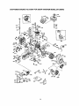
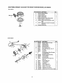
SEARS CRAFTSMAN
5.0 H.P. SNOW THROWER
MODEL 247.886640
27
37
/
39
Drive Clutch
Cable
13
41
7
5
Auger
CaSle Clutch
11
26
10
NOTE: For painted
parts, please refer to
the list of color codes
below. Please add the
applicable color code,
wherever needed, tothe
)art number to order a
replacement part. For
instance, if a part, numbered 700-xxxx, is
painted polo green, the
)art number to order
would be 700-xxxx0689.
Polo Green: 0689
Powder Black: 0637
Oyster Gray: 0662
Housing
Part No,
KeyNo.! 710-1652
2
784-5688
3
784-5687A
4
756-0625
5
736-0924
6
684-0030
7
741-0563
8
736-0105
9
712-0116
lO
741-0598
11
736-0188
12
784-5689A
13
716-0538
14
736-0242
15
714-0474
16
736-0160
17
710-0788
18
784-5590
19
784-5638
2o
710-0699
21
735-0351
Part Description
Hex Screw
Drive Cable Guide Bracket
Auger Clutch Cable Bracket
Roller Cable
Hex Screw 1/4-28
Frame Assembly
Ball Bearing
Bell Washer
Lock Jam Nut
Hex Flange Bearing
Flat Washer
Front Support Guide Bracket
Lock Hex Screw
Bell Washer .340 ID x .872 OD
Cotter Pin
Flat Washer .536 ID x .930 OD
Hex Washer Screw 1/4-20
Frame Shift Bracket
Frame Cover
Hex Washer Screw 1/4-20
Flat Washer .780 ID x .50 OD
Qty.
8
1
1
3
3
1
2
2
1
2
3
1
1
1
1
1
1
1
1
6
1
KeyNo._
22
23
24
25
26
27
28
29
30
31
32
33
34
35
36
37
38
39
40
41
28
PartNo.
717-1445
714-0126
717-1444
715-0249
714-0!43
684-0042C
656-0012A
684-0013B
746-0697
748-0190
684-0021
732-0264
712-0711
746-0898
738-O669
784-5617A
735-0243
718-0301A
618-0063
712-0703
Part Description
Gear
Key
7-Tooth Shaft
Roll Pin
Klik Pin
FrictionWheel Assembly
Friction Disc Wheel
Wheel Shift Rod Assembly
Auger Cable
Spacer
FrictionWheel Bracket Assy.
Extension Spring
Jam Nut 3/8-24
Drive Cable
Axle 13" Wheels
Friction Plate
FrictionWheel Rubber
FrictionWheel Hub
FrictionWheel Bearing
Nut Insert
Qty.
1
1
1
2
2
1
1
1
1
1
1
1
1
1
1
1
1
1
1
4
CRAFTSMAN
ENGINE 143.015007
FOR SNOW THROWER
Key
Part No.
No.
0 i640084A
1
631615
2
_31767
6
640070
7
650506
10 632108
14 631890
15 630735
16 631807
17 651025
18
20
20A
25
27
28
29
30
31
32
33
36
37
40
44
47
48
60
I
I
31.1_
- 25
29
630766
640027
640053
631951
631024
632019
631028
631021
831022
27136A
27554
632745
132547
640183
27110A
630748
631027
632760
MODEL 247.886640
Description
Carburetor (Incl. 184 on page 33)
Throttle Shaft & Lever Assembly
Throttle Return Spring
Throttle Shutter
Shutter Screw
Choke Shaft & Lever Assembly
Choke Shutter
Choke PositioningSpring
Fuel Fitting
Throttle Crack Screw/Idle Speed
Screw
Tension Spring
Idle Restrictor Screw
Idle Restrictor Screw Cap
Float Bowl Ass'y (Incl. 32 & 33)
Float Shaft
Float
Float Bowl "O" Ring
Inlet Needle, Seat & Clip (Incl. 31 )
SpringClip
Bowl Drain Assembly
Drain Plunger Gasket
Main Nozzle Tube
"O" Ring, Main Nozzle Tube
High Speed Bowl Nut
Bowl Nut Washer
Welch Plug, Idle Mixture Well
Welch Plug, Atmospheric Vent
Repair kit
Qty,
1
1
1
1
2
1
1
1
1
1
1
1
1
1
1
1
1
1
1
1
1
1
2
1
1
1
1
1
CRAFTSMAN
ENGINE 143.015007
FOR SNOW THROWER
MODEL 247.886640
76
g_'150
60
262
/
2
287 390
3O
3/70K
CRAFTSMAN
Key No.
0
O
1
2
4
5
14
15
16
,17
18
19
20
25
26
30
40
40
40
41
41
41
Part No.
36469A
26727
0
30969
28277
31334
3,1510
31335
651018
31426
32600
36552
650802
35975
36073
36074
36075
36070
36071
36072
42
36076
42
36077
42
36078
43
20381
45
32875A
46
32610A
48
27241
49
32654
50
_36650
60
29745
64
30063
64A
8345
65
650128
69
27677A
70
34678A
75
27897
76
30318
80
30574A
81
30590A
82
3059,1
83
30588A
86
650488
89
6.10961
90
6.11199
92
650815
93
650816
160
34443B
101
610118
102
651024
103
$51007
ENGINE 143.015007
FOR SNOW THROWER
Description
RPM High 3450 to 3750
RPM Low 1850 to 2150
Cylinder (Incl. 2,20,72 & 125)
Dowel Pin
Oil Drain Exth. (Purchase Local)
Extension Cap
Washer
Governor Rod
Governor Lever
Governor Lever Clamp
Screw, Torx T- 15, 8-32 x 19/64"
Extension Spring
Oil Seal
Blower Housing Baffle (Incl. 262)
Screw, 1/4-20 x 5/8"
Crankshaft
Piston, Pin & Ring Set (Std.)
Piston, Pin & Ring Set (.010" OS)
Piston, Pin & Ring Set (.020" OS)
Piston & Pin Ass'y. (Std.) (Incl. 43)
Piston & Pin Ass'y. (.010" OS)
(Incl. 43)
Piston & Pin Ass'y. (.020" OS)
(Incl. 43)
Ring Set (Std.)
Ring Set (.010" OS)
Ring Set (.020" OS)
Piston Pin Retaining Ring
Connect. Rod Ass'y. (Incl. 46, 49)
Connecting Rod Bolt
Valve Lifter
Oil Dipper
Camshaft (BCR)
Btower Housing Extension
Screw, Torx T-30, 1/4-20 x 1/2"
Washer
Screw, 10-24 x 1/2"
Cylinder Cover Gasket
Cytinder Cover (Incl. 75 thin 83)
Oil Seal
Camshaft Seal
3overnor Shaft
Washer
Governor Gear Ass'y. (Incl. 81)
._overnorSpool
Screw, .1/4-20 x ,1-1/4"
Flywheel Key
Flywheel (WIRing Gear)
Belleville Washer
Flywheel Nut
Solid State Ignition
Spark Plug Cover
Solid State Mounting Stud
Screw, Torx T-15, 10-24 x 15/16"
Qty.
O
0
1
2
1
1
1
1
1
1
1
1
1
1
2
1
1
1
1
1
1
1
1
1
1
2
1
2
2
1
1
1
1
1
1
1
1
1
1
1
1
1
1
7
1
1
,1
1
1
1
2
2
Key No.
110
110A
119
120
125
125
126
126
127
130
130A
130B
135
150
151
169
170
171
172
173
174
176
181
182
183
!84
185
186
200
203
204
206
209
209A
215
219
220
222
223
224
260
262
267
268
274
275
277
285
287
290
292
298
300
301
Part No.
35182
36874
36443
36441
36471
36472
32644A
32645A
650691
602,1A
650694A
650818
35395
31672
3,1673
27234A
27666
11410
14146
35350
650783
29752
650870
6201
34583A
26756
33691
32698
36677
31342
651029
610973
650139
30322
35440
34582
35438
28820
B50664
33673A
35656A
650737
34212
30200
33670A
35771
650327
36467A
650926
30705
26460
650665
35584
35355
MODEL 247.886640
Description
Ground Wire
Ground Wire
Qty.
1
1
1
Cylinder Head Gasket
1
Cylinder Head (Incl. 131)
1
Exhaust Valve (Std.) (Incl. 151)
1
Exhaust Val. (1/32" OS) (Incl. 151
1
Intake Valve (Std.) (Incl. 151)
1
Intake Valve (1/32" OS) (Incl. 151)
Washer
1
Screw, 5/16-18 x 1-1/2"
2
Screw, 5/16-18 x 2"
5
Screw, 5/16-18 x 1-1/2"
1
1
Resistor Spark Plug (RJ 19LM)
2
Valve Spring
2
Valve Spring Cap
Valve Cover Gasket
2
1
Breather Body
Breather Element
1
Valve Cover
1
Breather Tube
1
Screw, 10-24 x 3/4"
2
2
Nut & Lock Washer, 1/4-28"
Screw, 1/4-28 x 1-11/16"
,1
1
Screw, 1/4-26 x 7/8"
Choke Bracket
1
1
Carburetor To Intake Pipe Gasket
1
Intake Pipe
1
Governor Link
1
Control Bracket (Incl. 203-209A)
1
Compression Spring
1
Screw, Torx T-15, 5-40 x 7/16"
terminal
1
2
Screw, 8-32 x 3/4"
2
Lock Nut, 8-32
Control Knob
1
1
Choke Rod
Choke Knob
t
2
Screw, 10-32 x 1/2"
2
Screw, 1/4-20 x 1-19/32"
1
Intake Pipe Gasket
1
Btower Housing
Screw, 1/4-20 x 1/2"
2
Hold Down Bracket
1
1
Screw, !0-24 x 9/16"
Exhaust Gasket
1
1
Muffler (Ind. 274)
Screw, 1/4-20 x 2-27/64"
2
1
Starter Cup
Screw, 8-32 x 21/64"
2
1
Fuel Line
4
Fuel Line Clamp
2
Screw, 1/4-15 x 3/4"
1
Fuel Tank (Incl. 292 & 301)
1
Fuel Cap
Table continued on next page
31
CRAFTSMAN
ENGINE 143.015007
FOR SNOW THROWER
MODEL 247.886640
Table continued from previous page:
Key No.
3O5
3O7
308
310
313
328
329
335
338
340
345
35O
351
355
364
365
370A
370B
370C
370D
370G
370K
38O
390
396
4OO
PaN No.
35554
35499
35539
35556
34080
35062
610973
35072
650257
36247
33344
570682A
32180C
590574
33333
650735
36261
35282
36501
35878
36534
36695
640084A
590742
33290E
36444
420
730226
9OO
754303
Description
lOll FillTube
Qty.
1
1
Oil FillTube "0" Ring
1
Oil FillTube Clip
Dipstick Ass'y,
1
1
iSpacer
2
Ignition Key
Terminal
1
Carburetor Cover
1
2
Screw, 8-32 x 5/16"
Fuel Tank Bracket
!
Heat Baffle
1
1
Primer Ass'y.
Primer Line
1
1
Starter Handle (Mitten Grip)
Carburetor Cover Bracket
1
1
Screw, 10-24 x 3/8"
Lubrication Decal
1
InstructionDecal
1
Primer Decal
1
1
Warning Decal
Instruction Decal
1
Starter Decal
1
1
Carburetor (Incl. 184)
Rewind Starter
1
Electric Starter
1
Gasket Set (Incl. Items Marked PK
1
in Notes)
SAE 5W30 4-Cycle Engine Oil
1
(Quart)
Replacement Short Block, Order
1
From 71-999
32
CRAFTSMAN
ENGINE 143.015007
FOR SNOW THROWER
MODEL 247.886640
Recoil Starter
Pad No.
590742
590740
590616
590617
590645A
590647
590535;
m k-,
13
__,
Description
Rewind Starter
Retainer
Qty.
1
1
Starter Dog
Dog Spring
Pulley & Rewind Spring Ass'y
Starter Housing Ass'y
Starter Rope (Length 98" x 9/64"
dia.)
590574 Mitten Grip Handle (Not included
w/starter)
590760' Spring Clip
2
2
1
t
1
1
1
14
Electric Starter
Key No.
0
2
3
4
5A
6
7
8
9
25
24
16
18
15
33
PeN No.
33290E
,31749
33522
133769
37332
35461
35450
35912
0
10A
13
14
15
35452A
590500
33441
35453
16
19
24
25
26
26
29
30
35454
35911
35462
35456
650819
651032
32450B
650759
Description
Electric Starter (110 Volt)
Retainer Ring
Spring Retainer
Anti-driftSpring
Nut & Gear (Incl. 2)
Drive End Cap Ass'y. (Incl. 7)
"O" Ring
Armature
Housing Ass'y, (Must Purchase
Complete Motor)
Brush & Spring Card Ass'y,
Thrust Washer
Ground Screw
Commutator End Cap Ass'y,
(Incl. 7)
Switch Box Ass'y.
Thrust Washer
Case Bolt
Grounding Screw
Screw, 6-32 x 2-1/2"
Screw, 12-16 x 5/8"
Extension Cord (10'6")
Screw, Torx T-30, 1/4-20 x 23/32
_y.
1
1
1
1
1
1
2
1
1
1
1
1
1
t
0
2
1
2
2
1
3