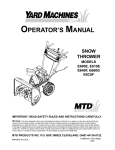
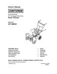
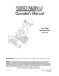
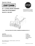
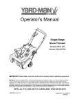
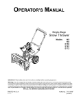
1
Operator's Manual
Single-Stage
Snow Thrower
Models
230,$230
240,$240
250, S250
260,$260
IMPORTANT: Read safety rules and instructions carefully before operating equipment.
Warning:
This unit is equipped with an internal combustion engine and should not be used on or near any unimproved forest-covered, brushcovered or grass-covered land unless the engine's exhaust system is equipped with a spark attester meeting applicable local or state laws (if
any). If a spark arrester is used, it should be maintained in effective working order by the operator. In the State of California the above is required
by law (Section 4442 of the California Public Resources Code). Other states may have similar laws. Federal laws apply on federal lands. A spark
arrester for the muffler is available through your nearest engine authorized service dealer or contact the service department, P.O. Box 361131
Cleveland, Ohio 44136-0019.
MTD LLC, P.O. BOX361131CLEVELAND,OHIO44136-0019
PRINTED IN U.S.A.
FORM NO. 769-01283.
(5/24/2004)
TABLEOFCONTENTS
Content
Customer
Support
Important
SafeOperationPractices
Assembly
Controls
Operation
Page
2
Content
Maintenance
Page
8
3
5
6
Service & Adjustments
Accessories & Kits
Illustrated Parts List
7
Warranty
8
11
12
Back Cover
FINDINGMODELNUMBER
This Operator's Manual is an important part of your new snow thrower. It will help you assemble, prepare and
maintain the unit for best performance. Please read and understand what it says.
/
Before you start assembling your new equipment, please locate the model plate on the equipment
and copy the information from it in the space provided below. A sample model plate is also given below.
You can locate the model plate by standing behind the unit and looking at the rear of the snow thrower
frame. This information will be necessary to use the manufacturer's web site and/or help from the
Customer Support Department or an authorized service dealer.
P. O. BOX
,
351131
_TD LLC
CLEVELAND,OF_
cts corn
330-22Q-4683
800-8Q0-7310
44136
I
mo .nm e
Copy the serial number here:
CUSTOMER
SUPPORT
Please do NOTretum the unit tothe retailer from where it waspurchased,withoutfirst contactingCustomerSupport.
If you have difficulty assembling this product or have any questions regarding the controls, operation or
maintenance of this unit, you can seek help from the experts. Choose from the options below:
you will
Visit
mtdproducts.com
get the four options
for reproduced
many useful here.
suggestions.
Click on the
Clickappropriate
on Customer
button
Support
and help
button
is and
immediately available.
7?_e answe_ _ you
a mouse c#ck aw_y,f
If you prefer to reach a Customer Support Representative, please call 1(800) 800-7310.
\En
ine
The engine manufacturer is responsible for all engine-related issues with regards to
3erformance, power-rating, specifications, warranty and service. Please refer to the engine
manufacturer's Owner's/Operator's Manual, packed separately with your unit, for more
information.
ale
SECTION1: IMPORTANT
SAFEOPERATION
PRACTICES
WARNING:
This symbol points out important safety instructions which, if not followed, could endanger the
personal safety and/or property of yourself and others. Read and follow all instructions in this manual before
attempting to operate this machine. Failure to comply with these instructions may result in personal injury. When you
see this symbol--heed
its warning.
WARNING:
Engine Exhaust, some of its constituents, and certain vehicle components
known to State of California to cause cancer and birth defects or other reproductive harm.
contain or emit chemicals
DANGER:
This machine was built to be operated according to the rules for safe operation in this manual. As with
any type of power equipment, carelessness or error on the part of the operator can result in serious injury. This
machine is capable of amputating hands and feet and throwing objects. Failure to observe the following safety
instructions could result in serious injury or death.
Training
1.
2.
3.
4.
5.
6.
7.
Read, understand, and follow all instructions on the
machine and in the manual(s) before attempting to
assemble and operate. Keep this manual in a safe place
for future and regular reference and for ordering
replacement parts.
Be familiar with all controls and their proper operation.
Know how to stop the machine and disengage them
quickly.
Never allow children under 14 years old to operate this
machine. Children 14 years old and over should read and
understand the operation instructions and safety rules in
this manual and should be trained and supervised by a
parent.
Never allow adults to operate this machine without proper
instruction.
Thrown objects can cause serious personal injury. Plan
your snow throwing pattern to avoid discharge of material
toward roads, bystanders and the like.
Keep bystanders, helpers, pets and children at least 75
feet from the machine while it is in operation. Stop
machine if anyone enters the area.
Exercise caution to avoid slipping or falling, especially
when operating in reverse.
8.
9.
Preparation
1.
2.
3.
4.
5.
6.
7.
Thoroughly inspect the area where the equipment is to be
used. Remove all door mats, newspapers, sleds, boards,
wires and other foreign objects which could be tripped
over or thrown by the auger/impeller.
Always wear safety glasses or eye shields during
operation and while performing an adjustment or repair to
protect your eyes. Thrown objects which ricochet can
cause serious injury to the eyes.
Do not operate without wearing adequate winter outer
garments. Do not wear jewelry, long scarves or other
loose clothing which could become entangled in moving
parts. Wear footwear which will improve footing on
slippery surfaces.
Use a grounded three wire extension cord and receptacle
for all units with electric start engines.
Adjust collector housing height to clear gravel or crushed
rock surfaces.
Disengage the control handle before starting the engine.
Never attempt to make any adjustments while engine is
running, except where specifically recommended in the
operator's manual.
Let engine and machine adjust to outdoor temperature
before starting to clear snow.
To avoid personal injury or property damage use extreme
care in handling gasoline. Gasoline is extremely
flammable and the vapors are explosive. Serious
personal injury can occur when gasoline is spilled on
yourself or your clothes which can ignite. Wash your skin
and change clothes immediately.
a. Use only an approved gasoline container.
b. Extinguish all cigarettes, cigars, pipes and other
sources of ignition.
c. Never fuel machine indoors.
d. Never remove gas cap or add fuel while the
engine is hot or running.
e. Allow engine to cool at least two minutes before
refueling.
f.
Never over fill fuel tank. Fill tank to no more than V2
inch below bottom of filler neck to provide space
for fuel expansion.
g. Replace gasoline cap and tighten securely.
h. If gasoline is spilled, wipe it off the engine and
equipment. Move machine to another area. Wait 5
minutes before starting the engine.
i.
Never store the machine or fuel container inside
where there is an open flame, spark or pilot light
(e.g. furnace, water heater, space heater, clothes
dryer etc.).
j.
Allow machine to cool at least 5 minutes before
storing.
Operation
1.
2.
3.
4.
5.
Do not put hands or feet near rotating parts, in the auger
housing or discharge chute. Contact with the rotating
parts can amputate hands and feet.
The auger control handle is a safety device. Never
bypass its operation. Doing so, makes the machine
unsafe and may cause personal injury.
The control handle must operate easily in both directions
and automatically return to the disengaged position when
released.
Never operate with a missing or damaged discharge
chute. Keep all safety devices in place and working.
Never run an engine indoors or in a poorly ventilated
area. Engine exhaust contains carbon monoxide, an
odorless and deadly gas.
6. Donotoperate
machine
whileundertheinfluence
of
MaintenanceAndStorage
alcohol
ordrugs.
tamper with safety devices. Check their proper
7. Muffler
andengine
become
hotandcancause
aburn.Do 1. Never
operation
regularly.
nottouch.
2. Disengage the control handle and stop engine. Wait until
8. Exercise
extreme
caution
whenoperating
onorcrossing
the auger/impeller come to a complete stop. Disconnect
gravel
surfaces.
Stayalertforhidden
hazards
ortraffic.
the spark plug wire and ground against the engine to
9. Exercise
caution
whenchanging
direction
andwhile
prevent unintended starting before cleaning, repairing, or
operating
onslopes.
inspecting.
10.Planyoursnow
throwing
pattern
toavoiddischarge
3. Check bolts, and screws for proper tightness at frequent
towards
windows,
walls,carsetc.Toavoidproperty
intervals to keep the machine in safe working condition.
damage
orpersonal
injurycaused
bya ricochet.
Also, visually inspect machine for any damage.
11.Never
directdischarge
atchildren,
bystanders
andpets
4. Do not change the engine governor setting or over-speed
orallowanyone
infrontofthemachine.
the engine. The governor controls the maximum safe
12.Donotoverload
machine
capacity
byattempting
toclear
operating speed of the engine.
snowattoofastofa rate.
5. Snow thrower shave plates and skid shoes are subject to
13.Never
operate
thismachine
without
goodvisibility
orlight.
wear and damage. For your safety protection, frequently
Always
besureofyourfooting
andkeepafirmholdon
check all components and replace with original
thehandles.
Walk,neverrun.
equipment manufacturer's (O.E.M.) parts only. "Use of
14.Disengage
power
totheauger/impeller
when
parts which do not meet the original equipment
transporting
ornotinuse.
specifications may lead to improper performance and
15.Never
operate
machine
athightransport
speeds
on
compromise safety!"
slippery
surfaces.
Lookdownandbehind
andusecare
6. Check controls periodically to verify they engage and
wheninreverse.
disengage properly and adjust, if necessary. Refer to the
16.Ifthemachine
should
starttovibrate
abnormally,
stopthe
adjustment section in this operator's manual for
engine,
disconnect
thesparkplugandground
itagainst
instructions.
theengine.
Inspect
thoroughly
fordamage.
Repair
any
7. Maintain or replace safety and instruction labels, as
damage
before
starting
andoperating.
17.Disengage
thecontrol
handle
andstopengine
before
you 8. necessary.
Observe proper disposal laws and regulations for gas, oil,
leavetheoperating
position
(behind
thehandles).
Wait
etc. to protect the environment.
untiltheaugercomes
toacomplete
stopbefore
9. Prior to storing, run machine a few minutes to clear snow
unclogging
thedischarge
chute,making
any
from machine and prevent freeze up of auger/impeller.
adjustments,
orinspections.
10. Never store the machine or fuel container inside where
18.Never
putyourhandinthedischarge
orcollector
there is an open flame, spark or pilot light such as a water
openings.
Always
useaclearing
tooltounclog
the
heater, furnace, clothes dryer etc.
discharge
opening.
11. Always refer to the operator's manual for proper
19.Useonlyattachments
andaccessories
approved
bythe
instructions on off-season storage.
manufacturer.
20. Ifsituations
occurwhicharenotcovered
inthismanual, YourResponsibility:
usecareandgoodjudgment.
Contact
yourdealer
or
•
Restrict the use of this power machine to persons who
telephone
1-800-800-7310
forassistance
andthename
read, understand and follow the warnings and
ofyournearest
servicing
dealer.
instructions in this manual and on the machine.
SECTION2: ASSEMBLING
YOURSNOWTHROWER
NOTE: This Operator's Manual covers several models.
Snow thrower
features
vary by model. Not all
features discussed in this manual are applicable to all
snow thrower models.
ContentsofCarton
Carton contents are listed below with part numbers in
parentheses.
•
•
•
Two Ignition Keys (725-0201)
Bottle of 2 cycle oil
Extension Cord (if so equipped)
NOTE: All references to left or right side of the snow
thrower is from the operating position only.
,_
WARNING:
sparktoplug
wire
and ground it Disconnect
against the the
engine
prevent
unintended starting.
Positioningthe UpperHandle
•
•
•
Remove packing material, if present.
Making sure not to pinch the cable in the process,
pivot the upper handle into the operating position as
illustrated until it clicks into place.
Tighten the wing knobs to secure the handle in
place.
Assembling
theDischargeChute
For shipping reasons, the snow thrower has been
packaged with the upper chute pivoted all the way
down. To pivot it upward, proceed as follows:
•
•
•
•
Turn the chute until the chute opening is facing
straight ahead.
Remove the wing knob, flat washer and carriage
bolt from the lower chute.
Pivot the upper chute upward over the lip on the
lower chute so that there is NO gap between the
upper chute and the lower chute.
Resecure with the hardware just removed.
IMPORTANT:Do not use the chute handle to lift the snow
thrower.
_/iiii
i!!/_
SECTION3: KNOWYOURSNOWTHROWER
Chute Handle
Starter Handle*
Discharge Chute
Primer
Spark Plug Cover
\
\
Fuel Cap
Choke
Ignition Key
Upper Handle
Shave Plate
Electric Starter Plug
(If So Equipped)
Electric Starter Button
(If So Equipped)
Auger Control Handle
Auger
* Styles vary by model
Figure 1
IMPORTANT:This unit runs on a mixture of gasoline
and oil. Do NOT operate the snow thrower without first
reading the Tecumseh engines operator's manual for
instructions regarding proper fuel and engine oil.
Electric Starter Plug (If so equipped)
Requires use of a two-prong outdoor extension cord
(packed with the snow thrower) and a 120V power
source/wall outlet.
Choke Lever
Spark Plug Cover
OFF
1111
CHOKE
Illl
Remove the spark plug cover to access the engine's
spark plug located beneath it.
ON
Activating the choke control closes the choke plate on
the carburetor and aids in starting the engine. Refer to
the engine manual packed with the snow thrower for
more detailed instructions regarding the choke.
Primer
Depressing the primer forces fuel
directly into the engine's carburetor to
aid in cold-weather starting. Refer to
the engine manual packed with the
snow thrower for more detailed
instructions regarding the primer.
_ PRIMER
O
PUSH
FOR
A
. COLO_.Q,._
IgnitionKey
The ignition key must be present,
inserted in the key switch, and in the
"ON" position for the engine to start.
_ ff-_"_,_,_
,GNmON
Starter Handle
Auger
When engaged, the augers rotation draws snow into
the auger housing and throws it out the discharge
chute. The rubber paddles on the augers also aid in
propelling the snow thrower as they come in contact
with the pavement.
Auger ControlHandle
Located on the upper handle, the auger control handle
is used to engage and disengage drive to the auger.
Squeeme the control handle against the upper handle to
engage the auger; release it to disengage.
DischargeChute / Chute Handle
Rotate the discharge chute to the left or right using the
chute handle. The pitch of the discharge chute controls
the angle at which the snow is thrown. Loosen the wing
knob on the side of the discharge chute before pivoting
the discharge chute upward or downward. Retighten
the knob once the desired position has been achieved.
The starter handle is used to manually start the engine.
Shave Plate
Electric Starter Button (If so equipped)
The shave plate maintains contact with the pavement
as the snow thrower is propelled, allowing the snow
close to the pavement's surface to be discharged.
Pressing the electric starter button engages the
engine's electric starter when plugged into a 120V
power source
SECTION4: OPERATING
YOURSNOWTHROWER
read,
understand,Before
and follow
instructions
WARNING:
startingall the
engine,
and warnings on the machine and in this
manual before operating.
Wing Knob
Fuel AndOil Mixture
Chute Handle
\
Upper Chute
handling gasoline.
extremely
WARNING:
Use Gasoline
extreme iscare
when
flammable and the vapors are explosive.
Never fuel machine indoors or while the
engine is hot or running. Extinguish cigarettes,
cigars, pipes and other sources of ignition.
Your snow thrower is equipped with a two-cycle
engine that requires a mixture of gasoline and two
cycle engine oil at a ratio of 50:1. Refer to the
Tecumseh engines operator's manual for detailed
instructions regarding oil and gasoline for your snow
thrower's engine.
Figure 2
IMPORTANT: Do NOT operate the snow thrower without
the fuel cap securely in place on the fuel tank.
Positioning the DischargeChute
•
Loosen the wing knob found on the left side of the
discharge chute and pivot the upper chute upward
or downward to the desired pitch. Retighten the
wing knob before operating the snow thrower.
•
Rotate the discharge chute to the left or right using
the chute handle. See Figure 2.
Startingthe Engine
•
Auger Control Handle
Refer to the Engines manual packed with the snow
thrower for detailed instructions regarding starting
the engine.
Clearing Snow
NOTE: For more efficient snow clearing,
snow down wind whenever possible.
discharge
Figure 3
,_'_
•
•
WARNING:
the the
snow thrower
with bystanders Never
in frontoperate
of or near
discharge chute opening.
Engage the auger by squeezing the control handle
against the upper handle. See Figure 2.
Lift up slightly on the handle to allow the rubber
paddles on the auger to contact the pavement and
propel the snow thrower forward.
IMPORTANT: Excessive upward pressure on the handle
will result in premature wear on the rubber auger
paddles or possible damage or marking of pavement.
Resulting wear would not be covered by warranty.
•
As the snow thrower starts to move, maintain a firm
hold on the handle, and guide the snow thrower
along the path to be cleared.
•
Release the auger control handle to stop the snow
throwing action and the forward motion.
Stopping the Engine
,_
areas become Muffler,
WARNING:
hot and engine
can cause
and surrounding
a burn. Do
not touch.
After clearing snow, allow the engine to run for an
extra few minutes before storing to help dry any
moisture on the engine.
To stop the engine: Turn the ignition key
counterclockwise to the OFF position. Refer to
Ignition Key on page 6. Remove the key form the
snow thrower's ignition switch before storing.
SECTION5: MAKINGADJUSTMENTS
,_
Move the shave plate to desired position and
retighten the nuts and bolts. Make certain all four
nuts are securely tightened.
adjustments
the engine
is running.
WARNING: whileNEVER
attempt
to make any
ShavePlate
•
To check the adjustment of the shave plate, place
the unit on a level surface. The wheels, shave plate
and augers should all contact the level surface.
Note that if the shave plate is adjusted too high,
snow may blow under the housing. If the shave
plate wears out excessively, or the unit will not selfpropel, the shave plate may be adjusted too low.
NOTE: On new units or units with a new shave plate
installed, the augers may be slightly off the ground.
•
To adjust, tip the snow thrower back so that it rests
on the handle. Loosen the lock nuts from the
carriage bolts which secure the shave plate to the
housing. See Figure 4.
Carriage Bolts
Shave Plate
Figure 4
SECTION6: MAINTAININGYOURSNOWTHROWER
WARNING:
Before servicing, repairing, or
inspecting, disengage the control handle and
stop engine. Wait until all moving parts have
come to a complete stop. Disconnect spark
plug wire and ground it against the engine to
prevent unintended starting.
•
•
Gently grasp the idler bracket and pivot it upward to
ease tension on the drive belt. See Figure 5.
While holding the idler bracket up, carefully slip the
drive belt off the engine pulley. See Figure 5.
IRe
Pulley
Lubrication
•
Lubricate pivot points on the control handle and the
extension spring at the end of the clutch cable with
a light oil once every season and before storage of
the snow thrower at the end of the season.
(
©
C
Hardware
Check the engine and snow thrower frequently for
loose or missing hardware, and tighten or replace as
necessary.
Replacingthe DriveBelt
The snow thrower's drive belt is subject to wear and
should be replaced if any signs of cracking, shredding
or rotting is present. To change the drive belt, proceed
as follows:
•
Remove the belt cover from the left side of the
snow thrower's auger housing by unthreading the
five hex screws which secure it in place.
Drive Belt
Auger Pulley
Figure 5
Carefully release the idler bracket and allow it to
pivot downward.
Carefully slip the drive belt off the auger pulley,
freeing it from the snow thrower. See Figure 5.
•
•
Installthereplacement
drivebeltbyfollowingthe
preceding
stepsin reverseorder.
Reattach
thebeltcoverwiththefivehexscrews
removedearlier.
•
•
Adjust the shave plate as instructed in the Making
Adjustments
section on page 8 of this manual.
Tighten the nuts securely before operating the
snow th rower.
Replacingthe ShavePlate
Replacingthe Auger'sRubber Paddles
The shave plate is subject to wear and should be
checked periodically. There are two wearing edges and
the shave plate can be reversed after one side wears
out.
The snow thrower auger's rubber paddles are subject
to wear and should be replaced ifany signs of
excessive wear is present.
To replace (or reverse) the shave plate, proceed as
follows:
NOTE: Call 1-800-800-7310 for information regarding
price and availability of Shave Plate Kit 753-0451 or
contact an authorized MTD Service Dealer in your area.
•
•
Remove the four carriage bolts and hex lock nuts
which secure it to the snow thrower's auger
housing. Refer to Figure 4.Figure 4
Install the new shave plate (or reverse the existing
one, if both sides are not yet worn), making sure the
heads of the carriage bolts are on the inside of the
housing. The lock nuts should be on the outside of
the housing.
NOTE: Carl 1-800-800-7310 for information regarding
the price and availability of Auger Kit 753-04472 or
contact an authorized MTD Service Dealer in your
area).
To change the rubber paddles, proceed as follows:
•
•
Remove the existing rubber paddles by
unthreading the self-tapping screws which secure
them to the auger.
Secure the replacement rubber paddles to the
auger using the hardware removed earlier.
Engine
Refer to the Tecumseh engine manual packed with the
snow thrower for detailed instructions regarding all
engine-related maintenance.
SECTION7: OFF-SEASON
STORAGE
,_
•
•
•
tank
indoors or Never
in enclosed,
poorly with
ventilated
WARNING:
store engine
fuel in
areas where fuel fumes may reach an open
flame, spark or pilot light as on a furnace,
water heater, clothes dryer, or other gas
appliance.
Clean snow thrower thoroughly.
Lubricate as instructed in the Maintaining Your
Snow Thrower section on page 8 of this manual.
Refer to the Engines manual packed with the snow
thrower for detailed instructions regarding all
engine-related storage instructions.
•
•
Store the snow thrower in a clean, dry area.
Place blocks under the front of the auger housing
so that the snow thrower is not resting on the
rubber auger paddles. The rubber can become
misshaped if it supports the weight of the snow
thrower for several months of storage.
NOTE: When storing any type of power equipment in a
poorly ventilated or metal storage shed, care should be
taken to rustproof the equipment, especially springs,
cables and all moving parts.
SECTION8: TROUBLESHOOTING
GUIDE
Problem
Engine fails to start
Cause
Remedy
2.
Key not in ignition switch or not in ON position.
Fuel tank empty, or stale fuel
1.
2.
3.
4.
5.
Blocked fuel line
Spark plug wire disconnected
Faulty spark plug
3.
4.
5.
1.
2.
Unit running with choke in ON position
Fuel line blocked, or stale fuel
1.
2.
3.
4.
Water or dirt in fuel system
Carburetor out of adjustment
3.
4.
Move choke lever to OFF position.
Clean fuel line and fill tank with fresh, clean
gasoline/oil.
Refer to engine manual for remedy.
Refer to engine manual.
Loss of power
1.
2.
Spark plug wire loose
Engine exhaust pipe plugged.
1.
2.
Connect and tighten spark plug wire.
Remove obstruction from exhaust pipe.
Excessive vibration
1.
Loose parts or damaged auger
1.
Stop engine immediately and disconnect
spark plug wire. Check for possible
damage. Tighten all bolts and nuts. Repair
as needed. If the problem persists, take unit
to an authorized MTD service dealer.
Unit fails to self-propel
1.
Drive belt damaged
1.
Inspect the drive belt for damage and
replace if necessary as instructed on page
8 of this manual.
Unit fails to discharge
snow
1.
Discharge chute clogged
1.
2.
Foreign object lodged in auger
2.
3.
Drive belt damaged
3.
Stop engine immediately and disconnect
spark plug wire. Clean discharge chute and
the auger housing.
Stop engine immediately and disconnect
spark plug wire. Remove object.
Inspect the drive belt for damage and
replace if necessary as instructed on page
8 of this manual.
Engine runs erratic
1,
10
Insert key and turn to ON position
Fill tank with clean fresh gasoline/oil
mixture as specified in the engine manual.
Clean fuel line
Connect wire to spark plug.
Clean spark plug, readjust gap, or replace.
SECTION9: ACCESSORIES
& KITS
The following accessories and kits are available for single-stage, two-cycle snow throwers. See the retailer from
which you purchased your snow thrower, an authorized MTD Service Dealer or phone (800) 800-7310 for
information regarding price and availability.
MODEL
OEM-390-697
DESCRIPTION
Electric Start Kit
(fits models with a two-cycle
OEM-390-996
Tecumseh 3 HP or 3.5 HP engine)
Electric Start Kit
(fits models with a two-cycle
Tecumseh 4.5 HP - 5.5 HP engine)
OEM-737-0325
MTD two-cycle snow thrower oil (contains six 2.6 oz. bottles)
753-0451
Shave Plate (includes replacement shave plate and hardware)
753-04472
Rubber Auger Kit, Snow Thrower Single Stage
11
SECTION10: PARTSLIST
81
43
74
73
26
78
46
41
7O
32
43
75
40
64
59 _
39
43
"_
(_47
71
13
.d
29
54
6
I
'_6_'_43
63
24
19
12
23
v
12
REE
NO.
1
2
3
4
5
6
7
8
9
10
11
12
13
14
15
16
17
18
19
20
22
23
24
25
26
27
28
29
30
31
32
33
34
35
36
37
38
39
40
41
42
43
PART
NO.
684-04027A
684-04025
710-0896
735-04032
735-04033
684-04028
710-0134
710-1003
710-3008
710-0653
710-0597
710-1005
710-0433
712-04064
736-0176
726-0299
731-1033
732-0357A
736-0176
736-0326
741-0919
741-0600
746-04091
748-0234
749-04114
750-04230
790-00062
784-5174
790-00039
790-00045
710-0487
720-0284
725-0157
736-0451
747-04165
749-1092A
734-04070
684-04043*
684-04044**
710-1882
710-1003
712-0252
712-04063
REF.
NO.
44
45
46
47
48
49
50
51
DESCRIPTION
Auger Assembly Complete, 21"
Auger Weldment Assembly, 21"
Self-tapping Screw, 1/4-14 x 0.625"
Rubber Spiral
Rubber Paddle
Auger Housing Assembly 21"
Carriage Bolt, 1/4-20 x .62"
Screw, #10-16 x .625
Screw, 5/16-18 x .75
Self-tapping Screw, 1/4-20 x .375
Hex Screw, 1/4-20 x 1.00 Gr. 5
Hex Cap Screw, 1/4-14 x .50"
Hex Cap Screw, 1/4-20 x .625"
Hex Flange Lock Nut, 1/4-20
Flat Washer, .265 x .938 x .120
Push Cap, 1/2"
Shave Plate, 2.66 x 19.88
Extension Spring, .33 OD x 1.12
Fiat Washer, .265 x .938 x .120
Flat Washer, .510 x 1.00 x .125
Ball Bearing
Ball Bearing, 17 x 40 x 12
Clutch Cable
Shoulder Spacer
Lower Handle
52
53
54
55
56
57
58
59
60
61
62
63
64
65
Flange Spacer
Belt Keeper
Bearing Cup
Idler Bracket w/Brake
Belt Cover
Carriage Bolt, 5/16-18 x 2.0
Handle Knob Assembly, 5/16-18
Cable Tie
Saddle Washer, .320 ID x .93
Bail
66
Upper Handle
Wheel-3 spoke, 7 x 1.61
Shroud Assembly
Shroud Assembly
Hex Flange Screw 5/16-18 x 1.50 Gr. 5
Hex Cap Screw, #10-16 x .625"
Hex Nut, 5/8-32 x .12
Hex Flange Lock Nut, 5/16-18, Gr. 5
76
67
68
69
70
71
72
73
74
75
77
78
79
8O
81
82
PART
NO.
725-0201
725-2018
731-1133C
7510009636
736-0225
7512B1476
710-0627
710-0805"
710-3025"*
726-0205
736-0242
747-04150
750-0589*
750-0716"
751-0535-17
751-10049
751-10023
754-0367*
754-0101A**
756-0416B
756-0550*
756-0475**
790-00048
7519630
712-3004A
723-0345
7511824110
710-04187
736-0362
736-0400
629-0236
736-0159
710-04071
710-0451
732-04111
720-0284
731-04127
731-04353
731-04886
731-04388
731-04426
736-0119
DESCRIPTION
Key
Key Switch
Plastic Cap, 1.75 Dia x .72
Recoil Handle (Mitten Grip)
Lock Washer Internal, .625 x 1.058
Primer Button
Hex Screw, 5/16-24 x .75 Gr. 75
Hex Screw, 5/16-18 x 1.50 Gr. 5
Hex Screw, 5/16-18 x .625 Gr. 5
Hose Clamp
Cupped Washer, .340 x .872 x .060
Gas Tank Wire Support
Spacer, .325 ID x .625 OD x .88
Spacer
Fuel Line
Fuel Cap
Fuel Tank, 2 Quart
V-Belt, 3/8
V-Belt, 1/2
Pulley Half, .625 ID x 2.25 OD
Pulley, 3/8 x 1/2-20 x 6.0
Pulley, 1/2 x 1/2-20 x 6.0
Mounting Bracket Support
Recoil Handle
Hex Flange Lock Nut 5/16-18 Gr. 5
Primer Tube
Choke Lever Knob
Hex Screw, 1/4-15 x .50
Flat Washer, .320 x 1.25
Flat Washer, .194 x .62 x .063
Extension Cord, 2-Prong
Flat Washer, .349 x .879 x .063
Carriage Screw, 5/16-18 x 1.0
Carriage Bolt, 5/16-18 x.075
Chute Adjustment Spring
Handle Knob Assembly, 5/16-18
Lower Chute 5" Dia
Lower Chute Ring
Chute Adapter, 5" Dia
Chute Handle
Upper Chute w/Export Label
Lock Washer, 5/16
* Model 240 only
** Model 250/S250, 250/S250 & 230/S230
IMPORTANT: For a proper
working machine, use
Factory Approved Parts.
V-belts are designed to
engage and disengage
safely. A substitute (non
OEM) V-belt can be
dangerous by not
disengaging completely.
NOTE:
Snow thrower features/components
vary by model. NOT all parts listed above and pictured on the previous page are standard equipment.
13
NOTES
14
NOTES
15
MANUFACTURER'S
LIMITED WARRANTY
The limited warranty set forth below is given by MTD LLC with
respect to new merchandise purchased and used in the
United States, its possessions and territories.
"MTD'warrants this product against defects in material and
workmanship for a period of two (2) years commencing on the
date of original purchase and will, at its option, repair or
replace, free of charge, any part found to be defective in
materials or workmanship. This limited warranty shall only
apply if this product has been operated and maintained in
accordance with the Operator's Manual furnished with the
product, and has not been subject to misuse, abuse,
commercial use, neglect, accident, improper maintenance,
alteration, vandalism, theft, fire, water, or damage because of
other peril or natural disaster. Damage resulting from the
installation or use of any part, accessory or attachment not
approved by MTD for use with the product(s) covered by this
manual will void your warranty as to any resulting damage.
Normal wear parts are warranted to be free from defects in
material and workmanship for a period of thirty (30) days from
the date of purchase. Normal wear parts include, but are not
limited to items such as: batteries, belts, blades, blade
adapters, grass bags, rider deck wheels, seats, snow thrower
skid shoes, shave plates, auger spiral rubber and tires.
HOW TO OBTAIN SERVICE: Warranty service is available,
WITH PROOF OF PURCHASE, through your local authorized
service dealer. To locate the dealer in your area, check your
Yellow Pages, or contact MTD LLC at P.O. Box 361131,
Cleveland, Ohio 44136-0019, or call 1-800-800-7310 or 1330-220-4683 or log on to our Web site at
www.mtdproducts.com.
This limited warranty does not provide coverage in the
following cases:
a.
b.
c.
d.
The engine or component parts thereof. These items
may carry a separate manufacturer's warranty. Refer
to applicable manufacturer's warranty for terms and
conditions.
Log splitter pumps, valves, and cylinders have a
separate one year warranty.
Routine maintenance items such as lubricants, filters,
blade sharpening, tune-ups, brake adjustments, clutch
adjustments, deck adjustments, and normal
deterioration of the exterior finish due to use or
exposure.
Service completed by someone other than an
authorized service dealer.
e.
f.
g.
FOR:
MTD does not extend any warranty for products sold or
exported outside of the United States, its possessions
and territories, except those sold through MTD's
authorized channels of export distribution.
Replacement parts that are not genuine MTD parts.
Transportation charges and service calls.
No implied warranty, including any implied warranty of
merchantability of fitness for a particular purpose,
applies after the applicable period of express written
warranty above as to the parts as identified. No other
express warranty, whether written or oral, except as
mentioned above, given by any person or entity,
including a dealer or retailer, with respect to any product,
shall bind MTD. During the period of the warranty, the
exclusive remedy is repair or replacement of the product
as set forth above.
The provisions as set forth in this warranty provide the
sole and exclusive remedy arising from the sale. MTD
shall not be liable for incidental or consequential loss or
damage including, without limitation, expenses incurred
for substitute or replacement lawn care services or for
rental expenses to temporarily replace a warranted
product.
Some states do not allow the exclusion or limitation of
incidental or consequential damages, or limitations on how
long an implied warranty lasts, so the above exclusions or
limitations may not apply to you.
In no event shall recovery of any kind be greater than the
amount of the purchase price of the product sold. Alteration
of safety features of the product shall void this warranty.
You assume the risk and liability for loss, damage, or injury to
you and your property and/or to others and their property
arising out of the misuse or inability to use the product.
This limited warranty shall not extend to anyone other than the
original purchaser or to the person for whom it was purchased
as a gift.
HOW STATE LAW RELATES TO THIS WARRANTY: This
limited warranty gives you specific legal rights, and you may
also have other rights which vary from state to state.
IMPORTANT: Owner must present Original
Purchase to obtain warranty coverage.
Proof of
MTD LLC, P.O.BOX361131CLEVELAND,0HI0 44136-0019; Phone: 1-800-800-7310,1-330-220-4683