1
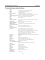
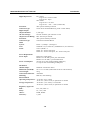
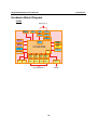
IA261/262 Hardware User’s Manual First Edition, January 2008 www.moxa.com/product MOXA Inc. Tel: +886-2-2910-1230 Fax: +886-2-2910-1231 Web: www.moxa.com MOXA Technical Support [email protected] Worldwide: The Ameraicas: [email protected] IA261/262 Hardware User’s Manual Any software described in this manual is furnished under a license agreement and may be used only in accordance with the terms of that agreement. Copyright Notice Copyright © 2008 MOXA Inc. All rights reserved. Reproduction without permission is prohibited. Trademarks MOXA is a registered trademark of The MOXA Inc. All other trademarks or registered marks in this manual belong to their respective manufacturers. Disclaimer Information in this document is subject to change without notice and does not represent a commitment on the part of MOXA. MOXA provides this document “as is,” without warranty of any kind, either expressed or implied, including, but not limited to, its particular purpose. Moxa reserves the right to make improvements and/or changes to this manual, or to the products and/or the programs described in this manual, at any time. Information provided in this manual is intended to be accurate and reliable. However, MOXA assumes no responsibility for its use, or for any infringements on the rights of third parties that may result from its use. This product might include unintentional technical or typographical errors. Changes are periodically made to the information herein to correct such errors, and these changes are incorporated into new editions of the publication. Table of Contents Chapter 1 Introduction ..................................................................................................1-1 Overview.................................................................................................................................. 1-2 Package Checklist .................................................................................................................... 1-2 Product Features ...................................................................................................................... 1-3 Product Hardware Specifications............................................................................................. 1-4 Hardware Block Diagram ........................................................................................................ 1-6 Chapter 2 Hardware Introduction.................................................................................2-1 Appearance .............................................................................................................................. 2-2 Dimensions (unit = mm) .......................................................................................................... 2-3 LED Indicators......................................................................................................................... 2-4 Reset Button............................................................................................................................. 2-4 Real Time Clock ...................................................................................................................... 2-5 Placement Options ................................................................................................................... 2-5 DIN-Rail Mounting .................................................................................................... 2-5 Wall Mounting (optional)........................................................................................... 2-6 Chapter 3 Hardware Connection Description .............................................................3-1 Wiring Requirements ............................................................................................................... 3-2 Connecting the Power ................................................................................................ 3-2 Grounding the Unit..................................................................................................... 3-3 Connecting to the Console Port ............................................................................................... 3-4 Connecting to a Display........................................................................................................... 3-4 Connecting to a Keyboard and Mouse ..................................................................................... 3-5 Connecting to the Network ...................................................................................................... 3-5 Connecting to a Serial Device.................................................................................................. 3-5 Connecting to a CAN Device................................................................................................... 3-6 Connecting to the DI/DO ......................................................................................................... 3-6 Digital Input Wiring ................................................................................................... 3-7 Digital Output Wiring ................................................................................................ 3-7 Insert CompactFlash Card........................................................................................................ 3-7 USB Hosts ............................................................................................................................... 3-9 1 Chapter 1 Introduction Thank you for purchasing the MOXA IA261/262 RISC-based industrial ready-to-run embedded computer. This product’s features include four RS-232/422/485 serial ports (2 ports for IA262), dual 10/100 Mbps Ethernet ports, 8 digital input channels and 8 digital output channels, VGA output, a CompactFlash socket for mass storage expansion, and USB ports for keyboard/mouse connection or mass storage disk expansion, IA262 also supports dual CAN ports for industrial automation devices connection. These features make the IA261/262 series ideal for your embedded applications, especially the environment in industrial environment such as SCADA, manufacturing automation and other industrial applications. This manual introduces the hardware of the IA261/262 series embedded computers. After a brief introduction of the hardware features, the manual focuses on installation and hardware configuration with device interfaces. The following topics are covered in this chapter: Overview Package Checklist Product Features Product Hardware Specifications Hardware Block Diagram IA261/262 Hardware User’s Manual Introduction Overview The IA261/IA262 embedded computers, which are ideal for industrial automation applications, feature 4 RS-232/422/485 serial ports (2 for IA262), dual CAN ports (IA262 only), dual Ethernet ports, 8 digital input channels, 8 digital output channels, VGA output, 2 USB hosts and a CompactFlash socket in a compact, industrial-strength aluminum rugged casing. The DIN-Rail vertical form factor makes the IA261/262 a cost effective solution for installation in small cabinets. This space-saving solution also facilitates easy wiring, and is the best choice of front-end embedded controller for industrial applications. Due to its VGA output capability, IA261/262 is not only play the role of protocol conversion or data acquisition for the field site devices, it is also suitable for SCADA system in industrial applications such as manufacturing automation, production line process monitoring, mining automation etc to be the operator interface terminal at the field site with VGA monitor and proper HMI software. The diversified peripherals, which include RS-232/422/485, CANbus, digital input and digital output, are all designed for industrial environments. The embedded 2 KV isolation protection for serial signals and CANbus ports, and enhanced 3 KV protection for digital I/O, make the IA261/262 the most reliable solution of this type for harsh, industrial environments. Since the dual LAN ports are built, the IA261/262 is an ideal communication platform for Network Redundant applications. In addition to the standard model, the IA261/IA262 also comes in wide temperature models. The IA261-T and IA262-T have an operating temperature range of -40 to 75°C, and are appropriate for harsh industrial automation environments. The industrial mechanism of the IA261/IA262 design provides robust, reliable computing. Due to the RISC-based architecture, the IA261/IA262 will not generate too much heat while being used. The high communication performance and fanless design make the IA261/IA262 ideal for industrial automation environments. The IA261/262 embedded computers use a Cirrus Logic EP9315 ARM9, 32-bit, 200 MHz RISC CPU. Unlike the X86 CPU, which uses a CISC design, the RISC design architecture and modern semiconductor technology provide the IA261/262 with a powerful computing engine and communication functions, but without generating a lot of heat. The built-in 32 MB NOR Flash ROM and 128 MB SDRAM give you enough memory to run your application software directly on the IA261/262. IA261/262 comes with the pre-installed Windows CE 6.0, which supports general Windows and .NET 2.0 environment. It means the program developed by the standard programming tool like Embedded Visual C++ or Visual Studio 2005 in the Windows PC environment can be operated without too much porting effort. Package Checklist The IA261/262 Series includes the following models: Models with isolation protection: IA261-I-CE RISC-based Embedded Computer with VGA, 4 Serial Ports, Dual LANs, DIO, CompactFlash, USB, WinCE 6.0, isolation protection for all IO IA261-I-T-CE RISC-based Embedded Computer with VGA, 4 Serial Ports, Dual LANs, DIO, CompactFlash, USB, WinCE 6.0, Wide Temperature, isolation protection for all IO 1-2 IA261/262 Hardware User’s Manual Introduction IA262-I-CE RISC-based Embedded Computer with VGA, 2 Serial Ports, Dual LANs, CAN, DIO, CompactFlash, USB, WinCE 6.0, isolation protection for all IO IA262-I-T-CE RISC-based Embedded Computer with VGA, 2 Serial Ports, Dual LANs, CAN, DIO, CompactFlash, USB, WinCE 6.0, Wide Temperature, isolation protection for all IO Models without isolation protection: IA261-CE RISC-based Embedded Computer with VGA, 4 Serial Ports, Dual LANs, DIO, CompactFlash, USB, WinCE 6.0 IA261-T-CE RISC-based Embedded Computer with VGA, 4 Serial Ports, Dual LANs, DIO, CompactFlash, USB, WinCE 6.0, Wide Temperature IA262-CE RISC-based Embedded Computer with VGA, 2 Serial Ports, Dual LANs, CAN, DIO, CompactFlash, USB, WinCE 6.0 IA262-T-CE RISC-based Embedded Computer with VGA, 2 Serial Ports, Dual LANs, CAN, DIO, CompactFlash, USB, WinCE 6.0, Wide Temperature All models of the IA261/262 series are shipped with the following items: y y y y y y y y y 1 IA261/262 Embedded Computer Wall-Mounting Kit DIN-Rail Mounting Kit (attach to the product’s casing) Quick Installation Guide Document & Software CD Cross-over Ethernet cable CBL-4PINDB9F-150: 150 cm, 4-pin header to Female DB9 console port cable Universal Power Adapter Product Warranty Statement NOTE: Notify your sales representative if any of the above items are missing or damaged. Product Features y y y y y y y y y y y Cirrus Logic EP9315 ARM9 CPU, 200 MHz 128 MB RAM on-board, 32 MB Flash Disk VGA interface for field site monitoring 2KV optically isolated RS-232/422/485 serial ports Dual 10/100 Mbps Ethernet for network redundancy Dual 2KV optically isolated CAN ports with CANopen protocol support 8+8 DI/DO with 3KV optical isolation protection 12 to 48VDC redundant power input design Support CF socket and USB 2.0 Host Ready-to-Run WinCE 6.0 platform –40 ~ 75°C wide temperature model is available 1-3 IA261/262 Hardware User’s Manual Introduction Product Hardware Specifications System CPU: DRAM: Flash: Storage Expansion: USB: Console/Debugging Port: Others: OS: Display Graphical controller: Cirrus Logic EP9315 ARM9 CPU, 200 MHz 128 MB onboard (optional 256 MB) 32 MB Flash onboard CompactFlash socket x 1 for storage expansion USB Host x 2 compliant to USB 2.0 (OHCI), Type A connector RS-232 x 1 (TxD, RxD, GND), 4-pin header output RTC, buzzer, Watchdog Timer, Reset button built-in WinCE 6.0 EP9315 internal graphics accelerator engine with TTL graphical signal support Dynamic video memory, share system memory 1024 x 768, 18-bit CRT interface for VGA output, DB15 female connector Display Memory: Graphical Resolution: Display Interface: Network Communication Auto-sensing 10/100Mbps x 2, RJ45 LAN: built-in 1.5KV magnetic isolation protection Protection: Serial Communicaiton IA261: RS-232/422/485 x 4, software-selectable Serial Port: IA262: RS-232/422/485 x 2, software-selectable RS-232 signals: TxD, RxD, DTR, DSR, RTS, CTS, DCD, GND RS-422 signals: TxD+, TxD-, RxD+, RxD-, GND 4-wire RS-485 signals: TxD+, TxD-, RxD+, RxD-, GND 2-wire RS-485 signals: Data+, Data-, GND built-in 15KV ESD protection for all signals, 2KV optical isolation Protection: protection 5, 6, 7, 8 Data bits: 1, 1.5, 2 Stop bits: None, Even, Odd, Space, Mark Parity: RTS/CTS, XON/XOFF, RS-485 ADDCTM Flow Control: 50 bps to 921.6 Kbps, support ANY BUAD RATE Speed: D-Sub male 9-pin connector Connector Type: CAN Communication (IA262 only) Optically isolated CAN2.0A/2.0B compliant ports x 2 Interface: Phillips SJA1000T CAN Controller: CAN-H, CAN-L Signal: Support CANopen library Protocol: 2KV optical isolation protection Protection: 10Kbps to 1Mbps Speed: D-Sub male 9-pin connector Connector Type: Digital Input 8, source type Input Channels: 1-4 IA261/262 Hardware User’s Manual Digital input levels: Protection: Connector Type: Digital Output Output Channels: On-state Voltage: Output Current Rating: Protection: Connector Type: LEDs System: LAN: Serial: Power Requirements Power Input: Power Consumption: Mechanical Outlook Shape: Dimensions (WxDxH): Gross Weight: Construction Material: Mounting: Environmental Operating Temperature: Storage Temperature: Regulatory Approvals EMC: Safety: Others: Warranty: Introduction Dry contact: Logic level 0: Close to GND Logic level 1: Open Wet contact: Logic level 0: +3V max Logic level 1: +10V ~ +30V (COM to DI) 3KV optical isolation protection 10-Pin Screw Terminal Block (8 points / COM / GND) 8, sink type 24 VDC nominal, open collector to 30 V Max. 200 mA per channel 3KV optical isolation protection 9-Pin Screw Terminal Block Power x 1, Ready x 1, Storage x 1 10M/Link x 2 (on connector), 100M/Link x 2 (on connector) TxD x 4, RxD x 4 IA261: P1 ~ P4 for serial ports IA262: P1 ~ P2 for serial ports, P3 ~ P4 for CAN ports Dual power input design PWR1: 12 to 48 VDC, power jack with thread PWR2: 12 to 48 VDC, 3-pin terminal block 783 mA @ 12 VDC without loading USB ports, 1.2A @ 12 VDC with loading 2 USB ports Industrial vertical form factor 60 x 115 x 152 mm (without din-rail kit or wall mount kit) 965 g Aluminum DIN-rail, wall mounting -10 to 60°C (14 to 140°F) -40 to 75°C (-40 to 167°F) is optional for -T models -20 to 80°C (-4 to 176°F), 5 to 95% RH -40 to 85°C (-40 to 185°F) is optional for -T models FCC, CE (Class A) UL, cUL, LVD RoHS, WEEE 5 years 1-5 IA261/262 Hardware User’s Manual Introduction Hardware Block Diagram IA-261 Ethernet x 2 USB 2.0 Host x 2 VGA LAN LAN PHY PHY LAN Controller Power Circuit 128MB RAM MAC Power Circuit RTC UART Watchdog DIx8 32MB Flash Cirrus Logic EP9315 32-bit ARM9 200 MHz DOx8 MOXA UART ASIC MOXA UART ASIC MOXA UART ASIC MOXA UART ASIC Serial Port 1 Serial Port 2 Serial Port 3 Serial Port 4 CF Function Console Port RS-232 RS-232/422/485 x 4 1-6 IA261/262 Hardware User’s Manual Introduction IA-262 Ethernet x 2 USB 2.0 Host x 2 VGA LAN LAN PHY PHY LAN Controller Power Circuit 128MB RAM MAC Power Circuit RTC UART Watchdog DIx8 32MB Flash Cirrus Logic EP9315 32-bit ARM9 200 MHz DOx8 MOXA UART ASIC MOXA UART ASIC Serial Port 1 Serial Port 2 CF Function CANBus Controller CAN Port 1 CAN Port 2 Console Port RS-232 RS-232/422/485 x 4 1-7 2 Chapter 2 Hardware Introduction The IA261/262 embedded computers are compact and rugged, making them suitable for industrial applications. The LED indicators allow users to monitor performance and identify trouble spots quickly, and the multiple ports can be used to connect a variety of devices. The IA261/262 comes with a reliable and stable hardware platform that lets you devote the bulk of your time to application development. In this chapter, we provide basic information about the embedded computer’s hardware and its various components. In this chapter, we cover the following topics: Appearance Dimensions LED Indicators Reset Button Real Time Clock Placement Options ¾ DIN-Rail Mounting ¾ Wall Mounting (optional) IA261/262 Hardware User’s Manual Hardware Introduction Appearance Top View Power Input 1 DI x 8 Power Input 2 DO x 8 Reset Button Front View LED Indicators Power, Ready, Storage Power LED Indicators Ready P3 P1 LED Indicators P4 P2 Serial, Tx/Rx RX RX TX TX P2 RS-232/422/485 P1 RS-232/422/485 P3 RS-232/422/485 VGA Output LAN2 10/100 Mbps Ethernet x 2 P4 RS-232/422/485 LAN1 CompactFlash Socket Serial, Tx/Rx CANBus, Tx/Rx (IA262) RS-232/422/485 Serial Port x 2 RS-232/422/485 Serial Port x 2 CANBus Port x 2 (IA262) CF USB 2.0 Host x 2 Rear View DIN-Rail Kit 2-2 IA261/262 Hardware User’s Manual Hardware Introduction Dimensions (unit = mm) PWR1 PWR2 12-48V V+ V- Reset COM DI0 DI1 DI2 DI3 DI4 DI5 DI6 DI7 GND DO0 DO1 DO2 DO3 DO4 DO5 DO6 DO7 GND 46.10 57.55 60.15 38.05 11.10 19.10 11.10 13.70 42.35 8.80 152 115 2-3 11.35 IA261/262 Hardware User’s Manual Hardware Introduction LED Indicators The IA261/262 has 15 LED indicators on the front panel. Refer to the following table for information about each LED. LED Name Power Ready Storage LAN1, LAN2 P1-P4 (TX) P1-P4 (RX) Color Green Off Green Off Green Off Orange Green Green Off Orange Off Meaning Power is ON. No power is being received, or power error exists. OS is ready and functioning normally (after booting up). OS is not ready. Data is being written to or read from the storage unit. Storage unit is idle. 10 Mbps Ethernet connection 100 Mbps Ethernet connection Serial/CAN port is transmitting TX data to the serial device. Serial/CAN port is not transmitting TX data to the serial device. Serial/CAN port is receiving RX data from the serial device. Serial/CAN port is not receiving RX data to the serial device. Reset Button The IA261/262 has one reset button located on the top panel. This button can be used to do a simple Reset, which involves switching the power off and then switching the power back on again. The button can also be used to Reset to default, which returns the IA261/262 to its factory default parameter configuration. Reset Function Pressing the Reset Button then releasing it in one second initiates a hardware reboot. The button plays the same role as a desktop PC’s reset button. In normal use, you should NOT use the Reset Button. You should only use this function if the software is not working properly. To reset an embedded system, always use the software reboot command inside the OS to protect the integrity of data being transmitted or processed. Reset to Default Press and hold the Reset Button continuously for at least 5 seconds to load the factory default configuration. After the factory default configuration has been loaded, the system will reboot automatically. The Ready LED will blink on and off for the first 5 seconds, and then maintain a steady glow once the system has rebooted. We recommend that you only use this function if the software is not working properly and you want to load factory default settings. The Reset to Default functionality is not designed to hard reboot the IA261/262. ATTENTION Reset to Default preserves user’s data The Reset to Default function will NOT format the user directory and erase the user’s data. Using the Reset to default function will only load the configuration file. The rest of the user’s data stored in the Flash ROM will remain intact. 2-4 IA261/262 Hardware User’s Manual Hardware Introduction Real Time Clock The IA261/262’s real time clock is powered by a lithium battery. We strongly recommend that you do not replace the lithium battery without help from a qualified MOXA support engineer. If you need to change the battery, contact the MOXA RMA service team. WARNING There is a risk of explosion if the battery is replaced by an incorrect type. Placement Options DIN-Rail Mounting The aluminum DIN-Rail attachment plate is already attached to the product’s casing. To attach the plate to IA261/262, make sure that the stiff metal spring is facing the top of the IA261/262, as shown in the following figures. STEP1: Insert the top of the DIN-Rail into the slot just below the stiff metal spring. STEP2: The DIN-Rail attachment unit will snap into place as shown. metal spring metal spring DIN-Rail DIN-Rail To remove the IA261/262 from the DIN-Rail, simply reverse Steps 1 and 2. 2-5 IA261/262 Hardware User’s Manual Hardware Introduction Wall Mounting (optional) For some applications, you will find it convenient to mount IA261/262 on the wall, as depicted by the following illustrations. STEP 1: Remove the aluminum DIN-Rail attachment plate from IA261/262’s rear panel, and then attach the wall mount plates, as shown by the figures at the right. ⇒ STEP 2: Mounting IA261/262 on the wall requires 4 screws. Use the switch, with wall mount plates attached, as a guide to mark the correct locations of the 4 screws. The heads of the screws should be less than 6.0 mm in diameter, and the shafts should be less than 3.5 mm in diameter, as shown by the figure at the right. NOTE 6.0 mm 3.5 mm Before tightening the screws into the wall, make sure the screw head and shank size are suitable by inserting the screw into one of the keyhole-shaped apertures of the Wall Mounting Plates. Do not screw the screws in completely—leave about 2 mm to allow room for sliding the wall mount panel between the wall and the screws. Power Power Ready Ready P1 P3 P2 P4 RX TX P3 P1 P4 P2 RX TX RX TX RX P3 RS-232/422/485 P3 RS-232/422/485 LAN2 P4 RS-232/422/485 LAN1 LAN2 P4 RS-232/422/485 LAN1 CF CF 2-6 TX P2 RS-232/422/485 P1 RS-232/422/485 P2 RS-232/422/485 P1 RS-232/422/485 STEP 3: Once the screws are fixed on the wall, insert the four screw heads through the large parts of the keyhole-shaped apertures, and then slide IA261/262 downwards, as indicated. Tighten the four screws for added stability. 3 Chapter 3 Hardware Connection Description This section describes how to connect the IA261/262 to a network and various devices for first time testing purposes. We cover Wiring Requirements, Connecting the Power, Grounding the IA261/262, Connecting to the Network, Connecting to a Serial Device, Connecting to a CAN device, connecting to the Console Port, VGA, CompactFlash Socket, USB, and DI/DO. The following topics are covered in this chapter: Wiring Requirements ¾ Connecting the Power ¾ Grounding the Unit Connecting to the Console Port Connecting to a Display Connecting to a Keyboard and Mouse Connecting to the Network Connecting to a Serial Device Connecting to a CAN Device Connecting to the DI/DO Insert CompactFlash Card USB Hosts IA261/262 User’s Manual Hardware Connection Description Wiring Requirements In this section, we describe how to connect various devices to the embedded computer. You should heed the following common safety precautions before proceeding with the installation of any electronic device: y Use separate paths to route wiring for power and devices. If power wiring and device wiring paths must cross, make sure the wires are perpendicular at the intersection point. NOTE: Do not run signal or communication wiring and power wiring in the same wire conduit. To avoid interference, wires with different signal characteristics should be routed separately. y y y You can use the type of signal transmitted through a wire to determine which wires should be kept separate. The rule of thumb is that wiring that shares similar electrical characteristics can be bundled together. Keep input wiring and output wiring separate. When necessary, it is strongly advised that you label wiring to all devices in the system. ATTENTION Safety First! Be sure to disconnect the power cord before installing and/or wiring. Electrical Current Caution! Calculate the maximum possible current in each power wire and common wire. Observe all electrical codes dictating the maximum current allowable for each wire size. If the current goes above the maximum ratings, the wiring could overheat, causing serious damage to your equipment. Temperature Caution! Be careful when handling the unit. When the unit is plugged in, the internal components generate heat, and consequently the outer casing may feel hot to the touch. Connecting the Power The IA261/262 provide 2 kinds of power input, a screw power jack and a 3-pin terminal block, both of which allow 12 to 48 VDC power input. The two power inputs can be used to provide a redundant power solution. The following figures show how the two power input interfaces connect to external power sources. If the power is properly supplied, the Power LED will light up. The Ready LED will glow a solid green color when the operating system is ready (it may take 30 to 60 seconds for the operating system to boot up). 3-2 IA261/262 User’s Manual Hardware Connection Description Terminal Block Screw Power Jack ATTENTION The power for this product is intended to be supplied by a Listed Power Supply Unit that is rated to deliver 12 to 48 VDC at a minimum of 1200 mA for 12 VDC, and 260 mA for 48 VDC. Grounding the Unit Grounding and wire routing helps limit the effects of noise due to electromagnetic interference (EMI). Run the ground connection from the ground screw to the grounding surface prior to connecting devices. ATTENTION This product is intended to be mounted to a well-grounded mounting surface, such as a metal panel. SG SG: The Shielded Ground (sometimes called Protected Ground) contact is the left most contact of the 3-pin power terminal block connector when viewed from the angle shown here. Connect the SG wire to an appropriate grounded metal surface. 3-3 IA261/262 User’s Manual Hardware Connection Description Connecting to the Console Port The IA261/262’s console port is a 4-pin pin-header RS-232 port. It is designed for serial console terminals, which are useful for identifying the boot up message, or for debugging when the system cannot boot up. Serial Console Port & Pinouts 4 3 2 1 Pin 1 2 3 4 Serial Console Cable Signal TxD RxD NC GND Connecting to a Display The IA261/262 comes with a D-Sub 15-pin female connector to connect a VGA CRT monitor. To ensure that the monitor image remains clear, be sure to tighten the monitor cable after connecting it to the V481. The pin assignments of the VGA connector are shown below. DB15 Female Connector Pin No. 1 Signal Definition Red 2 Green 3 Blue 4 --- 5 GND 6 GND 7 GND 8 GND 9 --- 10 GND 11 --- 12 --- 13 H-Sync 14 V-Sync 15 --- 3-4 IA261/262 User’s Manual Hardware Connection Description Connecting to a Keyboard and Mouse Use the 2 USB hosts located at the front side of unit to connect a keyboard and mouse to the IA261/262. Connecting to the Network Connect one end of the Ethernet cable to one of the IA261/262’s 10/100M Ethernet ports (8-pin RJ45) and the other end of the cable to the Ethernet network. If the cable is properly connected, the IA261/262 will indicate a valid connection to the Ethernet in the following ways: The LED indicator in the lower right corner glows a solid green color when the cable is properly connected to a 100 Mbps Ethernet network. The LED will flash on and off when Ethernet packets are being transmitted or received. The LED indicator in the lower left corner glows a solid orange color when the cable is properly connected to a 10 Mbps Ethernet network. The LED will flash on and off when Ethernet packets are being transmitted or received. Pin 1 2 3 4 5 6 7 8 Signal ETx+ ETxERx+ ----ERx----- Connecting to a Serial Device Use properly wired serial cables to connect the IA261/262 to serial devices. The serial ports of the IA261 (P1 to P4) and IA262 (P1 to P2) use male DB9 connectors. The ports can be configured by software for RS-232, RS-422, or 2-wire RS-485. The precise pin assignments are shown in the following table: RS-232/422/485 Pinouts DB9 Male Port 1 2 3 4 5 6 7 8 9 RS-485 RS-485 (4-wire) (2-wire) TxDA(-) TxDA(-) --TxDB(+) TxDB(+) --RxDB(+) RxDB(+) DataB(+) RxDA(-) RxDA(-) DataA(-) GND GND GND ------------------- Pin RS-232 RS-422 1 2 3 4 5 6 7 8 DCD RxD TxD DTR GND DSR RTS CTS 3-5 IA261/262 User’s Manual Hardware Connection Description Connecting to a CAN Device The IA262 has 2 CAN ports for connecting CAN devices. The CAN ports of the IA262 (P3 to P4) use male DB9 connectors. The precise pin assignments are shown in the following table: DB9 Male Port CAN Port Pinouts Pin 1 2 3 4 5 6 7 8 9 1 2 3 4 5 6 7 8 9 CAN --CAN-L --------CAN-H ----- Connecting to the DI/DO The IA261/262 has an 8-ch digital input and 8-ch digital output, both of which support 3 KV optical isolation protection. The digital input channels and digital output channels are located on the top side of the unit and output by terminal block. The pinouts for the I/O are shown in the figure. Digital Input Channel (10-pin Terminal Block) Digital Output Channel (9-pin Terminal Block) See below for additional wiring instructions. 3-6 IA261/262 User’s Manual Hardware Connection Description Digital Input Wiring Dry Contact Wet Contact Note: If you are using wet contacts, you must connect “COM” to power. Digital Output Wiring Insert CompactFlash Card The IA261/262 have a built-in CompactFlash socket. The CompactFlash socket allows users to add additional memory by inserting a CompactFlash memory card, without any risk to the computer. Follow the instructions below to insert a CompactFlash card: 1. Remove the power source. 2. Unscrew the CompactFlash socket protection cover which is located on the front of the unit. 3-7 IA261/262 User’s Manual Hardware Connection Description 3. Be sure to insert the CompactFlash card correctly into the protective cover, as shown in the figure below. 4. Insert the CompactFlash protective cover with the CompactFlash card into the socket, as shown in the figure. Be sure to keep the angle vertical relative to the front panel. 5. Screw the protective cover to the font panel. 3-8 IA261/262 User’s Manual Hardware Connection Description ATTENTION The IA261/262 does not support CompactFlash hot swap and PnP (Plug and Play) function. It is necessary to remove power source first before inserting or removing the CompactFlash card. USB Hosts The IA261/262 provides 2 USB 2.0 full speed hosts (OHCI), type A connectors, which support a keyboard or mouse, and as well as an external flash disk for storing large amounts of data. 3-9