1
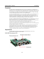
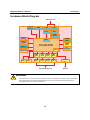
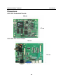
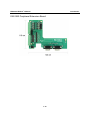
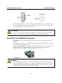
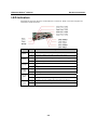
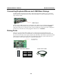
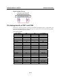
EM-2260 Hardware Development Kit User’s Manual First Edition, December 2008 www.moxa.com/product © 2008 Moxa Inc. All rights reserved. Reproduction without permission is prohibited. EM-2260 Hardware Development Kit User’s Manual The software described in this manual is furnished under a license agreement and may be used only in accordance with the terms of that agreement. Copyright Notice Copyright © 2008 Moxa Inc. All rights reserved. Reproduction without permission is prohibited. Trademarks MOXA is a registered trademark of Moxa Inc. All other trademarks or registered marks in this manual belong to their respective manufacturers. Disclaimer Information in this document is subject to change without notice and does not represent a commitment on the part of Moxa. Moxa provides this document “as is,” without warranty of any kind, either expressed or implied, including, but not limited to, its particular purpose. Moxa reserves the right to make improvements and/or changes to this manual, or to the products and/or the programs described in this manual, at any time. Information provided in this manual is intended to be accurate and reliable. However, Moxa assumes no responsibility for its use, or for any infringements on the rights of third parties that may result from its use. This product might include unintentional technical or typographical errors. Changes are periodically made to the information herein to correct such errors, and these changes are incorporated into new editions of the publication. Technical Support Contact Information www.moxa.com/support Moxa Americas: Toll-free: 1-888-669-2872 Tel: +1-714-528-6777 Fax: +1-714-528-6778 Moxa China (Shanghai office): Toll-free: 800-820-5036 Tel: +86-21-5258-9955 Fax: +86-10-6872-3958 Moxa Europe: Tel: +49-89-3 70 03 99-0 Fax: +49-89-3 70 03 99-99 Moxa Asia-Pacific: Tel: +886-2-8919-1230 Fax: +886-2-8919-1231 Table of Contents Chapter 1 Introduction ..................................................................................................1-1 Overview.................................................................................................................................. 1-2 Appearance .............................................................................................................................. 1-2 EM-2260 Development Kit ........................................................................................ 1-2 EM-2260 Embedded Module ..................................................................................... 1-3 EM-2260-DK Carrier Board and Peripheral Extension Board ................................... 1-3 Package Checklist .................................................................................................................... 1-4 Features.................................................................................................................................... 1-4 Hardware Block Diagram ........................................................................................................ 1-5 Hardware Specifications .......................................................................................................... 1-6 Hive-Based Registry—Contrast to RAM-Based Registry ....................................................... 1-8 Dimensions .............................................................................................................................. 1-9 EM-2260 Embedded Module ..................................................................................... 1-9 EM-2260-DK Carrier Board....................................................................................... 1-9 EM-2260 Peripheral Extension Board...................................................................... 1-10 Chapter 2 Hardware Installation...................................................................................2-1 Wiring Requirements ............................................................................................................... 2-2 Connecting the Power .............................................................................................................. 2-2 Resetting Your EM-2260 Computer......................................................................................... 2-3 LED Indicators......................................................................................................................... 2-4 Connecting to a Display........................................................................................................... 2-5 Connecting Keyboard/Mouse and USB Mass Storage............................................................. 2-6 Debug Ports ............................................................................................................................. 2-6 Serial Ports............................................................................................................................... 2-7 Insert CompactFlash Card........................................................................................................ 2-7 LAN Ports................................................................................................................................ 2-8 Real Time Clock ...................................................................................................................... 2-9 Connecting to the DI/DO ......................................................................................................... 2-9 Pin Assignments of CN1 and CN2......................................................................................... 2-10 Appendix A Regulatory Approval Statement ................................................................ A-1 1 Chapter 1 Introduction Thank you for purchasing the Moxa EM-2260 RISC-based industrial ready-to-run embedded module. This manual introduces the hardware installation, connector interfaces as well as software configurations of the EM-2260 Embedded Module and EM-2260 Development Kit. The following topics are covered in this chapter: Overview Appearance ¾ EM-2260 Development Kit ¾ EM-2260 Embedded Module ¾ EM-2260-DK Carrier Board and Peripheral Extension Board Package Checklist Features Hardware Block Diagram Hardware Specifications Hive-Based Registry—Contrast to RAM-Based Registry Dimensions ¾ EM-2260 Embedded ModuleEM-2260-DK Carrier Board ¾ EM-2260 Peripheral Extension Board EM-2260 HW User’s Manual Introduction Overview The Moxa EM-2260 Embedded Module features Cirrus Logic ARM9 CPU, 128 MB RAM, 32 MB Flash Disk, dual 10/100 Mbps Ethernet, eight digital inputs and eight digital outputs, four high speed serial ports, two USB 2.0 Hosts and an EIDE interface for external storage connection such as CompactFlash card. In addition, with built-in VGA interface, EM-2260 is suitable for SCADA system in industrial applications, that require VGA and HMI features. The EM-2260 Embedded Module uses Cirrus Logic EP9315 ARM9, 32-bit, 200 MHz RISC CPU. This powerful computing engine supports several useful communication functions, without generating a lot of heat. This module has a compact design that is easily integrated with a variety of industrial applications, including gas stations, vending machines, and ticketing machines, and offers a powerful serial communication capability for better system integration. The built-in 32 MB NOR Flash ROM and 128 MB SDRAM give you enough memory to run your application software directly on the EM-2260. Programmers will find the pre-installed, ready-to-run Windows CE 6.0 or Linux platform and full-function development kit a great benefit for developing software and building reliable communication applications. In addition to the standard model, the EM-2260 Embedded Module also comes in wide temperature model that offers the operating temperature range from -40 to 75°C, and is appropriate for harsh industrial automation environments. The EM-2260 Development Kit, which is designed for system and software development at the system evaluation stage, is also available. The kit combines the EM-2260 and carrier board EM-2260-DK. It is convenient for users to evaluate the functionality of EM-2260, develop and integrate the specific systems on it in advance, enabling EM-2260 embedded module to be completely compatible with the industrial systems and applications. Appearance The EM-2260 Development Kit contains EM-2260 embedded module, carrier board (EM-2260-DK) and Peripheral Extension Board. EM-2260 Development Kit 1-2 EM-2260 HW User’s Manual Introduction ATTENTION The EM-2260 package includes the EM-2260 embedded module only. The EM-2260 Development Kit is available for evaluation purposes. EM-2260 Embedded Module Front View Rear View EM-2260-DK Carrier Board and Peripheral Extension Board EM-2260-DK Peripheral Extension Board 1-3 EM-2260 HW User’s Manual Introduction Package Checklist The EM-2260 Development Kit contains the following items: y EM-2260 Embedded Module y EM-2260-DK, the carrier board of the EM-2260 Development Kit y Peripheral Extension Board y Quick Installation Guide y Document & Software CD y Cross-over Ethernet cable y Universal Power Adapter y Product Warranty Paper ATTENTION Notify your sales representative if any of the above items are missing or damaged. Features The EM-2260 Embedded Module/EM-2260 Development Kit has the following features: y Cirrus Logic EP9315 ARM9 CPU, 200 MHz y 128 MB RAM on-board, 32 MB Flash Disk y Graphical interface for external VGA output connection y 4 high speed TTL serial ports y Dual 10/100 Mbps Ethernet for network redundancy y 8+8 DI/DO y Support EIDE interface and USB 2.0 Host y Ready-to-Run WinCE 6.0 or Linux platform y Full-function development kit for quick evaluation and application development 1-4 EM-2260 HW User’s Manual Introduction Hardware Block Diagram Ethernet x 2 USB 2.0 Host x 2 VGA LAN LAN PHY PHY LAN Controller Power Circuit 128MB RAM MAC Power Circuit RTC UART Watchdog DIx8 32MB Flash Cirrus Logic EP9315 32-bit ARM9 200 MHz DOx8 MOXA UART ASIC MOXA UART ASIC MOXA UART ASIC MOXA UART ASIC Serial Port 1 Serial Port 2 Serial Port 3 Serial Port 4 RS-232/422/485 x 4 CF Function Console Port RS-232 ATTENTION The dual Power Circuit, extra LAN controller and CF card socket are support only by EM-2260 Development Kit. EM-2260 embedded module connects to all the input/output peripherals through signals of two 100-pin connectors. 1-5 EM-2260 HW User’s Manual Introduction Hardware Specifications EM-2260 embedded module supports all the peripherals through signals of two 100-pin connectors, CN1 and CN2. Differences of EM-2260 embedded module and EM-2260 Development Kit will be specially specified. System CPU: Cirrus Logic EP9315 ARM9 CPU, 200 MHz DRAM: 128 MB onboard (optional 256 MB) Flash: 32 MB Flash onboard Storage Expansion: EM-2260: EIDE Interface signals support up to 2 external devices connection EM-2260 Development Kit: CompactFlash socket x 1 for storage expansion USB: EM-2260: Signals support USB 2.0 Host (OHCI) x3 EM-2260 Development Kit: USB 2.0 Host (OHCI) x 2, Type A connector Console/Debugging Port: RS-232 x 1 (TxD, RxD, GND), 4-pin header output LED EM-2260 Development Kit: System: Power x 1, Ready x 1, Storage x 1 LAN: 10M/Link x 2 (on connector), 100M/Link x 2 (on connector) Serial: TxD x 4, RxD x 4 Others: RTC, buzzer, Watchdog Timer, Reset button Display Graphical Controller: EP9315 internal graphics accelerator engine with TTL graphical signal support Display Memory: Dynamic video memory, share system memory Graphical Resolution: 1024 x 768, 18-bit Serial Communication Serial Port EM-2260: Signals support High speed TTL serial port x 4 (TxD, RxD, DTR, DSR, RTS, CTS, DCD, GND) EM-2260 Development Kit: RS-232/422/485 D-Sub male 9-pin connector x 4, software-selectable. RS-232 signals: TxD, RxD, DTR, DSR, RTS, CTS, DCD, GND RS-422 signals: TxD+, TxD-, RxD+, RxD-, GND 4-wire RS-485 signals: TxD+, TxD-, RxD+, RxD-, GND 2 -wire RS-485 signals: Data+, Data-, GND 1-6 EM-2260 HW User’s Manual Introduction Protection EM-2260 Development Kit: Built-in 15KV ESD protection for all signals, 2KV optical isolation protection Data bits: 5, 6, 7, 8 Stop bits: 1, 1.5, 2 Parity: None, Even, Odd, Space, Mark Flow Control: RTS/CTS, XON/XOFF, RS-485 ADDCTM Speed: 50 bps to 921.6 Kbps, support ANY BAUD RATE Network Communication LAN: Auto-sensing 10/100Mbps x 2, RJ45 Protection: Build-in 1.5KV magnetic isolation protection Digital Input Input Channels EM-2260: Signals of 8 input channels EM-2260 Development Kit: 8, source type Digital Input Levels EM-2260: 3.3V, CMOS level EM-2260 Development Kit: Dry contact: Open. Logic level 0 -- Close to GND, Logic level 1 – Wet contact: Logic level 0 -- +3V max, Logic level 1: +10V ~ +30V (COM to DI) Protection EM-2260 Development Kit: 3KV optical isolation protection Connector Type EM-2260 Development Kit: 10 Pin Screw Terminal Block (8 points / COM / GND) Digital Output Input Channels EM-2260: Signals of 8 output channels EM-2260 Development Kit: 8, sink type Digital Output Levels EM-2260: 3.3V, CMOS level EM-2260 Development Kit: On-state Voltage -- 24V DC nominal, open collector to 30 V Output Current Rating -- Max. 200mA per channel Protection EM-2260 Development Kit: 3KV optical isolation protection 1-7 EM-2260 HW User’s Manual Introduction Connector Type EM-2260 Development Kit: 9-pin Screw Terminal Block Power Requirments Power Input EM-2260: +5V DC and +3.3V DC EM-2260 Development Kit: Dual power input design PWR1: 12 to 48V DC, power jack with thread PWR2: 12 to 48V DC, 3-pin terminal block Power Consumption EM-2260: 5.4 W EM-2260 Development Kit: 783 mA @ 12V DC without loading of USB ports 1.2A @ 12V DC with loading of USB ports Mechanical Dimensions EM-2260: 87 x 106 mm EM-2260 Development Kit: Environmental 110 x 146 mm Operating Temperature: -10 to 60°C (14 to 140°F) Storage Temperature: -20 to 80°C (-4 to 176°F), 5 to 95% RH Regulatory Approvals and Warranty EMC: FCC, CE (Class A) Others: RoHS, WEEE Warranty: 5 years Hive-Based Registry—Contrast to RAM-Based Registry The registry for the EM-2260 is a hive-based registry in contrast to a RAM-based registry. The hive-based registry stores registry data inside files, or hives, which can be kept on any file system. This removes the need for performing backup and restore on power off. 1-8 EM-2260 HW User’s Manual Introduction Dimensions EM-2260 Embedded Module EM-2260-DK Carrier Board 1-9 EM-2260 HW User’s Manual Introduction EM-2260 Peripheral Extension Board 1-10 2 Chapter 2 Hardware Installation The EM-2260 Embedded Module is designed to be integrated directly into the user’s system and application. The pre-installed Windows CE 6.0 or Linux makes it easy for users to develop programs for a variety of applications. The EM-2260 Development Kit is a well-designed embedded computer with complete peripheral interfaces. This kit helps users to evaluate, develop, and integrate the EM-2260 Embedded Module into their systems and applications. Simply combine the EM-2260 Embedded Module with the Development Kit to start porting the relevant software, and create a solution for the applications you wish to implement. The following topics are covered in this chapter: Wiring Requirements Connecting the Power Resetting Your EM-2260 Computer LED Indicators Connecting to a Display Connecting Keyboard/Mouse and USB Mass Storage Debug Ports Serial Ports Insert CompactFlash Card LAN Ports Real Time Clock Connecting to the DI/DO Pin Assignments of CN1 and CN2 EM-2260 HW User’s Manual Hardware Installation Wiring Requirements Please follow the following common safety precautions before proceeding with the installation of any electronic device: y Use separate paths to route wiring for power and devices. If power wiring and device wiring paths must cross, make sure the wires are perpendicular at the intersection point. y You can use the type of signal transmitted through a wire to determine which wires should be kept separate. The rule of thumb is that wiring that shares similar electrical characteristics can be bundled together. y Keep input wiring and output wiring separate. y When necessary, it is strongly advised that you label wiring to all devices in the system. ATTENTION Do not run signal or communication wiring and power wiring in the same wire conduit. To avoid interference, wires with different signal characteristics should be routed separately. ATTENTION Safety First! Be sure to disconnect the power cord before installing and/or wiring. Electrical Current Caution! Calculate the maximum possible current in each power wire and common wire. Observe all electrical codes dictating the maximum current allowable for each wire size. If the current goes above the maximum ratings, the wiring could overheat, causing serious damage to your equipment. Temperature Caution! Be careful when handling the unit. When the unit is plugged in, the internal components generate heat, and consequently the outer casing may feel hot to the touch. Connecting the Power EM-2260 Development Kit provides 2 kinds of power input, power jack and 3-pin terminal block, both of them allow 12 to 48V DC power input, and are able to work at the same time, providing redundant power solution. If the power is properly supplied, the Power LED will light up first, and then, it takes about 30 to 60 seconds for the operating system to boot up. Once the system is ready, the Ready LED will light up. 2-2 EM-2260 HW User’s Manual Hardware Installation SG The Shielded Ground (SG, sometimes called Protected Ground) helps to limit the effects of noise due to electromagnetic interference (EMI). Run the ground connection from the ground screw to the grounding surface prior to connecting devices. ATTENTION The power for this product is intended to be supplied by a Listed Power Supply Unit, and rated to deliver 12 to 48V DC at a minimum of 1200mA for 12V DC, 260mA for 48V DC. Resetting Your EM-2260 Computer Cold-Start: Disconnect power and then connect the power again. The computer reboots itself right away. Warm-Start: In power-on state, push the Reset Switch near power terminal block and release it in 1 second. The computer reboots itself. Reset to Factory Default: If the computer is not working properly, and you want to load factory default settings. Press the Reset Switch for at least 5 seconds. After the factory default configuration has been loaded, the system will reboot automatically. WARNING Reset to Default preserves user’s data. It will NOT format the user directory and erase the user’s data, pressing the Reset to Default will only load the configuration file. If the computer cannot start up, please use Console Port and go to the Boot Loader to format the file system. After the formatting procedure is done, you should be able to restart it. 2-3 EM-2260 HW User’s Manual Hardware Installation LED Indicators EM-2260 Development Kit has 15 LED indicators on the front. Refer to the following table for information about each LED. LED Power Color Green Off Ready Green Off Storage Green Off Description Power is ON. No power is being received, or power error exists. OS is ready and functioning normally (after booting up). OS is not ready. Data is being written to or read from the storage unit. Storage unit is idle. LAN1, LAN2 Orange 10 Mbps Ethernet connection Green 100 Mbps Ethernet connection P1-P4 (TX) Green Serial port is transmitting TX data to the serial device. P1-P4 (RX) Orange Serial port is receiving RX data from the serial device. Off Off Serial port is not transmitting TX data to the serial device. Serial port is not receiving RX data to the serial device. 2-4 EM-2260 HW User’s Manual Hardware Installation Connecting to a Display EM-2260 Development Kit comes with a D-Sub 15-pin female connector to connect to VGA monitor. Be sure to remove power before you connect or disconnect the monitor cable. DB15 Female Connector Pin No. Signal Definition 1 Red 2 Green 3 Blue 4 --- 5 GND 6 GND 7 GND 8 GND 9 --- 10 GND 11 --- 12 --- 13 H-Sync 14 V-Sync 15 --- 2-5 EM-2260 HW User’s Manual Hardware Installation Connecting Keyboard/Mouse and USB Mass Storage The EM-2260 Development Kit provides 2 USB 2.0 full speed hosts (OHCI), type A connector, which support not only keyboard or mouse, but also the ability to connect a flash disk for storing large amounts of data. When an empty USB storage device is plugged into the USB ports of the EM-2260 Development Kit, the computer automatically formats it to the FAT system. A directory named “USBDisk” under the root directory is created as a link to the first USB mass storage device that is plugged-in. The directory created for the second plugged-in USB device is “USBDisk2”. Debug Ports There is a 4-pin pin-header RS-232 debug port (or called console port) designed for serial terminals, which gives users a convenient way of connecting the development workstation (The PC) to the console utility of the target computer (The EM-2260). This method is particularly useful when using the computer for the first time or for debugging while the system cannot boot up. A special Serial Console Cable (Optional) is needed for this function. Serial Console Port & Pinouts 4 3 2 1 Pin 1 2 3 4 Serial Console Cable Signal TxD RxD NC GND 2-6 EM-2260 HW User’s Manual Hardware Installation Serial Ports EM-2260 Development Kit offers 4 software-selectable serial ports. Each port can be configured by software for RS-232, RS-422, or RS-485. The pin assignments for the ports are shown in the following table: 1 2 3 4 5 6 7 8 9 Pin 1 2 3 4 5 6 7 8 RS-232 DCD RxD TxD DTR GND DSR RTS CTS RS-422 TxDA(-) TxDB(+) RxDB(+) RxDA(-) GND ------- RS-485 (4-wire) TxDA(-) TxDB(+) RxDB(+) RxDA(-) GND ------- RS-485 (2-wire) ----DataB(+) DataA(-) GND ------- Insert CompactFlash Card EM-2260 Development Kit comes with a CompactFlash socket. A mass storage card is considered to be a standard attachment to the computer. Thus, when an empty mass storage card is inserted into the slot, the computer automatically formats it to the FAT system. This process takes a few minutes to complete. The EM-2260, when a mass storage card is inserted, creates a directory named “HardDisk” under the root directory and the newly created directory serves a link to the storage. There are some CompactFlash storage disks which are not compatible with EM-2260. You could try the other CompactFlash storage or disable ultra DMA by using the “System Manager” to change this setting. 2-7 EM-2260 HW User’s Manual Hardware Installation The following table describes the compatible CompactFlash storages list that we had tested successfully. Vendor ScanDisk Transcend Apacer Unigen Device Name Ultra II Compact Flash 80X Photo CIENO Compact Flash card Size 1GB 512MB 2GB 128MB ATTENTION The EM-2260 does not support CompactFlash hot swap and PnP (Plug and Play) function. It is necessary to remove power source first before inserting or removing the CompactFlash card. LAN Ports EM-2260 Development Kit Embedded Module offers 2 LAN ports supporting 10/100 Mbps. The default IP addresses and netmasks of the network interfaces are as follows: 8-pin RJ 45 10 Mbps indicator 8 Pinouts Pin 1 2 3 4 5 6 7 8 100 Mbps indicator 1 Default IP Address Netmask LAN 1 192.168.3.127 255.255.255.0 LAN 2 192.168.4.127 255.255.255.0 2-8 Signal ETx+ ETxERx+ ----ERx----- EM-2260 HW User’s Manual Hardware Installation Real Time Clock The EM-2260’s real time clock is powered by a lithium battery. We strongly recommend that you do not replace the lithium battery without help from a qualified Moxa support engineer. If you need to change the battery, contact the Moxa RMA service team. WARNING There is a risk of explosion if the battery is replaced by an incorrect type Connecting to the DI/DO The EM-2260 Development Kit has 8 digital inputs and 8 digital outputs, both of them support 3KV optical isolation protection. The pinouts for the I/O are shown below. Digital Input Wiring Dry Contact Wet Contact WARNING If you are using wet contacts, you must supply power to “COM”. 2-9 EM-2260 HW User’s Manual Hardware Installation Digital Output Wiring Pin Assignments of CN1 and CN2 There are two 100-pin connectors on the rear of EM-2260 embedded module, to independently use EM-2260 Embedded Module for developing your own system, please refer to the following tables for the pin assignments of CN1 and CN2. CN1 Pin Assignment CN1 Signals NC EGPIO9 UR1_232EN UR1_TENA UR1_TENB UR1_REN UR1_RTS UR1_DTR UR1_TXD UR1_RXD UR1_CTS UR1_DCD UR1_DSR UR2_232EN UR2_TENA UR2_TENB UR2_REN UR2_RTS UR2_DTR UR2_TXD UR2_RXD UR2_CTS UR2_DCD UR2_DSR UR3_232EN Pin 2 4 6 8 10 12 14 16 18 20 22 24 26 28 30 32 34 36 38 40 42 44 46 48 50 Pin 1 3 5 7 9 11 13 15 17 19 21 23 25 27 29 31 33 35 37 39 41 43 45 47 49 2-10 CN1 Signals XP XM YP YM SXP SXM SYP SYM GND USB_P0 USB_M0 GND USB_P1 USB_M1 GND USB_P2 USB_M2 GND CPU_TXD0 CPU_RXD0 CPU_CTS# CPU_RTS# CPU_DTR# CPU_DSR# ARST# EM-2260 HW User’s Manual Hardware Installation CN1 Pin Assignment (Continue) CN1 Signals UR3_TENA UR3_TENB UR3_REN UR3_RTS UR3_DTR UR3_TXD UR3_RXD UR3_CTS UR3_DCD UR3_DSR UR4_232EN UR4_TENA UR4_TENB UR4_REN UR4_RTS UR4_DTR UR4_TXD UR4_RXD UR4_CTS UR4_DCD UR4_DSR +5V +5V +5V +5V Pin 52 54 56 58 60 62 64 66 68 70 72 74 76 78 80 82 84 86 88 90 92 94 96 98 100 Pin 51 53 55 57 59 61 63 65 67 69 71 73 75 77 79 81 83 85 87 89 91 93 95 97 99 CN1 Signals ABITCLK ASYNC ASDI ASDO GND TX1+ TX1GND RX1+ RX1GND TX2+ TX2GND RX2+ RX2GND CAN_TX0 GND CAN_TX1 GND CAN_RX0 GND CAN_RX1 +5V Pin 2 4 6 8 10 12 14 16 18 20 22 24 26 28 30 32 34 36 38 40 Pin 1 3 5 7 9 11 13 15 17 19 21 23 25 27 29 31 33 35 37 39 CN2 Signals DD0 DD1 DD2 DD3 DD4 DD5 DD6 DD7 DD8 DD9 DD10 DD11 DD12 DD13 DD14 DD15 IDE_CS#1 IDE_CS#3 IDE_A0 IDE_A1 CN2 Pin Assignment CN2 Signals DIN0 DIN1 DIN2 DIN3 DIN4 DIN5 DIN6 DIN7 DOUT0 DOUT1 DOUT2 DOUT3 DOUT4 DOUT5 DOUT6 DOUT7 BRIGHT LCD_P0 LCD_P1 LCD_P2 2-11 EM-2260 HW User’s Manual LCD_P3 LCD_P4 LCD_P5 LCD_P6 LCD_P7 Hardware Installation 42 44 46 48 50 41 43 45 47 49 IDE_A2 INT3_CF IDE_DREQ IORDY DMACK# Pin 51 53 55 57 59 61 63 65 67 69 71 73 75 77 79 81 83 85 87 89 91 93 95 97 99 CN2 Signals DIOW# DIOR# GND ROW0 ROW1 ROW2 ROW3 ROW4 ROW5 ROW6 ROW7 COL0 COL1 COL2 COL3 COL4 COL5 COL6 COL7 +3.3V +3.3V +3.3V +3.3V +3.3V +3.3V CN2 Pin Assignment (Continue) CN2 Signals LCD_P8 LCD_P9 LCD_P10 LCD_P11 LCD_P12 LCD_P13 LCD_P14 LCD_P15 LCD_P16 LCD_P17 SPCLK BLANK HSYNC VSYNC P1_10_ACT P1_100_ACT P2_LINK P2_100_ACT SW_RELOAD RESET#-1 P1_LINK SW_READY +3.3V +3.3V +3.3V Pin 52 54 56 58 60 62 64 66 68 70 72 74 76 78 80 82 84 86 88 90 92 94 96 98 100 2-12 A Appendix A Regulatory Approval Statement This device complies with part 15 of the FCC Rules. Operation is subject to the following two conditions: (1) This device may not cause harmful interference, and (2) this device must accept any interference received, including interference that may cause undesired operation. Class A: FCC Warning! This equipment has been tested and found to comply with the limits for a Class A digital device, pursuant to part 15 of the FCC Rules. These limits are designed to provide reasonable protection against harmful interference when the equipment is operated in a commercial environment. This equipment generates, uses, and can radiate radio frequency energy and, if not installed and used in accordance with the instruction manual, may cause harmful interference to radio communications. Operation of this equipment in a residential area is likely to cause harmful interference in which case the user will be required to correct the interference at his own expense. European Community Warning: This is a class A product. In a domestic environment this product may cause radio interference in which case the user may be required to take adequate measures.


![Model DO402G Dissolved Oxygen Converter [Style: S3]](http://vs1.manualzilla.com/store/data/005725233_1-bd7e4c5bf258da59a958f30153ff00ea-150x150.png)