1
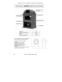
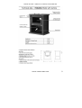
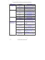
ESTUFAS ROFER – MANUAL DE INSTALACIÓN Y USO
CHIMENEAS ROFER & RODI
1
ROFER STOVES – MANUAL OF INSTALLATION AND USE
Contents:
Warning for the installer and user:
CE Brand
1.- GENERAL DESCRIPTION
2.- INSTALLATION INSTRUCTIONS
2.1.- Assembly of the stove
2.2.- Site of installation
2.3.- Assembly of the smoke ducts
3.- INSTRUCTIONS FOR USE
3.1.- Fuel and Lighting
3.2.- Cleaning and Maintenance
4. TECHNICAL DATA
4.1.- General Characteristics
4.2.- Technical Catalogue
4.3.- Spare Parts
4.4.- Probable causes of failure or irregular functioning
4.5.- CE Declaration of compliance
IMPORTANT: WARNING FOR THE INSTALLER AND USER:
• The proper functioning of the stove will depend on its correct installation and use.
To achieve this it is essential to read carefully and follow the general instructions
and those relating to each model set out in the section on technical data.
• The installation of the fireplace and of the smoke duct should be carried out in
observance of all the local regulations, including those referring to national and
European norms.
• An incorrectly installed fireplace or one with a defective chimney installation could
cause damage to the apparatus and set on fire the soot accumulated in the
chimney draught causing a risk of fire, back-puffing smoke, etc...
• The manufacturer refuses any responsibility for damage or deterioration caused
by the use of fuels not recommended or by unauthorised alterations made to the
device or the installation. The installation and repair of the device as well as the
periodic maintenance of the chimney draught must be carried out by qualified
professionals. Failure to observe the instructions for installation and use will result
in the invalidation of the manufacturer’s warranty.
• The installation and repair of the device as well as the periodic maintenance of
your fireplace should be carried out by qualified technicians. Should any queries
arise regarding these matters please contact the nearest supplier of Rofer & Rodi
Fireplaces.
ROFER & RODI FIREPLACES
19
ROFER STOVES – MANUAL OF INSTALLATION AND USE
08
UNE-EN 13240
Manufacturer:
Rofer Axarquía S.L.
Family / Models
ROFER stoves.
Heating power
Models Hispalis, Tarsis, Iliberis,
Italica, Malaka, Abdera
11.5 kW
Energetic Performance
Minimum distance to adjacent
fuel materials
Carbon Monoxide emission at
13% of Oxygen
Temperature of smoke emissions
61%
1.2 m
0.6%
400° C
Stove using natural firewood as fuel,
for intermittent use and functioning with closed doorRead and follow the instructions for installation and use.
Use only the recommended fuels.
20
ROFER & RODI FIREPLACES
ROFER STOVES – MANUAL OF INSTALLATION AND USE
1.- GENERAL DESCRIPTION
• The models of ROFER stoves offer greater performance and safety thanks to
their careful design and the use of the highest quality components. The device
conforms to regulations UNE EN-13240.
• These models are fitted with a vitro ceramic glass door, a floor with grille and an
ashes box that can be dismantled to enable cleaning. The best performance is
obtained from the models fitted with heating chamber and turbine.
• To complete the range of stoves we have models containing oven, decorative
hood, skirting... which can be adapted to any style of decoration.
ROFER & RODI FIREPLACES
21
ROFER STOVES – MANUAL OF INSTALLATION AND USE
2.- INSTALLATION INSTRUCTIONS
2.1.- Assembly of the stove
• The stove, ducts and hood should not be installed next to coatings, wood parquet
or other potentially inflammable elements which should be kept at a safety
distance of 1.2 m from the device. A safety distance of 0.5m should be maintained
where the smoke ducts pass next to electrical conduits or other installations fitted
into the brickwork.
• To guarantee the correct insulation of the device and the fireplace outlets, fire
bricks, ceramic and steel plates etc. should be used.
• The stove is designed for free standing installation, although it can be inserted
into a heat resistant chamber providing an air chamber of at least 10 cm is kept
around the stove. In such a case access must be ensured to the rear draught
regulator and the upper cover opening should the stove model have one.
2.2.- Site of installation
• Owing to the risk of fire, the installation is not authorised in houses with wooden
frames, beams or roof, or asphalt roofing felt...unless these are built according to
technical plans that guarantee the proper insulation of the device, smoke outlets
and fireplace coping hood.
• The floor surface on which the installation is placed should be able to support the
load or total weight of the stove, pipes, etc. In the event of this condition not be
observed, the forging work can be reinforced by means of a metal structure or the
load can be distributed by the laying of a reinforced concrete slab. Consult a
qualified technician before carrying out any of these measures.
• The site of the stove installation should have sufficient ventilation to provide a
natural draught and allow for air recycling. If the dwelling is fitted with mechanical
air conditioning units or extractors, when these begin to function the air intake for
the fireplace draught is likely to be insufficient and it will be necessary to install an
exterior air inlet grille which must not be sealable, as close as possible to the
stove, with a minimum section size of 100 cm2. As a general rule, we recommend
the installation of this type of grille as it ensures that your fireplace will have an
adequate combustion and draught.
22
ROFER & RODI FIREPLACES
ROFER STOVES – MANUAL OF INSTALLATION AND USE
2.3.- Assembly of the smoke ducts
• A metallic pipe of a specified diameter must be used for the evacuation of
smoke through the whole length of the chimney draught. In accordance with
current regulations, we recommend the use of a stainless or vitrified steel pipe. In
the event of an exterior assembly, this should be of a modular double panel type.
• Avoid reducing the diameter of the pipe, the use elbow bends of more than
45º and the connection of various devices to the same duct, as this could
cause the back-puffing of smoke.
• In the event of requiring insulation in a section of the chimney draught, we
recommend the use of ceramic heat resistant panels.
• The draught should have a minimum height of 4m, and rise to at least 50cm
above the highest section of the roof. It should be placed at a distance of over 8m
from any adjacent building. For the coping of the chimney it is advisable to
use standardised prefabricated or metallic hoods.
• When joining together the pipes the nozzle end should be pointing upwards. To
ensure a faultless sealing between the stove and the wrought ironwork, heat
resistant putty may be used.
ROFER & RODI FIREPLACES
23
ROFER STOVES – MANUAL OF INSTALLATION AND USE
• The smoke duct and the hood of each device should be individual. Do not connect
2 or more heating devices to the same smoke duct.
• In order to prevent the soot accumulated in the chimney draught catching fire, with
its consequent fire hazard, the draught should be cleaned at periodic intervals
using mechanical means carried out by qualified technical staff.
• Where necessary, fit dampers to ensure that the installation of the smoke ducts
and the coping hood do not obstruct the mechanical removal of soot from the
chimney draught.
3.- INSTRUCTIONS FOR USE
IMPORTANT
• Contact with the lighted stove or with the vitro ceramic glass can cause
burns. For reasons of safety, do not allow children to go near the lighted stove,
moreover once the stove has been extinguished, take the necessary
precautionary measures as the device will remain hot for a certain period of
time afterwards.
• A safety distance of 1.2 m around the device should be observed inside
which no potentially inflammable materials should be placed. Take into account
that even though there may be no direct contact, there may exist a risk of damage
and even fire due to the heat radiation. For this reason do not place inside the
indicated area wood or plastic furnishings, wallpaper, fitted carpeting, carpet rugs,
curtains, etc...
3.1.- Fuel and Lighting
• This device is not an incinerator. Do not use it to burn domestic waste, cardboard,
magazines, etc.
• You are advised to use dry firewood of low resin content (for example, beech,
oak, chestnut, elm, olive or holm-oak). The recommended maximum size of
firewood is 30 cm long and 15 cm diameter. Do not use chipboard or wood with
paint or varnish remains. Under no circumstances should liquid fuel or coal
briquettes be used to light the stove.
• As a help in the lighting of the fire a mixture of fine and bulky firewood can be
used. Once it is functioning, the door must remain closed, except when being
opened for refuelling, in which case do so slowly to avoid the back-puffing of
smoke. Observe the maximum load indicated.
24
ROFER & RODI FIREPLACES
ROFER STOVES – MANUAL OF INSTALLATION AND USE
• During the first lighting some smoke may appear as a result of the drying of the
protective coat of heat-resistant paint applied to the stove. For this reason we
recommend that you ventilate the premises until this smoke disappears.
Draught Adjustment (optional)
• To improve the performance, the ROFER stove models have an optional fitting of
an adjustable draught operated by a handle located on the rear section:
To open the draught: turn to vertical position
To close the draught: turn to horizontal position
• The lighting of the stove is helped by opening the adjustable grille on the ashes
box and opening the draught. When the fire has taken well, the grille can be
closed and regulate the draught in order to reduce fuel consumption. The draught
must never be closed when the door is open.
• Contact with the lighted stove or with the vitro ceramic glass can cause
burns. For this reason, in order to adjust the draught and open the door you
should use the handle supplied with the device.
Regulation of air for heating (only in models fitted with turbines)
• In order to control the flow of hot air, the stove is fitted with a three-position
switch:
Position 0: Automatic mode – minimum speed
Position I: Manual Mode – minimum speed
Position II: Manual Mode – maximum speed
• At Position 0, by means of a thermostat, the turbines start functioning
automatically once a pre-set temperature has been reached (normally 15-20
minutes after lighting); the same turbines switch off when the stove temperature
falls.
• To get full benefit from the heating power of the stove we recommend using
Position II. Once the desired room temperature has been reached you can switch
to Position I. If you want the turbines to switch off automatically after the fire
has been put out, switch to Position 0.
ROFER & RODI FIREPLACES
25
ROFER STOVES – MANUAL OF INSTALLATION AND USE
Diagram and Connection to the electricity mains (only in models
fitted with turbines)
• During the normal use of the device and whilst it is lighted, you are advised not to
disconnect it from the electrical mains. However, a permanent connection must
not be made in the fuse box but preferably by means of an approved model of
plug with an earth wire which, when required, allows the user to disconnect it.
• Remember that your stove is connected to the electrical mains. It must not be
extinguished with water as, in addition to causing a safety hazard, it could
damage the device and its electrical components.
3.2.- Cleaning and Maintenance
• For the cleaning of the exterior a dry cloth should be used, and should not
be moistened or used with any abrasive product that may damage the
paintwork.
• The glass should be cleaned when cold, using a product specially designed for
fireplaces, or any brand of oven cleaner. In the event of persistent stains, a glass
scraper can be used. Remember that the vitro ceramic glass is resistant to
temperature but being fragile any impact may cause it to break.
• The cleaning out of the ashes is done by removing the interior fireplace grille and
collecting up the ashes in the box, making sure beforehand that the live embers
are fully extinguished.
• In order to prevent the soot accumulated in the chimney draught catching fire, with
its consequent fire hazard, the draught should be cleaned at periodic intervals
using mechanical means carried out by qualified technical staff at least once a
year.
• In the event of this soot catching fire close the draught and call the fire service
immediately.
26
ROFER & RODI FIREPLACES
ROFER STOVES – MANUAL OF INSTALLATION AND USE
4. TECHNICAL DATA
4.1.- General Characteristics
• The ROFER stove is a device that complies with obligatory regulations UNE
EN-13240.
Normal heat output:
11.5 Kw
Performance:
61%
CO concentration at 13% oxygen
0.6%
Smoke flow
15 g/s
Optimum draught suction:
12.8 Pa
Average smoke temperature:
Minimum distance to adjacent
combustible materials
Combustion chamber:
400°C
Type of combustion:
Intermittent
Dry firewood from
natural wood
Length 30 cm
Diameter 15 cm
Fuel:
Maximum size of firewood:
1.2 M
Closed
The size, weight and other characteristics of each model are set out in the relevant
technical catalogue.
4.2.- Technical Catalogue
ROFER & RODI FIREPLACES
27
ROFER STOVES – MANUAL OF INSTALLATION AND USE
28
ROFER & RODI FIREPLACES
ROFER STOVES – MANUAL OF INSTALLATION AND USE
ROFER & RODI FIREPLACES
29
ROFER STOVES – MANUAL OF INSTALLATION AND USE
30
ROFER & RODI FIREPLACES
ROFER STOVES – MANUAL OF INSTALLATION AND USE
ROFER & RODI FIREPLACES
31
ROFER STOVES – MANUAL OF INSTALLATION AND USE
4.3.- Spare Parts
• To order spare parts indicate the serial number and year of manufacture figuring
on the plate attached to the device or on the warranty card. Only original spare
parts must be used.
Parts replaceable by the user:
Draught break plate. Firedog, Ashes grate, Ashes box, Grille knobs
Vitro ceramic glass: bear in mind that although resistant to temperature it is
fragile and any impact to it or to the fireplace may cause it to break. In
order to replace it the use of specialised tools may be required and
adequate protection measures need to be taken to avoid suffering cuts
during the handling of broken glass.
Parts replaceable only by qualified professional staff: (only in models
fitted with turbines).
Electrical cables, Turbines, Thermostat, Switch.
32
ROFER & RODI FIREPLACES
ROFER STOVES – MANUAL OF INSTALLATION AND USE
4.4.- Probable causes of failure or irregular functioning
• The device you have purchased is a high performance fireplace of
guaranteed quality. Nevertheless, certain extreme climate conditions such as
strong winds, hail storms or risks of freezing temperatures, may cause the
chimney draught to be inadequate. In view of the potential risk of back-puffing
smoke we advise you not to use the fireplace under such conditions as this will
not be considered as a defect or malfunction of the device.
• Owing to the high heating power of the fireplace, we do not recommend its
installation in small rooms as the resulting increase in temperature could cause a
heat shock hazardous to persons’ health. For this reason the device should not be
used during hot days or periods.
• Below is a detailed list of instructions on how to correct and avoid an irregular
functioning of the device and some example cases of failure with indications on
how to repair the problem.
IMPORTANT NOTE: the repair work or procedures indicated with an asterisk
(*) must be carried out by qualified professional staff.
The indications are valid only for models fitted with turbines.
Table 1
Description of failure
The turbines continue to
function after the device
has been turned off.
Probable cause
Switch is in position I/II
(manual connection)
Failure of thermostat
(*)
The turbines stop while
the device is in operation.
The switch is in
position 0 (automatic
connection)
No electrical supply
Turbine failure (*)
The protection circuit
differential of the dwelling
is activated when the
turbines start functioning.
The turbines function in
automatic mode but not in
manual mode.
Failure in the electrical
installation of the
dwelling or in the
device (*)
Malfunction of the
turbine switch (*)
Procedure
Turn the switch to position 0. This will
automatically disconnect the turbines
(after a time).
Disconnect the device from the
electricity mains and do not use again
until the device has been repaired.
As the temperature is falling
disconnection is automatically
activated. Press position I / II if you
wish to continue heating the room.
Check that the plug is correctly
inserted in the socket.
Disconnect the device from the
electricity mains and do not use again
until the device has been repaired.
Disconnect the device from the
electricity mains and do not use again
until the device has been repaired.
Disconnect the device from the
electricity mains and do not use again
until the device has been repaired.
ROFER & RODI FIREPLACES
33
ROFER STOVES – MANUAL OF INSTALLATION AND USE
Table 2
Irregular function
The device does not
generate sufficient
heat.
Probable cause
Course of action
The wood is of a poor
quality
Use only the types and sizes of firewood
recommended in the user’s manual.
There is an insufficient
amount of firewood
Load the device with the quantities
recommended in the user’s manual.
The premises may be too large for the
type of fireplace installed or they are
poorly insulated.
The premises are poorly
insulated
The fire does not light
sufficiently or goes out.
The firewood is damp
The firewood pieces are too
large
The chimney draught is
closed
The air inlet is closed
The fire is too high
The chimney draught is
open
The air inlet is open.
The firewood is of a poor
quality.
Smoke emanates
during the lighting
process or when the
device is functioning.
The smoke outlet duct is
cold
The chimney draught is
blocked
The draught is insufficient
Use of ventilators or
mechanical extractors
A defective installation of the
fireplace or use of
inadequate material
34
Use dry not damp or green firewood
To ensure the firewood sets alight it is
advisable to use small branches or twigs
that burn well. Use split firewood to stoke
up the hearth once lit.
Open the draught regulator and once the
firewood has caught fire sufficiently close
the draught again.
Open the lower air inlet and keep it open
for as long as is necessary.
Adjust the draught control and close
completely if necessary.
Close the lower air inlet.
Avoid using certain types of wood that
cause rapid burning such as chipboard,
ply wood, carpentry shop wood shavings
and sawdust, pine wood, etc.
The fire needs to be high as soon as it is
lit in order to heat up the duct. To achieve
this use fuel briquettes for barbeques and
fireplaces.
Check that there is no blockage in the
duct, particularly at hood level. Where
necessary clean out the soot
mechanically.
Check that the exterior air inlets are not
blocked. It may be necessary to lengthen
the smoke ducts in order to obtain the
optimal chimney draught suction.
In specific cases it may cause a suction
that prevents the device from functioning
correctly. In such event it will be
necessary to install an external air inlet
next to the fireplace.
A check on the ducts a hood should be
carried out by qualified professional staff.
ROFER & RODI FIREPLACES
ROFER STOVES – MANUAL OF INSTALLATION AND USE
CE Declaration of compliance
The manufacturer hereby Certifies that the fireplace models listed below
meet all the requirements of the EU Directive governing construction
products (89/106/EEC) and comply with regulations UNE-EN 13240:
2002 “Stoves using solid fuel-Testing requirements and methods”,
modified by UNE-EN 13240:2002 / A2:2005, UNE-EN 13240:2002 /
AC:2006, UNE-EN 13240:2002 / A2:2005 / AC:2006
Commercial brand: ROFER & RODI
Family / Models: ROFER stoves, models Híspalis, Tarsis, Ilíberis,
Itálica, Malaka, Abdera
Description:
Stove using natural firewood as fuel, for intermittent use and
functioning with closed door.
Heating power:
11.5 kW
Energy performance:
61%
Public Organism notified: Nº 1722 CEIS
Manufacturer: ROFER AXARQUIA, S.L.
Vega Melilla, plot 1 – P.O. Box 81
29740 – TORRE DEL MAR (Malaga) SPAIN
Signed: Andrés Román Cortés, Technical Director.
ROFER & RODI FIREPLACES
35
ROFER STOVES – MANUAL OF INSTALLATION AND USE
36
re FIREPLACES
ROFER & RODI


![installation & directions for use installation & mode d`emploi [ en ] [ fr ]](http://vs1.manualzilla.com/store/data/006516414_1-826c39eefa343060f035675bc430e123-150x150.png)